Embed Size (px)
Citation preview
Page 1
IST / DEEC / API
http://users.isr.ist.utl.pt/~jag/aulas/api1213/api1213.html
Slides 2010/2011 Prof. Paulo Jorge Oliveira
Rev. 2011-2013 Prof. José Gaspar
IntroductionIntroduction to to PLCsPLCs
Industrial Industrial AutomationAutomation(Automa(Automaçção de Processos Industriais)ão de Processos Industriais)

Page 2
IST / DEEC / API Industrial Automation
Chap. 1 – Introduction to Automation [1 week]...
Chap. 2 – Introduction to PLCs [2 weeks]Internal architecture and functional structure. Input / output interfaces. Interconnection of PLCs .Components of Programmable Logic Controllers (PLCs).
...Chap. 3 – PLCs Programming Languages [2 weeks]
Syllabus:Syllabus:

Page 3
IST / DEEC / API
Some resources available online on Some resources available online on PLCsPLCs
Chap. 2 – Introduction to PLCs
History : http://www.plcs.net/chapters/history2.htm
Tutorial: http://www.koldwater.comhttp://www.htservices.com/Tutorials/plctutorial1.htmhttp://www.sea.siemens.com/step/templates/lesson.mason?plcs:1:1:1
Simulators: http://thelearningpit.com/plc/psim/psim.htmlhttp://www.keyence.com/plc/kvl.htmhttp://www.autoware.com/english/demo.htmSW used in lab, Schneider/SoCollaborative Unity Pro, has simulator
Bibliography : Automatic Manufacturing Systems with PLCs, Hugh Jack (online version available)
Programming Logic Controllers, Frank D. Petruzella...
Standards: http://www.plcopen.org/

Page 4
IST / DEEC / API
Phases of a Project in EE&CS: Phases of a Project in EE&CS: (Automation included)(Automation included)
Chap. 2 – Introduction to PLCs
Preliminary Study
Preparation
Execution
Conclusion
• Specifications• Technical solution choice
• Execution of tech. drawings• Documentation• Software development
• Installation• Software installation• Tests
• Start of operation• Start of exploitation
Page 5
IST / DEEC / API
An Automation Example An Automation Example Solution based on Solution based on PLCsPLCs
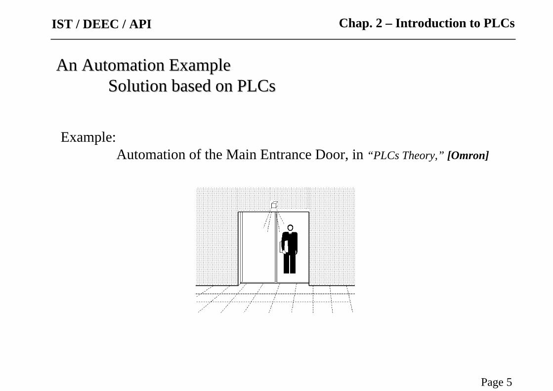
Example:Automation of the Main Entrance Door, in “PLCs Theory,” [Omron]
Chap. 2 – Introduction to PLCs

Page 6
IST / DEEC / API
Functional Specifications
An automatic system that could command the opening and close of a door is the main purpose of these specifications.
The command operation will be automatic and manual. There must be a selector with two positions in a front panel of command to select the mode of operation.
The manual mode resorts to the use of two push buttons to open and close the door. Once the OPEN push button is pressed, the door will be opened until the operation is completed, as detected by a limit switch. Upon pushing the CLOSE button the door will be commanded to close, until the end of the operation is detected by other limit switch.
The automatic mode of operation resorts to the use of two sensors, that detect the proximity of the users. When a person is detected the automatic opening of the door starts. The door remains open for a period from 5 to 20 seconds, following the null detection of the user. After that period the door starts to close. If during this last phase the presence of another user is detected the close operation is aborted and a new cycle of opening starts.
Chap. 2 – Introduction to PLCs
Example:Automation of the Main Entrance Door, in “PLCs Theory,” [Omron]
Page 7
IST / DEEC / API
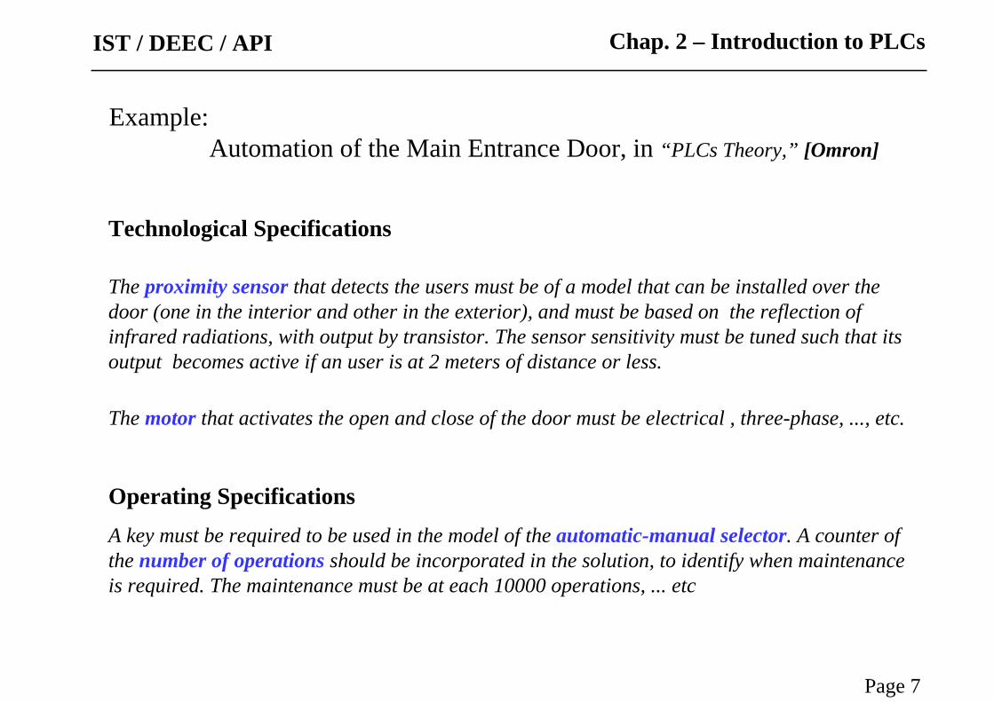
Technological Specifications
The proximity sensor that detects the users must be of a model that can be installed over the door (one in the interior and other in the exterior), and must be based on the reflection of infrared radiations, with output by transistor. The sensor sensitivity must be tuned such that its output becomes active if an user is at 2 meters of distance or less.
The motor that activates the open and close of the door must be electrical , three-phase, ..., etc.
Operating Specifications A key must be required to be used in the model of the automatic-manual selector. A counter of the number of operations should be incorporated in the solution, to identify when maintenance is required. The maintenance must be at each 10000 operations, ... etc
Chap. 2 – Introduction to PLCs
Example:Automation of the Main Entrance Door, in “PLCs Theory,” [Omron]

Page 8
IST / DEEC / API
Hardware list
Input (sensors):- Selector manual / automatic- Push button open door- Push button close door- Proximity sensors- Limit switch fully open- Limit switch fully closed
Chap. 2 – Introduction to PLCs
Example:Automation of the Main Entrance Door, in “PLCs Theory,” [Omron]
Output (actuators):- Motor actuation to open door- Motor actuation to close door
Combining all
- Connect input and output hardware- Implement functional and operational specifications, according to the technological specifications

Page 9
IST / DEEC / API
To use PLCS the connection to input devices (for detection and sensing) and to output devices (for command and control) is required.
A software program to implement the proposed solution has to be implemented in the PLC.
Automation Problems Automation Problems PLC based solutionsPLC based solutions
Chap. 2 – Introduction to PLCs
Process
ProgrammableLogic Controller
Sensors Actuators

Page 10
IST / DEEC / API
Architecture of Architecture of PLCsPLCs
Chap. 2 – Introduction to PLCs

Page 11
IST / DEEC / API
Memory Input/output
Central Processing Unit
Program
datacontrol
address
... and internally, how is it implemented?
Chap. 2 – Introduction to PLCs
Architecture of Architecture of PLCsPLCs

Page 12
IST / DEEC / API
Types of PLCs
Chap. 2 – Introduction to PLCs
Architecture of Architecture of PLCsPLCs
micro
mini
rack

Page 13
IST / DEEC / API
PLC
Chap. 2 – Introduction to PLCs
Architecture of Architecture of PLCsPLCs

Page 14
IST / DEEC / API
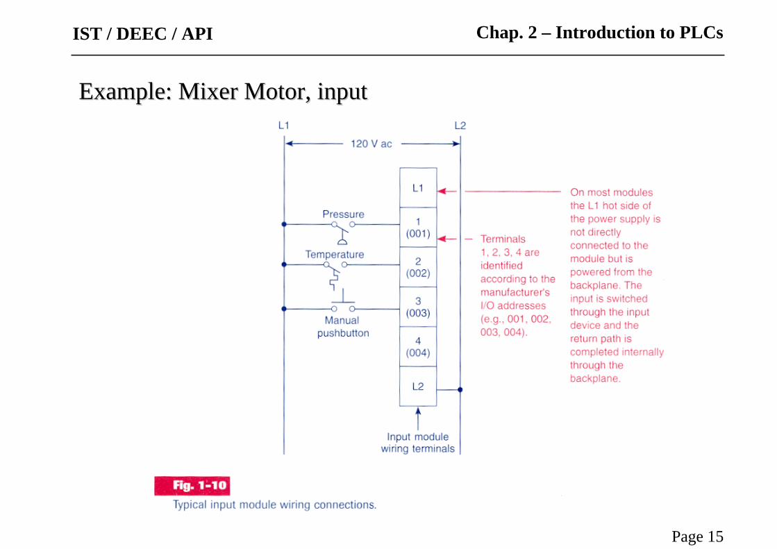
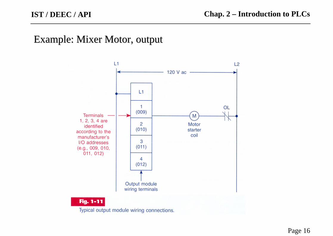
Problem [Petruzella96]: A mixer motor is to be used to automatically stir the liquid in a vat when the temperature and pressure reach preset values. In addition, direct manual operation of the motor is provided by means of a separate pushbutton station.
Solution using the relay diagram:
Example:Example: Mixer MotorMixer Motor
Chap. 2 – Introduction to PLCs
Page 15
IST / DEEC / API Chap. 2 – Introduction to PLCs
Example:Example: Mixer Motor, inputMixer Motor, input
Page 16
IST / DEEC / API Chap. 2 – Introduction to PLCs
Example:Example: Mixer Motor, outputMixer Motor, output

Page 17
IST / DEEC / API Chap. 2 – Introduction to PLCs
Example:Example: Mixer Motor, input + CPU/Memory + outputMixer Motor, input + CPU/Memory + output
PLC CPU and Memory

Page 18
IST / DEEC / API
Example:
Command of a motor from a consolewith start and stop buttons.
Chap. 2 – Introduction to PLCs
Internal structure and Internal structure and Work principlesWork principles

Page 19
IST / DEEC / API Chap. 2 – Introduction to PLCs
Internal structure and Internal structure and Work principlesWork principles

Page 20
IST / DEEC / API
Internal structure and Internal structure and Work principlesWork principles
Chap. 2 – Introduction to PLCs
2 4
1
3
5 1, 2, 3
3, 44, 5
Page 21
IST / DEEC / API
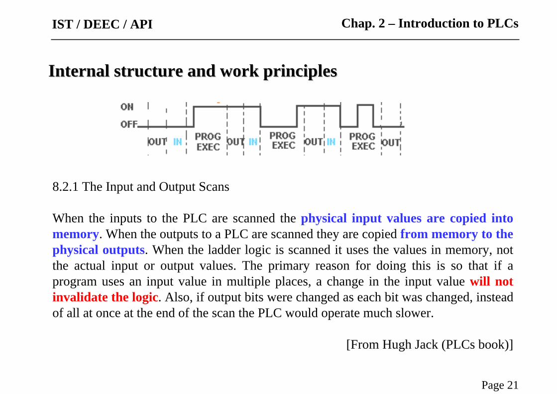
8.2.1 The Input and Output Scans
When the inputs to the PLC are scanned the physical input values are copied into memory. When the outputs to a PLC are scanned they are copied from memory to the physical outputs. When the ladder logic is scanned it uses the values in memory, not the actual input or output values. The primary reason for doing this is so that if a program uses an input value in multiple places, a change in the input value will not invalidate the logic. Also, if output bits were changed as each bit was changed, instead of all at once at the end of the scan the PLC would operate much slower.
[From Hugh Jack (PLCs book)]
Internal structure and work principlesInternal structure and work principles
Chap. 2 – Introduction to PLCs

Page 22
IST / DEEC / API
Scan Cycle, Scan Period
The inputs must be active for at least one scan cycle to have impact (no uncertainty) in the internal PLC state and indirectly in the outputs.
Exception: interrupts...
Chap. 2 – Introduction to PLCs
Internal structure and work principlesInternal structure and work principles

Page 23
IST / DEEC / API
Q: Worst time interval for an input to have impact on an output (with probability one)?
A: 2 * Scan Period
Q: Smallest time interval (with probability greater than zero) that the change in one input can impact in one output?
A: Scan Period – Read Time – Write Time = Execution Time
Chap. 2 – Introduction to PLCs
InternalInternal structurestructure andand workwork principlesprinciplesWorst time
Best time
Page 24
IST / DEEC / API
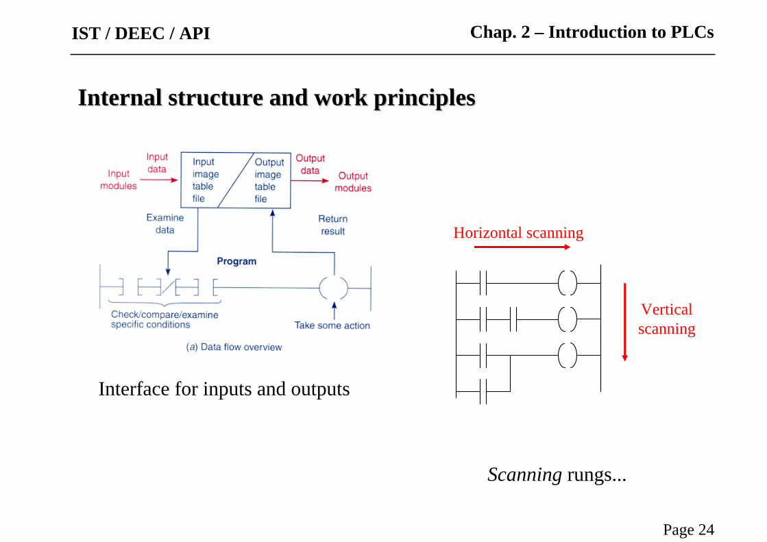
Scanning rungs...
Interface for inputs and outputs
Horizontal scanning
Verticalscanning
Chap. 2 – Introduction to PLCs
Internal structure and work principlesInternal structure and work principles

Page 25
IST / DEEC / API
8.2.2 The Logic Scan
Ladder logic programs are modeled after relay logic. In relay logic each element in the ladder will switch as quickly as possible. But in a program elements can only be examined one at a time in a fixed sequence. Consider the ladder logic in Figure 8.4, the ladder logic will be interpreted left-to-right, top-to-bottom. In the figure the ladder logic scan begins at the top rung. At the end of the rung it interprets the top output first, then the output branched below it. On the second rung it solves branches, before moving along the ladder logic rung.
[From Hugh Jack (PLCs book)]
Chap. 2 – Introduction to PLCs
Page 26
IST / DEEC / API
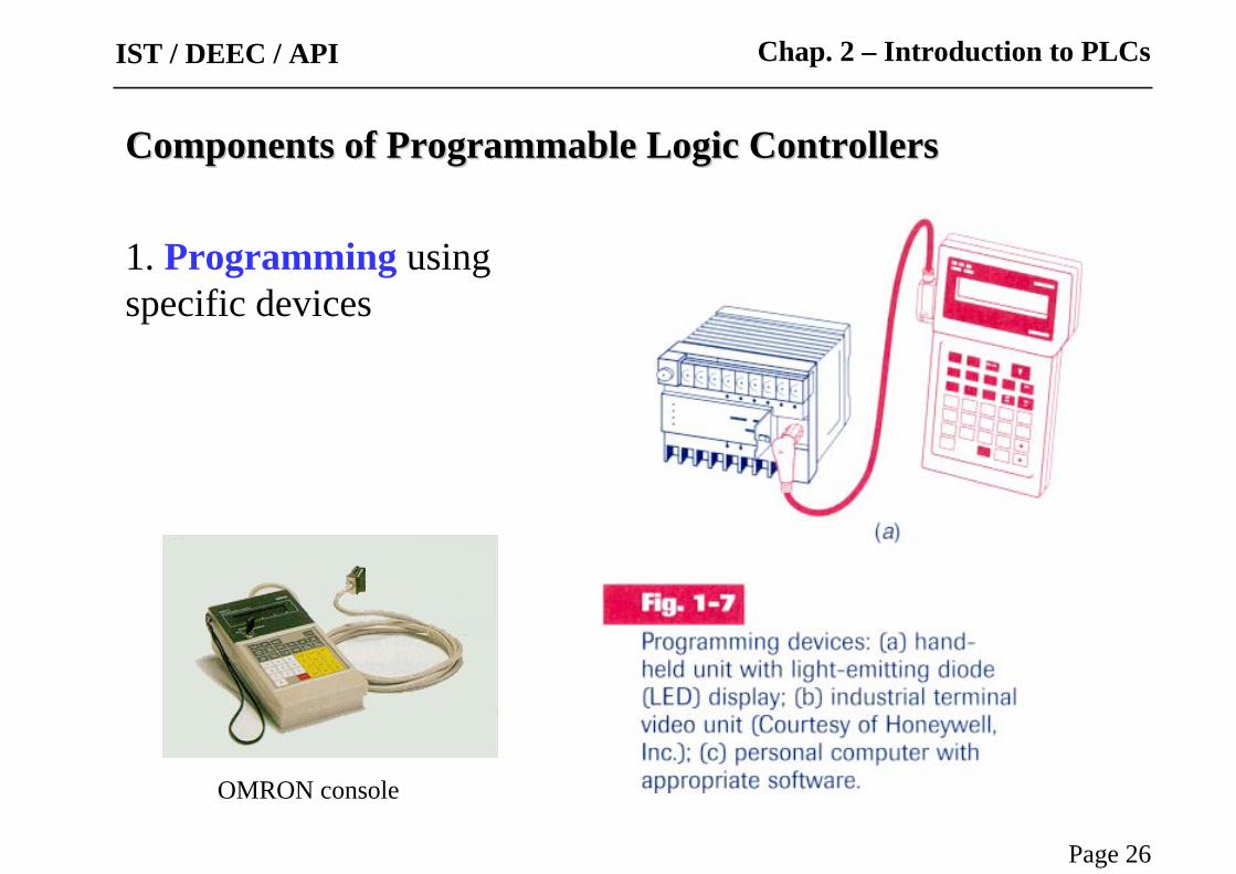
1. Programming usingspecific devices
OMRON console
Chap. 2 – Introduction to PLCs
Components of Programmable Logic Controllers Components of Programmable Logic Controllers
Page 27
IST / DEEC / API
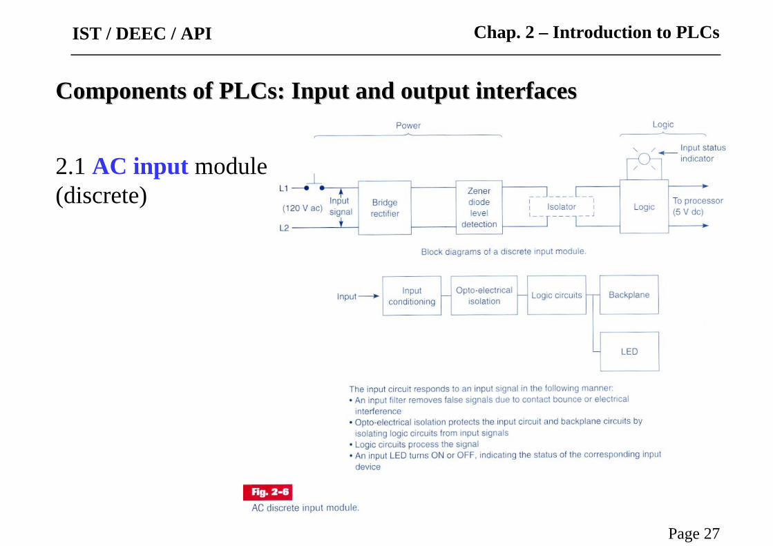
Components of Components of PLCsPLCs: Input and output interfaces: Input and output interfaces
2.1 AC input module(discrete)
Chap. 2 – Introduction to PLCs

Page 28
IST / DEEC / API
Components of Components of PLCsPLCs: Input and output interfaces: Input and output interfaces
2.1 AC input module:simplified implementation
Electronic circuit
Connections to the PLC terminals
Chap. 2 – Introduction to PLCs
Page 29
IST / DEEC / API Chap. 2 – Introduction to PLCs
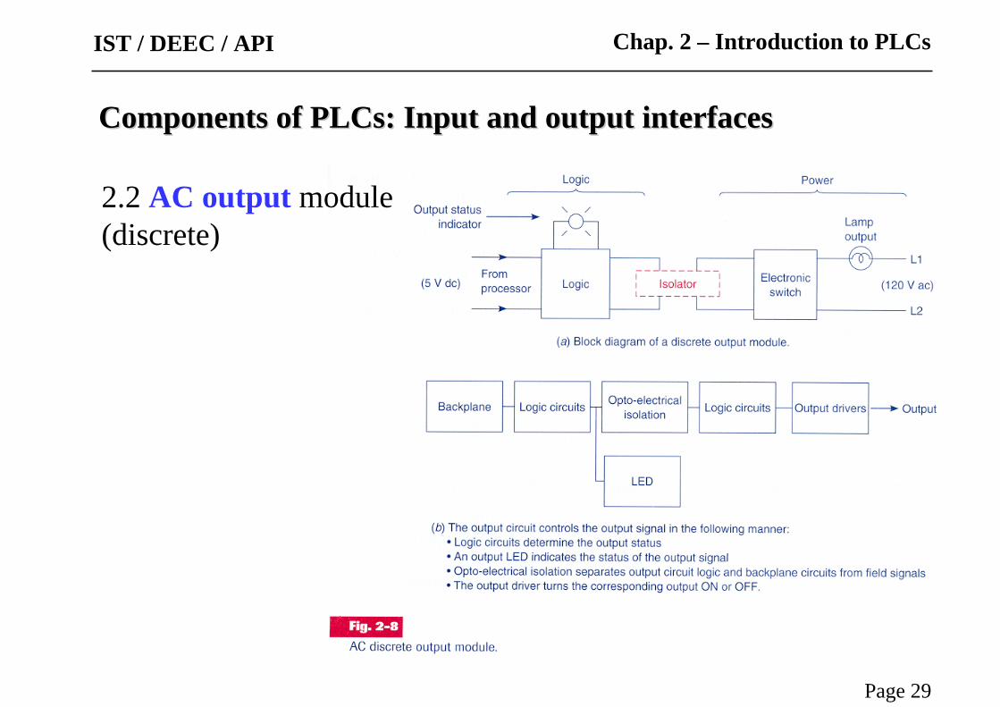
2.2 AC output module(discrete)
Components of Components of PLCsPLCs: Input and output interfaces: Input and output interfaces
Page 30
IST / DEEC / API Chap. 2 – Introduction to PLCs
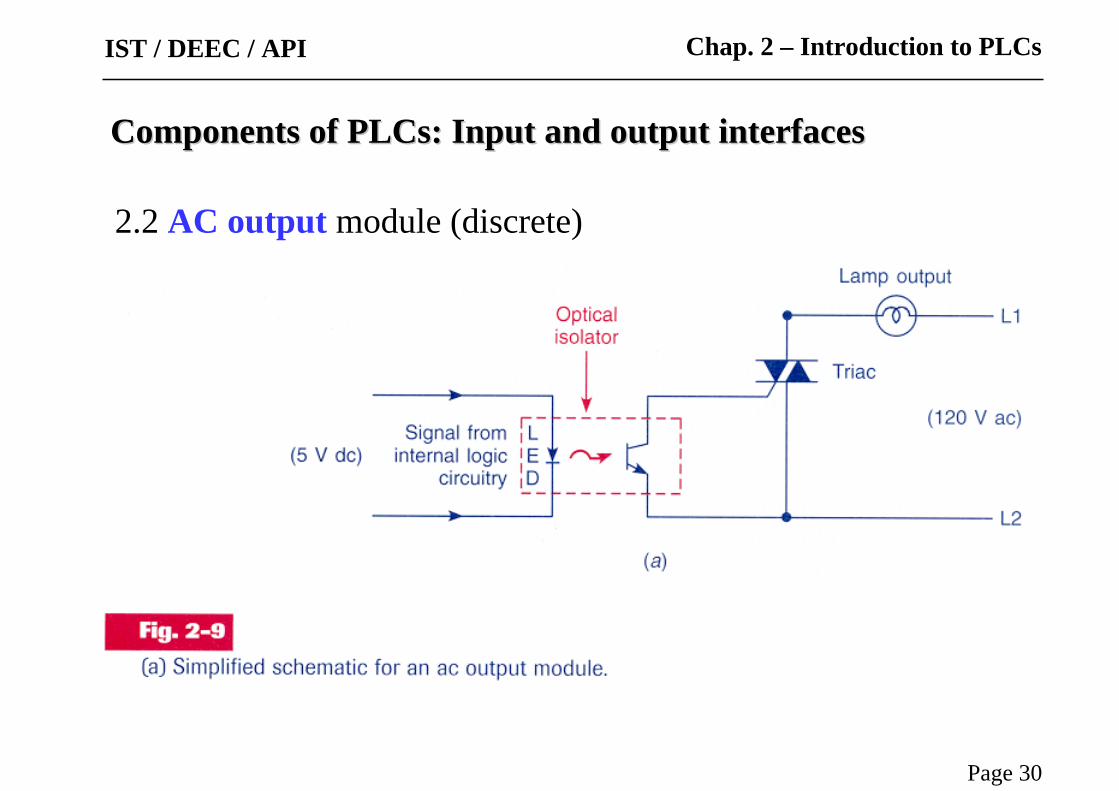
2.2 AC output module (discrete)
Components of Components of PLCsPLCs: Input and output interfaces: Input and output interfaces

Page 31
IST / DEEC / API
2.3 DC input module (discrete) Relay
Transistor
Opto-coupler
Attention to:• Galvanic isolation
• Economy
• Consumption
• Switching speed
• Noise immunity
Chap. 2 – Introduction to PLCs
Components of Components of PLCsPLCs: Input and output interfaces: Input and output interfaces
Externalterminals
Externalterminals
Externalterminals

Page 32
IST / DEEC / API
2.4 DC output module (discrete)
Relay
Transistor
... and protections.
Chap. 2 – Introduction to PLCs
Components of Components of PLCsPLCs: Input and output interfaces: Input and output interfaces
Externalterminals
Externalterminals
To theCPU
To theCPU
Connections to terminals ...
Externalterminals
Tothe
CPU

Page 33
IST / DEEC / API
3. Power sources
Switching power sources
Attention to:
• Isolation to the noise
• Isolation relative to disturbances on the network
• Efficiency
• Consumption
• Size (volume and weight)
• Robustness relative to load variations
Chap. 2 – Introduction to PLCs
Components of Programmable Logic Controllers Components of Programmable Logic Controllers


![Industrial Automation - ULisboausers.isr.ist.utl.pt/~jag/courses/api18b/docs/API_I_C2.pdf · Problem [Petruzella96]: A mixer motoris to be used to automatically stir the liquid in](https://img.dokumen.tips/doc/110x75/5e9e14911a6e5a3d6b72482f/industrial-automation-jagcoursesapi18bdocsapiic2pdf-problem-petruzella96.jpg)