Embed Size (px)
Citation preview

APEX TASK IProgress on MTOR Experiments for ALIST
Options
August 13, 2002APEX Electronic Meeting
Alice Ying, Mohamed Abdou, Jonathan Burris,Alex Ellias, Hulin Huang, Xiaoyong Luo,
Neil Morley, Tom Sketchley, and UCLA shopservices
Parameters of Interest and Scaling Requirements
Parameters of Interest NSTX M-TorFluid Operating Temperature (T) Density (ρρρρ) Electrical conductivity (σσσσ) Surface tension (γγγγ) Viscosity (µµµµ)
Lithium 225 oC485 kg/m3
2.83x10⁶ (ΩΩΩΩm)-1
0.325 N/m5.3x10-4 kgm/s
GaInSn35 oC6400 kg/m3
3.0x10⁶(ΩΩΩΩm)-1
0.533 N/m2.05x10-3 Kgm/s
Hartmann Factor (σσσσ/µµµµ)0.5 7.307x10⁴ 3.82x10⁴ (0.523)Reynolds Factor (ρρρρ/µ)µ)µ)µ) 9.15x10⁵ 3.12x10⁶ (3.41)Weber Factor (ρρρρ/γγγγ) 1492 12007 (8.047)Interaction Number (σσσσ/ρρρρ) 5835 468.75 (0.08)Field Strength Toroidal Poloidal Radial
0.318- 0.523 T0.144-(-0.011) T0.02 – (-0.04) T
0.6-0.2 T
Jet diameter (d)Jet velocity (V)Flow length (L)
5 mm10 m/s46 cm
5 mm 5 mm5 m/s 3 m/s45 cm 45 cm
Hartmann Number BTd(σσσσ/µµµµ)0.5 160.Reynolds Number ρρρρVd/µ µ µ µ 4.57x10⁴ 7.8x10⁴ 4.6x10⁴
Weber Number (ρρρρdV2222/γγγγ) Surface tension/gravity: γγγγ/ρρρρgL2
7463.38x10-4
1500 540
Interaction Number V
dB
ρσ 2
0.5648
!Increasing T by afactor of 2, M-Toris able toreproduce the LiHa under theNSTX conditions
!Flowing GaInSnat 3 m/s is able toreproduce theReynolds number
!The Webernumber can besimulated byflowing Gabetween 3 to 5m/s

Projected Schedule for M-Tor GaInSn ExperimentsAfter April Meeting
Decision:! Continue to Perform Jet Experiments until July! Transfer to Film Flow Experiments
Film Flow Experiments
May June July August September
Jet Flow Experiments
2-D Field Gradient Pole FaceDesign and Fabrication
Film Flow Test Article Design And Fabrication
1-D field gradient 2-D field gradient

Status of M-Tor Film Flow Experiments Not yet begin due to the Need to Choose the Proper Substrate
Material
" Previous film flow experiments used acrylic assubstrate material
GaInSn does not wet acrylic
" Liquid metal handbook indicates that Ga should wetMgO well
" MgO samples ordered and trieddid not behave as described in the handbook
" GaInSn appears to wet copper wellCurrent option ordered: platting copper onto acrylicsheet to give an insulted substrate (need an intermediate metallic layer)

Upgrades Since Last APEX Meeting
" Redesigned support structures for maximum current(field) operations
" Replaced Long Nozzle with a Short Nozzle Allows for breakup to occur further downstream No jet breakup found at jet inlet velocity of 5 m/s Breakup still observed at jet velocity less than 4 m/s
" Rebuilt liquid metal pump heat exchanger unit to allowfor longer operation times (cooling was not efficient inthe previous design)
" Reorganized loop drain section to minimize splashingand pulsation

Short Nozzle Should Deliver More Stable Jets
Outlet
"Turbulent jet breakup caused by amplification ofrandom fluctuation
Weber number for NSTX Li jetFlow length ~ 45 cmWe=298(2 mm jet at 10m/s)⇒⇒⇒⇒expected jet breakup within flowregimeWe=746(5 mm jet at 10 m/s)⇒⇒⇒⇒jet may not breakup
Expected breakup length based onPhinney’s correlation
0
10
20
30
40
50
60
0 200 400 600 800 1000 1200 1400 1600
Webe r Num ber
Bre
aku
pL
eng
th(c
m)
dWed
L085.155 +=
Experimental data points fromGaInSn runs
L= breakup lengthd = jet diameter
"A 5 mm jet should be considered forNSTX if it is feasible

Uses of Iron Flux Concentrators in M-tor to Generate 1- and 2-DTransverse Field Gradient Configurations
Twisted- tapered pole faceto produce 2-D (toroidal andsurface normal) fieldgradient
Tapered pole face toproduce 1-D (toroidal) fieldgradient
0.6 T
0.95 T
Test article setup
Nozzle
0.6 T , -0.026 T
1.12 T,-0.17 T

coil
0.6 T @3400 A
0.95 T @3400 A
M-Tor 1-DFieldConfiguration
M-Tor 2-DFieldConfiguration
(0.6, -0.026) Tat 3400 A
(1.12, -0.17) Tat 3400 A
M-Tor Experimental Setups with Iron Flux Concentrators
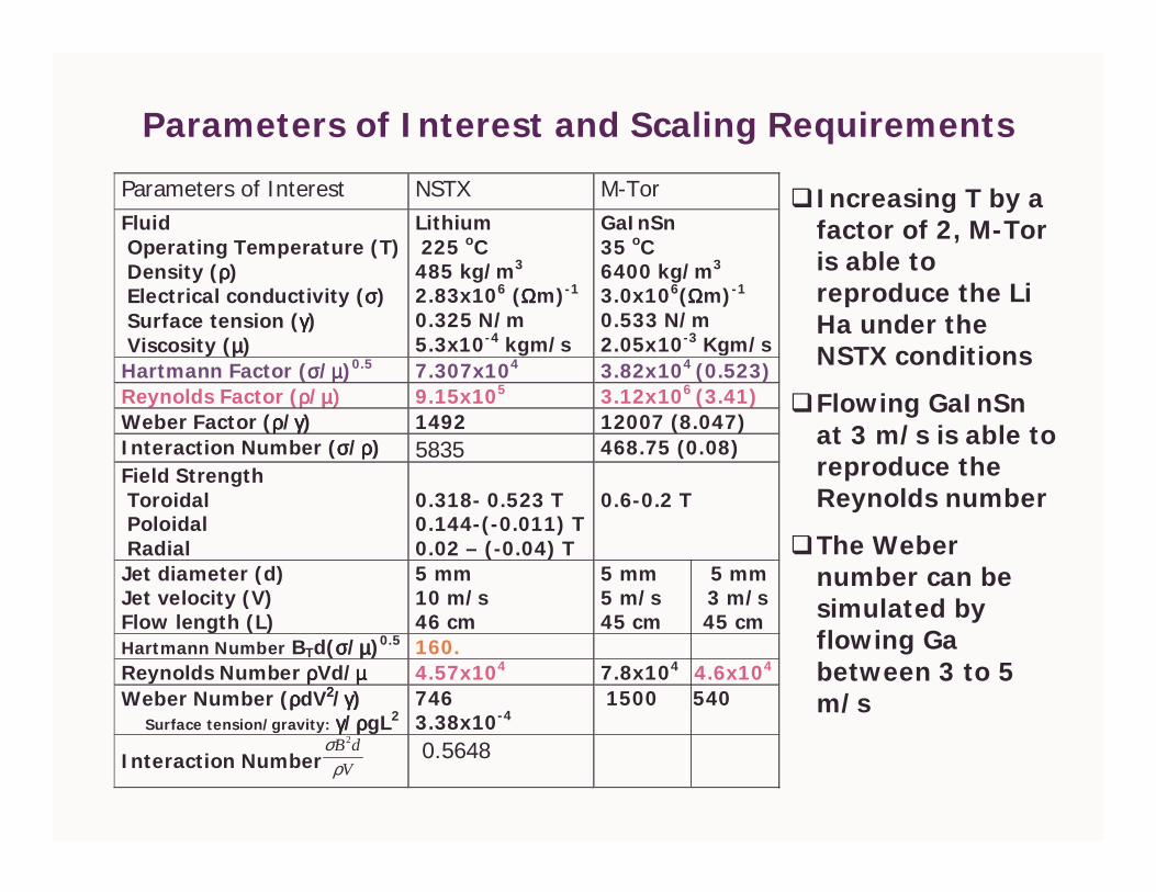
Characteristics of NSTX Fields and M-Tor Fieldswith Twisted/Tapered Poles
-2.5
-2
-1.5
-1
-0.5
0
0.5
1
1.5
2
2.5
0 0.5 1 1.5 2
R (m)
Z(m
)
Inlet
NSTXVessel
Surfacenormal field
Toroidalfield
NSTX
-0.4
-0.2
0
0.2
0.4
0.6
0.8
1
1.2
0 10 20 30 40 50
Distance from jet inle t (cm )
Fie
ldst
ren
gth
(T)
SimulatedToroidal field
Surface normalfield
By reversing the twist of the pole, wecan better replicate NSTX conditions
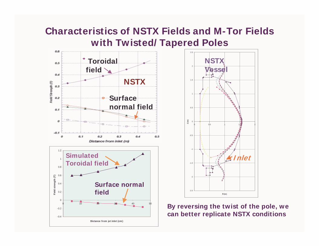
Experimental Results: Summary 1Front View Jet Images (1-D field gradient)
1. The NSTX like magnetic field strength has significantlystabilized the jet by suppressing velocity perturbations
0 A 0 A3400 A 3400 A
GaInSn inlet velocity = 5 m/s12 inches downstream 22 inches downstream
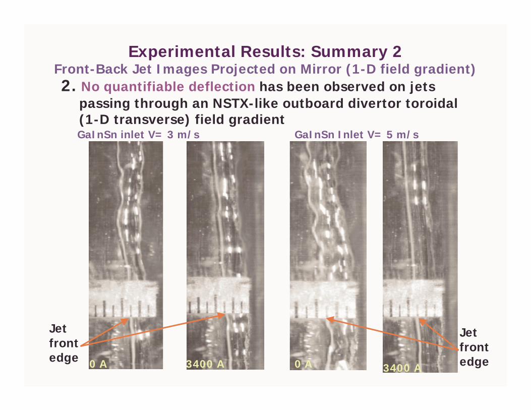
Experimental Results: Summary 2Front-Back Jet Images Projected on Mirror (1-D field gradient)2. No quantifiable deflection has been observed on jets
passing through an NSTX-like outboard divertor toroidal(1-D transverse) field gradientGaInSn inlet V= 3 m/s
0 A 3400 A
Jetfrontedge
GaInSn Inlet V= 5 m/s
0 A 3400 A
Jetfrontedge

Experimental Results: Summary 3 Front View Jet Images (1-D transverse field gradient)
3. The stabilizing effect of the magnetic field results indelaying jet breakup
0 A 1000 A 2000 A 3400 A
(This is evident from the pictures shown below, although in the present setup thefield strength is not strong enough to quantify the amount of increase in breakuplength)
GaInSn- 3 m/s
breakup

Experimental Results: Summary 4 Front View Jet Images (2-D field gradient)
4. The stabilization effect remains the same under 2-Dtransverse field gradientsInlet velocity =3 m/s
0 A 3400 A 3400 A0 A
Inlet velocity= 5 m/s

Experimental Results: Summary 5 Front-Back Jet Images Projected on Mirror (2-D field gradient)
5. No obviously quantifiable deflection has been observedon jets passing through 2-D transverse (toroidal +surface normal ) field gradients
3 m/s0 A
3 m/s3400 A
5 m/s0 A
5 m/s3400 A
28 cm downstream
Frontedge

NSTX Modeling Status(Based on FLOW-3D Approach)
Since April, 2002---! In an attempt to speed up calculations, the ADI
method (line iteration) was applied to replace thepreviously used Gauss-Seidel (point iteration)numerical scheme.
! Unfortunately, after several weeks of computations,we discovered that the results based on the ADI(alternative direction iteration) method show less 3-DMHD effects than that of the Gauss-Seidel’s method.
! Effort is underway to resolve the source of thisproblem.
Before April, 2002---" Numerical simulation provided guidance to
experimental investigations (and concluded thatdeflections observed under 1-D transverse fieldconditions occurred only when the field is changing).


![mTOR signaling in kidney diseases...Sep 03, 2020 · The mTOR pathway regulates cell growth, proliferation, survival and metabolism [4]. Dysregulation of mTOR signaling disrupts renal](https://img.dokumen.tips/doc/110x75/608faa7a471c847b5d397b8c/mtor-signaling-in-kidney-diseases-sep-03-2020-the-mtor-pathway-regulates.jpg)