Embed Size (px)
Citation preview

Atacama PathfinderEXperiment
Interface Control Document
APEX-MPI-ICD-0003
Revision: 0.5
Release: September 6, 2002
Category: 4
Author: D. Muders
APEX Standard HardwareInterfaces
Dirk Muders
Keywords:
Author Signature: D. Muders Date: September 6, 2002
Approved by: NN
Institute: NNN
Signature: NN
Date: Month Date, Year
Released by: NN
Institute: NNN
Signature: NN
Date: Month Date, Year

APEX Standard Hardware Interfaces APEX-IFD-MPI-0003
Page 2 of 16 Issue: 0.5
Change Record
DATE AUTHOR SECTIONS/PAGES AFFECTED REVISION REMARKS
May 2002 D. Muders All 0.0 Initial version 8/28/2002 D. Muders Instrument control systems
Digital signals 0.5
Describe standard instrument control system after meeting in Bonn. New Blank/Sync pinout including strobe signal. Connector definitions.
APEX-IFD-MPI-0003 APEX Standard Hardware Interfaces
Issue: 0.5 Page 3 of 16
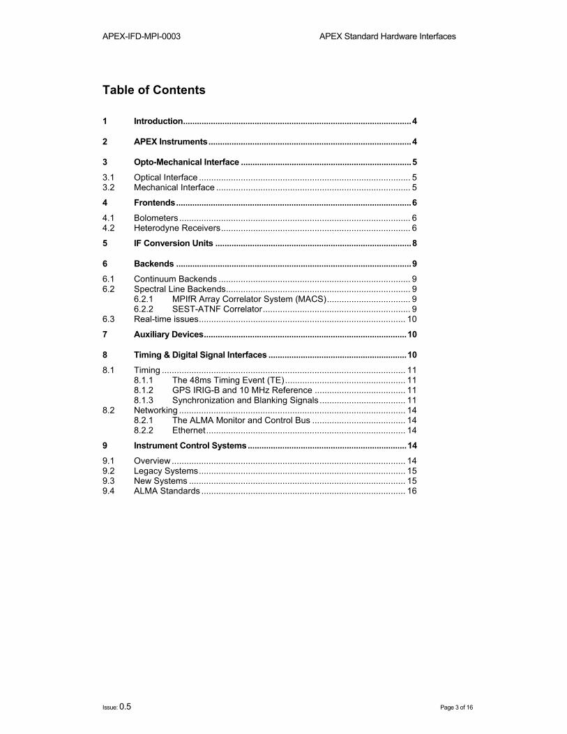
Table of Contents 1 Introduction...................................................................................................4
2 APEX Instruments........................................................................................4
3 Opto-Mechanical Interface ..........................................................................5 3.1 Optical Interface ...................................................................................... 5 3.2 Mechanical Interface ............................................................................... 5 4 Frontends......................................................................................................6 4.1 Bolometers .............................................................................................. 6 4.2 Heterodyne Receivers............................................................................. 6 5 IF Conversion Units .....................................................................................8
6 Backends ......................................................................................................9 6.1 Continuum Backends .............................................................................. 9 6.2 Spectral Line Backends........................................................................... 9
6.2.1 MPIfR Array Correlator System (MACS).................................. 9 6.2.2 SEST-ATNF Correlator............................................................ 9
6.3 Real-time issues.................................................................................... 10 7 Auxiliary Devices........................................................................................10
8 Timing & Digital Signal Interfaces ............................................................10 8.1 Timing ................................................................................................... 11
8.1.1 The 48ms Timing Event (TE)................................................. 11 8.1.2 GPS IRIG-B and 10 MHz Reference ..................................... 11 8.1.3 Synchronization and Blanking Signals ................................... 11
8.2 Networking ............................................................................................ 14 8.2.1 The ALMA Monitor and Control Bus ...................................... 14 8.2.2 Ethernet................................................................................. 14
9 Instrument Control Systems.....................................................................14 9.1 Overview ............................................................................................... 14 9.2 Legacy Systems.................................................................................... 15 9.3 New Systems ........................................................................................ 15 9.4 ALMA Standards ................................................................................... 16

APEX Standard Hardware Interfaces APEX-IFD-MPI-0003
Page 4 of 16 Issue: 0.5
1 Introduction This document defines the standard hardware interfaces (opto-mechanical, electrical and control system hardware) for APEX instruments (= Frontends, IF conversion units, Backends, Timing, Digital Signal & Synchronization Equipment and Auxiliary Devices). The standard software interface for these devices is defined in a separate document (“Software Interfaces for Submillimeter Telescope Instrumentation”, D. Muders et al., published under “ALMA Technical Notes” at http://www.alma.nrao.edu/development/computing/docs/ (NB: this report needs an update concerning the Auxiliary Devices).
The main antenna control system is not discussed here. Being a clone of the US ALMA prototype, APEX shares the CAN Bus interface and can thus use the software that is currently being developed for the ALMA Test Interferometer in Socorro (ALMA Common Software (ACS) and ALMA Test Interferometer Control Software (TICS)) without modifications. Only the instruments differ from the ALMA setup and there is a need to define the hard- and software interfaces for the APEX specific devices. Nevertheless, we will try to stay as compatible as possible with ALMA in order to profit from their large development teams.
2 APEX Instruments Initially, there will be first light instruments used for holography and pointing during the antenna commissioning / testing phase. Later, facility instruments for the APEX community will replace most of them.
Band RF-Range (µm) First Light APEX-1 1300/870 single channel bolometer for commissioning APEX-2 350 37-element camera for 350 µm atm. window APEX-3 870 Large Bolometer Camera (LABOCA): late 03
300 elements for 870 µm atm. window Table 2-1 and Table 2-2 summarize the bolometer and heterodyne instruments for APEX. A number of the APEX instruments already exist and are currently used at other telescopes (e.g. the SEST 1mm receiver, the SEST-ATNF autocorrelator, the CHAMP array and the MACS autocorrelator). Some of the instruments already have modern control systems such as the VME based system for CHAMP. Time and manpower constraints will not allow modifying all existing instrument control systems and interfaces. The standards for new instruments will thus partly be derived from existing instruments. The interface definition is also driven by the usage of the TICS & ACS. For a native ACS implementation without a software interface wrapper, new control systems must use Linux or VxWorks. Linux is somewhat preferred, as ALMA wants to drop VxWorks completely. But a decision by ALMA is not expected within the time scales for upcoming APEX developments.
Band RF-Range (µm) First Light APEX-1 1300/870 single channel bolometer for commissioning APEX-2 350 37-element camera for 350 µm atm. window APEX-3 870 Large Bolometer Camera (LABOCA): late 03
300 elements for 870 µm atm. window Table 2-1: APEX bolometers.
Linux should be used for all non-time-critical systems such as a frontend and IF control systems. Real-time systems such as backends (due to time stamping and synchronization to wobbler and frequency switching signals) must use VxWorks and the standard ALMA hard- and software (i.e. VME64x crates, MVME 2700 CPUs, VxWorks 5.4 etc.; see “ALMA Software and Hardware Standards” draft at http://www.alma.nrao.edu/) to ensure compatibility with TICS & ACS.

APEX-IFD-MPI-0003 APEX Standard Hardware Interfaces
Issue: 0.5 Page 5 of 16
Band RF-Range IF [GHz]
DSB Noise
First Light Final Config.
APEX-1 G: 211-275 4-8 G: 25 K B: <40 K
Onsala: SEST 230 GHz Onsala Q3 2004 LO from/via MPIfR (tbc)
APEX-2 G: 275-370 4-8 G: 35 K B: <50 K
Onsala: in new CC-cryostat (LO ?) Q3 2003
APEX-3 G: 375-500 B: 455-500
4-8 G: 70 K B: tbd
Baseline I: Baseline II: MPIfR: CHAMP mixer in dual channel cryostat Q3 2003
Baseline I: MPIfR: CHAMP Q3 2004 Baseline II (goal): Onsala: dual polarisation CC. LO from/via MPIfR (tbc) Q3 2004
APEX-4 G: 602-720 4-8 G: 110 (H) G: 170 (A)
APEX-5 G: 787-950 4-8 G: 175 K B: tbd
Baseline I: MPIfR: SRON mixers in dual-channel cryostat Q3 2003
Baseline I: First-light mixers in CC Q3 2004 (tbc) Baseline II (goal): MPIfR: CHAMP(+) Q4 2004
APEX-T1 G: 1030 (50) 4-8 G: 230 K APEX-T2 G: 1320 (140) Tbd G: 550 K APEX-T3 G: 1500 (140) Tbd G: 650 K
PI-Instruments
Table 2-2: APEX heterodyne receivers.
3 Opto-Mechanical Interface This section defines the optical and mechanical interfaces for all APEX frontends. It is currently not yet well defined and detailed are discussions needed.
3.1 Optical Interface
Issues: • Subreflector (Shape TBD: E. Kreysa, T. Klein) • Refocusing optics / Imaging (TBD: E. Kreysa, T. Klein) • Tertiary mirror • Mirrors for calibration loads
3.2 Mechanical Interface
Issues: • Bolometer array mount (TBD, E. Kreysa) • Heterodyne single pixel mount (TBD, R. Güsten, R. Booth) • Heterodyne array (CHAMP) mount (TBD, R. Güsten, C. Kasemann) • Calibration loads (ambient, cold (LN2)) (C. Kasemann, G. Schneider, E. Kreysa, T. Klein) • Door openings / sizes (Defined; details from G. Schneider) • Crane (Defined; details from G. Schneider)

APEX Standard Hardware Interfaces APEX-IFD-MPI-0003
Page 6 of 16 Issue: 0.5
4 Frontends
4.1 Bolometers All bolometer cameras will be mounted in the Cassegrain focus cabin. The Monitor & Control (M&C) interface for traditional semiconductor-based bolometers is minimal (often nothing, sometimes an amplifier setting which is often integrated into the continuum backend). If future bolometers (LABOCA) use SQUIDs, a more elaborate hard- and software interface might be needed for the SQUID setup if one cannot use the automatic SQUID tuning electronics (TBD with E. Kreysa and the IPHT group in Jena).
4.2 Heterodyne Receivers The Onsala Space Observatory and the MPIfR supply the APEX heterodyne receivers (see Table 2-2). They are mounted in the two Nasmyth cabins. Facility receivers are set up in cabin A, the CHAMP array will be mounted in cabin B (the only exception will be the first light 1mm receiver from the SEST telescope that will be set up in the Cassegrain cabin). The standard IF range for the frontend output will be 4-8 GHz at a TBD output level. There are basically two existing receiver control systems:
1. The SEST / Onsala system currently used for the SEST receivers. It is based on an STE bus system. Communication with this system is set up via raw Ethernet packets. It is not possible to use it as-is. M. Anciaux has proposed to upgrade it for APEX. If any new system is developed, then it should become the standard for all receivers. A detailed discussion about the hardware choices and design is currently going on.
2. The MPIfR CHAMP system uses VME hardware (see Error! Reference source not found.) with IP modules (digital & analog I/O, PT100 inputs) and Windows 2000 as operating system. Communication is set up via a TCP/IP socket protocol. A similar system has been built for monitoring of the central APEX compressors and chillers (see 7). The hardware of these systems is up-to-date. For a native ACS implementation, the operating system would need to be changed to Redhat Linux 7.2. However, the Windows 2000 system has been successfully used for a couple of years at the CSO.

APEX-IFD-MPI-0003 APEX Standard Hardware Interfaces
Issue: 0.5 Page 7 of 16
The MPIfR receiver control system also includes a modern remote controllable analog bias box that was developed for the GREAT receiver on SOFIA (see Figure 4-1). It can be used for mixer, cold amplifier and magnetic field biases and also for multipliers in LO chains. The bias box is controlled from the usual VME systems via IP modules (see Figure 4-2). A local panel with displays and controls can be connected instead of the VME crate when working in the receiver cabins.
Figure 4-1: Remote controllable analog bias box developed by the MPIfR for the GREAT receiver on SOFIA. This box can be used for mixer bias, B-field, cold amplifier and LO chain multipliers. A local panel with displays is available for work in the receiver cabins.
Figure 4-2: The frontend VME system also controls the MPIfR analog bias box.
B-Field Mixer Heater
Mixer Bias
4 Stage IF-Amplifier
Bias
Temperature Control
FrontendVME System
PreAmp
APEX Standard Hardware Interfaces APEX-IFD-MPI-0003
Page 8 of 16 Issue: 0.5
Issues: • Synthesizer control (Rhode & Schwartz) via GPIB bus hooked up directly to the VME
telescope control computer or via CAN Bus ? • Doppler correction preferably via 2-20 GHz synthesizer rather than the 100 MHz PLL
reference synthesizer because the latter will go away when using photonic LOs.
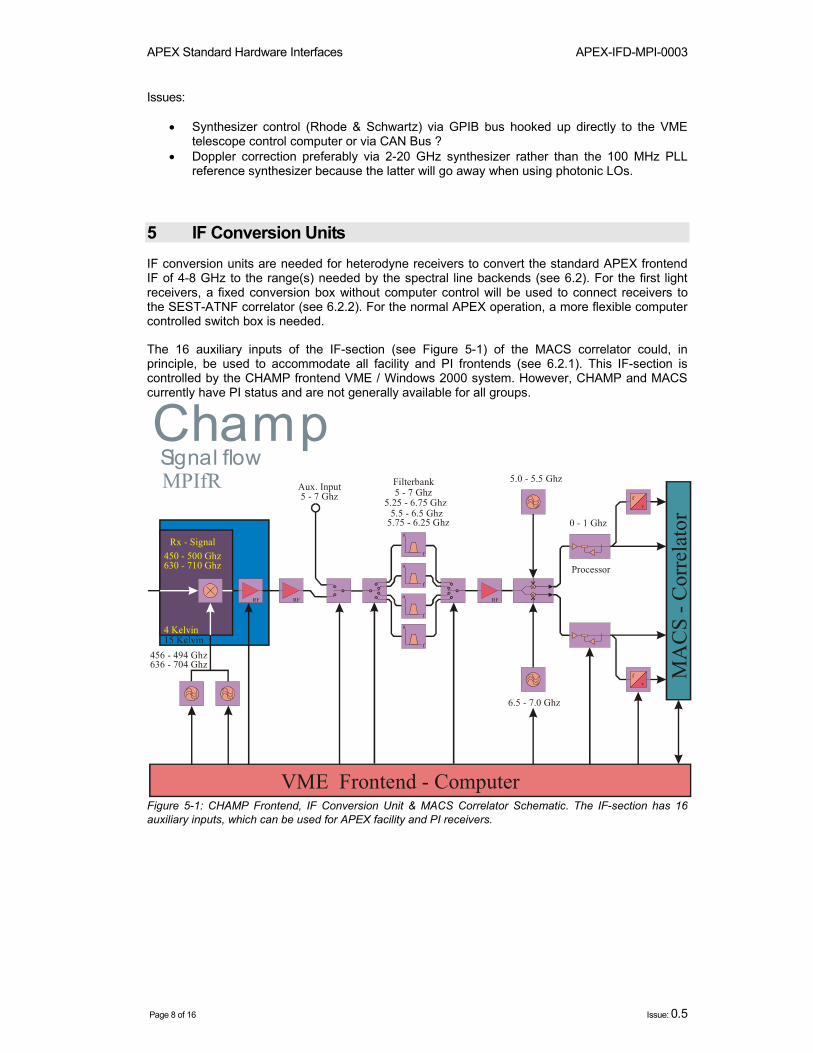
5 IF Conversion Units IF conversion units are needed for heterodyne receivers to convert the standard APEX frontend IF of 4-8 GHz to the range(s) needed by the spectral line backends (see 6.2). For the first light receivers, a fixed conversion box without computer control will be used to connect receivers to the SEST-ATNF correlator (see 6.2.2). For the normal APEX operation, a more flexible computer controlled switch box is needed.
The 16 auxiliary inputs of the IF-section (see Figure 5-1) of the MACS correlator could, in principle, be used to accommodate all facility and PI frontends (see 6.2.1). This IF-section is controlled by the CHAMP frontend VME / Windows 2000 system. However, CHAMP and MACS currently have PI status and are not generally available for all groups.
RF RF RF
VME Frontend - Computer
MA
CS
- Cor
rela
tor
ChampSignal flowMPIfR
f
a
f
a
f
a
f
a
fv
fv
0 - 1 Ghz
5.25 - 6.75 Ghz5.5 - 6.5 Ghz
5.75 - 6.25 Ghz
5 - 7 Ghz
15 Kelvin
5.0 - 5.5 Ghz
6.5 - 7.0 Ghz
636 - 704 Ghz
450 - 500 GhzRx - Signal
4 Kelvin
Filterbank
Processor
Aux. Input5 - 7 Ghz
630 - 710 Ghz
456 - 494 Ghz
Figure 5-1: CHAMP Frontend, IF Conversion Unit & MACS Correlator Schematic. The IF-section has 16 auxiliary inputs, which can be used for APEX facility and PI receivers.

APEX-IFD-MPI-0003 APEX Standard Hardware Interfaces
Issue: 0.5 Page 9 of 16
6 Backends
6.1 Continuum Backends
The APEX continuum backend will be a clone of the so-called “ABBA” backend, which is in use at the IRAM 30m telescope. It is based on a commercial 64-channel PCI ADC card. The version for APEX will offer at least 300 input channels and it will be operated under Redhat Linux 7.2 with a native ACS implementation. The system is currently being designed and built at the MPIfR and the University of Bochum under the lead of R. Lemke.
6.2 Spectral Line Backends 6.2.1 MPIfR Array Correlator System (MACS)
MACS and its IF distribution system were built by the MPIfR digital and submm labs for the CHAMP heterodyne array. Due to signal conditioning (levels, etc.), the two units must be used together. The IF distribution unit provides an auxiliary input, which can accommodate 16 channels at 5-7 GHz at a TBD level.
MACS is currently in use with CHAMP at the CSO submillimeter telescope. It will return to the MPIfR in 2003. After upgrading a number of components (in MACS itself and in the IF system), it will be shipped to APEX and become the main spectral line backend for all receivers. The IF-section will be used to connect the facility and PI receivers to MACS.
The MACS control system runs on a VME computer under VxWorks 5.2. Currently, MACS is controlled via a socket interface. Bulk data is written to an output file. For APEX, the control system must either be upgraded to VxWorks 5.4 using an MVME 2700 CPU, or the socket interface must be upgraded to comply with the APEX socket standard that is currently being defined (Muders, Ibsen, Lopez, et al.).
MACS Hardware Interface:
• MACS Input: 0-1 GHz (not directly accessible) • Level: 0 dB • IF (CHAMP and AUX) input: 5-7 GHz • Level: TBD (C. Kasemann) • Connector: N-type
6.2.2 SEST-ATNF Correlator
The SEST-ATNF correlator was built by the ANTF group under Warwick Wilson. It is currently in use at the SEST telescope and will be transferred to APEX in 2003. This correlator will be the spectral line backend during the first 1-2 years of APEX operation. To connect receivers, a down-converter box with fixed center frequencies and without computer control will be used.
A PC under Redhat Linux 5.2 currently controls the SEST-ATNF Correlator. Socket interfaces are used to communicate with the correlator and to send bulk data. To interface this correlator with TICS / ACS, either the Linux needs to be upgraded to Redhat version 7.2 and ACS must be installed, or the socket interface must be upgraded to comply with the APEX socket standard.
SEST-ATNF Correlator Hardware Interface:
• Inputs: o 0-1024 MHz (baseband) o 512-1024 MHz (lower sideband)

APEX Standard Hardware Interfaces APEX-IFD-MPI-0003
Page 10 of 16 Issue: 0.5
o 512-768 MHz (upper sideband) o 128-256 MHz (lower sideband) o 128-192 MHz (upper sideband)
• Level: 0 dB • Connector: ?
6.3 Real-time issues
• Time stamps: All backend data need an exact time stamp (see 8.1) • Blank & Synch: All backends must be able to synchronize themselves to the common
blank and synch signals (see 8.1.3). Data for the individual phases must be stored separately.
• Data format and access: Binary encoded streams / files with timestamp, number of phases, integration time and bulk data. Format TBD (Muders, Lemke, Klein, Lerner)
7 Auxiliary Devices There are a number of auxiliary devices that need a hard- and software interface too. So far, we have the blank/sync generator (see section 8.1.3), the central synthesizers and the frontend compressors and central chillers, which will all be located on a platform below the correlator container. Commonly used connectors (Details needed from G. Schneider) for helium lines, water pipes, etc. define the hardware interface standard. A software monitoring system based on the VME / Windows 2000 system that is used for the CHAMP array control (see 4.2) has already been developed by G. Schneider. To interface it with the TICS / ACS software, one can either encapsulate the existing socket communication layer or change the operating system to Redhat Linux 7.2 and use a direct ACS implementation.
Another auxiliary system is the chopping secondary. The vendor (VERTEX) will supply the control system (within the PTC). We need to specify the interface (close to the ALMA Nutator ICD). We want to stay compatible with ALMA, but our requirement of synchronizing the wobbler with external blank/sync signals may collide with ALMA specifications.
8 Timing & Digital Signal Interfaces Digital signals for APEX are comprised mainly of timing signals such as the GPS IRIG-B signal or the ALMA 48ms Timing Event (see below) and of synchronization and blanking signals used for observing modes such as wobbling or frequency switching. In addition, the 10 MHz reference signal from GPS is needed for oscillator locking. Apart from these signals one also needs network connections (Ethernet and CAN Bus). All digital signals should be available throughout the telescope, i.e. in all 3 receiver cabins and in the correlator and control room containers. Table Table 8-1 summarizes all signals, their format, the medium and the standard connectors:
The pinout of the CAN bus connector is described in ALMA computing memo number 7 (see http://www.alma.nrao.edu/development/computing/docs/memos). The CAN bus will be made available via male 9 pin SUB-D connectors.

APEX-IFD-MPI-0003 APEX Standard Hardware Interfaces
Issue: 0.5 Page 11 of 16
Signal Format Medium Connector
CAN Bus (AMB) / 48ms TE RS485 Twisted pair 9 pin SUB-D / 9 pin DIN
GPS IRIG-B Frequency Coaxial cable BNC
GPS 10 MHz Reference Frequency Coaxial cable BNC Synchronization / Blanking / Phase encoding RS422 Twisted pair 15 pin SUB-D
Ethernet 100 Mbps / 1000 Mbps
Twisted pair / Fiber RJ-45 / ST / SC
Table 8-1: Standard APEX digital signals.
8.1 Timing 8.1.1 The 48ms Timing Event (TE)
ALMA uses a 48ms Timing Event (TE) signal derived from the master clock (GPS, Maser, etc.) to provide timing and synchronization. The TE signal is a differential RS485 signal transmitted via the ALMA Monitor and Control Bus (a modified version of the CAN Bus interface; see 8.2.1). The TE is needed for the CAN bus communication with the VERTEX Antenna Control Unit (ACU). Commands are sent in the first 24ms, replies are expected in the second 24ms. The TE is also used by the Test Interferometer Control Software (TICS) Time Service to provide the absolute time to devices that need it (e.g. for accurate time stamping in backends). To get the time, the device sends a request to the Array Real Time Machine (ARTM, a VME computer running VxWorks) and asks for the time. The ARTM must reply before the next TE for the result to be valid, otherwise the request must be repeated. This should be the standard method to obtain the time for APEX devices. However, to use this service, the device must use the ALMA/Advanced Common Software (ACS) and possibly TICS, which are currently available only for VxWorks, Linux and Solaris. For some devices it may be too complicated to use that software. They should obtain the absolute time via the IRIG-B signal (see 8.1.2).
8.1.2 GPS IRIG-B and 10 MHz Reference
The GPS station clock will provide the absolute time encoded in the IRIG-B signal and a 10 MHz reference signal to lock oscillators. Both signals can be distributed via BNC cables. An advantage of IRIG-B over the TICS Time Service is that almost any device could use this service via an IRIG-B decoder card and one would not have to use ACS/TICS. However, those cards are quite expensive and their use is discouraged since we already have the TE signal (see 8.1.1).
8.1.3 Synchronization and Blanking Signals
For some observing modes (e.g. wobbling, frequency switching) external synchronization and blanking signals (SBS) are needed. The synchronization signal defines phase times for the integration under certain conditions (wobbler left/right, upper/lower frequency 1/2). The blanking signal is used to blank the transition times (wobbler moves to other position, PLL locks receivers at other frequency).
The SBS must be generated centrally under software control. The MPIfR digital group has developed such generators for other projects (VME card (used for example in the MACS correlator or the new standalone SBS generator with an RS232 interface). A special version will be developed to provide the signals for APEX. It also includes a strobe signal which is used to

APEX Standard Hardware Interfaces APEX-IFD-MPI-0003
Page 12 of 16 Issue: 0.5
detect when all other signals are valid. This avoids problems with time jittering. Figures xxx and yyy show the timing diagram for the cases of having 1 and 4 phases.
The SBS will be first routed from the generator to critical devices, which can increase the commanded blanking time according to their needs (e.g. the PLL takes more time to lock). Only then the signal should be routed on to the backends, which use them to decide where to store the data for the phases. The block diagram in Figure 8-1 shows this setup.
Figure 8-1: Synchronization and blanking signal generation and distribution.
The SBS will be differential according to the RS422 standard to avoid signal degradation when distributing it throughout the telescope. Being a uni-directional bus, RS422 also makes it easy to hook up many devices. In addition to the two timing signals it is desirable to encode the phase number digitally. This avoids decoding problems in the backends. The typical maximum number of phases at existing telescopes ranges from 2 to 16. This signal should also use the RS422 protocol since it will be distributed from the correlator container where the SBS generator will be located to at least the Cassegrain cabin, which is too far away to use TTL signals.

APEX-IFD-MPI-0003 APEX Standard Hardware Interfaces
Issue: 0.5 Page 13 of 16
The pinout of the Synchronization / Blanking / Phase encoding and Strobe signals has been defined as shown in Table 8-2. Those signals will be made available via female 15 pin SUB-D connectors.
Pin number Function
1 Negative Synchronization Signal 9 Positive Synchronization Signal 2 Negative Blanking Signal
10 Positive Blanking Signal 3 Negative Bit 0 of Phase encoding
11 Positive Bit 0 of Phase encoding 4 Negative Bit 1 of Phase encoding
12 Positive Bit 1 of Phase encoding 5 Negative Bit 2 of Phase encoding
13 Positive Bit 2 of Phase encoding 6 Negative Strobe Signal
14 Positive Strobe Signal 15 GND 8 Optional +5V (current limited to 100mA)
Table 8-2: Pinout of the Synchronization / Blanking / Phase encoding signals
Figure 8-2 and Figure 8-3 show the timing diagrams for the case of 1 and 4 phases.
Figure 8-2: Synchronization, blanking and strobe signal timing diagram for 1 phase

APEX Standard Hardware Interfaces APEX-IFD-MPI-0003
Page 14 of 16 Issue: 0.5
Figure 8-3: Synchronization, blanking and strobe timing diagram for 4 phases
8.2 Networking 8.2.1 The ALMA Monitor and Control Bus
ALMA uses a modified CAN Bus described in ALMA memo #7 (ALMA Monitor and Control Bus Interface Specification (AMB) by Brooks & D’Addario; the latest revision can be found on the ALMA “Reviewed Computing Documents” web pages at http://www.alma.nrao.edu/development/computing/docs/) to communicate with the antenna and other ALMA equipment. The main hardware modification is a separate global reset line to be able to remotely reset connected devices. This feature is also very desirable for APEX. For APEX the AMB is needed at least for antenna control (defined in ALMA ICD 9; see above URL reference) and the TICS Time Service (see 8.1.1). One could also connect other real-time or near real-time equipment (e.g. synthesizers for the LSR correction) to it for monitor and control purposes. The above mentioned reset line could help with the remote operation of APEX. The CAN Bus master will be the APEX antenna control VME computer which is a combination of the ALMA Antenna Bus Master (ABM) and ARTM computers.
8.2.2 Ethernet
Currently, Fast Ethernet, i.e. 100 Mbit connections are standard and sufficient for the instruments currently forseen for APEX (CHAMP, bolometer cameras). However, in the future data rates will likely rise. Gigabit connections will then be necessary. The network infrastructure will be set up with a fiber “backbone” and switches to make the transition to Fast Ethernet for all computers and devices.
9 Instrument Control Systems
9.1 Overview

APEX-IFD-MPI-0003 APEX Standard Hardware Interfaces
Issue: 0.5 Page 15 of 16
Instrument control systems (ICSs) can be divided into real-time and non-real-time systems. Most instruments do not have real-time requirements. Backends have some real-time issues (see 6.3), which can be dealt with by either using a real-time operating system or via special hardware setups (e.g. time stamping can be implemented by latching an IRIG-B decoder with a hardware signal).
9.2 Legacy Systems Legacy systems will be interfaced to ACS and TICS using a standard low-level socket protocol. Using the same commands for a class of instruments (e.g. frontends or backends) makes the implementation of a new instrument easy and straightforward. On the ACS side, we will implement a set of Socket Properties much like the CAN Bus Properties used for ALMA and use standard IDLs for each class of instruments (see APEX-IFD-MPI-0001). The socket commands will be sent as ASCII plain text using the SCPI (http://www.scpiconsortium.org) standard syntax. Existing systems with a serial or parallel interface can be interfaced to the ALMA Monitor and Control CAN Bus standard using the ALMA AMBSI boards (see documents on the ALMA web pages at http://www.alma.nrao.edu/development/computing/docs/).
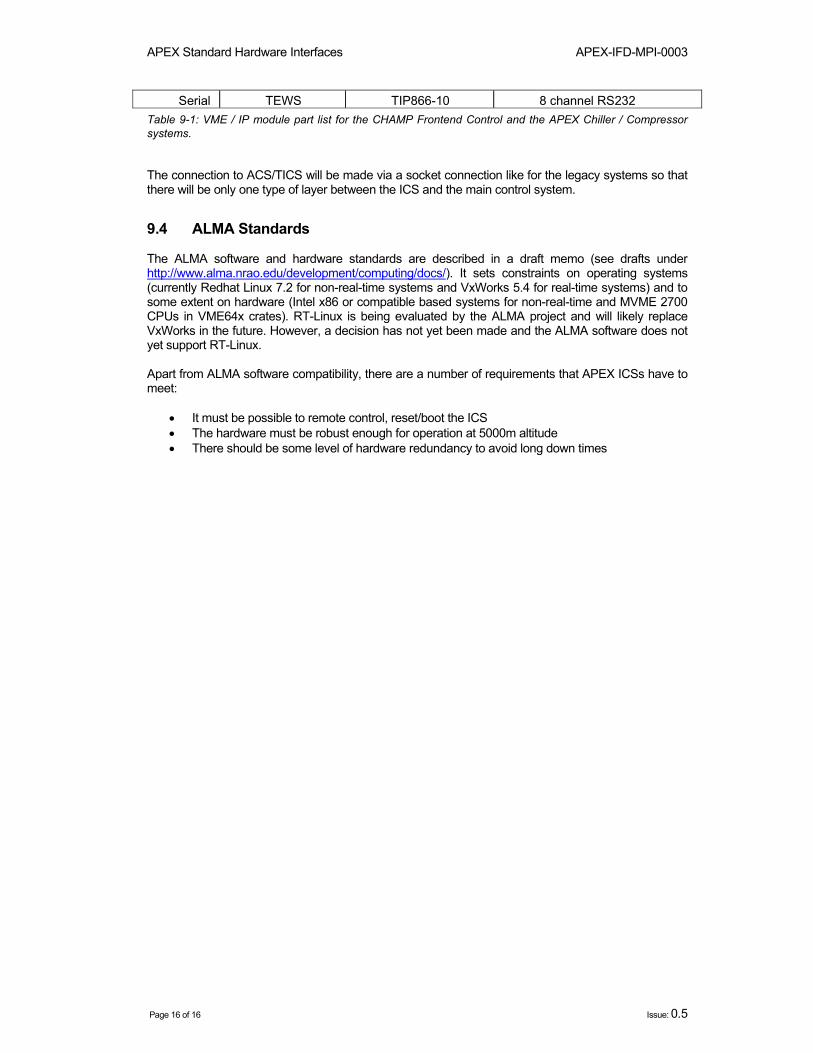
9.3 New Systems New APEX ICSs should be as close to ALMA standards as possible to ensure software compatibility and avoid extra layers that are difficult to maintain and add more possibilities for failures. It was agreed that the standard APEX ICSs will be an embedded VME Linux system using IP modules for digital I/O, ADC & DAC conversions, etc. The IP modules shall be software driver compatible with the ones used in the existing MPIfR systems for the compressor / chiller monitor and CHAMP. A detailed parts list is shown in Table 9-1.
Device Manufacturer Type Description
Cage SBS SCC484TV09VC719" 4U card cage,9X3U VMEslots,
250W power supply,floppy,10GB HD,CD,
LCD touch screen
CPU SBS VC7 3U VME CPU,500MHz Celeron
256 MB RAM IP carrier SBS VIPC 310
3U IP-carrier for 2 IP-modules
TEWS TVME210 3U IP-carrier for 2 IP-modules
Digital Input TEWS TIP600-10 16 channel opto input Digital Output TEWS TIP700-10 16 channel 24V output A/DC TEWS TIP501-20 16 channel 16Bit A/DC PT100 SBS IP-RTD 12 channel PT100 input
APEX Standard Hardware Interfaces APEX-IFD-MPI-0003
Page 16 of 16 Issue: 0.5
Serial TEWS TIP866-10 8 channel RS232 Table 9-1: VME / IP module part list for the CHAMP Frontend Control and the APEX Chiller / Compressor systems.
The connection to ACS/TICS will be made via a socket connection like for the legacy systems so that there will be only one type of layer between the ICS and the main control system.
9.4 ALMA Standards The ALMA software and hardware standards are described in a draft memo (see drafts under http://www.alma.nrao.edu/development/computing/docs/). It sets constraints on operating systems (currently Redhat Linux 7.2 for non-real-time systems and VxWorks 5.4 for real-time systems) and to some extent on hardware (Intel x86 or compatible based systems for non-real-time and MVME 2700 CPUs in VME64x crates). RT-Linux is being evaluated by the ALMA project and will likely replace VxWorks in the future. However, a decision has not yet been made and the ALMA software does not yet support RT-Linux. Apart from ALMA software compatibility, there are a number of requirements that APEX ICSs have to meet:
• It must be possible to remote control, reset/boot the ICS • The hardware must be robust enough for operation at 5000m altitude • There should be some level of hardware redundancy to avoid long down times