Embed Size (px)
Citation preview
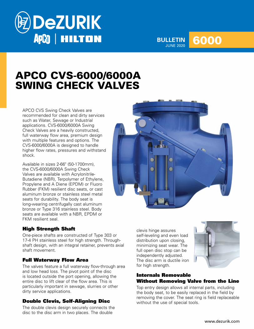
APCO CVS Swing Check Valves are recommended for clean and dirty services such as Water, Sewage or Industrial applications. CVS-6000/6000A Swing Check Valves are a heavily constructed, full waterway flow area, premium design with multiple features and options. The CVS-6000/6000A is designed to handle higher flow rates, pressures and withstand shock.
Available in sizes 2-66" (50-1700mm), the CVS-6000/6000A Swing Check Valves are available with Acrylonitrile-Butadiene (NBR), Terpolymer of Ethylene, Propylene and A Diene (EPDM) or Fluoro Rubber (FKM) resilient disc seats, or cast aluminum bronze or stainless steel metal seats for durability. The body seat is long-wearing centrifugally cast aluminum bronze or Type 316 stainless steel. Body seats are available with a NBR, EPDM or FKM resilient seal.
High Strength ShaftOne-piece shafts are constructed of Type 303 or 17-4 PH stainless steel for high strength. Through-shaft design, with an integral retainer, prevents axial shaft movement.
Full Waterway Flow AreaThe valves feature a full waterway flow-through area and low head loss. The pivot point of the disc is located outside the port opening, allowing the entire disc to lift clear of the flow area. This is particularly important in sewage, slurries or other dirty service applications.
Double Clevis, Self-Aligning DiscThe double clevis design securely connects the disc to the disc arm in two places. The double
clevis hinge assures self-leveling and even load distribution upon closing, minimizing seat wear. The full open disc stop can be independently adjusted. The disc arm is ductile iron for high strength.
Internals Removable Without Removing Valve from the LineTop entry design allows all internal parts, including the body seat, to be easily replaced in the field by removing the cover. The seat ring is field replaceable without the use of special tools.
BULLETIN
APCO CVS-6000/6000ASWING CHECK VALVES
JUNE 20206000
www.dezurik.com

Closure Control DevicesAir Cushion Side Mounted Cylinder (AC)For Free Open, Fast Close applications, the air cushioned check valve utilizes a totally enclosed
cushion cylinder externally mounted to the side of the main valve body. A heavy outside lever, positively clamped to an extra-large diameter pivot shaft, forces the disc to close immediately upon pump shut down and before reverse flow takes place. The weighted lever drives the piston into the cushion chamber, compressing the trapped air and creating a cushion during valve closure.
Principle of Operation1. Discharge velocity head from the pump
against the disc (10) opens the disc and raises the weighted lever (29) outside of the valve upward. At the same time, the piston inside the cushion cylinder (20) is pulled upward, drawing free air into the cushion cylinder through the one-way control check valve (30).
2. When reverse flow occurs against the backside of the disc (10), pressure forces the disc toward the shut-off position against the seat (5) at the same time forcing the cushion cylinder downward. Moving downward, the piston compresses the air in the cushion cylinder because the air cannot readily escape through the one-way control check valve. By restricting the air escape through the adjustable control check (30) air cushioned closing is accomplished.
3. Air cushioning is field adjustable by adjusting the flow control valve (30) for increased or decreased cushioning, or moving the weights on the pivot shaft for more or less rapid disc closure.
See pages 9 and 10 for lever and weight and lever and spring closure control devices.
2 © 2020 DeZURIK, Inc.
29
FLOW
10
5
For Sizes 2 - 6"(50 - 150 mm)
3020
29
FLOW
10
5
For Sizes 2 - 6"(50 - 150 mm)
3020
Fast Closing With Cushion At Shut-Off
30

3
Principle of Operation1. Discharge velocity head from the pump causes
the disc (10) to open and raises the outside weighted lever (29). Except for frictional resistance, the disc is free opening.
2. Three-stage closing is achieved by the oil dashpot/timing valve system which minimizes damaging water hammer. Each stage is independently adjustable.
a. The initial stage of closure is provided by the timing valve (45). The timing valve allows very fast closure of the disc from full open to any degree of closure. This feature greatly reduces the volume of backflow and flow reversal that occurs with on valves with only two stages of closure.
b. The second stage of closure is provided by the Flow Control Valve (30) that varies speed toward final closure.
c. The final stage of closure is provided by internal adjustment of the cylinder (20) that controls variable speed closure to shut-off.
d. Additional disc closing adjustments can be made by moving the weight on the pivot shaft.
Three Stage Closing Characteristics
The graph shows flow rate as a function of closing time and illustrates the superiority of the APCO three stage Oil Controlled Side Mounted Cylinder over two stage closure devices.
100% Open
Conventional Check Valvewithout Controls
Primary Control(Timing Valve)
Timing Valve ClosesAdjustable Start
of Secondary Control(Flow Control Valve)
Start of Third Stage Control(Internal Cushion Adjustment)For Faster
ClosureOverride SecondStage with the Timing Valve
t1 Min. t1 Max.
Flo
w
Time
Approximately5% Open
TimingValve
Configuration Sizes 2- 6"(50 - 150mm)
Timing Valve notsupplied on sizes2 - 4" (50 - 100mm)
Note: Oil reservoir must be mountedvertically regardless of valve installation position.Specify mounting position when ordering.
Timing Valve inClose Position
To RodEndSizes10 - 16"(250 - 400mm)
From cap end of cylinderon other side of valveSizes 10 - 16"(250 - 400mm)
Internal CushionedAdjustment Screw
Closure Control DevicesOil Controlled, Side Mounted Cylinder (OC)For Free Open, Slow Close applications, CVS-6000 Swing Check Valves are available with an Oil Controlled, Side Mounted Cylinder closure control device. The totally enclosed oil cylinder is protected from the elements. Three-stage closure on valves 6-20" (150-500mm) minimizes damaging water hammer.

Closure Control DevicesOil Controlled, Bottom Mounted Buffer (BMB)Bottom Mounted Buffers have been used successfully for decades to reduce slamming of the valve disc and resultant water hammer. For Free Open, Controlled Close applications, CVS-6000 Swing Check Valves sizes 8-66" (200-1700mm) are available with an Oil Controlled, Bottom Mounted Buffer closure control device.
Bottom Mounted Buffers are recommended for larger sized valves and for vertical upward flow installations. They are also recommended where instantaneous flow reversal caused by a hydro pneumatic surge tank or open line discharge is so fast that a free closing check valve cannot shut prior to reverse flow, and therefore slams.
4
Principle of Operation1. The unique buffer arrangement allows the valve
disc (10) to open fully without interference and to close freely for approximately 90% of its stroke.
2. After the disc is 90% closed, the disc comes in contact with the buffer rod (33). The oil hydraulic buffer makes contact with the disc and controls closure during the final 10% of the stroke.
3. The flow control valve (41) on the cylinder (39) easily adjusts closing time to suit flow conditions reducing slam, water hammer and pressure surges. The color-coded micrometer type control valve adjusts the final closure, and has a locking set screw that is used to secure the final setting.
29
10
Drain Opening
Note: Washing Action Automatically Cleans the Buffer Area
33
39
41

5
Closure Control DevicesConvertible Swing Check Valves (CLW & CLS)If hydraulic conditions exceed those anticipated, CVS Convertible Swing Check Valves can be converted in the field to closure control devices that reduce moderate or severe slam. For moderate slam, CVS-Convertible Lever & Spring Valves (CLS) or CVS-CLW Convertible Lever & Weight Valves (CLW) can be converted to an Air Cushion Side Mounted Cylinder. For severe slam, CVS-Convertible valves can be retrofitted in the field to Oil Controlled Side Mounted Cylinder or Bottom Mounted Buffer closure control devices.

6
Materials of ConstructionItem Description Material
A1 Body Ductile Iron, ASTM A536A2 Cover Ductile Iron, ASTM A536
A5 Body Seat
Aluminum Bronze, ASTM B148 with Acrylonitrile - Butadiene (NBR)316 Stainless Steel, ASTM A276 with Acrylonitrile - Butadiene (NBR)Aluminum Bronze, ASTM B148 with Terpolymer of Ethylene, Propylene and A Diene (EPDM)316 Stainless Steel, ASTM A276 with Terpolymer of Ethylene, Propylene and A Diene (EPDM)Aluminum Bronze, ASTM B148 with Fluoro Rubber (FKM)316 Stainless Steel, ASTM A276 with Fluoro Rubber (FKM)
A6 Disc Seat
Acrylonitrile-Butadiene (NBR)Terpolymer of Ethylene, Propylene and A Diene (EPDM)Fluoro Rubber (FKM)Aluminum Bronze, ASTM B148316 Stainless Steel, ASTM A276
A9 Disc Arm Ductile Iron, ASTM A536A10 Disc Ductile Iron, ASTM A536
A13 Pivot ShaftStainless Steel, Type 303, ASTM A58217-4 PH Stainless Steel, ASTM 564 Type 630
Valve SelectionShut-Off Capabilities
Applicable Standards
Pressure Ratings
Temperature Ratings
Seat Type Shut-OffAcrylonitrile-Butadiene (NBR)
Drip-TightTerpolymer of Ethylene, Propylene and A Diene (EPDM)Fluoro Rubber (FKM)
DeZURIK CVS-6000/6000A Swing Check Valves are designed and/or tested to meet the following standards:
AWWA C508AWWA C508-09 Swing-Check Valves for Waterworks Service 2-In Through 24-In (50-mm Through 600-mm) NPS
MSS SP-71 Testing Gray Iron Swing Check ValvesMSS SP-136 Testing Ductile Iron Swing Check ValvesASME B16.1 Gray Iron Pipe Flanges and Flanged FittingsASME B16.5 Conforms to Bolt Pattern and Drilling
Valve Size Pressure
2-66" (50-1700mm)
250 psi CWP (1720 kPa)
640 psi CWP (4140 kPa)
All Seats to 160° F (70° C)
Contact application engineering if the valve is required to operate above this temperature.
F1 =
F2 =
A02
A09
A05
A10
A06
A13
A01

7
Valve SelectionHead Loss Characteristics for Swing Check Valves
Flow in Gallons Per Minute
Hea
d L
oss
in F
eet
WeightsValve & Air Cushion Cylinder
Valve & Bottom Mounted Buffer
Valve Size
Weightlbs/kg
2"50mm
10648
2.5"65mm
13863
3"80mm
17579
4"100mm
238108
6"150mm
385175
8"200mm
475216
10"250mm
650295
12"300mm
1180536
14"350mm
1714778
16"400mm
22501021
18"450mm
27211235
20"500mm
32171460
24"600mm
41971905
30"750mm
66042997
36"900mm
118305368
42"1100mm
170507736
48"1200mm
2498011334
Valve Size
Weightlbs/kg
8"200mm
539245
10"250mm
795361
12"300mm
1150522
14"350mm
1803819
16"400mm
25001135
18"450mm
30221372
20"500mm
36001634
24"600mm
53202414
30"750mm
90004084
36"900mm
113405146
42"1100mm
172657834
48"1200mm
2500011344
54"1400mm
3464915721
60"1500mm
4430020100
66"1700mm
5394924478

8
Valve StyleGive valve style code as follows:CVS = Swing Check Valves
OrderingTo order, simply complete the valve order code from information shown. An ordering example is shown for your reference.
Body StyleGive body style code as follows:6000A = Series 6000A (2-14")6000 = Series 6000 (16-66")
End ConnectionGive end connection code as follows:F1 = Flanged ASME 125/150F2 = Flanged ASME 250/300
Body MaterialGive body material code as follows:DI = Ductile Iron
Trim CombinationDisc MaterialGive disc material code as follows:DI = Ductile Iron
Shaft MaterialGive shaft material code as follows:S11 = 303 Stainless Steel
(2-66" AC, LS or LW; 24-48" CLS or CLW; 8-48" BMB)S5 = 17-4PH Stainless Steel
(2-20" OC, CLS or CLW; 54-66" BMB, CLS or CLW)
Body Seat MaterialGive body seat material code as follows:For NBR, EPDM or FKM Disc Seat ALB = Aluminum Bronze (F1 only) S2 = 316 Stainless Steel (F1 only) For ALB or S2 Disc Seat ALBNB = Aluminum Bronze with NBR Seal S2NB = 316 Stainless Steel with NBR Seal ALBEP = Aluminum Bronze with EPDM Seal ALBFK = Aluminum Bronze with FKM SealS2EP = 316 Stainless Steel with EPDM Seal S2FK = 316 Stainless Steel with FKM Seal
Disc Seat MaterialGive disc seat material code as follows:NBR = Acrylonitrile-Butadiene EPDM = Terpolymer of Ethylene Propylene & A Diene FKM = Fluoro Rubber ALB = Aluminum Bronze S2 = 316 Stainless Steel
OptionsGive options code as follows: DTR = DeZURIK Standard Certified Production Hydrostatic
Shell & Seat Test Report VP = Vertical Flow Up Position Installation
(Not required with LS Closure Control Device) SB16 = 316 Stainless Steel Bolting
Closure Control DevicesGive closure control device code as follows: AC = Air Cushion Side Mounted Cylinder (Lever & Weight) BMB = Oil Controlled Bottom Mounted Buffer (8-66") OC = Oil Controlled Side Mounted Cylinder LS = Lever & Spring LW = Lever & Weight CLS = Convertible - Lever & Spring CLW = Convertible- Lever & Weight
AccessoriesGive accessory code as follows: SEL22 = (1) Limit Switch - DPDT AB H802T-DTP SEL30 = (1) Proximity Switch - SPDT GO 73-13526-B2 SEL32 = (1) Proximity Switch - DPDT GO 7G-23523-B2
Ordering Example:CVS,8,6000A,F1,DI,DI-S5-ALB-NBR*CLW,SEL22
Valve SizeGive valve size code as follows: 2 = 2" (50mm) 18 = 18" (450mm) 2.5 = 2.5" (65mm) 20 = 20" (500mm) 3 = 3" (80mm) 24 = 24" (600mm) 4 = 4" (100mm) 30 = 30" (750mm) 6 = 6" (150mm) 36 = 36" (900mm) 8 = 8" (200mm) 42 = 42" (1100mm) 10 = 10" (250mm) 48 = 48" (1200mm) 12 = 12" (300mm) 54 = 54" (1400mm) 14 = 14" (350mm) 60 = 60" (1500mm) 16 = 16" (400mm) 66 = 66" (1700mm)

9
DimensionsLever and Weight (LW)
Valve Size
F1 & F2 F1 F2A B C D F X Y G H G H
2"50mm
8.00203
6.00152
3.5089
13.25337
5.00127
9.50241
6.25159
6.00152
0.6316
6.50165
0.8822
2.5"65mm
8.50216
7.00178
4.00102
13.50343
5.25133
8.50216
5.75146
7.00178
0.6918
7.50191
1.0025
3"80mm
9.50241
7.00178
4.13105
13.75349
5.50140
8.50216
5.13130
7.50191
0.7519
8.25210
1.1329
4"100mm
11.50292
7.50191
5.00127
14.00356
6.00152
8.00203
5.00127
9.00229
0.9424
10.00254
1.2532
6"150mm
14.00356
10.00254
6.50165
17.00432
8.38213
14.25362
11.63295
11.00279
1.0025
12.50318
1.4437
8"200mm
19.50495
12.00305
10.25260
16.75425
8.50216
13.00330
9.25235
13.50343
1.1329
15.00381
1.6341
10"250mm
24.50622
14.25362
12.63321
21.00533
10.00254
13.50343
8.50216
16.00406
1.1930
17.50445
1.8848
12"300mm
27.50699
16.00406
14.00356
22.00559
11.50292
18.00457
11.25286
19.00483
1.2532
20.50521
2.0051
14"350mm
31.00787
19.63499
15.75400
26.00660
13.75349
20.00508
14.50368
21.00533
1.3835
23.00584
2.1354
16"400mm
36.00914
21.00533
19.75502
27.50699
14.50368
20.00508
14.00356
23.50597
1.4437
25.50648
2.2557
18"450mm
40.001016
24.00610
20.25514
29.00737
16.00406
24.50622
15.00381
25.00635
1.5640
28.00711
2.3860
20"500mm
40.001016
26.00660
21.50546
32.00813
17.50445
23.50597
15.00381
27.50699
1.6943
30.50775
2.5064
24"600mm
48.001219
30.00762
24.50622
33.50851
20.00508
28.00711
18.00457
32.00813
1.8848
36.00914
2.7570
30"750mm
56.001422
38.00965
27.75705
38.50978
24.00610
24.00610
15.50394
38.75984
2.1354
43.001092
3.0076
36"900mm
63.001600
40.381026
32.13816
41.501054
27.00686
21.00533
15.00381
46.001168
2.3860
50.001270
3.3886
42"1100mm
70.001778
50.631286
36.00914
49.001245
33.00838
41.001041
26.00660
53.001346
2.6367
57.001448
3.6994
48"1200mm
78.001981
50.631286
41.001041
60.001524
38.00965
47.501207
29.25743
59.501511
2.7570
65.001651
4.00102
54"1400mm
87.002210
62.131578
52.001321
65.001651
43.001092
50.501283
39.501003
66.251683
3.0076
Contact DeZURIK60"1500mm
97.002464
72.001829
58.001473
70.001778
46.001168
45.501156
35.50902
73.001854
3.1380
66"1700mm
108.002743
66.631692
64.001626
76.001930
50.501283
43.001092
33.50851
80.002032
3.4487
Note: 36" (900mm) & larger have two lever arms, one on each side. InchesMillimeters
V
W
C
B
FLOW
A
F
D
øG
H
SE
AT
SID
E
X
Y
VP - VERTICAL FLOW UPLEVER ARM SWING
FLOWSTANDARD
FLO
W
VP, STANDARD
FLO
W
VP, LEFT HANDFLOW
LEFT HAND
V
W
C
B
FLOW
A
F
D
øG
H
SE
AT
SID
E
X
Y
VP - VERTICAL FLOW UPLEVER ARM SWING
FLOWSTANDARD
FLO
W
VP, STANDARD
FLO
W
VP, LEFT HANDFLOW
LEFT HAND
V
W
C
B
FLOW
A
F
D
øG
H
SE
AT
SID
E
X
Y
VP - VERTICAL FLOW UPLEVER ARM SWING
FLOWSTANDARD
FLO
W
VP, STANDARD
FLO
W
VP, LEFT HANDFLOW
LEFT HAND

10
DimensionsLever and Spring (LS)
Valve Size
F1 & F2 F1 F2A B C D E F G H G H
2"50mm
8.00203
6.00152
3.5089
13.25337
6.50165
5.00127
6.00152
0.6316
6.50165
0.8822
2.5"65mm
8.50216
7.00178
4.00102
13.50343
10.50267
5.25133
7.00178
0.6918
7.50191
1.0025
3"80mm
9.50241
7.00178
4.13105
13.75349
10.00254
5.50140
7.50191
0.7519
8.25210
1.1329
4"100mm
11.50292
7.50191
5.00127
14.00356
5.38137
6.00152
9.00229
0.9424
10.00254
1.2532
6"150mm
14.00356
10.00254
6.50165
17.00432
8.00203
8.38213
11.00279
1.0025
12.50318
1.4437
8"200mm
19.50495
12.00305
10.25260
16.75425
8.00203
8.50216
13.50343
1.1329
15.00381
1.6341
10"250mm
24.50622
14.25362
12.63321
21.00533
10.50267
10.00254
16.00406
1.1930
17.50445
1.8848
12"300mm
27.50699
16.00406
14.00356
22.00559
10.75273
11.50292
19.00483
1.2532
20.50521
2.0051
14"350mm
31.00787
19.63499
15.75400
26.00660
10.25260
13.75349
21.00533
1.3835
23.00584
2.1354
16"400mm
36.00914
21.00533
19.75502
27.50699
13.00330
14.50368
23.50597
1.4437
25.50648
2.2557
18"450mm
40.001016
24.00610
20.25514
29.00737
11.50292
16.00406
25.00635
1.5640
28.00711
2.3860
20"500mm
40.001016
26.00660
21.50546
32.00813
10.00254
17.50445
27.50699
1.6943
30.50775
2.5064
24"600mm
48.001219
30.00762
24.50622
33.50851
7.38187
20.00508
32.00813
1.8848
36.00914
2.7570
30"750mm
56.001422
38.00965
27.75705
38.50978
_ 24.00610
38.75984
2.1354
43.001092
3.0076
36"900mm
63.001600
40.381026
32.13816
41.501054
7.25184
27.00686
46.001168
2.3860
50.001270
3.3886
42"1100mm
70.001778
50.631286
36.00914
49.001245
2.7570
33.00838
53.001346
2.6367
57.001448
3.6994
InchesMillimeters
FLOW
F
D
øG
H
SE
AT
SID
E
B
A
CE
FLOW
SE
AT
SID
E
LEFT HAND
FLOW
SE
AT
SID
E
STANDARD POSITION
CLOSURE CONTROL MOUNTING POSITIONS
(SHOWN ON THIS DRAWING)
FLOW
F
D
øG
H
SE
AT
SID
E
B
A
CE
FLOW
SE
AT
SID
E
LEFT HAND
FLOW
SE
AT
SID
E
STANDARD POSITION
CLOSURE CONTROL MOUNTING POSITIONS
(SHOWN ON THIS DRAWING)

11
DimensionsValve & Air Cushioned Side Mounted Cylinder (AC)
Valve Size
F1 & F2 F1 F2A B C D E F W X Y G H G H
2"50mm
8.00203
6.00152
3.5089
13.25337
10.75273
5.00127
9.00229
9.50241
6.25159
6.00152
0.6316
6.50165
0.8822
2.5"65mm
8.50216
7.00178
4.00102
13.50343
10.25260
5.25133
9.50241
8.50216
5.75146
7.00178
0.6918
7.50191
1.0025
3"80mm
9.50241
7.00178
4.13105
13.75349
10.13257
5.50140
9.50241
8.50216
5.13130
7.50191
0.7519
8.25210
1.1329
4"100mm
11.50292
7.50191
5.00127
14.00356
9.13232
6.00152
10.75273
8.00203
5.00127
9.00229
0.9424
10.00254
1.2532
6"150mm
14.00356
10.00254
6.50165
17.00432
10.38264
8.38213
16.50419
14.25362
11.63295
11.00279
1.0025
12.50318
1.4437
8"200mm
19.50495
12.00305
10.25260
16.75425
9.25235
8.50216
18.00457
13.00330
9.25235
13.50343
1.1329
15.00381
1.6341
10"250mm
24.50622
14.25362
12.63321
21.00533
8.63219
10.00254
20.50521
13.50343
8.50216
16.00406
1.1930
17.50445
1.8848
12"300mm
27.50699
16.00406
14.00356
22.00559
8.88226
11.50292
25.00635
18.00457
11.25286
19.00483
1.2532
20.50521
2.0051
14"350mm
31.00787
19.63499
15.75400
26.00660
11.00279
13.75349
29.00737
20.00508
14.50368
21.00533
1.3835
23.00584
2.1354
16"400mm
36.00914
21.00533
19.75502
27.50699
9.75248
14.50368
30.75781
20.00508
14.00356
23.50597
1.4437
25.50648
2.2557
18"450mm
40.001016
24.00610
20.25514
29.00737
8.25210
16.00406
35.00889
24.50622
15.00381
25.00635
1.5640
28.00711
2.3860
20"500mm
40.001016
26.00660
21.50546
32.00813
8.88226
17.50445
36.00914
23.50597
15.00381
27.50699
1.6943
30.50775
2.5064
24"600mm
48.001219
30.00762
24.50622
33.50851
6.00152
20.00508
43.751111
28.00711
18.00457
32.00813
1.8848
36.00914
2.7570
30"750mm
56.001422
38.00965
27.75705
38.50978
9.75248
24.00610
48.001219
24.00610
15.50394
38.75984
2.1354
43.001092
3.0076
36"900mm
63.001600
40.381026
32.13816
41.501054
5.00127
27.00686
51.001295
21.00533
15.00381
46.001168
2.3860
50.001270
3.3886
42"1100mm
70.001778
50.631286
36.00914
49.001245
1.0025
33.00838
65.001651
41.001041
26.00660
53.001346
2.6367
57.001448
3.6994
48"1200mm
78.001981
50.631286
41.001041
60.001524
6.00152
38.00965
75.001905
47.501207
29.25743
59.501511
2.7570
65.001651
4.00102
54"1400mm
87.002210
62.131578
52.001321
65.001651
16.00406
43.001092
84.002134
50.501283
39.501003
66.251683
3.0076
Contact DeZURIK60"1500mm
97.002464
72.001829
58.001473
70.001778
27.00686
46.001168
88.502248
45.501156
35.50902
73.001854
3.1380
66"1700mm
108.002743
66.631692
64.001626
76.001930
39.00991
50.501283
91.002311
43.001092
33.50851
80.002032
3.4487
InchesMillimeters
V
W
C
B
FLOW
A
øG
D
F
H
SE
AT
SID
E
E
X
Y
VP - VERTICAL FLOW UPLEVER ARM SWING
FLOWSTANDARD
FLOWLEFT HAND
FLO
W
VP, STANDARD
FLO
W
VP, LEFT HAND
V
W
C
B
FLOW
A
øG
D
F
H
SE
AT
SID
E
E
X
Y
VP - VERTICAL FLOW UPLEVER ARM SWING
FLOWSTANDARD
FLOWLEFT HAND
FLO
W
VP, STANDARD
FLO
W
VP, LEFT HAND
V
W
C
B
FLOW
A
øG
D
F
H
SE
AT
SID
E
E
X
Y
VP - VERTICAL FLOW UPLEVER ARM SWING
FLOWSTANDARD
FLOWLEFT HAND
FLO
W
VP, STANDARD
FLO
W
VP, LEFT HAND

DimensionsOil Controlled Side Mounted Cylinder
Valve Size
F1A B C D E F K W X Y G H
2"50mm
8.00203
6.00152
3.5089
13.25337
10.75273
5.00127
7.50191
9.00229
9.50241
6.25159
6.00152
0.6316
2.5"65mm
8.50216
7.00178
4.00102
13.50343
10.25260
5.25133
8.00203
9.50241
8.50216
5.75146
7.00178
0.6918
3"80mm
9.50241
7.00178
4.13105
13.75349
10.13257
5.50140
8.13207
9.50241
8.50216
5.13130
7.50191
0.7519
4"100mm
11.50292
7.50191
5.00127
14.00356
9.13232
6.00152
8.94227
10.75273
8.00203
5.00127
9.00229
0.9424
6"150mm
14.00356
10.00254
6.50165
17.00432
14.00356
8.38213
22.50572
16.50419
14.25362
11.63295
11.00279
1.0025
8"200mm
19.50495
12.00305
10.25260
16.75 425
12.50318
8.50216
24.00610
18.00457
13.00330
9.25235
13.50343
1.1329
10"250mm
24.50622
14.25362
12.63321
21.00533
8.63219
10.00254
28.00711
20.50521
13.50343
8.50216
16.00406
1.1930
12"300mm
27.50699
16.00406
14.00356
22.00559
8.88226
11.50292
29.50749
25.00635
18.00457
11.25286
19.00483
1.2532
14"350mm
31.00787
19.63499
15.75400
26.00660
11.00279
13.75349
33.00838
29.00737
20.00508
14.50368
21.00533
1.3835
16"400mm
36.00914
21.00533
19.75502
27.50699
9.75248
14.50368
35.50902
30.75781
20.00508
14.00356
23.50597
1.4437
18"450mm
40.001016
24.00610
20.25514
29.00737
8.25210
16.00406
37.50953
35.00889
24.50622
15.00381
25.00635
1.5640
20"500mm
40.001016
26.00660
21.50546
32.00813
8.88226
17.50445
39.00991
36.00914
23.50597
15.00381
27.50699
1.6943
Valve Size
F2A B C D E F K W X Y G H
2"50mm
8.00203
6.00152
3.5089
13.25337
10.75273
5.00127
7.50191
9.00229
9.50241
6.25159
6.50165
0.8822
2.5"65mm
8.50216
7.00178
4.00102
13.50343
10.25260
5.25133
8.00203
9.50241
8.50216
5.75146
7.50191
1.0025
3"80mm
9.50241
7.00178
4.13105
13.75349
10.13257
5.50140
8.13207
9.50241
8.50216
5.13130
8.25210
1.1329
4"100mm
11.50292
7.50191
5.00127
14.00356
9.13232
6.00152
8.94227
10.75273
8.00203
5.00127
10.00254
1.2532
6"150mm
14.00356
10.00254
6.50165
17.00432
14.00356
8.38213
22.50572
16.50419
14.25362
11.63295
12.50318
1.4437
8"200mm
19.50495
12.00305
10.25260
16.75425
12.50318
8.50216
24.00610
18.00457
13.00330
9.25235
15.00381
1.6341
10"250mm
24.50622
14.25362
14.13359
21.00533
12.00305
10.00254
28.00711
20.50521
13.50343
8.50216
17.50445
1.8848
12"300mm
27.50699
16.00406
15.50394
22.00559
12.00305
11.50292
29.50749
25.00635
18.00457
11.25286
20.50521
2.0051
14"350mm
31.00787
19.63499
17.25438
26.00660
14.25362
13.75349
33.00838
29.00737
20.00508
14.50368
23.00584
2.1354
16"400mm
36.00914
21.00533
21.25540
27.50699
15.50394
14.50368
35.50902
30.75781
20.00508
14.00356
25.50648
2.2557
18"450mm
40.001016
24.00610
21.75552
29.00737
16.75425
16.00406
44.001118
35.00889
24.50622
15.00381
28.00711
2.3860
20"500mm
40.001016
26.00660
23.00584
32.00813
19.25489
17.50445
46.001168
36.00914
23.50597
15.00381
30.50775
2.5064
InchesMillimeters
InchesMillimeters
12

13
W
V
E
K
L
B
C
D
F
A
øG
H
X
Y
VP - VERTICAL FLOW UPLEVER ARM SWING
DimensionsOil Controlled Side Mounted Cylinder
W
V
E
K
L
B
C
D
F
A
øG
H
X
Y
VP - VERTICAL FLOW UPLEVER ARM SWING
W
V
E
K
L
B
C
D
F
A
øG
H
X
Y
VP - VERTICAL FLOW UPLEVER ARM SWING
All Sizes
Size 2-8" (50-200mm)
Size 10-20" (250-500mm)
V
W
C
K
E
B

14
DimensionsValve & Oil Controlled Bottom Mounted Buffer (BMB)
Valve Size
F1 & F2 F1 F2A B C E F X Y D G H D G H
8"200mm
19.50495
12.00305
11.75298
25.00635
28.00711
13.00330
9.25235
1.1329
13.50343
11.75298
1.6341
15.00381
13.00330
10"250mm
24.50622
14.25362
14.13359
30.00762
33.50851
13.50343
8.50216
1.1930
16.00406
14.25362
1.8848
17.50445
15.25387
12"300mm
27.50699
16.00406
15.50394
31.50800
42.001067
18.00457
11.25286
1.2532
19.00483
17.00432
2.0051
20.50521
17.75451
14"350mm
31.00787
19.63499
17.25438
46.001168
48.001219
20.00508
14.50368
1.3835
21.00533
18.75476
2.1354
23.00584
20.25514
16"400mm
36.00914
21.00533
21.25540
46.001168
50.001270
20.00508
14.00356
1.4437
23.50597
21.25540
2.2557
25.50648
22.50572
18"450mm
40.001016
24.00610
21.75552
58.001473
56.001422
24.50622
15.00381
1.5640
25.00635
22.75578
2.3860
28.00711
24.75629
20"500mm
40.001016
26.00660
23.00584
64.001626
60.001524
23.50597
15.00381
1.6943
27.50699
25.00635
2.5064
30.50775
27.00686
24"600mm
48.001219
30.00762
26.00660
67.001702
65.001651
28.00711
18.00457
1.8848
32.00813
29.50749
2.7570
36.00914
32.00813
30"750mm
56.001422
38.00965
29.25743
77.001956
76.001930
24.00610
15.50394
2.1354
38.75984
36.00914
3.0076
43.001092
39.25997
36"900mm
63.001600
40.381026
33.79858
83.002108
86.002184
21.00533
15.00381
2.3860
46.001168
42.751086
3.3886
50.001270
46.001168
42"1100mm
70.001778
50.631286
37.91963
98.002489
95.002413
41.001041
26.00660
2.6367
53.001346
49.501257
3.6994
57.001448
52.751340
48"1200mm
78.001981
50.631286
42.161071
115.002921
108.002743
47.501207
29.25743
2.7570
59.501511
56.001422
4.00102
65.001651
60.751543
54"1400mm
87.002210
62.131578
53.161350
130.003302
120.003048
50.501283
39.501003
3.0076
66.251683
62.751594
Contact DeZURIK60"1500mm
97.002464
72.001829
59.251505
140.003556
130.003302
45.501156
35.50902
3.1380
73.001854
69.251759
66"1700mm
108.002743
66.631692
65.161655
152.003861
140.003556
43.001092
33.50851
3.4487
80.002032
76.001930
InchesMillimeters
VP - VERTICAL FLOW UPLEVER ARM SWING
V
W
F
C
B
A
E
D
øG
X
Y

15
DimensionsConvertible - Lever and Weight (CLW)Convertible - Lever and Spring (CLS)
Valve Size
F1 & F2 F1 F2A B C D E F W X Y G H G H
2"50mm
8.00203
6.00152
3.5089
13.25337
6.50165
5.00127
9.00229
9.50241
6.25159
6.00152
0.6316
6.50165
0.8822
2.5"65mm
8.50216
7.00178
4.00102
13.50343
10.50267
5.25133
9.50241
8.50216
5.75146
7.00178
0.6918
7.50191
1.0025
3"80mm
9.50241
7.00178
4.13105
13.75349
10.00254
5.50140
9.50241
8.50216
5.13130
7.50191
0.7519
8.25210
1.1329
4"100mm
11.50292
7.50191
5.00127
14.00356
5.38137
6.00152
10.75273
8.00203
5.00127
9.00229
0.9424
10.00254
1.2532
6"150mm
14.00356
10.00254
6.50165
17.00432
8.00203
8.38213
16.50419
14.25362
11.63295
11.00279
1.0025
12.50318
1.4437
8"200mm
19.50495
12.00305
10.25260
16.75425
8.00203
8.50216
18.00457
13.00330
9.25235
13.50343
1.1329
15.00381
1.6341
10"250mm
24.50622
14.25362
12.63321
21.00533
10.50267
10.00254
20.50521
13.50343
8.50216
16.00406
1.1930
17.50445
1.8848
12"300mm
27.50699
16.00406
14.00356
22.00559
10.75273
11.50292
25.00635
18.00457
11.25286
19.00483
1.2532
20.50521
2.0051
14"350mm
31.00787
19.63499
15.75400
26.00660
10.25260
13.75349
29.00737
20.00508
14.50368
21.00533
1.3835
23.00584
2.1354
16"400mm
36.00914
21.00533
19.75502
27.50699
13.00330
14.50368
30.75781
20.00508
14.00356
23.50597
1.4437
25.50648
2.2557
18"450mm
40.001016
24.00610
20.25514
29.00737
11.50292
16.00406
35.00889
24.50622
15.00381
25.00635
1.5640
28.00711
2.3860
20"500mm
40.001016
26.00660
21.50546
32.00813
10.00254
17.50445
36.00914
23.50597
15.00381
27.50699
1.6943
30.50775
2.5064
24"600mm
48.001219
30.00762
24.50622
33.50851
7.38187
20.00508
43.751111
28.00711
18.00457
32.00813
1.8848
36.00914
2.7570
30"750mm
56.001422
38.00965
27.75705
38.50978 — 24.00
61048.001219
24.00610
15.50394
38.75984
2.1354
43.001092
3.0076
36"900mm
63.001600
40.381026
32.13816
41.501054
7.25184
27.00686
51.001295
21.00533
15.00381
46.001168
2.3860
50.001270
3.3886
42"1100mm
70.001778
50.631286
36.00914
49.001245
2.7570
33.00838
65.001651
41.001041
26.00660
53.001346
2.6367
57.001448
3.6994
48"1200mm
78.001981
50.631286
41.001041
60.001524 — 38.00
96575.001905
47.501207
29.25743
59.501511
2.7570
65.001651
4.00102
54"1400mm
87.002210
62.131578
52.001321
65.001651 — 43.00
109284.002134
50.501283
39.501003
66.251683
3.0076
Contact DeZURIK60"1500mm
97.002464
72.001829
58.001473
70.001778 — 46.00
116888.502248
45.501156
35.50902
73.001854
3.1380
66"1700mm
108.002743
66.631692
64.001626
76.001930 — 50.50
128391.002311
43.001092
33.50851
80.002032
3.4487
InchesMillimeters
FLOW
F
D
øG
H
SE
AT
SID
E
SIZES 10"AND LARGER
X
A
Y
VP - VERTICAL FLOW UPLEVER ARM SWING
FLOWSTANDARD
FLO
W
VP, STANDARD
FLO
W
VP, LEFT HANDFLOW
LEFT HAND
V
W
C
B
FLOW
F
D
øG
H
SE
AT
SID
E
SIZES 10"AND LARGER
X
A
Y
VP - VERTICAL FLOW UPLEVER ARM SWING
FLOWSTANDARD
FLO
W
VP, STANDARD
FLO
W
VP, LEFT HANDFLOW
LEFT HAND
V
W
C
B
FLOW
F
D
øG
H
B
A
C
D
E
SIZES 10"AND LARGER
FLOW
SE
AT
SID
E
LEFT HANDFLOW
SE
AT
SID
E
STANDARD POSITION
CLOSURE CONTROL MOUNTING POSITIONS
(SHOWN ON THIS DRAWING)
FLOW
F
D
øG
H
B
A
C
D
E
SIZES 10"AND LARGER
FLOW
SE
AT
SID
E
LEFT HANDFLOW
SE
AT
SID
E
STANDARD POSITION
CLOSURE CONTROL MOUNTING POSITIONS
(SHOWN ON THIS DRAWING)
LEVER AND WEIGHT
LEVER AND SPRING

DeZURIK, Inc. reserves the right to incorporate our latest design and material changes without notice or obligation. Design features, materials of construction and dimensional data, as described in this bulletin, are provided for your information only
and should not be relied upon unless confirmed in writing by DeZURIK, Inc. Certified drawings are available upon request.
Printed in the U.S.A.
250 Riverside Ave. N. Sartell, Minnesota 56377 • Phone: 320-259-2000 • Fax: 320-259-2227
For information about our worldwide locations, approvals, certifications and local representative:Web Site: www.dezurik.com E-Mail: [email protected]
Sales and Service


![Abb 6000a Lv Mns Panel[1] Copy](https://img.dokumen.tips/doc/110x75/55cf99c5550346d0339f12e0/abb-6000a-lv-mns-panel1-copy.jpg)