Embed Size (px)
Citation preview

Solvent, fuel and many other VOC vapors are pervasively common in many workplace environments. Most have surprisingly low toxic exposure limits. While a wide range of techniques and equipment are available for measuring the concentrations of these contaminants in air, PID equipped instruments are generally the best choice for measurement of VOCs at exposure limit concentrations. Whatever type of instrument is used to measure these hazards, it is essential that the equipment is used properly, and the results are correctly interpreted.
• WhatareVOCs?
Volatile organic chemicals (VOCs) are organic chemicals or mixtures characterized by their tendency to evaporate easily at room temperature. Familiar VOCs include solvents like MEK and acetone, paint thinner and nail polish remover, as well as the vapors associated with fuels such as gasoline, diesel, heating oil, kerosene and jet fuel. The category also includes many specific toxic chemicals such as benzene, butadiene, hexane, toluene, xylene, and many others. Increased awareness of the toxicity of these common contaminants has led to lowered exposure limits, and increased requirements for direct measurement of these substances at their exposure limit concentrations. Photoionization detector equipped instruments are increasingly being used as the detection technique of choice for these hazards.
AP1021:
UsingphotoionizationdetectorstomeasuretoxicVOCs
AP1021_10_10_13
Tel: (800) 959-0329 or (734) 769-0573 Fax: (734) 769-1888E-mail: [email protected] Website: www.gfg-inc.com
VOCs present multiple potential threats in the workplace environment. Many VOC vapors are heavier than air, and can act to displace the atmosphere in an enclosed environment or confined space. Oxygen deficiency is a leading cause of injury and death in confined space accidents. The literature contains many examples of fatal accidents caused by oxygen deficiencies due to displacement by VOC vapors.
Most VOC vapors are flammable at low concentrations. For instance, the lower explosion limit (LEL) concentrations for toluene and hexane are only 1.1% (11,000 ppm). By comparison, it takes 5% volume methane (50,000 ppm) to reach an ignitable concentration in air. Because most VOCs produce flammable vapors, in the past, the tendency has been to measure them by means of combustible gas measuring instruments. Combustible gas reading instruments usually provide readings in percent LEL increments, where 100% LEL indicates a fully ignitable concentration of gas. Combustible gas instrument alarms are usually set to go off if the concentration exceeds 10% LEL. Unfortunately, most VOC vapors are also toxic, with Permissible Exposure Limit (PEL) values much lower than the 10% LEL hazardous condition
For most VOCs, long before you reach aconcentrationsufficienttoregisteronacombustiblegas indicator, you will have easily exceeded thetoxic exposure limits for the contaminant. PIDequipped instruments are generally the bestchoiceformeasurementofVOCsatexposurelimitconcentrations.
Figure1:Photoionizationdetector(PID)equippedinstrumentsareincreasinglyviewedasthebestchoiceformeasurementofVOCsatexposurelimitconcentrations.
threshold for combustible gas. The toxic exposure limits are exceeded long before the LEL alarm concentration is reached.
An important obligation for every employer is to ensure that workers are not harmed by exposure to toxic materials or conditions that may be present in the workplace environment. Exposure limits like the OSHA PEL, NIOSH REL and ACGIH® TLV® provide limits, which if exceeded, may lead to immediate or long term harm. These guidelines and standards set the limits above which conditions are deemed to be hazardous. Workers should be out of the area before rather than after the concentration of toxic gas exceeds the hazardous condition threshold. Which exposure limit is applicable and enforceable depends on where you are, what you are doing, and who is responsible for enforcing your workplace safety requirements.
Airborne toxic substances typically are classified on the basis of their ability to produce physiological effects on exposed workers. Toxic substances tend to produce symptoms in two time frames: acute and chronic. Hydrogen sulfide (H2S) is a good example of an acutely toxic substance that is immediately lethal at relatively low concentrations. Exposure to 1,000 ppm produces rapid paralysis of the respiratory system, cardiac arrest, and death within minutes. Carbon monoxide (CO) also acts rapidly at high concentrations (1,000 ppm) although not as rapidly as hydrogen sulfide.
While some VOCs are acutely toxic at low concentrations, most are chronically toxic, with symptoms that may not become fully manifest for years. Exposure can be via skin or eye contact with liquid or aerosol droplets, or via inhalation of VOC vapors. Inhalation can cause respiratory tract irritation (acute or chronic) as well as effects on the nervous system such as dizziness, headaches and other long-term neurological symptoms. Long-term neurological symptoms can include diminished cognition, memory, reaction time, and hand-eye and foot-eye coordination, as well as balance and gait disturbances. Exposure can also lead to mood disorders, with depression, irritability, and fatigue being common symptoms. Peripheral neurotoxicity effects include tremors, and diminished fine and gross motor movements. VOCs have also been implicated in kidney damage and immunological problems, including increased cancer rates. Benzene, a notoriously toxic VOC found in gasoline, diesel, jet fuel and other chemical products, has been linked to chemically induced leukemia, aplastic anemia and multiple myeloma (a cancer of the lymphatic system). There is good reason that the occupational exposure limits for VOC vapors are as low as they are. Unfortunately, because of the chronic or long-term nature of the physiological effects of exposure, the tendency in the past has been to overlook their potential presence in the workplace environment at PEL concentrations.
AP1021Page2
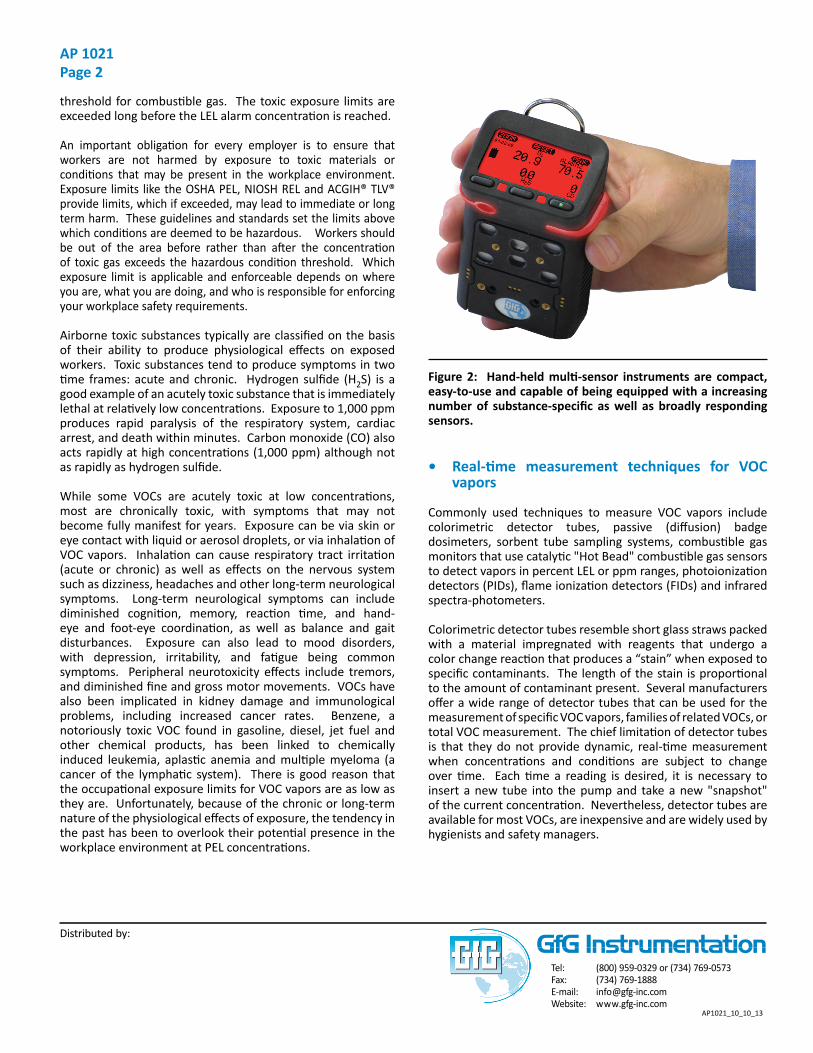
Figure2: Hand-heldmulti-sensor instruments are compact,easy-to-useandcapableofbeingequippedwithaincreasingnumberof substance-specific aswell as broadly respondingsensors.
• Real-time measurement techniques for VOCvapors
Commonly used techniques to measure VOC vapors include colorimetric detector tubes, passive (diffusion) badge dosimeters, sorbent tube sampling systems, combustible gas monitors that use catalytic "Hot Bead" combustible gas sensors to detect vapors in percent LEL or ppm ranges, photoionization detectors (PIDs), flame ionization detectors (FIDs) and infrared spectra-photometers.
Colorimetric detector tubes resemble short glass straws packed with a material impregnated with reagents that undergo a color change reaction that produces a “stain” when exposed to specific contaminants. The length of the stain is proportional to the amount of contaminant present. Several manufacturers offer a wide range of detector tubes that can be used for the measurement of specific VOC vapors, families of related VOCs, or total VOC measurement. The chief limitation of detector tubes is that they do not provide dynamic, real-time measurement when concentrations and conditions are subject to change over time. Each time a reading is desired, it is necessary to insert a new tube into the pump and take a new "snapshot" of the current concentration. Nevertheless, detector tubes are available for most VOCs, are inexpensive and are widely used by hygienists and safety managers.
Distributed by:
Tel: (800) 959-0329 or (734) 769-0573 Fax: (734) 769-1888E-mail: [email protected] Website: www.gfg-inc.com
AP1021_10_10_13

AP1021Page3
Distributed by:
Tel: (800) 959-0329 or (734) 769-0573 Fax: (734) 769-1888E-mail: [email protected] Website: www.gfg-inc.com
Badge-type passive dosimeters and sorbent tube sampling systems depend on absorption or adsorption of VOC contaminants into or onto a sorbent medium. Once the sampling period has been completed, the badge or tube is sent to a laboratory for analysis. Badge-type dosimeters are small devices designed to clip onto the shirt collar and depend on diffusion to load the VOC onto the absorbing media. Sorbent tubes depend on a precision low flow sampling pump used to pull a calibrated volume of air through the tube over a specific interval of time. The chief limitation with both techniques is that readings are not obtainable in real-time. However, results are both accurate and substance specific. Not only is it possible to quantify the overall amount of VOC present, it is possible to identify and determine the concentration of specific contaminants.
Flame ionization detectors use a hydrogen flame as the source of ionization energy used to remove an electron from neutrally charged VOC molecules. The electrically charged fragments (ions) are collected, and produce a flow of electrical current proportional to the concentration of contaminant. FIDs are able to detect nearly all organic compounds. Hydrocarbons generally have FID response factors that are equal to the number of carbon atoms in their molecule. Oxygenates and other species that contain heteroatoms tend to have lower response factors.
FID is especially useful for determining the total volatile organic chemical (TVOC) concentration since the response is highly proportional to the total number of carbon atoms in the VOC molecules present in the monitored atmosphere. The chief limitations are the limited resolution, expense of the instruments, and the high pressure (16 MPa or 2300 lb/in2) cylinder of hydrogen required by the instrument. Refilling and storage represent significant issues for most users.
Both PIDs and FIDs are types of ionization detectors. Ionization detectors provide broad-range readings for VOCs. The reading provided represents the aggregate signal from all of the detectable VOCs present in the monitored environment. Unless an additional separation technique is used (such as a chromatographic separation column) ionization detectors are not able to provide substance specific readings.
Infrared spectra-photometers provide readings based on the absorbance of infrared light by VOC molecules. Specific molecules absorb infrared radiation at precise wavelengths. When infrared radiation passes through a sensing chamber containing a specific contaminant, only those wavelengths that match one of the vibration modes of the molecule are absorbed. The rest of the light is transmitted through the chamber without hindrance. The presence of a particular chemical group within
AP1021_10_10_13
a molecule thus gives rise to characteristic absorption bands. Since most chemical compounds absorb at a number of different frequencies, IR absorbance can provide a "fingerprint" for use in identification of unknown contaminants. The chief limitations are the expense of the instruments, the training required, and the interpretation of results.
• Multi-sensorportablegasdetectors
Portable multi-sensor gas detectors can be equipped with a number of different types of sensors. The type of sensor used is a function of the specific substance or class of contaminant being measured. Many toxic contaminants can be measured by means of substance-specific electrochemical sensors. Direct reading sensors are available for hydrogen sulfide, carbon monoxide, chlorine, sulfur dioxide, ammonia, phosphine, hydrogen, hydrogen cyanide, nitrogen dioxide, nitric oxide, chlorine dioxide, ethylene dioxide, ozone and others. Although some of these sensors are cross sensitive to other substances,
Figure3:TheGfGG460mainboardassemblyequippedwithstandardLEL,O2,dual-channelCOSHsensor forCOandH2S,NDIR sensor for CO2 and high range combustible gas, andminiaturizedPIDforVOCmeasurement.
MiniaturizedPIDsensor
CatalyticLELsensor
Infrared(NDIR)dualchannelCO2andcombustiblegassensor
COSHsensor O2
sensor

AP1021Page4
there is very little ambiguity when it comes to interpreting readings. When you are interested in hydrogen sulfide, you use a hydrogen sulfide sensor. When you are interested in phosphine, you use a phosphine sensor. In many cases, however, a substance-specific sensor may not be available.
• HowdoLELsensorsdetectgas?
The most widely used technique for the measurement of combustible gas continues to be use of a hot-bead pellistor type combustible gas sensor that provides readings in percent LEL (Lower Explosive Limit) increments. Pellistor sensors detect gas by oxidizing the gas on an active bead located within the sensor. Oxidization of the gas causes heating of the active bead. The heating is proportional to the amount of gas present in the atmosphere being monitored, and is used as the basis for the instrument reading. Most combustible gas reading instruments display readings in % LEL increments, with a full range of 0 – 100% LEL. Typically these sensors are used to provide a hazardous condition threshold alarm set to 5% or 10% of the LEL concentration of the gases or vapors being measured. Readings are usually displayed in increments of ±1.0% LEL. Hot-bead pellistor combustible gas sensors are unable to differentiate between different combustible gases.
Many manufacturers include a user selectable library of correction factors (or “CFs”) for the combustible gas sensor in the instrument design. In this case, the user simply selects “methane” or “propane” or any other correction factor in the library, and the instrument automatically recalculates readings according to the selected relative response. Changing the CF ONLY changes the scale used to calculate the displayed readings. Selecting the “propane” CF does not prevent the sensor from responding to methane. It just reinterprets the readings as if they were entirely due to propane.
Hot-bead pellistor sensors that display readings in ±1.0% LEL increments are excellent for gases and vapors that are primarily or only of interest from the standpoint of their flammability. Some combustible gases, such as methane and propane, do not have a permissible exposure limit. For these gases using a sensor that expresses readings in percent LEL increments is an excellent approach. But most other combustible gases and vapors fall into a different category. Although VOC vapors may be measurable by means of a hot-bead sensor, they usually have a PEL that requires taking action at a much lower concentration.
Hexane provides a good example. The lower explosive limit concentration for n-hexane is 1.1%. Below 1.1% volume the concentration of n-hexane vapor to air is too low to form an ignitable mixture. Assuming the combustible sensor alarm is set at 10% LEL, with a properly calibrated combustible gas reading instrument, it would take a concentration of 10% of
Figure4:Tobedetectable,combustiblegasmoleculesmustbesmallenoughtopass readily throughtheflamearrestorandpenetratetheactivebead(pellistor)inastandardLELsensor.
Figure5:Settingthealarmat10%LELsignificantlyexceedsthetoxicexposurelimitsforn-hexane.
Distributed by:
Tel: (800) 959-0329 or (734) 769-0573 Fax: (734) 769-1888E-mail: [email protected] Website: www.gfg-inc.com
AP1021_10_10_13

AP1021Page5
1.1% = 0.11% volume n-hexane to trigger an alarm. Since 1% volume = 10,000 parts-per-million (ppm), every 1% LEL increment for hexane is equivalent to 110 ppm. It would therefore take a concentration of 1,100 ppm hexane to trigger an alarm set to the standard 10% LEL hazardous condition threshold. However, according to both the NIOSH REL and the ACGIH® TLV® the toxic exposure limit for n-hexane is only 50 ppm (8-hour TWA). Even if instruments are set to alarm at 5% LEL, it still would still require a concentration of 550 ppm to trigger the alarm.
Table 1 lists ten common VOCs, their LEL concentration, flashpoint temperature, and their exposure limits per the OSHA PEL, NIOSH REL and ACGIH® TLV®. The table also identifies those contaminants (highlighted in red) with toxic exposure limits lower than 5% LEL.
Using a combustible gas monitor to measure VOCs presents a number of other potential problems as well. To begin with, most combustible sensors have poor sensitivity to the large molecules found in fuels, solvents and other VOCs with flashpoint temperatures higher than 38°C (100°F). But even when the span sensitivity of a properly calibrated instrument has been increased sufficiently to make up for this inherent loss of sensitivity, an instrument that provides readings incremented in 1.0% LEL steps cannot resolve changes in concentration smaller than ± 1.0% of the LEL concentration of the substance being measured. Because percent LEL detectors are poor indicators for the presence of many VOCs, lack of a reading is not necessarily proof of the absence of hazard.
Reliance on hot-bead type LEL sensors for measurement of VOC vapors means in many cases that the PEL, REL or TLV® is exceeded long before the concentration of vapor is sufficient to
trigger the combustible hazardous condition threshold alarm. When toxic VOCs are potentially present it is necessary to use additional or different detection techniques that are better suited for direct measurement of VOCs at ppm toxic exposure limit concentrations. Photoionization detectors are becoming increasingly popular for this application.
It should be noted that other combustible gases and vapors may be present at the same time as toxic VOCs. Although catalytic-bead sensors may have limitations with concern to the measurement of toxic VOCs at exposure limit concentrations, they are by far the most widely used and dependable method for measuring methane and other combustible gases and vapors with smaller, lighter molecules.
It goes beyond the scope of this article to argue how long it might be permissible to remain at 5% or 10% LEL without actually exceeding the 8-hr. TWA or STEL. What is most striking about the list is how few VOCs have 8-hour TWA exposure limits higher than 5% LEL. None of the VOCs on the list have exposure limits higher than 10% LEL.
• Howphotoionizationdetectorsdetectgas
Photoionization detectors use high-energy ultraviolet light from a lamp housed within the detector as a source of energy used to remove an electron from neutrally charged VOC molecules, producing a flow of electrical current proportional to the concentration of contaminant.
The amount of energy needed to remove an electron from the target molecule is called the ionization energy (IE) for that substance. The larger the molecule, or the more double or triple bonds the molecule contains, the lower the IE. Thus, in
Table1:ExposureLimitsandPhysicalConstantsforTenCommonVOCsContaminant LELConcentration
(Vol%)FlashpointTemp(°F) OSHAPEL NIOSHREL TLV 5%LELexpressed
inPPM
Acetone 2.50% -4°F 1,000PPMTWA 250PPMTWA 500PPMTWA 1250PPM
Diesel(No.2)vapor 0.60% 125°F NoneListed NoneListed 15PPM 300PPM
Gasolinevapor 1.30% -50°F NoneListed NoneListed 300PPMTWA 650PPM
n-Hexane 1.10% -7°F 500PPMTWA 50PPMTWA 50PPMTWA 550PPM
Isopropylalcohol 2.00% 53°F 400PPMTWA 400PPMTWA 200PPMTWA 1000PPM
Kerosene/JetFuelvapor
0.70% 100–162°F NoneListed 100mg/m3TWA(approx.14.4PPM)
200mg/m3TWA(approx.29PPM)
350PPM
MEK 1.40% 16°F 200PPMTWA 200PPMTWA 200PPMTWA 700PPM
Styrene 0.90% 88°F 100PPMTWA 50PPMTWA 20PPMTWA 450PPM
Toluene 1.1 40°F 200PPMTWA 100PPMTWA 20PPMTWA 550PPM
Turpentine 0.8 95°F 100PPMTWA 100PPMTWA 20PPMTWA 400PPM
Distributed by:
Tel: (800) 959-0329 or (734) 769-0573 Fax: (734) 769-1888E-mail: [email protected] Website: www.gfg-inc.com
AP1021_10_10_13

Figure3:PIDdetectionsequence.
AP1021Page6
general, the larger the molecule, the easier it is to detect! This is exactly the opposite of the performance characteristics of the catalytic hot-bead type combustible sensor.
Photoionization detectors are extremely sensitive. Depending on the design, PIDs can provide readings from the low parts-per-billion range up to 10,000 ppm or higher. Photoionization detectors may be equipped with a number of different types of lamps that produce photons of various energy ranges. The energy range of the photons produced by the lamp is expressed in “electron volts” or “eV” units of measurement. The most common types of PID lamps produce photons in the 9.8 eV, 10.6 eV or 11.7 eV energy range. The energy required to detect hydrogen, methane and ethane exceeds the energy of the ultraviolet light produced by any available PID lamp.
By far, the most commonly used PID lamp is one that produces photons in the 10.6 eV energy range. 10.6 eV lamps generally have much longer service lives, and frequently last two to three years in normal operation. At the same time, 10.6 eV lamps have an energy output sufficient to detect a wide range of VOCs. As a consequence, 10.6 eV lamps tend to be the most widely used.
• WhatarethedifferencesbetweenPIDandLELsensors?
PID and lower explosive limit (LEL) sensors are based on entirely different detection techniques. Most LEL range sensors detect gas by catalytically oxidizing the gas on a pellistor-bead located within the sensor. Oxidization of the gas causes heating of the active pellistor-bead. The heating is proportional to the amount of gas present in the atmosphere being monitored, and is used as the basis for the instrument reading. Pellistor sensors are excellent for the detection of methane, propane, pentane and other small hydrocarbon molecules. However, catalytic-bead sensors, at least when operated in the percent LEL range, are not readily able to detect “heavy” or long-chain hydrocarbons or the vapors from high flashpoint temperature liquids such as turpentine, diesel fuel or jet fuel. Consult the Operator’s Manual, or contact the manufacturer directly to verify the capabilities of the instrument design when using a catalytic-bead LEL sensor to monitor for the presence of these types of contaminants.
Catalytic hot-bead combustible sensors and photoionization detectors represent complementary, not competing detection techniques. Catalytic hot-bead sensors are excellent for the measurement of methane, propane, and other common combustible gases that are not detectable by means of a PID. On the other hand, PIDs can detect large VOC and hydrocarbon molecules that are effectively undetectable by hot-bead sensors, even when they are operable in ppm measurement ranges.
Distributed by:
Tel: (800) 959-0329 or (734) 769-0573 Fax: (734) 769-1888E-mail: [email protected] Website: www.gfg-inc.com
AP1021_10_10_13

AP1021Page7
The best approach to VOC measurement in many cases is to use a multi-sensor instrument capable of measuring all the atmospheric hazards that may be potentially present. Having a single instrument equipped with multiple sensors means no condition is accidentally overlooked.
• Whatarebroad-rangesensors?
Broad-range sensors provide an overall reading for a general class or group of chemically related contaminants. Both pellistor-bead LEL and PID are broad-range sensors. They cannot distinguish between the different contaminants they are able to detect. The reading provided represents the aggregate signal from all of the detectable molecules present in the monitored environment. Both PIDs and pellistor bead sensors are broad-range sensors. Unless an additional separation technique is used (such as a filter tube or separation column) broad-range detectors are not able to provide substance-specific readings.
• Usingcorrectionfactors
Most PID equipped instruments also include a built-in library of correction factors. Just like with catalytic LEL sensors, changing the PID correction factor (CF) or choosing a chemical from the on-board library does not make the instrument readings specific for that substance. Choosing the “hexane” correction factor does not make the PID a substance-specific detector for hexane. The PID will continue to respond to other detectable VOCs (such as benzene or toluene) which may be simultaneously present. Using the hexane CF simply tells the instrument to display the readings calculated as hexane measurement units.
PIDs are usually calibrated using isobutylene. Thus, the most commonly used measurement scale for most PIDs is isobutylene. It is very important to understand that no matter how comprehensive the list of correction factors, choosing the CF for any particular chemical does not make the readings exclusive or substance-specific for that contaminant.
Also, if the specific nature of the VOC or mixture of VOCs is not known, PID readings are not truly quantified. Unless you are able to determine the precise nature of the VOCs being measured, readings should be thought of as “isobutylene units”, or “PID units”, or units of whatever measurement scale has been selected from the instrument’s library of correction factors.
Correction factors may also change as the lamp ages and the signal strength declines. As well, the signal strength of the PID may also be affected by the temperature and humidity in which the instrument is used. The best approach is to use correction factors cautiously, and to take action at a deliberately conservative concentration when using corrected readings.
Figure7:PIDcomponentsshowingdetectorbodyandplug-inelectrodestack(whichsitsflushagainstthesurfaceofthelamp).
Figure8:PIDcomponentsshowingdetectorbodyandlamp.
Figure 6: Miniaturized photoionization detectors are thesamesizeandhavesimilarpowerrequirementstotraditionalpellistortypeLELsensors.
Distributed by:
Tel: (800) 959-0329 or (734) 769-0573 Fax: (734) 769-1888E-mail: [email protected] Website: www.gfg-inc.com
AP1021_10_10_13

AP1021Page8
to experimentally determine a CF for use with this fuel. You don’t have to go after the individual molecular types that may be present as a minor fraction of the diesel (such as benzene, toluene, xylenes, etc.) to provide a quantified reading. If you have a CF for the mixture you can use this to quantify the readings for the entire range of molecules present.
HowdoImakedecisionswhenIdon'tknowwhichVOCisproducingthePIDreading?
Dealing with single-component VOC contaminants or mixtures is easy. Once you know which contaminant you are dealing with, simply assign the correct CF, and set the alarms to the appropriate take action thresholds for that VOC. Dealing with varying mixtures can be a little more challenging. In this case the secret is to identify which chemical is the “controlling” compound.
Every mixture of VOCs has a compound that is the most toxic and / or hardest to detect, and thus “controls” the alarm set-
Table2:RepresentativeCorrectionFactorsforSeveralBrandsofPhotoionizationDetectors*
RAE BW IonScience GfG IonizationEnergy(eV)
Acetaldehyde 5.5 4.6 4.9 N/A 10.21
Acetone 1.1 0.9 0.7 1.2 9.69
Ammonia 9.7 10.6 8.5 9.4 10.2
Benzene 0.5 0.6 0.5 0.5 9.25
Butadiene 1 0.9 0.9 0.7 9.07
DieselFuel 0.8 0.9 0.8 0.9 N/A
Ethanol 12 13.2 8.7 10 10.48
Ethylene 10 11 8 10.1 10.52
Gasoline 0.9 0.7 1.1 1.1 N/A
n-Hexane 4.3 4 3.3 4.5 10.18
JetFuel(JP-8) 0.6 0.5 0.7 0.5 N/A
Kerosene N/A** 1.1 0.8 N/A N/A
Methyl-ethyl-ketone(MEK) 0.9 0.8 0.8 0.9 9.53
Naphtha(iso-octane) 1.2 1.2 1.1 1.3 9.82
Styrene 0.4 0.5 0.5 0.4 8.47
Toluene 0.5 0.5 0.5 0.5 8.82
Turpentine 0.4 0.5 0.5 0.5 N/A
Vinylchloride 2 2.2 2.2 1.8 10
Xylene 0.4 0.5 0.4 0.5 8.5*The values listed are from technical notes and manuals previously published by the identified manufacturers. Never use the correction factors provided by one manufacturer for a different brand of instrument. Manufacturers routinely update their technical support documentation. Consult the manufacturer directly to obtain the latest version.
** “N/A” does not necessarily indicate the PID is unable to detect this substance. “N/A” only indicates that a CF for the vapor was not included in the technical support documentation. Instrument users should consult the manufacturer directly for guidance as to the detectability of a particular chemical.
Photoionization detectors are easily able to provide readings at or below the PEL or TLV® for all of the VOCs listed in Table1, including diesel. Table2 lists representative PID correction factors from the manuals of several different manufacturers.
• FrequentlyaskedPIDquestionsandconcerns
CanIstilluseaPIDevenwhenIneedsubstance-specificreadings?
PIDs provide a single reading for the total detectable volatile organic contaminants (TVOC) present. In point of fact, many of the most common VOCs do not consist of a single type of molecule. They are comprised of a mixture of, in some cases, a very large number of individual molecular species. For instance, the size distribution of molecules in diesel fuel ranges from molecules with nine carbons (or smaller), to molecules with twenty-three carbons (or larger). However, the ratios of the various molecules present are fairly similar from one batch of diesel to the next. That allows PID manufacturers
Distributed by:
Tel: (800) 959-0329 or (734) 769-0573 Fax: (734) 769-1888E-mail: [email protected] Website: www.gfg-inc.com
AP1021_10_10_13

AP1021Page9point that should be used for the entire mixture. Once the controlling compound has been identified, it is possible to determine a hazardous condition threshold alarm that will ensure that the PEL for any contaminant potentially present is never exceeded.
The first step is to calculate (or look up) the exposure limits in isobutylene units for the VOCs of interest. Remember to leave the PID scale (correction factor) set to isobutylene units when using this measurement technique. The exposure limit in isobutylene units (ELiso) is calculated by dividing the exposure limit (PEL) for the VOC by the correction factor (CFiso) for the substance. The OSHA PEL for turpentine is 100 ppm. Thus, if the CF for turpentine is 0.45, the ELiso = 100 ppm divided by 0.45 = 222 ppm. Many PID manufacturers include a table of ELiso values either in the owner’s manual or in a separate applications note.
Consider a situation where you have three VOCs of interest: ethanol, toluene and acetone. Let’s say the owner’s manual of the PID you intend to use includes a table with the following set of values:
ChemicalName
10.6eVCFiso ELChemical(USAPEL)
ELiso
Ethanol 13.3 1000 75.2
Turpentine 0.45 100 222
Acetone 1.2 500 416.7
Correction factors higher than 1.0 indicate that the PID is less sensitive to the substance than to the isobutylene used to calibrate the PID. Correction factors of less than 1.0 indicate that the PID is more sensitive to the chemical than to the isobutylene used to calibrate the detector.
Although turpentine has the lowest PEL, it is also the most easily detected substance of the three. Acetone is close to isobutylene in terms of detectability, with a PEL that is intermediate between those of the other two chemicals. Although ethanol has the highest exposure limit, it is also the least detectable of the three chemicals, thus, ethanol is the controlling compound when the Exposure Limits are expressed in equivalent “Isobutylene Units”. Setting the PID to go into alarm at 75 ppm isobutylene units ensures that no matter which of the three chemicals, or combination of chemicals, is actually present, the PEL will never be exceeded.
CanIuseanothermanufacturer’scorrectionfactorsformyownPIDinstrument?
Photoionization detectors may be equipped with a number of different types of lamps that produce photons of various
energy ranges. The energy range of the photons produced by the lamp is expressed in “electron volts” or “eV” units of measurement. The most common types of PID lamps produce photons in the 9.8 eV, 10.6 eV or 11.7 eV energy range. By far, the most commonly used PID lamp is one that produces photons in the 10.6 eV energy range.
Generally speaking, if a VOC is detectable by one manufacturer’s PID when equipped with a 10.6 eV lamp, the same substance will be detectable by any other manufacturer’s PID when equipped with a similar lamp. The correction factors may be quite different, however between the two instrument designs!
The reason is primarily due to the specific energy ranges of the photons produced by the lamp. Not all of the photons produced by a 10.6 eV lamp are actually 10.6 eV photons. The majority of the photons produced are actually in the 10.03 eV energy range. Only about 20% to 25% of the photons produced (depending on the design of the lamp) are in the 10.6 eV energy range. All of the photons produced by the lamp are capable of ionizing and detecting VOCs with ionization energies less than 10.0 eV. But only the higher energy photons are able to ionize and detect VOCs with ionization energies between 10.1 and 10.6 eV. Thus, correction factors may differ widely between manufacturer designs. PID users should never use the correction factors from one instrument for another manufacturer’s design.
Ifa10.6eVlampisgood,whywouldn'tan11.7eVlampbeanevenbetterchoice?
The energy of the photons produced by the UV lamp determines whether a specific chemical is detectable. The energy must be higher than the ionization energy of the contaminant in order for detection to occur. Lamps are available in a number of output energies including 9.5, 9.8, 10.0, 10.2, 10.6, 11.7 and 11.8 eV (depending on manufacturer). Many manufacturers allow for the use of several lamps in the same detector. The lower the energy of the UV light produced by the lamp, the lower the number of chemicals the PID will be able to detect. The higher the energy of the light produced by the lamp, the wider the range of detectable contaminants.
While it is true that an 11.7 eV lamp is capable of detecting more substances than a 10.6 eV lamp, the actual number of photons produced by the lamp, that is, the intensity of the lamp, is usually lower than that of the 10.6 eV lamp. So, generally speaking, an equivalent concentration of a substance that is detectable by either a 10.6 eV or an 11.7 eV lamp will produce a weaker raw electrical signal with the 11.7 eV lamp. Although the instrument electronics automatically takes this into account when an 11.7 eV lamp is installed, the fact remains that higher energy lamps tend to produce both
Distributed by:
Tel: (800) 959-0329 or (734) 769-0573 Fax: (734) 769-1888E-mail: [email protected] Website: www.gfg-inc.com
AP1021_10_10_13

AP1021Page10
a weaker ionization current and have an increased tendency towards drift. Thus, the 10.6 eV lamp usually produces better resolution and accuracy for readings of substances that can be detected with the lower energy lamp.
Higher energy lamps are also subject to more physical limitations. In general, the higher the lamp energy, the shorter will be the service life. In some cases high energy 11.7 eV lamps may only last one or two months in normal operation.
10.6 eV lamps generally have much longer service lives, and frequently last two to three years in normal operation. At the same time, 10.6eV lamps have an energy output sufficient to detect a wide range of VOCs. As a consequence, 10.6 eV lamps tend to be the most widely used.
CanIusemyPIDinplaceofatraditionalLELsensor?
Catalytic hot-bead combustible sensors and photoionization detectors represent complementary, not competing detection techniques. PIDs are not able to detect methane and hydrogen, two of the most common combustible gases encountered in industry. On the other hand, catalytic pellistor-bead sensors are excellent for the measurement of methane, propane, and other common combustible gases. And of course, PIDs can detect large VOC and hydrocarbon molecules that are effectively undetectable by hot-bead sensors, even when they are operable in PPM measurement ranges. The optimal strategy for measurement of combustible range concentrations of combustible gases and VOCs is to include both types of sensors in the same instrument.
CanaPIDbeusedtomeasureVOCsinthepresenceofmethane?
Methane molecules are capable of absorbing UV light. Because the UV photons are absorbed without the methane being ionized, the presence of high concentrations of methane can “quench” or reduce the ability of the PID to detect other vapors that are present at the same time. The tendency of methane to reduce the PID signal is very design dependent. One of the most important determinants is the distance of the sensing electrode in the PID from the surface of the window of the PID lamp. The further that the photons have to travel before ionizing the VOC target molecules, the greater effect that quenching gases such as methane will have on readings. The following table lists the effects of various concentrations of methane on the readings from a set of several GfG Instrumentation PIDs when the instruments were exposed to 100 ppm hexane.
%Vol.CH4 %LELCH4 Readingwhenexposedto50ppmhexaneinthepresenceofCH4
2.5% 50%LEL 26ppm
1.0% 20%LEL 45ppm
0.5% 10%LEL 48ppm
0.25% 4%LEL 49ppm
At 50% LEL (= 2.5% volume methane) readings were reduced by 50%. At 5% LEL (= 0.25% volume methane), readings were reduced by less than 2.0%. In this case a true concentration of 50 ppm hexane would be expected to show a reading of about 49 ppm.
As discussed above, instruments used for the detection of combustible gases such as methane should include an LEL sensor directly able to measure these gases. As long as the concentration of methane does not exceed 5% LEL (the combustible hazardous condition threshold alarm set-point for many industrial applications) the effects of methane quenching on the PID are trivial.
CanPIDsbeusedinhighambienthumidity?
Humidity and moisture can have a serious effect on PID performance. Once again however, the effects of humidity are very design dependent. Water molecules, like methane molecules, can absorb UV light without becoming ionized, and thus quench the PID signal similarly to methane. Once again, the tendency of water vapor to reduce the PID signal is very design dependent. Again, one of the most important determinants is the distance of the sensing electrode in the PID from the surface of the window of the PID lamp. Most PID designs deliberately position the sensing electrode as close as possible to the surface of the lamp window to reduce the effects of humidity. PID manufacturers also provide tables of correction factors that can be used to correct readings for humidity at various temperature and RH conditions. Alternatively, it easy to correct for these ambient conditions simply by calibrating the PID in the temperature and humidity conditions in which the instrument is actually used.
A second related issue is the condensation of water on the inside of the PID detector. When dirt or dust particles accumulate on the surface of the lamp, electrodes or PID sensing chamber, they provide points of nucleation around which water vapor can coalesce to produce misting similar to the fog that develops on a bathroom mirror. In two electrode PID designs this can lead to surface electrical current flows directly between the sensing and counter electrodes. This “moisture leakage” can result in a rising signal or positive drift in the PID readings. The potential for moisture leakage can be reduced by cleaning the lamp and / or detector.
Distributed by:
Tel: (800) 959-0329 or (734) 769-0573 Fax: (734) 769-1888E-mail: [email protected] Website: www.gfg-inc.com
AP1021_10_10_13

PIDs that have been designed to minimize the size of the gap between the face of the window and the sensing electrode generally have the lowest response to humidity. In the case of designs that include a fence electrode, condensation of water vapor does not tend to produce a positive drift, or interfere with the ability of the PID to obtain proper readings.
DoesaPIDhavetoincludeabuilt-inpumporfantoobtainreadings?
Whether or not the PID requires a pump or fan to move the sample through the sensing chamber is a function of the manufacturer’s design. Many PID designs include a built-in pump or fan. Other designs allow the addition of a motorized pump to obtain samples from areas that are remote from the detector. The easiest way to determine whether or not a pump is required is to evaluate the instrument before purchase. Most manufacturers and distributors are more than willing to make instruments available to potential customers for field trialing.
CanaPIDbeusedinplaceofcommonsubstance-specificelectrochemicalsensors(likethoseusedtomeasureH2S)?
PIDs are able to detect a wide variety of VOC and other toxic chemicals including hydrogen sulfide, ammonia, phosphine, chlorine and others. However, PIDs are broad-range sensors that cannot discriminate between a specific toxic contaminant and other detectable chemicals that may be simultaneously present. When a highly toxic specific contaminant like H2S is potentially present, it is better to use a substance-specific sensor that responds only to that particular hazard.
Fortunately, PID equipped multi-sensor instruments are available that include six or more channels of detection, allowing users the latitude of choosing exactly the combination of sensors they need to keep their workers safe.
• Conclusion
In the past, photoionization detectors have tended to be bulky, temperamental and expensive. This has changed dramatically over the last few years. Today, compact, multi-sensor designs that include LEL, O2, and electrochemical toxic sensors, as well as a miniaturized photoionization detector, have allowed this very useful detection technique to be included in many confined space, HAZMAT, and environmental monitoring programs.
AP1021Page11
Distributed by:
Tel: (800) 959-0329 or (734) 769-0573 Fax: (734) 769-1888E-mail: [email protected] Website: www.gfg-inc.com
Distributed by:
Tel: (800) 959-0329 or (734) 769-0573 Fax: (734) 769-1888E-mail: [email protected] Website: www.gfg-inc.com
AP1021_10_10_13