Embed Size (px)
Citation preview

AO-A107 303 DEFENSE COW.NICATIONS ENGINEERINS CENTER RESTON VA FIG 1?/2.1ADA1733 APPLICATION OF 0DISITAI. TROPOSCATnER To THE DCSjU)SEP ac .J L OSTERI4OLZ. V J1 CYBROVSKI
VNCLASSIFIED OCEC-TR-10-80 o
Eh EEEhim

11111L 12
IIIJIL25 1.
MICROCOPY RESOLUTION TEST CHARTNATIONAL HUR~AIJU 01l ANE[A~tl, 1961 A,

SLEL ' -
TR 10- 80
TECHNICAL REPORT NO. 10-80
IAPPLICATION OF DIGITAL
TROPOSCATTER TO THE DCS
4
SEPTEMBER 1980ELECTE
5Wo 17 1981
APPROVED FOR PUBLIC RELEASE; DISTRIBUTION UNLIMITED
--- -1 17 009

UNCLASSIFIED Seutwer~~ 1980SECURITY CLASS-FIrATION OF THIS -453E ("- .1 OE jco-d)
I... GOVT... ACC_____ _ NO 3)9 CATO NUMBER)
/ i J.L.lost-erholzN C~RC
V ~~~W. J./Cybrowski,~______S.i PERFORMING "OANIZ ATION NAME AND ADDRESS 10 PROGRAW LEMENT. PROJECT, TASK
Defense Communications Engineering Center AP-01A~ ORK UNIT NUMBERS
Transmission Engineering Division, R200 N/A1860 Wiehie Ave., Reston, VA 22090
I I. CONTROLLING OFFICE NAME AND ADDRESS 12. REPORT OAT E
Same as #9
4. -MONITORING AGENCY NAME & ADDRESS()/ dIll,.,,) tf- Contlolind Office) IS. SECURITY CLAfrSWSJ. I.~t
Uncl assi fiedN/A ISo. DECLASSIFICATION/OOWNORADING
SC.HEDUL E N/A16- DISTRIBUTION STATEMENT (of th4. R.p.o)
A. Approved for public release; distribution unlimited
17. DISTRIBUTION4 STATEMENT (of th btac en1.,,tered In Block 20. If different from Retport)
N/A
IS. SUPPLEMENTARY NOTES I
Review relevance 5 years from submission date.
19. KEY WORDS (Coninue* on reverse aide if necessary and identify by block nuib.,)
Digital Troposcatter Requirements Troposcatter Technology ReviewDigital Troposcatter Transmissionul ichannelro isional Design Criteria
20. ABSTRACT (Continuem ro * 1 ol Of necessary mnd Identify by block nuo~ben)A DCS digital troposcatter requirements and technology baseline is presentedfor use by system planners and managers. The current troposcatter linkretained through the 1990's. Current developments in digital troposcattertechnology are reviewed, including the results of key tests.Prvsoadesign criteria which were developed for digital troposcatter links based onthis testing are presented. This report supersedes draft DCEC TR 17-76,
a, "Integration of Digital Troposcatter into the Defense Coemmunications System"
D ,m,1473 EDITION OF I NOVOS6 IS OBSOLETE UNCLASSIFIEDSECURITY CLASSIFICATION OF THIS PAGE (When Dot. EnZ
1-4 -

EC RITY CLASSIFICATION OF THIS PAGE(Wh.. Dots E..trd)
nd draft DCEC TR 9-79, "Application of Digital Troposcatter to the DCS'.
UNCLASSIFIEDSECURITY CLASSIFICATION OF TIS PACE(UY..f Pae. Ent.,d)

Ar.ession For
NTIS GRA&IDTIC TAB []Unannounced IJustification
By__________
*Distribution/ _
Availability Codes TECHNICAL REPORT NO. 10-80Avail and/or
[Dist Speial APPLICATION OF DIGITAL
*TROPOSCATTER TO THE DCS
SEPTEMBER 1980
Prepared by:
J. L. OsterholzW. J. Cybrowski
Technical Content App ed: Approved for Release:
FAEDEIC A m#-ROBERT E. LYONSLt Col, USAF Deputy DirectorChief, TransmissionEngineering Division
FOREWORD
The Defense Communications Engineering Center Technical Reports (TR's)are published to inform interested members of the defense community regardingtechnical activities of the Center, completed and in progress. They areintended to stimulate thinking, encourage information exchange, and provideguidance for related planning and research. They are not an integral partof the DoD PPBS cycle and should not be interpreted as a source of programguidance.
Comments or technical inquiries concerning this document are welcome, andshould be directed to:
DirectorDefense Communications Engineering Center 41860 Wiehle AvenueReston, Virginia 22090 ELECTE
NOV 17 1981i; ii D D7
-V

EXECUTIVE SUMMARY
This Technical Report presents DCS digital troposcatterrequirements and a technology baseline. It also provides systemplanners and managers with the results of key system decisions toassist in the detailed system planning of DCS digital transmissionprojects involving troposcatter.
Troposcatter has historically provided a major long-haul,multichannel transmission capability for the Defense CommunicationsSystem (DCS). This capability was established via extensive tandemsystems such as 486L, which stretches from Spain to Turkey; the NorthAtlantic Radio System (NARS), which connects the North Americancontinent and Europe via Canada, Greenland, Iceland and the UnitedKingdom (UK); the Japan Troposcatter System (JTS) which providesmultichannel connectivity between Okinawa and Mainland Japan; and theEuropean Tropo-Army (ETA),which provides multichannel connectivitybetween the Federal Republic of Germany (FRG) and the UK. Thesubsequent development of a global military communications satellitesystem, the Defense Satellite Communications System (DSCS), and theemergence of many foreign national communications systems (e.g., inJapan and FRG) has provided the stimulus to reassess the need fortroposcatter transmission in a modern, digital DCS, particularly inview of the escalating costs of maintaining equipment based onessentially 20-year-old technology.
It is on this basis that the current troposcatter linkinventory of the DCS is reviewed. Using economic and operationguidelines, a subset of this inventory is identified representingthose links which are likely to be retained and digitized in theDCS through the 1990's. As expected, a significant reduction innumerical requirements is forecast, with approximately 30 percent(about 40 links) of the current inventory making up thecandidate digital troposcatter link requirements model.Deactivation of those links not included in this subset isgenerally predicated on the availability of other connectivityor a potential reduction in subscriber requirements (to permitcost effective use of lease service), and will not be specificallyaddressed.
With this in mind, subsystem design requirements areidentified for a DCS digital troposcatter transmission capabilitywhich can meet the overall DCS design requirements ofperformance, availability, and digital system compatibility. Forexample, the capability to modify certain DCS inventory analogtroposcatter radios to permit interface with a digitaltroposcatter modem is defined, as well as subsystem performancerequirements for new troposcatter RF facilities. Much of thecurrent DCS troposcatter equipment is approaching 20 yearsof age and is becomming increasingly difficult to supportlogistically, and therefore replacement RF components must beidentified to satisfy those link requirements where digitizationof the in-place troposcatter radio equipment is impractical.
iii4
-,

Given a selective but significant digital troposcatterrequirement and the desirability of developing alternative digitaltransmission technologies, two RDT&E programs were conducted by theMILDEPS, one by the Army and one by the Air Force, to addressdevelopment of a megabit digital troposcatter transmissioncapability. As a result of these efforts, digital troposcattertransmission has been successfully demonstrated over a number ofactual links at nominal data rates up to 12.6 Mb/s. One of thesemodem techniques, the Distortion Adaptive Receiver (DAR), developedby the Air Force, is being used in the TRI-TAC AN/TRC-170( )(V)tactical digital troposcatter radio terminal full scale developmentprogram. Another modem technique, the Adaptive Decision FeedbackEqualizer (ADFE), was developed under an Army DCS RDT&E program. TheADFE technique implementation resulted in the MD-918/GRC modem whichthe Army and Air Force plan to use for upgrading the first two DCSDigital European Backbone (DEB) links. The RDT&E phase for these twomodem techniques has been completed. Combined U.S. and NATO systemlevel comparative testing of the two modem techniques over links ofthe NATO ACE High transmission system have been accomplished. Sincethe specialized nature of these technologies has precluded theirwidespread visibility, this report compares the current developmentsby means of a review of digital troposcatter technology, a comparisonof key test results, and an examination of implementationpracticalities.
Based on the performance data obtained during theaforementioned testing, provisional design criteria have beendeveloped for DCS digital troposcatter links and are presentedherein. This report provides the analysis and derivation ofthese criteria which have previously been stated in DCEC TR 12-76[1]. The criteria described utilize new system performanceparameters, such as fade outage rate and duration, which are moreintimately related to the performance of current and anticipatedDCS subscriber services than any used heretofore. These criteriaare intended to be used in all DCS digital troposcatter linkimplementations. Links operating in the diffraction and mixedpropogation modes are also required to meet the performance critieria.
Following this analysis, a number of transmission systemengineering issues are examined to address certain key systemengineering decisions such as required spectrum availability and theextent to which the AN/TRC-170 can be used in the DCS, as well as theviability of using transmission components (e.g., time divisionmultiplexers) which have not been specifically optimized fortroposcatter use. Some of these areas remain open because the fullimpact of a particular issue has not been defined (e.g., the lack ofavailable spectrum in the l and 2 GHz frequency bands).Nevertheless, the current baseline digital troposcatter capability isseen to adequately support near term implementations such as theDigital European Backbone (DEB) transmission upgrade, see Figure 1.
iv
4

,~i. _
Finally, appendicies are included in this report which addressareas of special interest; i.e., the derivation of a digitaltroposcatter channel performance model, digital troposcatter linkacceptance and quality assurance (QA) methods, and a digitaltroposcatter modem performance specification. The QA appendixcomplements a similar section in DCEC TR 12-76 which deals withdigital Line-of-Sight (LOS) link acceptance and quality assurance.The modem performance specification represents the technical basisfor the planned DCS digital troposcatter modem procurement.
vI
( I.
, |l I I I I II
i i i i - i 1

TABLE OF CONTENTS
EXECUTIVE SUMMARY
I. THE ROLE OF TROPOSCATTER IN THE DCS 1
1. Network Philosophy 1
2. Troposcatter Upgrades - Near Term 2
a. Digital European Backbone (DEB) 2
b. Digital Terrestrial Extension - Turkey and Greece 3
3. Troposcatter Upgrades - Future 3
II. DCS DIGITAL TROPOSCATTER TRANSMISSION CONFIGURATIONS 10
Ill. DIGITAL TROPOSCATTER TRANSMISSION TECHNOLOGY 22
1. The Digital Troposcatter Channel 22
2. Implicit Diversity 33
3. Digital Troposcatter Transmission Technology 38
a. Comparison of the DAR and MD-918/GRC Modems 38
b. Other Modem Techniques 57
c. Electronic Countermeasure (ECM) Susceptibility 57
d. Summary 57
IV. DIGITAL TROPOSCATTER LINK ENGINEERING 60
1. Background 60
2. Link Design Criteria 65
3. Error-Free Block Probability 77
4. Service Probability 78
V. TRANSMISSION SYSTEM ENGINEERING CONSIDERATIONS 82
1. Link Capacity 83
2. Bandwidth Availability 83
3. Conversion of DCS Troposcatter Links to 84Higher Frequencies
vi
' __ __ __ __ _
-I- - - -- - - -- _ _ __ _ _

TABLE OF CONTENTS (CONT'D)
Page
4. Troposcatter Facility Design/O&M Reduction 89
5. Digital Equipment Compatibility 89
a. Loss of synchronization at the Digital Troposcatter 91Modem Level
b. Loss of synchronism in the level 2 TDM 95
c. Loss of synchronization at the PCM/TDM level 97
REFERENCES 101
APPENDIXES
A Quality Assurance Test Methods for DCS Digital Troposcatter Links A-l
B Performance Specification for the DCS Digital Troposcatter B-lModem MD-( ) (Draft)
.v
~vii
IL
I- .

LIST OF ILLUSTRATIONS
Figure Title Page
1. DEB IV Connectivity 4
2. Digital Terrestrial Extension - Turkey 5
3. Candidate DCS Digital Tropo Links in Europe 6
4. Candidate DCS Digital Tropo links in the Pacific 9
5. DCS Digital Troposcatter Configurations 1!
6a. Digital Tropo System Data/Timing Flow (Transmit) 12
6b. Digital Tropo System Data/Timing Flow (Receive) 13
7. Tropo Diversity Configurations 15
8. Typical Digital Tropo Facility Receiver Configuration 18
9. DCS Digital Tropo Facility 20
10. Forward Scatter Channel Scattering Function 23
11. Relationship of RMS Channel Dispersion to Correlation 25Bandwidth
12. Cumulative Distribution of Normalized Multipath 26Dispersion
13. Delay Power as a Function of Effective Earth Radius 28
14. European K Values 29
15. Troposcatter Fading Behavior (Typical Non-Diversity) 30
16. Atmospheric Ducting 32 I
17. Examples of RSL and Dispersion Measured During 34 fAircraft Passes
18. Frequency Correlation Function for a Typical Medium 36Distance Path
19. Mean Bit Error Probability and Implicit Diversity 39for DPSK
20. Linear Transversal Equalizer 41
viii
1.

LIST OF ILLUSTRATIONS (CONT'D)
Page
21. Decision Feedback Equalizer with Diversity 42Reception
22. MDTS Over-the-Air Performance Youngstown - Verona 46(168 mi), 6.3 Mb/s
23. MDTS Over-the-Air Performance Youngstown - Verona 47(168 mi), 12.6 Mb/s
24. MDTS Media Simulator Performance, 250 Miles, 480.6* Antenna BW, K=4/3, 6.3 Mb/s
25. DAR Waveforms (Ideal) 49
26. Functional Block Diagram of DAR-IV QPSK Receiver 50
27. DAR Over-the-Air performance Youngstown-Verona 52
(168 miles), 3.5 Mb/s
28. DAR Media Simulator Performance, 250 mile, 7 Mb/s 53
29. Digital Troposcatter Modem Performance Summary 55
30. Viterbi Algorithm with Diversity Reception 58
31. Idle Channel Noise vs Bit Error Probability for PCM 61
32. Troposcatter RF Link Outage Probability 69
33. Troposcatter Link Outage Rate 70
34. Troposcatter Link Outage Duration 71
35. Distriblition of Troposcatter Hop Outage Duration 72
36. Standard Deviation of Path Loss vs Effective 75(Angular) Distance
37. Long Term Distribution of a Typical DCS 76Troposcatter Hop
38. Troposcatter Link Block Error Probability 79
39. Incremental System Gain as a Function of 80
Service Probability
40. Required System Gain vs Frequency 85
41. Aperture-to-Medium Coupling Loss vs Scatter 87Angle/Antenna Beamwidth
ix
.k _ _ _
-W -L- _ _ -_ _

LIST OF ILLUSTRATIONS (CONT'D)
Page
42. Relationship of Path Distance and Frequency 8B
to Loss
1. 43. Markov State Representation of Synchronization 92
Loss Hierarchy
44. Simulated Short Term Channel Dispersion 93
45. Mean Time Between Loss of BCI - Digital Tropo 94
Modem
46. Mean Time Between Loss of BCI - Level 2 TDM 960
47. Mean Time Between Loss of BCI - PCM/TDM 100
x
L

LIST OF TABLES
Table Title Page
I. Generic Troposcatter Transmission Applications 6
II. Projected Future DCS Digital Troposcatter 7Applications
Ill. DCS Candidate Digital Tropo Requirement Matrix 8
IV. DCS Digital Troposcatter Spectral Efficiency Objectives 14
V. DCS Troposcatter Frequency Bands 16
VI. Major DCS Inventory Troposcatter Radio Equipments and 17
Configurations Suitable for Digitization
VII. Typical Analog Troposcatter Radio Modifications 17
VIII. Tropo Facility Performance Monitor/Equipment Status 21Requirements
IX. Comparison of MD-918/GRC and DAR Modem Demonstrated 59Performance
X. Major DCS Subscriber Types 60
XI. DCS PCM Voice Performance Characteristics 65
XlI. Candidate Link Requirements (Hypothetical Link) 73
XIII. DCS Link Design Requirements for a Typical Digital 74Troposcatter Link
XIV. Digital Troposcatter System Engineering Issues and 82Component Impacts
xi

I. THE ROLE OF TROPOSCATTER IN THE DCS
1. NETWORK PHILOSOPHY
Troposcatter transmission as employed in the DefenseCommunications System (DCS) has historically providedmultichannel communications to subscriber communities which,because of geographic or political constraints, are relativelyisolated from the rest of the network. As an example,troposcatter transmission currently provides backboneconnectivity in some regions of the DCS in order to joinmultichannel subscribers which are dispersed beyond line-of-sight(e.g., the 486L and JTS Systems). Troposcatter transmissionexperienced its greatest expansion between 1958 and 1968 in thisapplication. Unfortunately, requirements for rapid connectivitycoupled with a lack of realistic implementation guidelinesresulted in the notoriously erratic performance of manytroposcatter links installed during this time [2]. Sparserefurbishment programs compounded the substandard performance ofthese links and further reduced the effectiveness of troposcatteras a backbone communications medium. This undoubtedlycontributed to the present categorization of troposcatter as anextraordinary maintenance burden and the belief that troposcatteris intrinsically undesirable for cost effective, multichannelcommunications.
The development of operational military satellitecommunications (MILSATCOM) systems, such as the Defense SatelliteCommunications System (DSCS), provides an alternativemultichannel transmission capability beyond microwaveline-of-sight (LOS), and thus reliance on the troposcatter mediumis expected to be reduced, particularly in long tandemapplications. However, it is generally agreed that the mosteffective transmission network will continue to employ a mixedmedia inventory (i.e., satellite, LOS, troposcatter, leasedservice) where political, economic, survivability, and performance(i.e., system availability) considerations determine theselection of one transmission medium over another to satisfy aparticular requirement. The current development of digitaltransmission technology provides a convenient point to readdressthe area of transmission media utilization in the DCS and todefine the specific role, if any, for troposcatter.
Generally, multichannel communications over very long distancesare most effectively provided by communications satellites. However,a number of situations require government-owned connectivity whereterrestrial communications, in general (troposcatter in particular),can be considered as preferred alternatives over MILSATCOM. Thesesituations (identified in Table I and based on the planned MILSATCOMcapability for the 1980-1985 time frame), do not generally representviable satellite applications. It can be shown that terrestrialtransmission (particularly troposcatter) is generally preferred over
L

the present DSCS system for moderate cross section multichannelconnectivity requirements spanning 500 miles (800 km) or less.Further, it is clear that exclusive use of communications satellitetrunking will not result in an optimally survivable network due tothe dependence on one or, at best, a small number of nodal equipments(e.g., the DSCS space segment) for connectivity. Thus, due primarilyto cost and survivability considerations, troposcatter transmissionis likely to be utilized in the DCS for the foreseeable future.
TABLE I. GENERIC TROPOSCATTER TRANSMISSION APPLICATIONS
o PROVIDE CONNECTIVITY TO MODERATELY DISPERSED (100-400 mi,
160-650 km) MULTICHANNEL SUBSCRIBER COMMUNITIES.
o EXTEND DCS MULTICHANNEL CONNECTIVITY TO ISOLATEDSUBSCRIBERS.
o PROVIDE COST EFFECTIVE TERRESTRIAL ALTERNATE ROUTINGBETWEEN EARTH SATELLITE TERMINALS WHERE LOS IS INFEASIBLEOR PARTICULARLY VULNERABLE.
o PROVIDE AN "EXTENDED RANGE" JMTSS-TYPE RESTORALCAPABILITY.
A review of the present DCS transmission network, in light ofthe guidelines summarized in Table I, resulted in the identificationof troposcatter links which are likely to be retained in thepost-1980 DCS. From this set of candidate links, which represent on theorder of 30 percent of the current DCS troposcatter inventory,certain links have been selected for near term digitization and,where appropriate, refurbishment as part of larger transmissionupgrade projects such as the Digital European Backbone (DEB).Detailed descriptions of these projects are found in the DCS SystemImprovement Plan (SIP) 1-75, DCS Five Year Plan (FYP) 78-82, the DCSFYP 79-83, DCS FYP 80-84, OCS FYP 81-85 and DCS FYP 82-86. A briefoverview describing the scope of both near term and future projectedDCS digital troposcatter requirements is presented in the followingsubsections.
2. TROPOSCATTER UPGRADES - NEAR TERM
a. Digital European Backbone (DEB). Five troposcatter linkshave been selected for digitization and upgrade as part of the DEBproject. Digitization of link T0607 (Bocksberg-Berlin), and thedigitization of LOS feeder links from Feldberg north to Bocksbergwill provide:
o Alternative DCS multichannel and widespread digital serviceto major U.S. force commanders.
2
;
LI

o A diverse digital terrestrial route for certain dedicated
Berlin wideband requirements.
o Enhanced security for Berlin and Northern Germanycommunications through implementation of bulk encryption.
Additionally, it is planned that the cross channel link T0111(Hoek Van Holland - Martlesham Heath) will be digitized andupgraded. One end of this link will be moved from Hoek VanHolland to another site in the Netherlands in order to serve usersmore effectively and increase survivability in the North European Area.Specific benefits of the retention and digitization of link T0111are:
o Provide bulk encrypted capacity to serve increased userrequirements resulting from a major Headquarters relocation.
o Enrich connectivity to combat units to be deployed inBelgium, the Netherlands and Luxemburg.
o Enable the increased use of allied communications systems(e.g., UK STARRNET) by providing an interconnect at MartleshamHeath, UK.
Also included under the DEB project is the digitizationof links T0055, T0056, and T0057 in Italy to provide digitalcommunications to USN and USAF units stationed in the Naples,Sardinia, and San Vito areas. Troposcatter links to be upgradedunder the DEB program are shown geographically in Figures 1, 2 and 3.
b. Digital Terrestrial Extension - Turkey and Greece. Thisproject was approved in FYP 78-82 (but not funded) and willinitiate the refurbishment and digitization of the DCS transmissionsystem within Turkey. The DCS transmission system in Turkey serves awidely dispersed multichannel subscriber community. Links T0060,T0263, and T0250 have been initially selected for upgrade throughequipment replacement and digitization. The completion of theTerrestrial Extension - Turkey project was approved in DCS FYP 79-82,and is illustrated in Figure 2. This transmission upgrade willpermit the extension of digital terrestrial service in Turkey,provide a digital terrestrial altroute between DSCS facilities forselected DCS subscribers, and provide terrestrial connectivitybetween DSCS terminals in Turkey. Similarly, digitization of LinkT0227 in Greece will provide diverse routing to Europe and CONUS bypermitting access to alternate DSCS facilities in Greece.
3. TROPOSCATTER UPGRADES - FUTURE
Future digital troposcatter implementations will be keyedto the balanced, cost effective utilization of availabletransmission media and the disposition of U.S. forces worldwide.Table II provides a summary of likely future digital troposcatterrequirements based on subscriber requirements projections.
3
i _ _ _ _I
*1_

LLIm-j
f-----7
LL.I*-LL.

4A4
-to14-
CC
ULA-
03

LAI
0I-
LLJ.
Li-j

The Arctic Backbone Digitization Project, listed in Table II,is envisioned to utilize DSCS assets (or alternative commercialsatellite facilities) in conjunction with terrestrial media toprovide enhanced and more reliable connectivity for isolatedsubscribers presently serviced by the western links of the NorthAtlantic Radio System (NARS), and possibly by eastern portions of Ithe Dew Line (White Alice) Troposcatter System in Canada. The aultimate extent of upgrade programs in the Arctic and Canadianregions is dependent on the retention or upgrade of the Dew andPine Tree Early Warning Systems and the desirability of usingcommercial leased transmission facilities to supplement availablegovernment facilities.
A decision to implement digital troposcatter in the Japan Area(e.g., the Japan Troposcatter System or JTS) will follow anevaluation of requirements for maintaining a U.S. Government-ownedtransmission plant in Japan. The JTS is presently maintained viacontract with Japanese private industry (e.g., Nippon ElectricCompany) and has been implemented with predominantly Japaneseequipment. If continued U.S. Government ownership of transmissionfacilities within Japan and Okinawa is affirmed and digitization isimplemented, then specialized digital troposcatter modems(unavailable in Japan) may have to be supplied by the U.S.
TABLE II. PROJECTED FUTURE DCS DIGITAL TROPOSCATTER IMPLEMENTATIONS
o DIGITAL TERRESTRIAL EXTENSION - GREECEo ARCTIC BACKBONE DIGITIZATION (SATELLITE/TROPO UPGRADE TO
SUPPORT ISOLATED SUBSCRIBERS)o JAPAN AREA DIGITIZATION
Table III provides, for the European/Mediterranean and Pacificareas, a summary distribution of candidate troposcatter linkscatagorized by link length and cross section. Table III also includesthe portions of potential Arctic and Canadian troposcatterrequirements which serve Iceland and Greenland, and provide alternateCONUS-Europe connectivity. It is noted from Table III that plannedand projected requirements of up to 9.6 Mb/s must be accommodated.As a further aid in visualizing potential DCS troposcatterrequirements, Figures 3 and 4 indicate the geographical locations ofthose DCS troposcatter links which appear in Table III (except forthose links located in the Artic area).
1
<i

4J4
10 01
A:C 400 C.)C
V v)
00 flCf
LLI I-- -ca). 'Ca
9- =
C). C) LA
a, c'i C)C.')
0t LA9.- 00 C CJ
00t 00 coto
I-I- (Stauue4D J1A *Afb)UOL4Z08 SSO.4

- 4
IinU 0
~ 4.)
.)
44.
0-
-004)-
ot

L if
II. DCS DIGITAL TROPOSCATTER TRANSMISSION CONFIGURATIONS
The initial implementations of digital troposcatter in theDCS are likely to be within an asynchronous, pulse stuffingtransmission network. As with the DCS digital LOS radio,AN/FRC-(170)(V) series, the digital troposcatter signal processingfunction and its attendant RF transmission components(collectively defined as the digital troposcatter facility) mustprovide certain standard subsystem capabilities. With theexception of a reduced link cross section (expected to be lessthan 10 Mb/s because of bandwidth allocations), the digitaltroposcatter transmission facility should provide the sameflexibility as other DCS digital transmission facilities. Thus,the digital troposcatter transmission facility should be capableof operation with the following DCS digital equipments:
o AN/FCC-99 - Time Division Multiplexero KG-81 - Bulk Encryption Deviceo AN/GSC-24 - Time Division Multiplexero Service Channel Multiplex or SCM (3 channel configuration
of the AN/FCC-98)o Low Speed Time Division Multiplexer (LSTDM).
To enhance the flexibility of digital troposcatter in branchingrepeater and dropped channel applications, the capability must beprovided to combine synchronously one or two parallel data inputs orMission Bit Streams (MBS) from the DCS digital equipments with asingle 192 kb/s Service Channel Bit Stream (SCBS) as shown in Figure5. In order to assure the synchronous combining of these inputs, itwill also be necessary, at least in initial implementations, toprovide transmit clock and receive timing to the multiplex (orcryptographic) equipment as shown in Figures 6a and 6b. Specificdigital interface specifications for the equipment listed above canbe found in DCEC TR 12-76, I1.
As noted in Figure 5, the troposcatter RF transmission facilitymust accommodate aggregate data rates of 3.424 Mb/s, 6.656Mb/s, or 9.888 Mb/s. The final output bit rate must betransmitted efficiently and within the data rate/transmittedbandwidth requirements listed in Table IV. Achievement of thesespectrum efficiencies may be especially difficult for digitaltroposcatter which trades bandwidth for performance. However,achievement of these objectives will clearly facilitate theacceptance of digital troposcatter allocations, particularlywithin congested areas of nations, where DCS facilities share thesame frequency bands as PTT facilities, television broadcastingservice and navigation aids.
10
I

ix~ --
o I- L. I-- U..
~~0cyn Ul . tn (A ID w c'J
*.m CJ..0 be
CON 0
cm a 1..m D
4'4
46 -4: m C
)
14~
__________________
flU
. .. . . ....

I~~0
44.
a02-L.L
I.- I
IL 4-,
am O B. a-)4', 1
v i 4 a -0
46z 0, 4-L
- 4-
0 L0
4'49u -u 6 I d
.. ) .0 W >
s. 0. N.z- cc -
f., in fg
ana o c
ma~.D -', 1
.12

uajUAU
C I
C-4 W -
r- 0- 1.
LU LiL
r..
I ~
>. >tto 9.
F PC]13
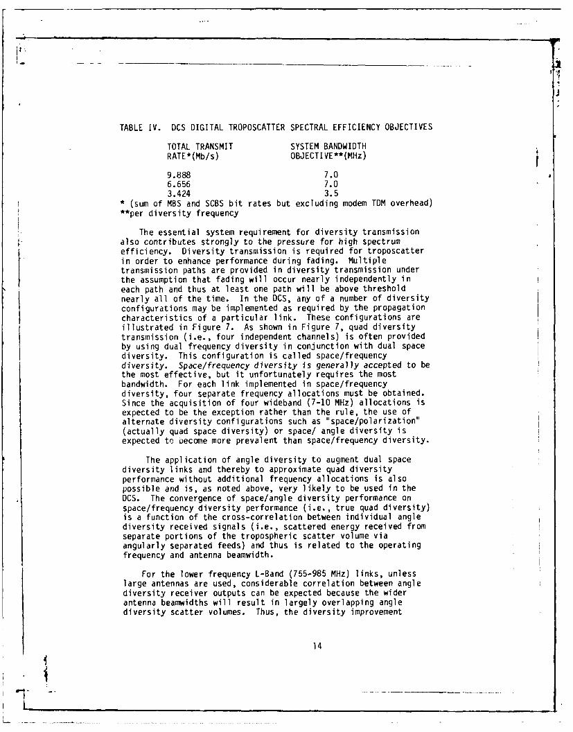
TABLE IV. DCS DIGITAL TROPOSCATTER SPECTRAL EFFICIENCY OBJECTIVES
TOTAL TRANSMIT SYSTEM BANDWIDTHRATE*(Mb/s) OBJECTIVE**(MHz)
9.888 7.06.656 7.03.424 3.5
* (sum of MBS and SCBS bit rates but excluding modem TDM overhead)**per diversity frequency
The essential system requirement for diversity transmissionalso contributes strongly to the pressure for high spectrumefficiency. Diversity transmission is required for troposcatterin order to enhance performance during fading. Multipletransmission paths are provided in diversity transmission underthe assumption that fading will occur nearly independently ineach path and thus at least one path will be above thresholdnearly all of the time. In the DCS, any of a number of diversityconfigurations may be implemented as required by the propagationcharacteristics of a particular link. These configurations areillustrated in Figure 7. As shown in Figure 7, quad diversitytransmission (i.e., four independent channels) is often providedby using dual frequency diversity in conjunction with dual spacediversity. This configuration is called space/frequencydiversity. Space/frequency diversity is generally accepted to bethe most effective, but it unfortunately requires the mostbandwidth. For each link implemented in space/frequencydiversity, four separate frequency allocations must be obtained.Since the acquisition of four wideband (7-10 MHz) allocations isexpected to be the exception rather than the rule, the use ofalternate diversity configurations such as "space/polarization"(actually quad space diversity) or space/ angle diversity isexpected to Decome more prevalent than space/frequency diversity.
The application of angle diversity to augment dual spacediversity links and thereby to approximate quad diversityperformance without additional frequency allocations is alsopossible and is, as noted above, very likely to be used in theDCS. The convergence of space/angle diversity performance onspace/frequency diversity performance (i.e., true quad diversity)is a function of the cross-correlation between individual anglediversity received signals (i.e., scattered energy received fromseparate portions of the tropospheric scatter volume viaangularly separated feeds) and thus is related to the operatingfrequency and antenna beamwidth.
For the lower frequency L-Band (755-985 MHz) links, unlesslarge antennas are used, considerable correlation between anglediversity receiver outputs can be expected because the widerantenna beamwidths will result in largely overlapping anglediversity scatter volumes. Thus, the diversity improvement
14
L - ,

. -, ,i -
. U UU rnur ur, (
). ,. _ 1, 1
5-G 1.
5-G M;GA
rnU

attributable to angle diversity will probably be only equivalentto quad space or "polarization" diversity. For the higherfrequency C-Band troposcatter systems, lower cross correlationbetween angle diversity receiver outputs is expected due to agreater confinement of angle diversity scattering volumesresulting from narrower antenna beamwidths. Thus for mediumdistance C-Band links, the performance of space/angle diversitycan be expected to approximate ideal quad diversity morefavorably. For most DCS troposcatter links which are expected torequire continued use of the lower frequency bands, the use ofangle diversity will likely be restricted to converting existingmarginal quad diversity systems to eighth order (space,frequency, and angle) or as a replacement for frequency diversityon DCS links with 60 foot (18 meter) and larger antennas. As a ruleof thumb, angle diversity will be useful for links with an antennabeamwidth to scatter angle ratio of 0.875 or less.
The most important component of the digital troposcatterfacility is the signal processing electronics; that is, theelectronics used for modulation, diversity combining,demodulation, and detection. This function will be implemented asa modem (developed under government sponsorship) and integratedwith the RF equipment necessary to provide a completetransmission capability, such as IF/RF converters, high poweramplifiers, and low noise receivers. Only a digital troposcattermodem rather than a complete digital troposcatter terminal wasdeveloped because (1) DCS troposcatter link requirements arerelatively few in number and (2) The majority of DCStroposcatter frequency allocations vary over three bands from LBand (UHF) to C Band (tactical SHF), depending on the path lengthand the area of deployment as indicated in Table V.
TABLE V. DCS TROPOSCATTER FREQUENCY BANDS
BAND (MHZ) GEOGRAPHICAL REGION
300-400 ARCTIC (one link)755-985 TURKEY, ARCTIC
1700-2700 ITALY, TURKEY, GREECE, WEST PAC, UK4400-5000 FEDERAL REPUBLIC OF
GERMANY (FRG)
Based on these observations, the full scale RDT&E development ofmore than the specialized signal processing function is not costeffective. Furthermore, it was observed that this function could bemade compatible with both the transfer characteristics of in-placeanalog troposcatter radios of recent manufacture and those ofcommercially available RF components. Thus, the procurement of adigital troposcatter modem for the DCS is currently planned. Thismodem will be compatible with the inventory radios listed in Table VIand the transfer characteristics of commercially available up anddown frequency converters. Utilization of this approach will permit
16
L

i-i
the digitization of servicable, in-place analog troposcatterfacilities, possible utilization of TRI-TAC radio RF assets, and thecost effective digitization of troposcatter facilities where RFequipment must be replaced and the TRI-TAC RF equipment can be used.
TABLE VI. MAJOR DCS INVENTORY TROPOSCATTER RADIOEQUIPMENTS AND CONFIGURATIONS SUITABLE FOR DIGITIZATION
RADIO/CONFIGURATION FREQUENCY BAND
AN/FRC-39A(V)
L: AN/FRC-123AN/MRC-85 755-985 MHz
AN/MRC-98AN/MRC-113AN/FRC-102
AN/FRC-56 1.7-2.4 GHz
AN/FRC-96 2.55-2.7 GHz
AN/FRC-97
AN/TRC-132, 132A 4.4-5.0 GHz
Figure 8 illustrates the interface between the radios listedin Table VI and the DCS digital troposcatter modem. As most ofthe equipments listed in Table VI are pre-1970 vintage, it isrecognized that certain minor modifications will be required topermit conversion of these radios to digital operation. Althougha detailed list of modifications has not yet been compiled forall radios, a fairly complete understanding of the requiredfunctional modifications exists. These modifications aresummarized in Table VII.
TABLE VII. TYPICAL ANALOG TROPOSCATTER RADIO MODIFICATIONS
FUNCTION MODIFICATION
RF/IF CONVERSION CIRCUITRY STABILIZE LOCAL OSCILLATOR CHAINSTO AT LEAST 1 x 10(-9) (SHORT TERM)
IF CIRCUITRY PROVIDE WIDEBAND (.k 10 MHz) 70 MHzDIVERSITY INPUT/OUTPUTS PRIOR TOAUTOMATIC GAIN CONTROL CIRCUITRY(AGC)
IF INTERFACE 50 OHMS, UNBALANCEDXMT LEVEL: -4 to +16 dBmRCV LEVEL: -10 TO -75 dBm
17
iL . - _____ ____ _ __ ,_ _

*10
&44
NW- c
0 0- 0
a~ C -3
C)
0, c
x~ u!
U
o tx x x '- V)
0 2c
18 4
4U-
w f.W c

Since large portions of the present DCS analog troposcatterinventory (e.g., AN/GRC-66, AN/FRC-75) are technologicallyobsolete and relatively costly to maintain, thought must also begiven to the specification and acquisition of RF components torefurbish troposcatter links using these aged radios (e.g., inthe Digital Terrestrial Upgrade - Turkey). Fortunately, onlycertain new RF components are required, since all signalprocessing and digital system interfaces can be provided by thetroposcatter modem itself. Figure 9 illustrates those major RFcomponents which, together with the digital troposcatter modem,
I. are necessary to provide a complete digital troposcattertransmission capability. Modularized RF components such asup/down converters (U/C, D/C) low noise amplifiers (LNA), andpower amplifiers (PA) can be assembled into cost effective,reliable packages and provided during the equipmentacquisition/system installation phases of a particulartransmission upgrade. Other RF components such as circulators,isolators, and dummy loads which are used in the in-place analogsystem can be retained for use after digitization. Utilizationof this approach, where appropriate, will permit the acquisitionof new solid state RF components and reliable power amplifierswithout purchasing an entire analog troposcatter radio withexpensive and complex combiner, demodulator, and service channelfunctions not required for use with the digital troposcattermodem. Since most DCS troposcatter facilities are geographicallyconcentrated, use of single RF components within a geographical areahas the advantage of permitting the establishment of the regionallycommon logistics base.
Performance assessment and monitoring are of particularimportance in troposcatter transmission due to potentialambiguities in identifying and differentiating equipment andpropagation related outages. Requirements and methods for thetransmission of troposcatter facility component status andperformance via the Service Channel Multiplex (SCM) function areunder review.
In the interim, Table VIII represents a list of troposcatterfacility performance/status functions along with their proposedmonitor output formats (contact closure, TTL level, etc) whichare likely to be required for telemetering to a transmissioncontrol facility. Additional station housekeeping functions suchas power amplifier power output and heat exchanger coolant levelmay be selected for monitoring and telemetering on a site-by-sitebasis, depending on the particular station manning level.
19
f- . _ _ ..- __ _ _

4-4
4--
3 0
0
L4.) d)
w 4) .01co 4 - to
C7C
S.- .- 0
4-;0 goF 4-)Lj)' r_)
CC~4 cc S.--c .- 449 Q. (
*0
LLJ 0
0
4-
IL-
04.,
0U,
~LLn
CCcc u E
CD x ~ C0/
*.-9-6 ) a,.C.--)
C) 20

A
o i i- H- - F-
H- 1 - I- - - M- m-( ~ ~ ~ C C) (ACD( A
L&U LO LUJ LUJ LL '
4D 2 ) CD CD CD CD CD CD
oD L.) L.) L-) L L) 2! M -
LLJ ~I C) H- H ) I=-(V2 C-)ULU L LJ U L LU 0A
ofX . U- U L H- - -j 0.
LUJ
-L F
CC--F- >.
C)J 2L - c
M:: C-LJJ (A) LU LU
7: (D H- =
H .LUI LL LU
=2 U L LUJm CC c
co LU L LU
co CD m C
-J 2: C)2
C> LUI 0 HH-- 0") u: H- c
H- = -cL ) 0 - C) CU H
-L U LU LU
Of w m- LJ (A 0C O H- CC3 -i C) =(A J -w H- Ix H- 0A L
) ~ V 0VIU U2:
H- LU LU) <~ - H-J H- L
LJ H- - 2: LU CL (
H- LU F- W~ 0Of-D(- H- - (A H. U- 2: (A w
2 ( LU~ 2i 2i LM (AOm 3c L2 .L>-L ALU
CO (A - =
LU n - - -. in L. 0- LU-
III. DIGITAL TROPOSCATTER TRANSMISSION TECHNOLOGY
1. THE DIGITAL TROPOSCATTER CHANNEL
Before discussing digital troposcatter transmission techniques,the phenomenon of troposcatter transmission from a digital viewpointis descrit2d. The troposcatter channel is typically described as alinear time varying, double dispersive (in frequency and time),fading channel. Figure 10 is an idealized representation of thescattering function of this type of channel and roughly representsits response to a series of transmitted impulses. For megabitdigital transmission (i.e., 3-12 Mb/s), Figure 10 correctlyillustrates that the time dispersion or multipath echo (i.e., widthalong the time axis) of this channel is much larger than the observedamount of frequency dispersion (fading) as related to a transmittedsymbol. This large multipath echo phenomenon (frequently extendingover one or more times the duration of a transmitted symbol) cancause a degradation in digital transmission performance due tointersymbol interference in which past symbol decisions interferewith the detection of present symbols.
Because intersymbol interference more drastically limitsperformance at megabit transmission rates, we initially describethe troposcatter channel in terms of its time dispersion or, asmathematically equivalent, in terms of its frequency selectivity.A description of the time dispersion or frequency selectivebehavior (i.e., doppler shift and fading statistics) of thetroposcatter channel is developed at the end of this section inpreparation for section IV, which presents DCS digitaltroposcatter link design objectives.
Due to the bandlimited linear nature of the troposcattertransmission process, its short-term time dispersive fadingstatistics (i.e., as measured over 10 minutes or less) aregenerally described in terms of a complex Gaussian, time-varyingtransfer function ] . This function is presented as a slicealong the time axis of the channel representation, portrayed inFigure 10. In this section, the nature and significance of thistransfer function is reviewed in terms of its effect on high ratedigital troposcatter transmission.
Since the effect of intersymbol interference on sequentialdata detection techniques is really a time based phenomenon, thetime domain representation of the troposcatter channel hashistorically provided the most intuitively satisfying description.Therefore, the response of the troposcatter channel is initiallymodeled in the time domain and related to its alternate frequencydomain representation only where necessary. Like any linearfilter, the troposcatter channel has an equivalent low passimpulse response, r(t,l ), which relates its output, w(t), to aninput, m(t), through the convolution integral. That is,
22
-- _ -_ _ _ _

N
.r,.
V€~1 C
Il 2/u
a S.-
U -~'U
L.
I 4P)-• r.- U
N v0
v u 0
23,, 0

I.- -
The power impulse response, r(t,C), is unique for a particulartroposcatter path and measurement instant, t_,, and its ensembleaverage over all time, t, is called the delay power spectrum,Q(Ca). For typical troposcatter links, Q(L) is nonimpulsiveand retains significant power for a nontrivial range of timedelay (typically on the order of 200-500 nsec).
The nonimpulsive nature of r(tC(t) stems from the physical
processes inherent in troposcatter propagation. In troposcatter,there are numerous scattering elements within the trcposphere whichare confined within a common volume subtended by the receive andtransmit antenna beamwidths. These elements are highly mobile andpower scattering from them causes a time varying temporal dispersionof the received signal (i.e., multipath propagation). In otherwords, a time specular transmitted signal (e.g., a narrow RF pulse)is transformed into an ensemble of scattered echoes by the channel,each arriving at the receiver dispersed or spread in time.Alternatively described, the variable separation of these scatteringelements within the common volume results in time varyingconstructive and destructive interference patterns at the receiverantenna, causing frequency selective fading. Thus, time dispersionand frequency selective fading are both manifestations of the samebasic physical process.
A standard measure of the frequency selectivity of atroposcatter channel is its correlation bandwidth. This parameteridentifies the largest transmitted bandwidth which can be expected tofade in a correlated manner (i.e., frequency independent or flatfading) within the channel, or alternatively, the minimum frequencyseparation required in a frequency diversity configuration to obtainuncorrelated receive signals. A method to derive the correlationbandwidth from the delay power distribution is described in detaillater in this section. Here, it is sufficient to note that thefrequency correlation function (from which the correlation bandwidthis obtained) is mathematically related to the delay power spectrumsince they form a Fourier pair. Thus, if we define 6$ as a quantityequal to the 2Wor double-sided rms value of the delay power spectrum(a convenient measure of its width) and S2Q as the correlationbandwidth, the following relationship can be derived from aregression analysis of (6$,Q) pairs as shown in Figure 11,
(2)IMI
Since the delay power spectrum itself is a time varying process,its variability is briefly explored. A quantitative illustration ofthe long term behavior of the delay power spectrum is seen in Figure12, which presents a distribution of 6Sas calculated from measureddata on a number of medium distance troposcatter links. Because of
24
........ ..

I F
1A
* Calculated Values
100 - Approximation
80
4J
.~60
C
a0
S- 40
C:U
20
0 .05 .1.15 .2 .25
dtRMS Dispersion (jisec)
Figure 11. Relationship of RMSChannel Dispersion to CorrelationBandwidth

1-A
j x
00
0 0-2t 0CD
w
00
-o
w iw
4-'
zz
00
0 U
(Sf1A VG~' 1O~IV10 CCS3cSO
26Ia
c-v ~-------.____ .- "-.4-

the Fourier relationship between the delay power spectrum and thefrequency correlation function, the behavior of QSis expected to beequivalently stochastic.
As implied by the long term cumulative distributions shown inFigure 12, QPr) is expected to be functions of both link parametersand path conditions. The expected variation of Q(0) with pathconditions (specifically changes in effective earth radius) is shownin Figure 13. It is instructive to consider Figure 12 and Figure 13in light of Figure 14 (taken from Panter [4]), which tabulate themeasured K factor distribution over a one year period and point tothe expectation of rather large values of fs as measured over anoperating year. As seen in Figure 12, measured data indicate worsthour values of 5 up to 2.5 times the yearly median value.Consideration of these figures implies the need for efficientaccommodation of large amounts of multipath propagation (on the orderof 400-500 nsec for medium length L or S Band paths) if reliabledigital transmission is to be achieved at required DCS capacities.
The channel is now described from a frequency dispersive ortime selective viewpoint (i.e., its "fading" behavior) because insection IV, system performance concepts for digital troposcatterlinks are based heavily on the temporal statistics oftroposcatter fades. Thus, a brief description of the fadingbehavior of the troposcatter channel is useful in clarifying thedigital troposcatter link performance analysis presented herein.
The fading behavior of the troposcatter channel istypically portrayed as resulting from a compound fading process.The short-term fading characteristic (measurable over portions ofan hour) is accurately described by Rayleigh statistics. As forits longer term behavior, the troposcatter channel experienceslarge diurnal variations (typically 20-30 dB) compounded by aseasonal variation on the order of 6-10 dB. Figure 15 portraysthese fading modes and their typical dynamic ranges. Because ofthis rather complex fading behavior, troposcatter fading isconventionally described in the overall sense as having a log -
normal distribution of short term median signal levels withshorter term (fractions of a second) fading about each medianvalue being described by Rayleigh statistics. Accepted methodsof calculating the magnitude and distribution of the long termpath loss can be found in NBS Technical Note 101 [r] and therecommendations of the CCIR [] for transmission frequenciesbelow 2 GHz. For frequencies above 2 GHz a new procedure hasbeen developed under the US Army's Angle Diversity Program[7].
Equally important to the discussion of troposcatterfading and its relation to communications system perfnrmance is adescription of expected fade rates. In particular, short termfading as described by the mean short term fade rate N, will bemost apparent (since long term fading is much sloweri and for thetroposcatter channel, strongly frequency dependent. The
27

0JJ
I . II
200 mi Path, smooth Earth
-I 30 ft antenna, 4.4 GHz
0CU K = 0.75
E -_ 2o 10
K = 1.00
______K =1.33
l-4
10-
10- _
0 .2 .4 .6 .8 1.0 1.2
ot, Time Delay (iisec)
Figure 13. Delay Power as a Function ofEffective Earth Radius
28
IvK:10

I.I
Eu"ropean ea I _ __90% of daa
iAnnuO med Wst month m d I i t thiCs rO 20
120 Overland por I K.133 K,095
Oie Se, one lard hO?. 1 10 Averag
H-gA altitude Path 1.00 1.0vlA00o (Scc, vof 4,OOO'
iI
o oveland path , .5*,|l(,.33 I Ko75
0 topath 55- l0ol t.90 1.20 sgao N4OW: Uf thiff K values to detleri atm. 9
1 1FigrT 4.Erpa aus,
o0 o ioi
M 8 0 0
29
L
-I*
k,.2,

L
j
.- ,-
- 0
-u
0-
.of
00
.. . . ..
I-
!II
30
9- u
,
- -_ - _ _ - - -- • -
I-

'I
dependence of short term fade rate on carrier frequency isexplored in [8]. For DCS troposcatter links (which operateprimarily in three bands between 700 MHz and 5.0 GHz) a mean faderate of 0.1 Hz represents a reasonable estimate and is usedin the subsequent development of digital troposcatter link designcriteria.
Because of the variability of troposcatter propagationduring unusual atmospheric conditions, periods of extraordinarypropagation can occur. The performance of troposcattertransmission systems during these anomalous periods can beenhanced or degraded depending on the limitations of a particularsystem design. There are two anomalous propagation modes thatare of major significance to DCS troposcatter transmissionengineering. The first anomalous condition is evidenced duringperiods when the refractive index profile of atmosphere isaltered. As illustrated in Figure 16(a), this condition resultsin the creation of a relatively low loss transhorizon propagationmode. This mode is generally identified by enhanced receivedsignal levels (typically increased by 10-20 dB) and a reducedfade rate (typically decreased by a factor of ten). This periodof large scale stationarity, called surface ducting, is alsoidentified by a decrease in multipath dispersion since ductingphysically stems from refractions from a propagation channel thatis strongly stratified and reduced somewhat in verticaldimension. The designer of digital troposcatter transmissionsystems must consider the occurrence of surface ducting so thatsaturation of the RF circuitry does not occur. For linkstransversing or parallel to coastlines in several geographicareas, the Mediterranean and S.E. Asia, surface ductingconditions are common.
Another form of ducting, elevated ducting, is illustrated inFigure 16(b). Elevated ducting can actually result in a period ofdecreased performance. This is due to a trapping of thetransmitted field away from the maximum gain orientation of thereceive antenna (i.e., away from the nominal great circle path).The probability of occurrence of elevated ducting in DCStroposcatter links can be ascertained by reviewing long termperformance data on a link basis, if available. If such data areunavailable, fortuitous periods of path loss testing is the onlyway that this phenomenon can be reliably detected. Localmeteorological data should also be reviewed, if available, forsevere index of refraction variations. The use of meteorologicaldata is expected to become more commonplace in both path lossprediction and furthering the understanding of the basic scatteringprocess.
The other major anomolous transhorizon propagation modeoccurs when an aircraft passes through the scatter volumeoutlined by the intersection of transmit and receive antennapatterns, presenting itself as the dominant scattering element.
31
1~1

-10-0
-40
S-10. 1000
-20- - 0
3D (
0 -500
-0~
. -40 aw "-3
TOM Rufracbt madus. M
(a) Surface Duct
(b) Elevated Duct
Figure 16. Atmospheric Ducting
32
- i , A

There are two separate effects which are felt duringthis anomaly. The first and most obvious effect is that atemporary increase in path fade rate (up to 100 Hz) isexperienced due to the doppler shift caused by specularreflection from the moving aircraft as it traverses the commonvolume. The second major effect is the temporary enhancement ofthe received signal levels due to specular reflection from thesurface of the aircraft. This effect must be considered in thedesign of the digital troposcatter modem to minimize theprobability of system synchronization loss due to thediscontinuity in propagation delay between aircraft scatter andthe normal troposcatter propagation mode as the aircraft entersand leaves the common volume. Figure 17 illustrates the RSL andmultipath dispersion characteristics typical of aircraftpassages.
2. IMPLICIT DIVERSITY
Frequency selective fading has historically limited theperformance of multichannel analog (FDM/FM) troposcatter systems.For FDM/FM systems, frequency selective fading of the transmittedspectrum due to multipath propagation causes an increase insystem noise called "path intermodulation" and limits theachievable channel capacity on most troposcatter links.Similarly, megabit rate data normally occupy transmitted spectraseveral times the value of the channel correlation bandwidth andthus are also vulnerable to digital path intermodulation or"intersymbol interference" resulting from independent fading ofvarious regions of the transmitted spectrum. However, with theuse of adaptive signal processing, advantage can be taken offrequency selective fading across the transmitted spectrum toprovide a significant increase in available system gain. Thisincrease in system gain is brought about by the coherentrecombination of uncorrelated, selectively fading segments of thethe transmitted spectrum. This in-band diversity phenomenon isdenoted as "implicit" diversity to distinguish it from thediversity gained through "explicit" means (i.e., additionalreceiver frequencies, antennas, or feedhorns in the case of anglediversity). The relationship of multipath propagation toimplicit diversity is briefly explored after which theperformance advantage obtainable through the use of implicitdiversity can be estimated. This area is addressed below asbackground prior to a review of digital troposcatter technologyand the subsequent derivation of link design criteria for digitaltroposcatter.
In order to more accurately treat the concept of implicitdiversity, a mathematical review of the details of frequencyselective fading is useful. While many channel models have beenproposed to represent the frequency selectivity or timedispersion of the troposcatter channel [3, 8, 9, 25], only the Belloand Parl model.; with their concept of the delay power spectrum
33
L_

I FI
DIFFERENTIAL 790DELAY Ins) 2S
0 0 030 60 90 120 tls)
RS.L -7
(dBm)
30 60 90 120 t s)
a: AIRCRAFT PASS- MODE I
DIFFERENTIAL tA0-DELAY Ins) 2
0 r " 0-'
30 60 90 120 t(s)
-65--
RSL -75-
IdBm)-854
30 60 90 120 tIs)
b: AIRCRAFT PASS - MODE 3r
790DIFFERENIAL
DELAY Ins) 245
30 *O t0 100 tls)
-Ss
RSL -65(dBm)
-75
0 60 90 30 t Is)
c: AIRCRAFT PASS - MODE X
F1qure 17. Examples of RSL and Dispersion MeasuredDuring Aircraft Passes
34
L I -
*1 - -- ~ - -~- ___ _ ~- - _ - - - - _ _ --

are based on physically fundamental concepts, and thus moreaccurately describe frequency selective behavior. In fact,these models have been shown to be especially accurate for pathsin excess of 150 miles (242 km) and therefore of direct utilityto the DCS. Both the Bello and Parl multipath dispersion modelsdepend, in turn, on the Wide Sense Stationary UncorrelatedScatter (WSSUS) representation for their theoretical basis.
i
According to the WSSUS model, we see that the delaypower spectrum can be defined as
where ra) was defined previously and represents ts eaverage. Recognizing that the WSSUS channel allows a Fourierhrelationship between the delay power spectrum and the complex
Two Tone Frequency Correlation Function, RCM ), it is possibleto express R similarly:
wh thee FCre tranBot the e ura n ansm dispend Wr is the
frequency spacing (in radians).
Figure 18 illustrates the shape of Rny calculated fora medium range UHF troposcatter link that is similar to many DCSlinks and that serves as an example for more fully discussingthe conshpt wee he bandwidth. Of specific interest isthe frequency correlation coefficient,p WI, defined as
,() C) (5)
The magnitude of p is a quantitative indication of thestatistical dependence which exists between two transmittedsignals. Previous work [10t has indicated that two fadingsignals can be treated as statistically t sdsimn rtoif P is onthe order of I/ev(0.4). Thus if RWLL is continuous, the valueof l by which one can obtain P =0.4 is definitive of thecorrelation bandwidth of the fading process (i.e., fading within
the correlation bandwidth is essentially nonselective). For thetroposcatter link modeled in Figure 18, p(.4) is on the order of5 MHz. This indicates that the transmission of an RF spectrum
occupying 5 MHz or greater is affected by frequency selectivefading. Frequency selective fading catastrophcally affects theperformance of conventional dgital transmission systems due to
the inability to maintain carrier coherence and symbol timingHowever, as winl be described later, the application of special
processing techniques can actually utilize this decorrelatedfading and develop an "in-band" or implicit diversity gain.
35

1.5
Path Length: 178 mlFrequency: 900 MHz
1.0 K =1.33
0
4-, o .8
0
4J)
S .6
Cr
1- .4 RQv04 .21r
.2
0 510 15 20 25
aFrequency Sepi4ration (MHz)
Figure 18. Frequency Correlation Function for aTypical Medium Distance Path
36

The mathematical relationship of the correlationbandwidth to the delay power spectrum and its relationship to theconcept of implicit diversity can now be developed. Continuingwith WSSUS channel notation, it is possible to express theshape of the delay power spectrum as an exponential afterSherwood [llj,
f(t) ~SaA ES ci] (6)
with Fourier transform
V(7)
where s is a link sensitive parameter which can be determinedfrom a curve fit of Q(a) to a specific delay power spectrum. Anexpression for GW), which is fairly representative of mediumlength and longer troposcatter paths, can be expressed indirectlythrough the envelope correlation coefficient:
P:L,7/( ) (8)
Thus, from a computed value of s it is possible to calculate acorresponding bandwidth, W, , which is suitable for estimatingthe implicit diversity potential of a particular link. Uponcalculation of w. , the order of implicit diversity can then beestimated by forming the ratio of the transmitted to correlationbandwidths.
That is, 7i
(9)
where ni = Approximate number of implicit (i.e., inband diversity)paths available for diversity reception
B = The transmitted bandwidth, as defined by its 10 dBpoints (MHz)
= Correlation bandwidth (MHz)- Largest integer operator (i.e., n + E = n + 1 for
0 1 < 1).The basis for estimating hi in the above manner is
appropriate. It has been shown that statistically independentsignals with large amplitude differentials (up to 10 dB) caneffectively provide a diversity improvement. Thus, even if onlya fraction of the scattered power falls outside of an integralnumber of correlation bandwidths, it still contributes in adiversity manner.
37
IL

, ig
Since the calculation of ni has as its basis the concept of adelay power spectrum which is defined as an ensemble average, nZreally represents the expected number of implicit diversity pathspresent in the channel. The subsequent application of nj to theestimation of average digital performance follows. For a particularmean signal to noise ratio, y0 , the mean DPSK bit error probabilityfor a channel with a known n.can be estimated as
<&> -&fix~](10)
where lo = (Mean signal to noise ratio modified to accountfor inband power sharing)
and n = n, ne (Total number of diversity paths which is theproduct of the number of explicit andsignificant implicit paths).
Figure 19 lllustrates the expected improvement in average errorprobability, (P , as a function of ni and nc . From this figure,it is obvious that implicit diversity has potential cost savings whencompared to explicit diversity techniques, which require additionalhardware or frequency allocations.
3. DIGITAL TROPOSCATTER TRANSMISSION TECHNOLOGY
Prior to the development of modulation techniques specificallyfor OCS application, digital troposcatter transmission was limited toless than 3 Mb/s. Digital modulation techniques such as BinaryFrequency Shift Keying (BFSK) and Phase Shift Keying (PSK) weretypically used. Because of the relative simplicity of thenonadaptive receiver structures implemented with these techniques,their performance was sharply curtailed by even a modest amount ofmultipath propagation [12]. Later, compound modulation schemes(e.g., FSK/PSK) were used to separate adjacent symbols in a bandwidthinefficient attempt to further mitigate the effects of multipaths [13].Bandspread systems using correlation receivers (e.g., the RAKE) werealso implemented to take advantage of the diversity inherent in thefrequency selective, multipath channel. However, the bandspreadingapproach was grossly inefficient in its use of transmitted bandwidth.
The advent of adaptive signal processing techniques [14, 15]together with the utilization of more efficient modulation forms suchas QPSK and Minimum Shift Keying (MSK), have enabled bandwidthefficient transmission at digital rates up to four times the previouslimit. The successful implementation of these techniques, with theirnear optimum utilization of implicit diversity has, essentiallyremoved the data rate limitations resulting from intersymbolinterference.
a. Cnmparison of the DAR and MD-918/GRC Madams. Over the past8 years the Army and Air Force have performed RDT&E on severaltechniques for DCS Digital Troposcatter implementation. After theirdevelopment and optimization, these techniques were evaluated in a
38
I
r - - ... . . w -

4
I 10-2 I
. number of explicit diversi ;ye paths
r i _ number of implicit diversi :y10 paths10-
[ .4-,
-
.0
-0 re='2, ni.l
S 0-5
.~~ e=2, niy2
av he=4 , ni~l10
nr=4, 2i=2
e=8, ni=l
10-0 5 10 15 20 25 30
Y9 Mean SNR of a Single Diversity Channel (dB)
Figure 19. Mean Bit Error Probability and ImplicitDiversity for DPSK
39
L--

series of performance tests to determine their relative applicabilityto the DCS and to provide a data base for technical specificationpurposes. The following discussion briefly explains the underlyingconcepts of these techniques and the results of the comparativeevaluation. For a more rigorous treatment of the technologies, thereader is encouraged to obtain the references cited in the followingdiscussion.
The first technique that is discussed is Adaptive DecisionFeedback Equalization (ADFE). This technique, described in somedetail in the literature f143, embodies a transversal equalizerstructure in which channel adaptation is accomplished via decision
V directed feedback. In general, equalization techniques can becategorized into linear and feedback classes. For diversitytroposcatter transmission, implementation of a linear equalizer, asillustrated in Figure 20, would utilize an ensemble of linearfilters, each operating on a particular diversity branch. Theequalized diversity signals could then be additively combined priorto sampled data detection. Linear modulation such as PAM, FSK, PSK,or MSK must be used due to the linear nature of the receiverstructure. Equalizer adaptation is typically accomplished via atraining sequence or pilot tone, depending on the implementation ofthe equalizer. However, decision directed adaptation can also beused.
A feedback equalizer, Figure 21, is similar in structure to thelinear equalizer with the exception that it provides data feedbackthrough a return path where a filtered version of the reconstructeddata sequence can be added into the data decision process. Thispermits partial cancellation of intersymbol interference frompreviously detected data bits. As with the linear equalizer, itsoptimum implementation consists of a series combination of matchedand transversal filters for each diversity path. The transversalfilter, if properly adapted, will reduce channel caused intersymbolinterference, while the matched filter will provide an implicitdiversity advantage through coherent recombination of the delayedcomponents of the multipath signal structure. Due to thebandlimiting imposed by practical system constraints, the receivedsignal is also bandlimited, and therefore a single realizabletransversal filter, suitably adapted, can provide the required seriesfilter characteristics.
As mentioned before, this receiver structure can be adapted viaa training sequence or through decision directed means. The currentADFE digital troposcatter modem prototype (MD-918/GRC) which wasdeveloped under the U.S. Army Megabit Digital Troposcatter Subsystem(MDTS) program, is implemented with decision directed adaptation.Adaptation via the transmission and processing of training bitsprovided by the modem is also possible. In fact, since the DCSdigital troposcatter modem will have an internal time divisionmultiplexer (TDM), the application of Adaptive Reference DirectedEqualization (ARDE) can be considered for this modem if the aggregate
40
L
L-

Y~ T Sybo -Interva-l-
41k
__ (D) _ __ aL .+

5 -p
Ix 0
W 10 (
4 .-.
4441
z 0-- 41
-
crN
+ W x
C7
L)J
ES CC
x I-
L-
X
427

TOM rate (sum of data inputs plus framing reference required foradaptation) can be within the bandwidth constraints specified insection II. The primary advantage of reference directed feedback isthat it is generally more robust under degraded transmissionconditions and thus is more desirable for low diversity (e.g., nonand dual) applications where deep fades occi.r more frequently orunder interference (e.g., jamming) conditions. However, for higherorder diversity implementations, ADFE is seen to be intrinsicallysuperior to reference directed feedback in that ADFE avoids anytransmission penalty attributable to an increased noise bandwidthresulting from the transmission of an additional adaptation bitsequence. Estimates of the required training sequence rate aredependent on the range of fade rates which must be accommodated. Asan example, satisfactory operation on links with fade rates of 1-10Hz is likely to require the transmission of a 150-200 kb/s adaptationframe rate.
Because the ADFE is described as a channel adaptive structure,the currently implemented adaptation technique is briefly described.As mentioned previously, both the linear equalizer and the feedbackequalizer can be adapted, via decision directed methods, to provideacceptable performance in a channel whose impulse response israndomly changing. The specific criterion used for adaptation in theMD-918 is based on minimization of the Mean Square Symbol Error(MMSE). As shown in Figure 21, the MMSE signal is formed in themodem from a voltage obtained from the difference between theintegrate and dump circuit output (prior to slicing) and a referenceamplitude. This error signal is then filtered to minimize theeffects of noise and then is correlated with appropriately delayedsamples of the input signal. These correlations are then used todevelop weights by which to weigh the received multipath components.While a truly optimum criterion would be based on minimum bit errorprobability, MMSE permits a greatly simplified implementation throughthe use of gradient estimation adaptation algorithms and performsalmost equivalently for most channels of interest.
The primary function of the feedback path is to reduceintersymbol interference and thus permit a less costly modemimplementation. For a given level of performance (defined in termsof minimizing intersymbol interference), fewer forward equalizer tapsare required when a feedback path is supplied.
The design criteria of the ADFE approach to digital troposcattertransmission are basically twofold. The first, and most important,is the ability of the ADFE to reduce the effects to multipathpropagation (i.e., intersymbol interference). This capability isdetermined by the number of forward and backward equalizer taps. Forexample, the use of a three tap forward equalizer with intertapspacing of one-half of the transmitted symbol duration together witha three tap backward equalizer will permit the near optimumequalization (i.e., result in acceptable residual intersymbolinterference) of diversity troposcatter paths with a or double
43

sided rms dispersion (2(3) of up to 1.5Ts , where Ts is the transmittedsymbol duration. For channels with greater than 1.5Ts , errorcorrection voltages obtained in the backward equalizer begin to besignificant and tend to prevent the buildup of a large amount ofresidual intersymbol interference. However, the performance of theADFE in the region of 2J.>1.5Ts is not discontinuous and is seen tobe strongly dependent on the explicit diversity configuration. Infact, the present ADFE in a quad diversity implementation willaccommodate paths with a 2Cof up to 2Tswith little ( 1 1 dB)degradation from its optimum operating point. A typical 300 mile(480 km) DCS troposcatter link has a yearly median multipath (2U ) onthe order of 200-300 nsec.
Eventually, as the rms channel dispersion increases beyond thecapability of the backward equalizer to correct for the estimatedintersymbol interference, the performance of the ADFE structure willbegin to degrade and exhibit an irreducible error rate. In order toextend the range of the equalizer to accnmodate larger multipathspreads caused by, for example, seasonal path variations on longpaths, the addition of more forward equalizer taps or additionaldiversity is usually indicated (although an increase of backwardequalizer taps to develop correction voltages based on a greaternumber of previously detected symbols may suffice and willbe less costly).
The second design sensitivity of the ADFE technique lies in itsability to utilize multipath propagation as implicit diversity. Thiscapability is related to the intertap spacing of the forwardequalizer. This can be easily visualized by considering theoperation of the forward equalizer in the time domain. In the timedomain, the equalizer is seen as being able to coherently combine "m"of a possible "n" scatter paths, where m is essentially the number offorward equalizer taps. For a particular rms channel dispersion,extension of overall delay capability beyond the expected range ofRMS dispersion will not in general provide any significant additionalimplicit diversity gain. This is due to the extremely low powercontained in scattered components received outside the 2Jdispersion(ff) of the particular channel. However, a significant number ofpartially correlated paths arriving within an interval bounded by the2- dispersion are present (the exact number of paths is functionallydependent on the composition and dynamics of the scatter volume).These paths can be optimally combined only if the intertap spacing ison the order of the granularity of the multipath structure of thechannel. Although many of these scatter-components are partiallycorrelated, they nevertheless can contribute effectively in adiversity manner (equaticn [10]). The span of the equalizer (i.e.,total delay or aggregate sum of the individual tap delays) will, ofcourse, remain constrained by the maximum 2U channel dispersionwhich must be accommodated. The present ADFE structure asimplemented in the MD-918/GRC Modem (three forward equalizer taps)can recognize no more than three inband paths. This implies asimilar upper limit in achievable implicit diversity (i.e., third
44
L

order). A reduction of the intertap spacing to Ts/3 or less wouldpermit a greater potential to utilize implicit diversity as long asthe same total forward equalizer span is provided.
The implementation of the ADFE as a prototype modem by the U.S.Army in the Megabit Digital Troposcatter Subsystem (MDTS)(MD-918/GRC) program has demonstrated significant performance gainsbased on a number of simulated link multipath profiles and actuallink tests at rates up to 12.6 Mb/s. These results are typified byFigures 22 through 24.
The second technique which was actively considered for DCSapplication is transmitter time gating with coherent detection. Thisapproach is currently implemented in the Distortion AdaptiveReceiver (DAR) Modem developed by the USAF [15]. The DAR techniqueemploys transmitter time gated QPSK modulation, Figure 25. Thedispersive troposcatter channel acts as a transmitter filter and will"fill-in" the guard space (T) or time gate, thus avoiding significantintersymbol interference as long as the guard space is less than thesignificant instant (i.e., 2 value) of the channel inpulseresponse. Since the channel fade rate (or, change rate) is alwaysvery much less than the transmitted symbol rate, the receiver willsee a serial stream of many symbol pulses, each identicallydistorted, with the exception that they will differ in phase inaccordance with the modulator phase state. If, through decisionfeedback, a coherent reference pulse train can be derived (mirroringthe path induced amplitude and phase characteristics of the receivedsignal), matched filter detection can be implemented with theimportant benefit of near optimum utilization of implicit diversity.
Because implicit diversity is key to the DAR technique andbecause development of a coherent reference is the key to therealization of implicit diversity, the details of the DAR referencegeneration technique are described. Basically, a reference pulsetrain is generated in the receiver at the IF frequency via an"inverse modulation" process where previous bit decisions are used tophase shift suitably delayed transmitted symbols such that all symbolphase states are equal (modulo 27). This "coherent reference" isthen applied to a recirculating filter where the referencesignal-to-noise ratio is improved by coherently adding referencepulses while the noise in the filter loop adds incoherently (i.e., asthe rms of the noise voltage). Additionally, the effect of decisionfeedback errors is reduced since no one reference pulse is uniquelyused to detect a transmitted symbol.
However, the utilization of transmitter time gating to providemultipath immunity is not without constraint. Lengthening the timegate to increase the guard time against multipath sacrificestransmitted power and eventually results in an unrecoverable powerloss and a spreading of the transmitted spectrum in excess of theallocated bandwidth. These factors strongly imply an upper bound onachievable data rate or acceptable multipath delay. A partial
45
L

.10- I
i 2
100
GJ Equivalent 8th Order4, 10- Diversity (3dB Imple-
mentation Loss)S.-
S.-.
4J
10-
080 0)52
rA9Ma N faSnleDvriyCanl(B
Fiur 22. 0DSOe-h-i efracYonson-Veoa(6Vi
6.3 Mean SNRofadSnl Diversity Canl(B
46

10- 1 I
-2 i10
10-03
Equivalent 8th Order00 Diversity0 (3dB Implementation Loss)F 4
0
0
-6A0
a- 0)V
10-7 Z-
-5 0 5 10 15 20rg Mean SNR of a Single Diversity Channel (dB)
Figure 23. MOTS Over-the-Air PerformanceYoungstown - Verona (168 Miles)C - Band, Quad Diversity6dBNF, AN/TRC-132A12.6 Mb/s
47
4T

44
10 Equivalent 8th Order Diversity-
A 0 6
10-
.448

TRANSMITTED PULSE TRAIN
RELATIVE PHASE 0 0
T ARECEIVED PULSE TRAIN (DISTORTED BY QUASI TIME-INVARIANT CHANNEL)
RELATIVE PHASE 0 Tn;
MATCHED FILTERVIDEO OUTPUT
MULTIPLIER ,INTEGRATEAND DUMP EPOCH TIMING
RELATIVE PHASE 0 0 0
REFERENCE PULSE TRAIN (IDENTICALLY DISTORTED)
Figure 25. OAR Waveforms (Ideal)
49
!-a -

m0
acgo
za "W Ln >W
41 w 00)Q0 00W -CIww U
wL Wi x- ILa- ui. 0 an
u. 0 CA1
W 00 0'
LL t +
a- 4-0
0 40
1.1 Z E-0
w $.
-J W06X 0
0W
I* 4J+1
cr -
50o
__ ___ __

solution to this problem involves the addition to the DAR of afeedback decision feedback equalizer (DFE), similar to thatimplemented in the ADFE technique discussed earlier. Figure 26illustrates the application of DFE to the DAR demodulator. As in theADFE, an error signal is formed from the difference between theanalog voltage present upon data detection and the present bitdecision (i.e., + or -1). In the absence of intersymbolinterference, the error signal will fluctuate about + or -1(according to the polarity of the transmitted bit) with the standardnoise variance. During periods of intersymbol interference, theerror signal will demonstrate an increased mean value, depending onthe strength of the intersymbol interference and the sign of theprevious and present bits. If the previous bit is of the samepolarity as the present bit, constructive interference will occur andobscure the development of the error signal. Thus, the error signalmust be developed over a period where the effect of an individual bitsense (+ or -1) can be averaged out. The averaged error signal ismultiplied by the interfering previous bit amplitude, inverted inpolarity, and added to the output of the integrate and dump filterprior to detection. This iterative process will continue until therms error signal is forced near zero. Through use of the DFE in theDAR, it was hoped to reduce the irreducible bit error rate limit by oneand possibly two orders of magnitude for a fixed spectral occupancy and,in many cases, permit a reduction in the duration of the time gate,thus resulting in improved spectral occupancy. However, in a OCSapplication it is expected that the maximum achievable spectraloccupancy will be about 0.7 bits/cycle, with 0.5 bits/cycle morerepresentative of the nominal application.
The performance of the DAR technique as implemented ist.ypified by Figures 27 and 28 which correspond to the same basic testconditions shown in Figures 22-24 for the ADFE. The present DAR withits near optimum utilization of implicit diversity offers a highpotential for low and medium rate (1-3 Mb/s) C-Band transmissionwhere the multipath is less extensive relative to an RF symbollength. The development of an optimized DAR configuration, withaddition of a workable DFE structure, was aimed at providing a viabletransmission alternative for most DCS requirements (including L andS-Band) of 7 Mb/s and less if the necessary RF bandwidth could beobtained (on the order of 10-14 MHz). However, implementationdifficulties prevented this expectation from being realized and theDFE augmented DAR is not considered practical.
The intrinsic advantages of the DAR technique are its simplicityin implementation (with obvious cost implications) and its highly 6efficient utilization of implicit diversity within its design limits.The major disadvantage of the DAR technique results from thebandwidth expansion caused by the transmitter time gating. Asmentioned previously, for most OCS applications, transmitter timegating will result in an expected transmission efficiency of about0.5 bits/cycle. The use of parallel transmission techniques, where aquad diversity system is split to permit parallel dual diversity
51

-2 0
0 00
-30
.4J -4
S.-S-S
Equivalent 8th order
diversity (3dB-5 Implementation Loss)
CU
V -6
0 4 8 12 16 20
oa, mean SNR of a Single Diversity Channel (dB)
Figure 27. DAR Over-the-Air PerformanceYoungstown - Verona (168 miles)2 dBNF, AN/?4RC-983.5 Mb/s L-Band, Quad Division
52

-- II
II-2
-3
-)
0I -0a
0 "-
r.-
S-6=Equivalent8th Order ,Diversity
V
-7 -IntersymbolInterferencePenalty
I , I0 4 8 12 16 20
Mean SNR of a Single Diversity Channel (dB)
Figure 28. DAR Media S~mulator Performance250 Mile .6 Antenna BW, k=4/37.0 Mb/s
53

transmission at one-half the link throughput (and require one-halfthe bandwidth) on each dual diversity channel, could alleviate thisproblem somewhat. However, as noted in section IIIB, theapplicability of parallel transmission is far from universal becauseof its necessary dependence on an extremely favorable link geometryto provide the needed implicit diversity conditions.
Given the parallel development of the DAR and ADFE techniques,they should be considered jointly. Perhaps the most directcomparison of the current ADFE and DAR implementations can be seen inFigure 29. Figure 29 describes the required bit rate SNR necessaryto obtain, as an example, an average bit error rate of 1 x 10(-5)as a function of the ratio of rms channel dispersion to transmittedsymbol duration, 2G/T . The quad diversity performances shown for theADFE and DAR are almost identical until the design limit of the DARis exceeded. At this point the required SNR increases asymptoticallyfor the DAR, implying the existence of an irreducible average biterror probability worse than 1 x 10(-5) for channels with 201/Tgreater than 0.5. In dual diversity, the comparison is moredramatic. Here the BAR outperforms the ADFE for all values of 29/Tless than 0.5. This is apparently due to its more efficient use ofimplicit diversity. The ADFE, on the other hand, exhibits a lessapparent optimum (i.e., a minimum required SNR) but possesses asignificantly enhanced multipath range over which it is capable ofoperating. In drawing conclusions based on Figure 29, note thatthere are a number of practical implementation factors which affectedthe performance summarized in this figure. These are:
o The DAR transmitted bandwidth (99% power BW), whileonly 1 to 1.25 times that transmitteL by the ADFE,is more uniformly occupied (i.e., the 3 dB bandwidthof the DAR is greater than the ADFE). Thispermits a greater potential for obtaining implicitdiversity on a particular path.
o The ADFE forward equalizer structure, as implemented, isfixed at three taps with intertap spacing equal to Ts/2.This limits both the implicit diversity obtained and theoperating range of multipath delay.
o The DAR coherent reference circuit bandwidth is notoptimized, resulting in an unacceptable implementationloss due to bandpass distortion within the demodulator.
o The ADFE performance at dual diversity ishampered by periods of high receive signal levelcombined with periods of large multipath (i.e.,i- Z,).The result is saturation of the IF amplifier/forwardequalizer circuitry which can cause error bursts.
Since the time Figure 29 data was taken, the following hardwaredevelopments have occured:
54
9F-" -. -
L-

30
25
LAA
20
0 ua4iv-AF
Dul iv
15
nAo
5
.5 1.0 1.5 2.0 2.5
2 Ratio of RMS Dispersion to Symbol Duration
Figure 29. Digital Troposcatter Modem Performance Summnary
55

I I
(1) A new version of the DAR modem as used in the AN/TRC-170(V)series of tactical tri-service digital troposcatter terminalsuses a dual interleaved time gated transmitted pulsetechnique. In this approach two time gated QPSK modulatedsignals, each at half the mission bit stream data rate andseparated slightly in frequency, are combined to yield atransmitted signal with only a small AN component as compared toa single pulse original DAR modem. This technique also increasesaverage transmitted power by nearly 3dB over the original singlepulse time gated DAR modem and extends the multipath capabilityfrom ,9-- 0.5 to - z;-1.0. The drawbacks to this approachare an approximate doubling in modem complexity and a small lossir, intrinsic diversity gain [15].
(2) Undar USA contract DAABO7-79-G-6231 the originalengineering mcdel MD-918/GRC modems are being modified to have DigitalRadio and Multiplex Acquisition (DRAMA) compatible mission data ratesof 3.232, 6.464 and 9.696 Mb/s and hot standby switch capability.Additionally, an improved AFE concept which interchanges the delayand demodulation functions shown in Figure 21 is being implemented.The new equalizer places the demodulator before the tapped delayline. Thus, a digital tapped delay line is used replacing theexpensive 70 MHz Surface Acoustic Wave (SAW) delay lines. The newequalizer improves the dynamic range of the modem which reduces thesaturation problem noted previously.
Considering these factors, the ultimate results of both the DARand ADFE development programs clearly support the technologicalfeasibility of digital troposcatter transmission. The key systemquestions are, can the DAR technique provide the multipathprotection required for DCS application, and also can bandwithallocations (i.e., resulting in 0.5 -0.7 bits/cycle) be obtained inthe appropriate frequency bands to support optimized application ofthe DAR? It is apparent from the data presented earlier that longterm variations of multipath dispersion of up to twice the yearlymedian 27 value (as predicted under nominal refractive conditions)can be expected. The DAR technique is unable to mitigate theestimated range of multipath delay expected on most DCS links over aservice year, particularly at the 6.4 and 9.6 Mb/s rates required byDCS digital transmission upgrade plans. Additionally, almost all DCShost nations have raised concerns that the digitization oftroposcatter facilities may reduce the bandwidth available for other,co-allocated services such as TV and mobile radio. As an example,the United States, in requesting digital troposcatter bandwidthallocations in the Federal Republic of Germany, was asked torecognize these constraints and ensure that fielded digitalequipments make minimum use of the allocated bandwidth consistent withthe state of the art. It is clear that given even a 10.5 MHz maximumallocation (which is about seven times the typical current FDM/FMtropo allocation for 48-60 VC's) the DAR modulation format cannotprovide the rate/bandwidth efficiency required for DCS-wideapplication. In addition, the necessity to operate in the UHF
56
I
L-

(755-985 MHz) and 1700-2700 MHz bands on longer tropo linkscritically affects the performance of the DAR technique. Asdiscovered during the combined U.S./NATO Digital Troposcatter TestProgram, sufficient RF bandwidth could not be obtained in currentlyavailable UHF radio RF equipment to support the DAR time gatingapproach at a 7 Mb/s data rate.
b. Other Modem Techniques. Other techniques such as theViterbi algorithm [16] and independent sideband detection [17] havebeen proposed. However, fabrication of the adaptation circuitry forthe Viterbi Algorithm implementation proposed for digitaltroposcatter, as functionally illustrated in Figure 30, is currentlyimpractical at rates greater than 5 Mb/s. Independent SidebandDetection is relatively inefficient in its use of transmitted powerdue to the necessity for a complex modulation scheme (PSK/FDM/FM).Studies have indicated that if the Viterbi Algorithm is successfully
implemented at high rates, its BER performance should comparefavorably with the ADFE technique. However, a disadvantage of theViterbi code for voice circuits is the delay (50-200msec) experiencedby the user.
c. Electronic Countermeasure (ECM) Susceptibility. Recentelectromagnetic vulnerability testing of the DAR and MD-918/GRCmodems has shown that both are sensitive to typical interfererwaveforms [18, 19]. However, the MD-918/GRC because of its robustADFE signal processing was less vulnerable. The reader is encouragedto review the classified references (18, 19) which contain detailsand results of the tests including jammer types, the degrees of modemvulnerability in terms of bit error rate and loss of bit countintegrity, and recommended design changes to decrease jammingsensitivity. Although the vulnerability testing did not includemodem spectrum occupancy variation, this aspect will be included ina future live link test program.
d. Summary. As a result of the aforementioned test andevaluation program, it has been shown that the ADFE technique, asimplemented in the MD-918/GRC modem, is superior to the DAR techniquefor DCS applications. In addition, because of the needed throughputdata rates of up to approximately 10 Mb/s with spectrum efficienciesof 1-1.5 b/Hz under multipath conditions of Q9 7-1.0 , it has beenjudged that the ADFE modem is the only technique in a sufficientlyadvanced (hardware) state to meet these requirements for DCSupgrades beginning in FY 82.
Although the MD-918/GRC is expected to cost up to 10 percentmore than the interleaved pulse DAR modem in equivalent quantities,the difference in link upgrade costs will only be approximately 5 to10 percent due to the relatively small total modem cost compared tothe overall link upgrade costs. A summary of major performancecharacteristics of the DAR and MD-918/GRC are shown in Table IX.
57
L-
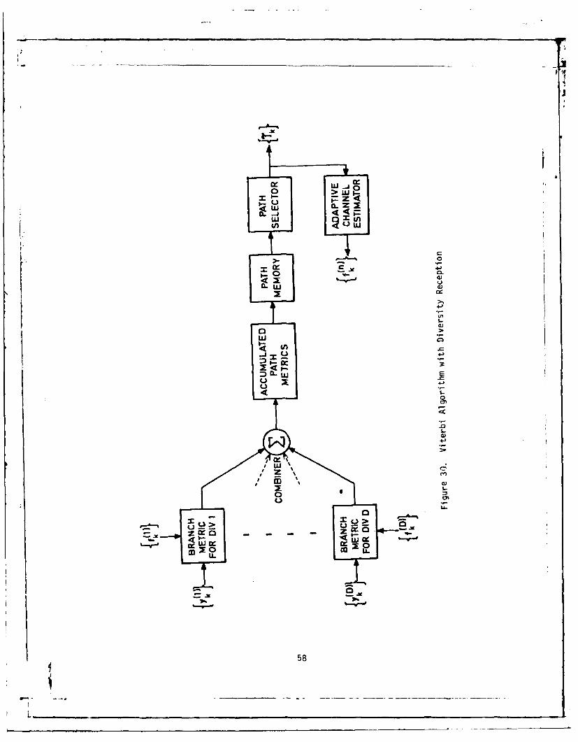
CL Z
_ 0
1: 4-)
4-)
0
W--
ED--
0).
2:-
urra '
U-.
58

TiBLE IX. COMPARISON OF MD-918/GRC AND DAR MODEM
DEMONSTRATED PERFORMANCE
PARAMETER DAR MD-918/GRC
BANDWIDTH 0.5-0.7 b/Hz 0.92-1.3 b/HzREQUIREMENT
DATA RATE UP TO 7 Mb/s UP TO 13 Mb/s
MULTIPATH 0 < 2C/T < 1.0 0 < 2J/T < 2.0
COST UP TO 10% MORE THANOAR
ECCM CAPABILITY SLIGHTLY LESSVULNERABLE
PLANNED USE TRI-TAC ARMY AND AFAN/TRC-170, DEB UPGRADES,
UP TO 2.3/4.6 Mb/s UP TO 9.7 Mb/s
Therefore, the ADFE technique is the preferred digital modemto meet the unique DCS requirements for data rate throughputcapability, multipath capacity, spectrum efficiency and user-to-useravailability.
59
-- _ _ _ °--
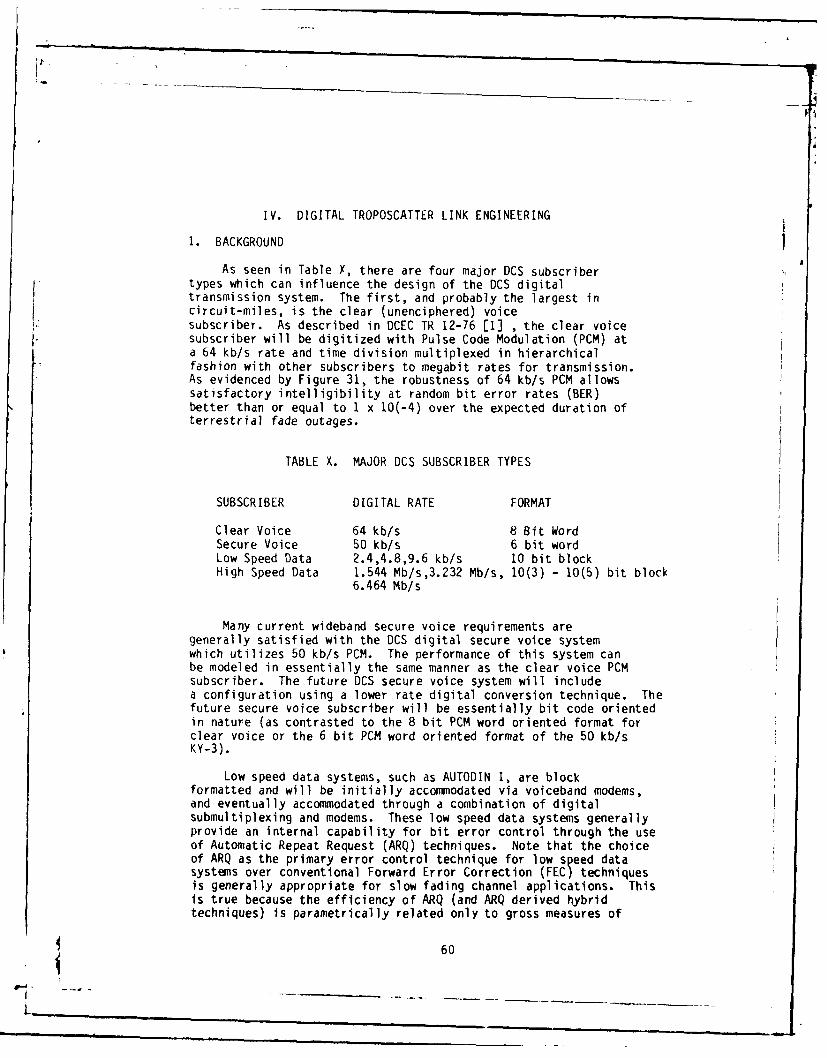
P.
IV. DIGITAL TROPOSCATTER LINK ENGINEERING
1. BACKGROUND
As seen in Table X, there are four major DCS subscribertypes which can influence the design of the DCS digitaltransmission system. The first, and probably the largest incircuit-miles, is the clear (unenciphered) voiceI. subscriber. As described in DCEC TR 12-76 [1] , the clear voicesubscriber will be digitized with Pulse Code Modulation (PCM) ata 64 kb/s rate and time division multiplexed in hierarchicalfashion with other subscribers to megabit rates for transmission.As evidenced by Figure 31, the robustness of 64 kb/s PCM allowssatisfactory intelligibility at random bit error rates (BER)better than or equal to 1 x 10(-4) over the expected duration ofterrestrial fade outages.
TABLE X. MAJOR DCS SUBSCRIBER TYPES
SUBSCRIBER DIGITAL RATE FORMAT
Clear Voice 64 kb/s 8 Bit WordSecure Voice 50 kb/s 6 bit wordLow Speed Data 2.4,4.8,9.6 kb/s 10 bit blockHigh Speed Data 1.544 Mb/s,3.232 Mb/s, 10(3) - 10(5) bit block
6.464 Mb/s
Many current wideband secure voice requirements aregenerally satisfied with the DCS digital secure voice systemwhich utilizes 50 kb/s PCM. The performance of this system canbe modeled in essentially the same manner as the clear voice PCMsubscriber. The future DCS secure voice system will includea configuration using a lower rate digital conversion technique. Thefuture secure voice subscriber will be essentially bit code orientedin nature (as contrasted to the 8 bit PCM word oriented format forclear voice or the 6 bit PCM word oriented format of the 50 kb/sKY-3).
Low speed data systems, such as AUTODIN I, are blockformatted and will be initially accommodated via voiceband modems,and eventually accommodated through a combination of digitalsubmultiplexing and modems. These low speed data systems generallyprovide an internal capability for bit error control through the useof Automatic Repeat Request (ARQ) techniques. Note that the choiceof ARQ as the primary error control technique for low speed datasystems over conventional Forward Error Correction (FEC) techniquesis generally appropriate for slow fading channel applications. Thisis true because the efficiency of ARQ (and ARQ derived hybridtechniques) is parametrically related only to gross measures of
60
L

'17
20j
V30 8 bit PCM, D3-~ =255
40
-c
a)
0
0
80
601
L-

• if
channel quality (block error rate) rather than to the actualdistribution of error events (as is the case with FEC techniques).It can be seen that the coding requirements for an effective ARQ datatransmission system are much less demanding than those required forFEC, since coding for ARQ requires only error detection (isolation ofan error to a particular data block) while coding for FEC requireserror correction as well as error detection (to a specific bit in theblock). For a terrestrial data connection, where mean fade outagedurations are expected to range between 0.5 and 4 seconds (dependingon whether tropo or LOS facilities are traversed), the use of FECtechniques to provide equivalent performance to ARQ is likely torequire decoded bit storage on the order of a few seconds. For manyhigh speed data systems, this approach is likely to be uneconomicalwith current technology.
An additional but nevertheless important factor regardingdata or record (i.e., message) traffic, is that the overallefficiency of the record system is only partly related to theefficiency of the transmission segment. In fact, otherconsiderations such as message preparation and delivery time arelikely to affect the end-to-end performance of a message systemmore strongly. Thus, the seemingly major deficiency of having theARQ data system run at 70-75 percent maximum throughput due to a highincidence of block retransmission requests, is actually less seriouswhen one considers the typical message delivery times currentlyassociated with AUTODIN I.
Clearly, this discussion presents only a heuristic treatmentof low speed data system performance over a terrestrialtransmission system. Nevertheless, the perspective related aboveis useful. In the overall design of a data system, other factorsbeside propagation path quality (within broad limits) willgenerally determine the grade of service provided by theterrestrial network to a data customer. In general, thepotential degradation of data service due to blockingprobabilities (in a switched data system) and lengthy messagepreparation and delivery times will be dominant. Thus, expendingadditional resources on the transmission plant to improve qualitybeyond a level acceptable for voice appears questionable withoutother improvements.
The introduction of satellite communications links into along haul data connection introduces a significant return pathdelay (for ARQ acknowledgement) and a noisy channel which isessentially nonfading. For the satellite link alone, FEC systemsare expected to perform better than most continuous ARQtechniques since random errors are likely to dominate the performanceof the nonfading satellite link. However, on an overall systemsbasis in which combined satellite and terrestrial transmission mediaare traversed, ARQ is likely to continue to be the major end-to-enderror control technique with FEC used on a bulk (multichannel) basisover the satellite transmission link to provide an additional
62
L

satellite link power margin. For efficiency, the ARQ low rate returnchannels for a number of data users can be submultiplexed atappropriate concentration points with other low speed digitai ;ignalsfor transmission and distribution to the originators. This actionavoids the necessity for high-rate full-duplex service solely toprovide a return path for data block acknowledgement.
From the foregoing discussion, it is evident that low speeddata systems of the type used in AUTODIN may actually be lessdemanding of continuous channel quality than voice, particularlysince reasonable efficiency can be obtained under channelconditions which would be disruptive to the PCM voice user (e.g.,a continuous BER of worse than 10(-4)). To support thisobservation, a quantitative treatment of low speed data systemperformance is given later in this section which considers theperformance of block formatted data systems as related to the conceptof error free block probability. The concept of error free blockprobability is appropriate since it identifies a lower bound for bothARQ and FEC data system performance and thus enables a subscriber todecide whether error correction techniques are actually required on aparticular system.
The channel quality requirements for high speed data andimagery systems (1.544 Mb/s and greater) are currently underdevelopment. However, it is expected that these systems willalso be block or frame oriented with perhaps somewhat longerblock lengths than the low speed data systems. As shown later inthis section, the performance of high speed data systems,employing block lengths of 10(3) bits or less, is not expected tobe the dominant influence in the choice of troposcatter linkdesign requirements. The expected performance of high speed datasystems could be further improved through the use of the ARQtechniques similar to those employed with low speed data. Apotential deficiency of ARQ in high speed data applications isthe absence of a real time, interactive capability of an ARQimplemented system, which results primarily from the time delayassociated with data block retransmission actions. However, itis expected that the end instruments of the high speed datasystem will remain analog, often with a human interface.Requirements for real time information transfer may actually besatisfied by near-real-time data transfer using ARQ or Hybrid ARQ(ARQ together with FEC) methods, even where extensive satellitetransmission is involved. The exclusive use of FEC techniques toprovide high speed data system error control on DCS LOS andtroposcatter systems is not likely to be feasible in the near andmid-term because of the storage requirements necessary to reducedegradations resulting from relatively long terrestrial channel fadesby data interleaving.
The preceding discussion implies the dominance of voicequality objectives in the development of digital troposcatterlink design requirements. Relative performance characterizations
63
i -P

II
of voice and data transmission are provided herein to demonstratethis dominance.
The ensuing development of digital troposcatter link performancecharacteristics will be outage oriented rather than oriented towardsmore conventional characteristics such as an average bit errorprobability, P This characterization is particularly appropriateand desirable for fading channels such as troposcatter and LOS wherethe "instantaneous" SNR observed at the nominal link operating state(i.e., under median propagation conditions) can be on the order of30-40 dB greater than when the link is deeply faded. In addition,the percentage of time during which deep fading actually occurs willbe quite small for links designed with adequate system gain andV diversity transmission. Since average channel characterizations suchas Pedo not directly reflect this behavior, they cannot provide theinsight necessary for the development of effective system designcriteria.
However, given knowledge as to the bit error distributionfor a fading channel such as troposcatter, this channel can becharacterized from a digital viewpoint (as an example, theprobability that a specific threshold bit error probability, p,will be exceeded as a function of the average SNR). Thus, it ispossible to characterize the behavior of the troposcatter channelin a more user-relevant form which can still be based on certaineasily measurable channel statistics such as received signallevel and order of diversity. Based on this concept andidentification of the performance thresholds for various DCSsubscriber types, a digital troposcatter link performancecharacterization will be developed which can be directly relatedto the PCM voice user through the concept of outage probabilityand, for the data subscriber through the concept of error freeblock probability.
In the design of DCS digital transmission links, various "fadeoutage ranges" and corresponding "fade outage probabilities" havepreviously been proposed in DCEC TR 12-76 for the clear voicesubscriber. In DCEC TR 12-76, a fade outage was defined as aninterval in which the bit error probability is equal to or worse than10(-4). To understand this definition, it must be recognized thatthe actual determination of a 64 kb/s PCM outage threshold for afading channel is much more difficult than merely calculating theprobability of an error in the most significant bit of a PCM word(i.e., an event which could cause a speech significant disruption)under random bit error rate conditions. Due to the temporal fadingstatistics of the troposcatter channel, a 10(-4) threshold bit errorprobability, Pe, for 64 kb/s PCM may actually be conservative, sincediversity troposcatter link fades below a Pe = 10(-4) will generallylast less than a second, and therefore the probability of an audiblespeech disruption is expected to be rather low. Thus an argument canbe advanced which, given knowledge of the expected value of P wherethe first PCM error occurs, would set the speech outage threshold at
64
I

an error probability greater (i.e., worse) than 10(-4) . However,the use of a bit error probability of 10(-4) as an outage thresholdis certainly more accurate than grossly specifying a Pe of 10(-4)(as previously required in the design of digital DCS LOS links) and,for the power and bandwidth limited troposcatter channel,significantly less costly. Therefore, in the absence of data on theperformance of PCM over troposcatter links, an outage threshold biterror probability of 10(-4) will be used.
In the following paragraphs, the expected fade outagestatistics (e.g., fade outage rate and fade outage duration) aremodeled for diversity troposcatter transmission. The fade outagecriteria developed in reference ,[i are used to define userquality requirements against which the DCS troposcatter linkdesign criteria are set. These criteria are given inTable XI for reader convenience. After this has been completed,the concept of service probability or confidence factor isexamined in light of its potential effect on troposcatter linkdesign requirements. This discussion provides a detailedrationale for requiring a specific service probability in thedesign of DCS digital troposcatter links.
TABLE XI. DCS PCM VOICE PERFORMANCE CHARACTERISTICS
FADE OUTAGE FADE OUTAGE FADE OUTAGERANGE (i) CRITERIA PROBABILITY (Pi)*
1 0.2 sec'outage 4 5 sec 7.5 x 10(-4)2 5 sec 'outage z 1 min 7.5 x 10(-5)3 2 c outages/min ! 5 2.5 x I0(-3)4 outages/min > 5 1 x 10(-4)
*Pi expressed as a percentagefor reader convenience
2. LINK DESIGN CRITERIA
Historically, the overall performance of FDM/FM troposcatterlinks was related to the percentage of time that a particularshort term (e.g., over 15 min) average SNR could be sustainedout of the long term distribution of short term SNR's. Thispercentage of time was interpreted as a time availability. Avariation of this convention is used here.
Specifically, DCS troposcatter link design objectives areformatted in terms of a specified short term SNR which must beexceeded all but a certain percentage of time for quadruplediversity transmission configuration. For this configuration,
65
--4 "
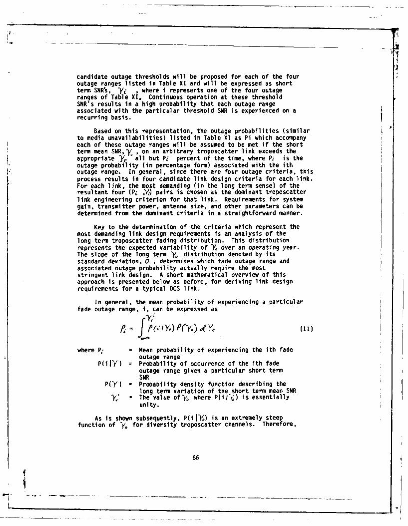
candidate outage thresholds will be proposed for each of the fouroutage ranges listed in Table XI and will be expressed as shortterm SNR's, -/i , where i represents one of the four outageranges of Table XI. Continuous operation at these thresholdSNR's results in a high probability that each outage rangeassociated with the particular threshold SNR is experienced on arecurring basis.
Based on this representation, the outage probabilities (similarto media unavailabilities) listed in Table XI as Pi which accompanyeach of these outage ranges will be assumed to be met if the shortterm mean SNR,y , on an arbitrary troposcatter link exceeds theappropriate y.. all but P1 percent of the time, where P; is theoutage probability (in percentage form) associated with the ith
[KL outage range. In general, since there are four outage criteria, thisprocess results in four candidate link design criteria for each link.For each link, the most demanding (in the long term sense) of theresultant four (Pi ,Y) pairs is chosen as the dominant troposcatterlink engineering criterion for that link. Requirements for systemgain, transmitter power, antenna size, and other parameters can bedetermined from the dominant criteria in a straightforward manner.
Key to the determination of the criteria which represent themost demanding link design requirements is an analysis of thelong term troposcatter fading distribution. This distributionrepresents the expected variability of -Y. over an operating year.The slope of the long term 'Y, distribution denoted by itsstandard deviation, C , determines which fade outage range andassociated outage probability actually require the moststringent link design. A short mathematical overview of thisapproach is presented below as before, for deriving link designrequirements for a typical DCS link.
In general, the mean probability of experiencing a particularfade outage range, i, can be expressed as
f i /Yo) fy) Ile.(11)
where P. = Mean probability of experiencing the ith fadeoutage range
P(i1Y) = Probability of occurrence of the ith fadeoutage range given a particular short termSNR
P(CY) = Probability density function describing thelong term variation of the short term mean SNR
= The value of-yo where P(ilj;) is essentiallyunity.
As is shown subsequently, P(i IYo) is an extremely steepfunction of " for diversity troposcatter channels. Therefore,
66
iL-

P, will be essentially determined by periods of time when Yo issmall. Equation (11) is generally very complex to evaluate sincejoint statistics of SNR and multipath dispersion must beconsidered. A computer program has been developed by the U.S.Army under DCEC auspicies which evaluates this expression on anumerical basis. To facilitate understanding of thecomputational method, an approximate method is used to derivelink design requirements for a hypothetical troposcatter link oftypical parameters. Because of the rapid variation of P(ily0 )with y0 , an appropriate approximation is
f,. [ (12)
Pi and P(i J-Y,) are as defined previously and P( Yo S -Y ) isthe probability that the short term SNR, Y(, , is equal to or lessthan some 7;
Also described previously, values of _Yo are chosen to make= . Thus
- Yo (13)
where rA are the threshold values of -y. which result inP(i r) C I.
Finally then, by the above model, P(7o,/Y) is simply thefade outage probability associated with the ith outage range.
Beginning the detailed development of link design criteria,it is seen that PO , or the short term probability that an outagewill be experienced (i.e., a probability of bit error rate equalto or worse than 10(-4) given a particular short term SNR) on adiversity troposcatter link, can be estimated via the methoddeveloped by Osterholz and Smith [20]. For a quad diversity link, P.can thus be expressed for a particular }'Y as
(po UD) - ,(14)
where (Po/i) = Probability of a fade outage given a short termSNR, /
b = (2 x (4))-in(b)
= Short term SNR (Actual Ratio, not in dB)m = 4nj (quad diversity).
67
Li

The fade outage performance, as expressed by (14), is assumed tohave a second order (n =2) implicit diversity enhancement. Thismeans that one over the information rate is greater than the rmsmuitipath dispersion but less than twice the rms multipath. Thisassumption is considered reasonable for many DCS troposcatter paths.Figure 32 illustrates the behavior of equation (14) for quad diversitydigital troposcatter link configurations as a function of/,. Forcomparison purposes, measured fade outage data are provided alongwith the calculated curve. These data were taken on a 187 mi (301km) C-Band link at a nominal data rate of 9.4 Mb/s.
Having characterized fade outage probability in thecummulative sense, the expected temporal distribution of theseoutages is now examined. Again using the expressions developedin reference [20], conditional mean outage frequency and durationstatistics can be expressed for diversity troposcattertransmission as:
o Mean Outage Rate)7
(A- -)! 7(15)
where,, b and m are as defined previously and N is defined asthe mean channel fade rate in Hz. Equivalently, the Mean TimeBetween Fade Outage (MTBFO) or the mean interarrival time ofoutages can be expressed as V/0
Further, knowing MTBFO and (P.J ), the mean duration of an
outage, ?o can be expressed as
o Mean Outage Duration
(,jy-) = (P Jo) (16)
The distribution of fades relative to the mean can be determinedfrom assumptions of a narrow band Rayleigh process and expressedas
~ I,(Yi.~) xjU~ 7 ](17)
where u = 11 is the modified Bessel function of thefirst order, and P(t) is the probability that an outage will havea duration of t seconds or less. Figures 33 through 35 illustratethe relationship of T7 , t. and P(t) to Ye, for diversity digitaltroposcatter transmission.
68
L

9.4 - 0 I/S MEAUE DAA3 OB MODEM MPLEMEh"TA-TlON LOSS
2
DIERSITY
10-4 !
0 5 10 15 20 26 30
Y.. SHORT TER MAN SO (6)
Figure 32. Troposcatter RF Link Outage Probability
69i

1 0 1 T1f--rr-- ~ rr
10-2
- -
- = H-
QUADDIVERSITY I.;
10 4
10-
5 I I I I I ! u ; !I
I 1 I
10- 6
D I6 j jR . ..T
0 5 10 15 20 25 30
Y. SHORT TERN IEMI SNR (OB)
Figure 33. Troposcatter Link Outage Rate

10 1TT-r W v IT 1T 1 1
QUAD DIVERSITY N = 0.1 HZ
0 - 2
o UDVRSst~H
0
0-43
0S 10 15 20 25 30
* SHORT TCRM W(AN SNR (OB)
Figure 34. Troposcatter Link Outage Duration
71

7J
6
5 - _ _ _ _ _ _ _ - _ _ _ _ _ _
3
2 ___
5 _ _ _
0 00 .0 f.0 3 0 7 ; 9 9 9 99
27

J
The information in Figure 33 implies that Mean Time BetweenFade Outages (MTBFO with duration t,, t,- tR ) can be estimatedby calculating
(At1-4 z-1,s ,, a / -K ) .(18)pr ) -Ar,)2
The scaling of MTBFO (t,, t.) to give an estimate of thenumber of outages that will occur during a call minute is simply
The above discussion leads to an expression for the relationshipbetween Yo and the probability of fade outage per call minute. Thisexpression determinesthe , at which operation results in a nearunity probability of experiencing the first and second outage rangesof Table XI (i.e.. / , #R ). In addition, under certain conditions of'Yand mean fade rate, the troposcatter channel is expected to faderapidly enough to cause several fade outages during a call minute;hence the third and fourth requirements in Table XI are necessary.The probability that between two and five fade outages will occurduring a minute and the probability that more than five fade outageswill occur during a minute can be estimated from equation(15)bydetermining the values of Y. for which
< 0-7)L
Link operation at or below these values of Ydenoted asYT
and r, results in a near unity probability that outageranges 3 and 4 will be experienced on a recurring basis.
The association of a particular Y, i with its appropriate P,(to be written: ( ; , Pi )) as shown in Table XII will thenconstitute a candidate link design.requirement. Thedetermination of which of the ( -Y,, P.) pairs in fact representsthe most stringest link design requirement can only beaccomplished by considering the long term distribution of shortterm SNP's tyoical of DCS troposcatter paths. The objective ofthe ensuing analysis is to determine, for each transmissionconfiguration, which of the candidate link design requirementslisted in Table XII requires the highest long term SNR.
TABLE XII. CANDIDATE LINK REQUIREMENTS(HYPOTHETICAL LINK)
FREQ BAND DIVERSITY "r (dB) > ALL BUT Pi OF THE TIME
i=2 i=3 i=4 i=5
10 5 4 N/A
L,S,C QUAD P2=(0.075) P3=(0.0075) P4=(0.25) P5=(0.01)
73
L

I4
P4 is expressed as a percentageoY. is expressed in dBi is defined as outage range
As outlined earlier, outage probabilities in the outageranges identified in Table XI necessitate link.design thatinsures that a specific short term mean SNR, /' , is exceeded allbut Pi, where Pi is the outage probability associated with theirw outage range.
Determination of the most demanding of the ( V/, P,,) pairslisted in Table XII is begun by considering the long termdistribution of short term SNR typical of the troposcatter channel.This long term distribution is usually described as being lognormal. That is,
?___ ____-Yo (20)
where P(XYo<) is the probability that the mean SNR is
less thany,, -Y is an arbitrary short term SNR (hourly mean) indd)Y is the long term (i.e., yearly) SNR in dB, and Cris thestandard deviation of Y, abouty , also in dB. The standarddeviation of the distribution, or , is roughly indicative of theexpected rate of change of the short term SNR over time. Asshown in Figure 36, most DCS links are expected to exhibitstandard deviations on the order of 4-8 dB. In general, theshorter links will exhibit higher observed standard deviations.Since most DCS troposcatter paths are less than 300 miles (480 kin) inlength, large measured standard deviations are not surprising.As an example, Figure 37 is a distribution of -Y, derived frommeasured received signal level data for a typical medium distanceDCS troposcatter link [21. Values were calculated in a 6.464Mb/s bit rate bandwidth (g6 equivalent VF channels).
From observations of the slope of the long termdistribution of Y for this typical link as evidenced by T = 6dB in Figure 37, the expected range of -Yfor DCS troposcatterpaths and the typical link design requirements (Table XIII), itis obvious that the most demanding link design requirements arerepresented by the outage range number two. Based on this analysis,the hypothetical digital troposcatter link requirement ispresented in Table XIII and denoted as () ,Pq).
TABLE XIII. OCS LINK DESIGN REQUIREMENTS FOR A TYPICAL DIGITALTROPOSCATTER LINK
BAND DIVERSITY LINK DIVERSITY REQUIREMENT( -YR, P
L, S, C QUAD (10, .075)
*PA expressed as a percentage
expressed in dB
74
L

t 12
[ 10
8 Annual Std. Deviation
0
4
Winter Month Std. Deviation
Range of DCS Applications
t t0
1.-
o Effective Distance (Mile)
Figure 36. Standard Deviation of Path Loss vs Effective(Angular) Distance
' 75
I- _.__

A4 I
iI
DCS LINK T0224(IRAILION-MT.
PATERAS)
SIGNAL TO NOISE RATIO DIST.
3A ( 6.464 MbpsJ
BASED ON 30 DAY RSL RECORDINGO'z 5.6 db
S24 -24
I
0
0
4
01 *1 I 10 30 50 70 90 99 99 9 9999
PERCENTAGE OF TIME Yo GREATER THAN ORDINATE
Figure 37. Long Term Distribution of y for a
Typical DCS Troposcatter Ho
76
_ _ _ _ _ _ _ _ _ . .. ,

(Note: The above requirement was derived for a hypotheticallink. Tropo link design will remain a link by link task and willvary from the above criteria on occasion).
The tandeming of troposcatter links should not appreciablydegrade the performance of the transmission system as a wholesince the worst case effect (i.e., correlated long term fading onthe tandemed links) will linearly decrease the interarrival timeof outages with the outage duration statistics remainingessentially unchanged. For links with uncorrelated long termfading (or tandem connections extending over large areas), theoverall outage statistics are likely to be almost totallydetermined by the link with the lowest Yo (or the links with thehighest long term fading correlation) at any time. Perhaps moredirectly, it should be pointed out that the originalprobabilities specified in reference Cl and repeated in TableXI were, in tact, allocated on a mileage basis. Thus, whetherthe 600 mile DCS reference channel described in reference (1 ismade up of all LOS, all troposcatter or a mix of terrestrial
media, the overall channel quality should remain withinspecification.
3. ERROR FREE BLOCK PROBABILITY
The concept of error-free block probability attempts toprovide a subscriber with an indication of the expectedtransmission efficiency of his data circuit. In general, for alink designed to provide a particular ^V. (short term SNR), theprobability of receiving a data block of n bits in duration withat least one error can be estimated with the assumption that biterrors and block errors are approximately related by
P(block error) = ni. P(blt error). (21)
Adapting expression (15), the probability of receivinga 10(3) bit block with at least one error can be written as
(Aei) (22)
where P(BEIY) = Probability of receiving a block in error given
bo = (2 x 10) 3)
1 = In (bs)m= -
As noted earlier, the long term performance of most DCStroposcatter links is accurately described in terms of a log
77
I__*

normal distribution of y0, having a standard deviation on theorder of 4-8 dB. Based on this description, it is expected thatblock error probabilities will be distributed similarly, with theoverall probability (i.e., on a long term basis) of a block errorheavily influenced by periods of large, long-term path loss (e.g.,during the late afternoon hours). The mean long term probabilityof receiving a data block in error is then formulated in the samemanner as the PCM voice outage analysis developed earlier.That is,
R?(A IYAT) P(-Y Yj) =;P( EI)'P . (23)
For a data block of 10(3) bits, Figure 38 illustrates thedistribution of P(BEIY.). As specified in reference [1I1, theprobability of receiving a 10(3) bit block in error for thereference troposcatter hop must be no greater than 2.5 x 10(-3).The link design requirements listed in Table XIII, which were
derived on the basis of PCM speech quality considerations, willpermit the achievement of a P(BEIY)'PA which is less than 2.5 x10(-3) that a 10(3) bit data block will contain one or more errorsdue to a media caused outage. Therefore, DCS PCM speech qualityrequirements are seen to require the most demanding link design.
4. SERVICE PROBABILITY
The concept of service probability and its impact on digitaltroposcatter system link design are discussed in the followingparagraphs. Because of demonstratedly significant variability ofthe long term performance of identically sited and configuredtroposcatter links, the concept of service probability(essentially a link design confidence factor) was developed bythe National Bureau of Standards (NBS) [5]. As an example, atroposcatter link design with a service probability of 0.5 impliesthat out of 100 identically configured and sited links, 50 links arelikely to meet or exceed the link design requirements.
In an attempt to achieve reliable transmission linkperformance in the OCS, analog troposcatter links were generallyengineered to provide long term performance at serviceprobabilities of 0.85 to 0.95, depending on the function of the link(e.g., a tail or backbone). Unfortunately, significantincremental costs in the form of additional required system gainresulted from link designs at these service probabilities, andthus a number of analog DCS troposcatter links were actuallyinstalled at lower service probabilities 'e.g., 0.5). Becausemany of these links are being considered for upgrade anddigitization, it is then useful to reexamine the sensitivity ofsystem gain to variations in service probability for digitallinks. Figure 39 illustrates this sensitivity and shows theincremental system gain necessary to meet, for a medium distance
78
I

ItI
10"21 1 1 1 i fv I I I I I I I I -l.
0 /7. IBS MERE DATA7110 BITS/BL0CK
ao 101 3 0 O6 IF IA|IMl'
. ,- CTEO ERROR A E BLOCKP O BILITy
02 0 0
00
0%
10-
0 5 10 15 20 25 30 ISHORT TERM MEAN SNR (OB)
Figure 38. Troposcatter Link Block Error Probability
79
1 1

L4
1 .5
Ij
1.0
.8
- .6
o n .4
.2
I I I I0 5 10 15 20 25
AG , Required Incremental System Gain- Normalized (dB)
Figure 39. Incremental System Gain as aFunction of Service Probability
80
*I _ _ _ _ _
link, the quad diversity C-Band link design criteria listed inTable XIII, at varying service probabilities. Figure 39 revealsthat the incremental system gain,AG,, increases rapidly withincreasing service probability, Ps . The apparent assymptoticbehavior of dG, which is observed as Psincreases beyond 0.95parenthetically suggests that a small number of anomoloustroposcatter links can be expected in a large network such as theDCS no matter how much care is taken during the initial linkengineering phase.
As mentioned before, the design of a troposcatter link toprovide the required performance at a service probability of 0.5 willresult in significantly reduced system gain requirements and cost(7-1OdB/$200K per link). A question then naturally develops as towhether a specific link connectivity is worth the increasedexpenditure of funds to provide the increased system gain (and hence,additional design confidence) or whether a design to a minimalservice probability (.5 to .75) will be sufficient. To answer this,the importance of actual circuit allocations on a particulartroposcatter link and the availability of alternate routing must beknown, a subject which is beyond the scope of this report. However,it is known that many DCS troposcatter links serve remote areas whereextensive alternate routing during periods of link outage isunavailable (e.g., Italy, Greece, Turkey). In view of this, it isprobably accurate to assume that all DCS troposcatter multi-channelconnectivity requirements include individual channel requirements ofsufficiently high priority that a link design to a minimal serviceprobability will not be sufficient. Also, the cost of even the mostaustere troposcatter system together with alternate routing make itprudent to insure significant link margin so that the system willperform satisfactorily when installed.
Considering the options for increasing system gain availableto the system designer (e.g., increasing antenna size and poweroutput and reducing receiver noise figure), it is readily seen thatan increase of no more than 10 dB of system gain is technologicallyreasonable for most DCS links assuming an installation that providesa service probability of 0.5. An incremental system gain of 10 dBrelative to the installed link service probability of 0.5 will movethe achievable service probability to approximately 0.95 on mostlinks. Based on this, it is recommended that the RF equipment usedon all OCS digital troposcatter links be upgraded if necessary toprovide a service probability of 0.95 unless specific exception ismade due to ready availability of alternate routing, a lack of userpriority, a sufficient quantity of accurate measured path loss data,or operational expediency.
81

V. TRANSMISSION SYSTEM ENGINEERING CONSIDERATIONS
The successful development of a megabit digital troposcatter
transmission capability is not sufficient to guarantee its
applicability to an operating communications system such as the
DCS. Prior to planning for the actual implementation of digital
troposcatter links, a number of system engineering issues must be
addressed to insure that prototype digital troposcatter
transmission hardware will be compatible with the operational
constraints of the evolving DCS. These issues are summarized in
Table XIV along with their impacts on the design of specific
digital troposcatter components.
TABLE XIV. DIGITAL TROPOSCATTER SYSTEM
ENGINEERING ISSUES AND COMPONENT IMPACTS
COMPONENT IMPACT
~ANTENNA &
SYSTEM ENGINEERING ISSUE MODEM RF EQUIP FEED SYSTEM
o Link Capacity P S
o Bandwidth Availability P P S
o Conversion to Higher S P P
Frequencieso EM Vulnerability P P S
o Cost/Performance Balance P P S
o Facilities Design S P P
o Digital Equipment P N N
Compatability
LEGEND
W~Piimary ImpactS = Secondary ImpactN = No Major Impact
82
L

1. LINK CAPACITY
As discussed earlier, troposcatter transmission of data rates upto 12.6 Mb/s is technologically feasible but possible only at theexpense of significant system gain due to broadband transmissioncomponent losses. Fortunately, an estimate of DCS troposcatterrequirements as summarized in section I indicates that approximately86 percent of the projected DCS troposcatter link requirements can besatisfied at input data rates of 6.464 Mb/s or less and all currentlyprojected requirements can be satisfied at 9.696 Mb/s or less. Thedevelopment of broadband power amplifiers (i.e., 10 MHz, 1 dB BW) atC (4.4-5.0 GHz) and S (2.5-2.7 GHz) bands with 10 kW rated outputpower will allow the reliable transmission of rates greater than9.696 Mb/s. These objectives were being addressed in the U.S. ArmyEfficient Reliable High Power Amplifier (ERHPA) program at S and L(755-985 MHz) Bands [22]. However, the change in lead MILDEPresponsibility for DCS troposca*ter to the Air Force has caused thisR&D effort to be deferred pending definition of requirements. Theintrinsic bandwidth limitations of L-Band high power klystron tubesare likely to limit DCS troposcatter transmission to rates of 9.696Mb/s or less in the 755-985 MHZ frequency range The development ofC-Band klystrons with sufficient bandwidth has occured under theAN/TRC-170 full scale development program.
2. BANDWIDTH AVAILABILITY
Because DCS troposcatter links presently operate in the755-985 MHz, 1.7-2.7 GHz, and 4.4-5.0 GHz frequency bands,bandwidth allocations vary widely. Current FDM/FM bandwidthallocations are 3.5 MHz or less in these bands. Discussions withhost nations have resulted in the possibility of a 7.0 MHzallocation and on an exceptional basis, a 10.5 MHz allocation fordigital links. Since the majority of the projected digitaltroposcatter link requirements identified in section I will beimplemented at 6.464 Mb/s, digital troposcatter facilities mustbe capable of transmitting 6.464 Mb/s plus a radio overheadcomposed of a 192 kb/s service channel and radio framing in nomore than 7.0 MHz; also 9.696 Mb/s plus radio overhead must betransmitted in no more than 10.5 MHz. As a design objective,transmission of 9.696 Mb/s plus radio overhead in 7.0 MHz is desired.In frequency bands where 7.0 MHz allocations are presentlyunavailable, a 6.4 or 9.6 Mb/s throughput requirement may besatisfied by implementing a particular link in quad space-anglediversity, rather than using space-frequency diversity and acqu'ringmultiple adjacent narrowband allocations, through a special hostcountry agreement. This agreement could possibly be based onpromised link deactivations elsewhere within the '"ost country.
The feasibility of obtaining two contiguous narrowbdndallocations is not as remote as may first appear.Broadband transmitter noise resulting froc, lystron amil 1lewhich provide the high effective rddlated ,owvyt ty ,, ',
4;

A107 303 DEFNSE COM WAICATIO S ENGINER NG CENTER RESTON VA P s 17/2.1APPLICATION OF DIGITAL TROPOSCATTER TO THE DCS.lulSEP 80 J L OSTEROLZ. 0 J CYSROVSKI
UNCLASSIFIED DCEC-TR-10-8O
22 In
*InnuNDII2 H,

322
111.2 1.4_
MICROCOPY RESOLUTION JEST CHARTNAPMt)NAL BORJ AL W ANL)AALU J9b,1A

100-130 dBm) necessary for troposcatter transmission generallyprohibits usage of contiguously adjacent channels and requiresfrequency planners to implement defacto "guard bands" betweennoncontiguous adjacent channels. These guard bands are designedto protect the receivers of nearby links against the 1 percent ofthe transmitted power which is currently permitted to radiateoutside of the authorized bandwidth. If for digitaltransmission, limits on radiated power density (rather than totalradiated power) outside the authorized bandwidth can beguaranteed, it may then be possible to use these guard bands foractual transmission and provide a measure of relief in the lowerfrequency bands. Additionally, significantly fewer DCStroposcatter links are expected to be retained within any oneregion, and thus the present congestion in the troposcatterfrequency bands is also expected to be reduced.
A candidate specification format for imposing limits on outof-band transmitted spectrum density is found in FCC Docket 19311Pj which has been adopted for DCS LOS systems. Docket 19311specifies a maximum allowable out-of-band power spectral densityin terms of a "spectrum mask" for wideband digital line-of-sight(LOS) microwave transmission systems. However, a comparablestandard for digital troposcatter transmission must be developedfrom an analysis that specifically addresses the systemsensitivities of troposcatter transmission. This area iscurrently under study. In the interim, DCS digital troposcatterbandwidth needs will be specified in terms of the bandwidthcontaining 99 percent of the transmitted power.
3. CONVERSION OF DCS TROPOSCATTER LINKS TO HIGHER FREQUENCIES
Even with the spectrally efficient implementation of digitalmodulation techniques, obtaining necessary bandwidth allocations isexpected to be a problem in certain regions of the world. Generallyspeaking, the overall availability of wideband frequency allocationsis seen to increase in proportion to the operating frequency. Forexample, increasing numbers of European television broadcasts,navigation systems, and mobile services populate or bound the 755-985MHz band, while there is comparatively lesser congestionin the 4.4-5.0 GHz band. Thus, at first glance, it appearsthat the conversion of all DCS troposcatter facilities to operationin C-Band (4.4-5.0 GHz) would be desirable using, perhaps, AN/TRC-170RF equipment currently under full scale development for TRI-TAC [24]with the MD-918 modem for spectrum efficiency. However, examinationof Figure 40 graphically indicates otherwise.
Figure 40 shows the dependence of system gain (as definedpreviously in section IV) on operating frequency for ahypothetical smooth earth path of 200 miles (322 km) in length.Note from Figure 40 that, as the operating frequency increases,the available antenna gain (increasing with frequency as 30 log f), andtropospheric scatter path loss (which also increasesbut at a rate of only 20 log f) results in a larger availablesystem gain.
84
............ .... .---1.

20 iles Smooth Earth Path
'Z- 25 0 60 Ft. AntennaA 30 Ft. Antenna
0 20
V)
10
5
0 12 3 4 5
Frequency (GHz)
Figure 40. Required System Gain vs Frequencyp
85

Unfortunately, tropospheric scattering also causes areduction in the coherent dimensions of the wavefront as seen bythe receive antenna. The magnitude of this phenomena alsoincreases with operating frequency and results in adecrease in system gain. This "Aperture-to-Medium Coupling Loss"U37 generally becomes significant at frequencies greater than 2.0Hz, particularly for 30 ft (9.2 m) and larger antenna apertures.
As an example, use of a 30 ft (9.2 m) antenna at 4.5 GHz on a200 mile smooth earth link can require on the order of 7-10 dB ofadditional system gain to provide the same performance that canbe obtained at 2.4 GHz with the same 30 foot antenna. The actualamount of additional required system gain is, of course,dependent on link geometry. Compounding the problem of achievingsufficient system gain at C-Band is an uncertainty in theprediction of the aperture-to-medium coupling loss, itself.Various methods L25,26,27/have been proposed, each claiming thesupport of "measured data". As seen in Figure 41, each of thesemethods predicts different values for aperture-to-mediumcoupling loss. Only one effort, however, has realisticallyconsidered aperture-to-median coupling loss on the basis ofphysical observations of tropospheric meterology. This methodwas developed under the Adaptive Antenna Control (ACC) RDT&EProgram 2J and will be used for DCS troposcatter linkengineering.
As implied above, the reengineering of DCS troposcatterlinks to frequencies above those already in use is not generallydesirable and should not be initiated without first determiningwhether the currently used frequency bands are available. Innegotiations pursuant to the World Administrative RadioConference-1979 (WARC-79), U.S. DoD use of troposcatterfrequency bands will be questioned by those nations wishing toregain use of those bands for national purposes. Figure 42provides an approximate indication of the acceptable frequenciesof operation for DCS troposcatter configurations over pathlengths inclusive of DCS requirements.
For those troposcatter links which must be reengineered tohigher frequencies, detailed engineering (to include path losstesting where feasible) must be accomplished prior to thecommitment to install new equipment. As noted in Figure 42, theuse of higher frequencies (e.g., 4.4 to 5.0 GHz) for troposcatterwill, in general, be restricted to paths less than 150 miles inlength where the aperture-to-medium coupling loss is less severe.It is possible, however, that this loss can be reduced somewhatby employing a multiple aperture antenna structure such as anglediversity. If aperture-to-medium coupling losses at C-Band canbe reduced, utilization of tactical troposcatter RF equipment maybe increased.
86
0-*- wm m m mmni

A. Langley - RiceB. Booker - deBettencourtC. Hartman - Wilkerson4(100 Miles)D. Hartman - Wilkerson
(400 Miles)E. StarasF. TN 101
8
EwF
12 26B0
0
OL
0 B 81
Scatter Angle/Antenna Beamwidth
Figure 41. Aperture-to-Medium Coupling Loss vs Scatter Angle/AntennaBeamwidth (Data Taken From Hamsher)
87

-)
C.',
04-3
fa
to r_1
4-)V) a,
U C4- E
0
C)J to E
Cj
0D
00 % cr C 0 .0 C> 4 -r w o C cq ,r4o-c
(HP)~ ON/ 808a L4
88A
- ad

4. TROPOSCATTER FACILITY DESIGN/O&M REDUCTION
Current average link manning requirements, reflectingauthorized rather than actual manning levels for the various DCStransmission media, have been addressed by DCEC in DCS transitionplanning documents. These documents indicate that troposcatter,as a transmission medium, falls half-way between comparablecross section LOS and satellite facilities in these requirementsfor station manning. Other data indicate that many troposcatterlinks have associated tech control facilities and therefore adetermination of the actual per link manning is difficult.Before DCS troposcatter facilities are digitized, a comprehensivereview of station manning requirements and operational proceduresshould be accomplished.
The thrust of this evaluation should stimulate thedevelopment of minimal manning concepts for troposcatter by jreviewing the currently alleged labor intensive maintenance andoperational practices used in the major analog troposcattersystems (e.g., 486L). An appropriate perspective by which tostructure such a review is defined by the natural tradeoffbetween system MTBO and facility MTBF. MTBO by its very natureis based on a mix of component and end item redundancies.Facility MTBF is ls based redundancy but is antipodal toMTBO That is tie 8verail F f a facility will generallydecrease in measure to any increase in required MTBO, specificallyif a specific MTBO requirement is met by increasing the numberof redundant end items in the facility. A decrease in facilityMTBF (defined as the MTBF of all facility components in series)can require increased attention by maintenance personnel andtherefore could contribute to increased maintenance cost.Nevertheless, the failure mode of digital equipments shouldresult in changes in the preventive maintenance philosophies andpractices of the MILDEP's. A 50 percent reduction in requiredstation manning levels appears feasible and should be specifiedas a facilities design goal. It should be noted that a goal can Ionly be achieved over the long term, since current new plantinvestment cost limitations may require the retention of much ofthe older analog plant for the foreseeable future.
5. DIGITAL EQUIPMENT COMPATIBILITY
The fading nature of the troposcatter channel presentscertain unique problems in the design of a digital communicationssystem, be it synchronous or asynchronous. Conventionaltransmission engineering approaches to the maintenance of systemsynchronization have generally been developed without recourse tothe statistics of th- fading channel. In fact, most publishedanalyses 28, 29, 30 with only a few exceptions do notacknowledge the effects of multiplicative noise. Almost alltreatments that actually make use of fading statistics areconfined to discussing maintenance of transmitted symbol (i.e.,baud) synchronism without recognition of the equally important
89
4'f
_ _ _ _ _ _ _ _ _
area of frame, word or bit synchronization maintenance (e.g., ina Time Division Multiplex).
The salient concerns of frame synchronism or Bit CountIntegrity (BCI) maintenance in a fading channel are readily seenby considering a simplified Time Division Mutiplex (TDM) design.Frame synchronism in a TDM is generally maintained by insuring arequired level of correlation between a periodically transmittedbit sequence or frame pattern which is added by the transmitmultiplex equipment and a locally generated replica of thetransmitted sequence stored at the distant end demultiplex.Because the intervening transmission channel cannot be considerederror free, correlation between the received frame pattern andthe locally generated reference will not always be perfect.Since frame synchronization is generally accomplisheddigitally (by tracking the coincidence between bits of thereceived and reference sequences), it is appropriate to definethe nearness to loss of synchronism by the number ofnoncoincidences stored in a correlation accumulator.
If the number is less than a specified threshold value, thenframe synchronization is indicated. Conversely, if the thresholdis exceeded, loss of synchronization is generally indicated.Certainly if there is an actual loss of synchronization or bitcount integrity (BCI) in the TDM, then monitoring the magnitudeof the correlation accumulator will undoubtedly detect the loss.However, if its magnitude is less than the threshold value due totransmission errors (e.g., fading), then resynchronization solelyon the basis of exceeding the threshold can potentially result ina significant system unavailability penalte because the fadeoutage will be extended due to resynchronization time. Moresophisticated TDM designs utilize up/down counters to reduce theeffect of isolated instances of frame decorrelation by providinglonger spans of frame correlation. While this approach certainlyreduces the chance of a false declaration of loss of framesynchronism, false declarations can still occur if the capacityof the up/down counter (which should be inversely proportional tothe expected channel fade rate) is not large enough to span theexpected duration of frame error bursts during fading.
Thus, the design of a digital transmission system in whichtroposcatter will be used must explicitly address the probabilitythat a false declaration of synchronization loss can occur. Fromthis consideration, strategies can then be developed to reducethe overall probability of a VF channel outage due to a loss ofsynchronization somewhere in the digital system. That is, theprobability of synchronization loss while the channel is stillcapable of use should be a negligible portion of the overallsystem outage probability. Since there are a number of "levels"or points in the digital transmission system where either symbolor bit synchronization must be maintained, and since most of the
90

digital transmission system components are not specificallyoptimized for troposcatter application, the impact of timingstability on resynchronization at each of these levels should beexplored and then the system component(s) should be identified thatare most likely to lose synchronization due to error burst duringdeep fades. Figure 43, which is a Markov state diagram representingthe various loss of synchronism modes that can occur at each of thesynchronization levels of a hypothetical tropo system is provided asan aid. To support the following discussion of system timingstability, the results of digital troposcatter system tests conductedat Rome Air Development Center (RADC) and on the NATO ACE High systemwill be used. -,
a. Loss of Synchronization at the Digital Troposcatter ModemLevel. As discussed in section I, the troposcatter channel can bec'onsiTdered as "elastic" in time (e.g., variable propagation pathdelays of 0.1 to I microsecond are possible). Because of thisphenomenon, a rapid change of symbol timing epoch due to a short termchange in the troposcatter media can occur and, at megabittransmission rates, occasionally cause a loss of BCI. Theprobability of loss of BCI due to variable propagation delay isdenoted P in Figure 43. Figure 44, obtained during media simulatorperformance testing of the MD-918(GRC) modem, illustrates the ratherlarge expected short term dynamic range of the multipath delay (orchannel impulse response) for a moderately dispersive simulatedtroposcatter link. The simulated link described by Figure 44 had adouble sided rms dispersion, or 2C, on the order of 0.390 psec. Thisfigure confirms that large shifts in the symbol timing epoch canoccasionally be observed and, if such shifts exceed the capability ofthe modem symbol tracking loop, result in BCI loss.
Even though data on the actual short term distribution oftroposcatter channel dispersion are currently scarce, it is stillpossible to estimate empirically the effect of dispersion on link andsystem synchronization. Figure 45 is a plot of the Mean Time to Lossof BCI (MTLBCI) for the MD-918(GRC) digital troposcatter modem as afunction of mean SNR Y, (defined in section III) which was obtainedduring the digital troposcatter system tests of RADC describedearlier in this section. The nominal double-sided rms multipath, 29,measured on the test link was on the order of 0.15 to 0.18 seconds.From Figure 45, it can immediately be seen that the MTLBCI for theMD-918(GRC) increased significantly as the SNR decreased below 4 dB.Loss of BCI due to changes in symbol timing was not observed sincethe MTBCI measured was such a strong function of , over the nominal1000 second length. of each test. Loss of BCI due to abrupt changesin channel impulse would be expected to have caused a large scatterof data around a particular since it has been established thatvariations in -? and in the channel impulse response are very weakly Icorrelated [5). As shown in Figure 45, the probability of loss ofBCI due to abrupt changes in propagation delay for links designed tothe criteria outlined in section IV should be relatively small, and
91II _ _

P 1 3
DigitalTropoModem
P 1
P 2
P3
Level2
TDM
~PCM/TDM
PP
Figure 43. Markov State Representation of SynchronizationLoss Hierarchy
92

(DaSrty4
4-3
4J L
LL
930

1910
MD-918, 6.3 Mb/s168 mi Ss =.3-.35 Psec
10- 2
' denotes no loss ofsync measured
10- 3
S.'
10
10-
-610 I I I I I0 5 10 15 20 25 30
M Mean SNR per Diversity Channel (dB)
Figure 45. Mean Time Between Loss of BCI -
Digital Tropo modem
94

therefore loss of BCI due to media anomolies should not constitute asignificant troposcatter link unavailability penalty.
Of greater potential concern is the probability that BCIwill be lost within the internal TOM circuitry of the tropo modemfrom a falsely declared loss of frame due to fading (denoted P(2) inFigure 43). Fortunately, if the fading statistics of thepropagation channel can be estimated, it is a relativelystraightforward matter to design the TDM frame strategy. As anexample, a TDM frame strategy which would operate effectively inIthe presence of troposcatter fading has been designed by DCEC andis summarized in Osterholz and Smith [20J. In referencet2Ol,the use of transmission performance monitors to give anindication of the SNR present in the channel can be used andthereby reduces the possibility that the internal TDM (or evenexternal, subordinate level TOM equipment) will falsely declare aloss of synchronism during a deep fade is discussed. As acorollary, this approach will permit a reduction of the frameoverhead bit rate needed to achieve a given level of BCI protection.Returning to Figure 45, it is seen that the probability of afalse declaration of synchronization loss is not expected to besignificant for well-designed troposcatter links (i.e., linksdesigned in accordance with the objectives stated in section IV).However, the use of transmission erformncXe monitors to controlTOM resynchronizations will also ?nsure 'nat a minimum probabilityof false frame loss occurrences in the TDM equipment will occur.
b. Loss of Synchronism in the Level 2 TDM, As can be seen inFigure 43, loss of synchronism in the Level 2 TOM (e.g., theAN/FCC-99 [30]) can stem from two major external causes:Resynchronization of the digital troposcatter modem, orresynchronization of the subordinate level TOM from fading effectssimilar to that described for the digital troposcatter modem internalTOM. This latter probability is denoted P, in Figure 43. MTLBCIdata for the level 2 TOM obtained during the system tests using theMD-918(GRC) digital troposcatter modem and AN/GSC-24 TOM are shown inFigure 46. Figure 46 indicates that for the AN/GSC-24, theprobability of synchronization loss in the level 2 TOM due to fadingeffects is expected to be extremely small if the intervening digitaltroposcatter links are designed with sufficiently high SNR.
It is more likely, though, that the AN/FCC-99 rather than theAN/GSC-24 will be used for DCS troposcatter digital upgrades dueprimarily to its higher reliability. The TOM frame strategycurrently specified for the AN/FCC-99 is not as robust as thatimplemented in the AN/GSC-24. However, it is expected that theAN/FCC-99 design will be robust enough to make the unavailabilitypenalty due to false resynchronization insignificant as long as DCSlink design objectives are met. For digital troposcatter linkswhere, for operational reasons, the DCS link design criteria cannotbe met, a frame inhibit signal derived from the modem performancemonitoring circuitry could be used to externally inhibit
95
,o ...- o - . -
LmmmNm K

10 4 S
II I
AN/GSC-24, 6.3 Mb/s168 mi = .3-35 usec
3
denotes no loss of
sync measured
10 2
010+
l0°
10-
IO-I I0 2 4 6 8 10 12
y Mean SNR per Diversity Channel (dB)
Figure 46. Mean Time Between Loss of BCI -
Level 2 TDM
I 96
- -- - - - - - - - - - --- -nNN i -

I.,!
resynchronization of the AN/FCC-99 during deep fades. Both theMD-918/GRC( ) modem and the AN/FCC-99 equipment presently haveframe inhibit signal output and input ports respectively, theirelectrical and functional compatibility will need to be verifiedbefore implementation.
c. Loss of Synchronization at the PCM/TDM Level. Forasynchronous boundries within the system such as the initial Level 2STDM-PCM/TDM interface, BCI will be maintained via pulse stuffingtechniques. With pulse stuffing, unsynchronized PCM/TDM or otherdigital sources (each operating at slightly dissimilar bit rates) arecombined with "stuff bits" to convert them to specific fixed ratesfor synchronous multiplexing within the Level 2 TDM (e.g.AN/FCC-99). Since these digital sources are unsynchronized, theirbit rates will vary according to the stability of their internaltiming circuits. Thus the number of stuff bits transmitted (or stuffand destuff bits if positive/negative pulse stuffing is used) willalso vary. The asynchronous Level 2 TDM in its asynchronous modemust then transmit information relating the exact number of bitsadded (or deleted) at a particular asynchronous port to the distantend demultiplexer. Failure to do so will result in a loss ofsynchronism for the distant end PCM/TDM demultiplexer connected tothat port.
Propagation sensed errors in decoding the number of bitsstuffed or destuffed can thus cause a loss of BCI. Recognizingthat real transmission channels are not error free, TDM designersprotect this "stuff code" by transmitting it redundantly. In achannel where errors occur independently, the greater the degreeof stuff code redundancy, the smaller the probability that anerror in decoding the stuff code will be made. Thus theprobability of loss of BCI due to incorrect stuff decoding(denoted P in Figure 43) is correspondingly reduced. However,for the slow fading LOS or tropo channel, it is also necessary tospread the redundant stuff control bits out in time to reduce theeffect of non-independently occurring errors - the normal bit errormode observed on these channels. Failure to do this can reducethe improvement achievable with the redundant code word. DCEC TR12-76, DCS Digital Transmission System Performance [I], setsobjectives for the acceptable unavailability penalty attributable tooutages caused by TM resynchronizations.
To enhance Level 2 TDM performance on troposcatter links,the AN/FCC-99 also has the capability to operate synchronously. Inthis mode, the pulse stuffing process is disabled, preventing lossof BCI due to an error in stuff code detection. This mode isparticularly attractive for application to troposcatter linkswith a low yearly median RSL and a small standard deviation aboutthe yearly median, or on links where a high incidence of anomalousfading can be expected to cause a loss of BCI. In order to•t
97
L

utilize the AN/FCC-99 in its synchronous mode, all digital inputsources, such as PCM/TDM inputs, must be timed either by a singlemaster timing source or, if the sources are physically separated,by a number of highly stable timing sources. The latter"quasi-synchronous" mode is termed "plesiochronous" in that manyoscillators are used to accurately but independently time atleast an equal number of digital sources. Loss of BCI due tosource-sink timing offset between the near and distant endmultiplexer will occur with a frequency defined by the stabilityof the independent oscillators. The achievable mean time betweenloss of BCI (MILBCI) can be increased significantly by theinstallation of buffers at the PCM/TDM level to compensate for alimited amount of input rate drift. On some OCS troposcatterlinks, the objectives stated in OCEC TR 12-76 for a referencedigroup often will be met only by using the AN/FCC-99 in itssynchronous mode and only then with appropriately sized buffers.If the augmented stuff code used on data obtained from theinitial DCS digital troposcatter link implementationsproves less robust than expected, use of buffers at the 1.544 Mb/slevel may be required on a more frequent basis and possibly alsoon digroup connections which span multiple digital troposcatterhops.
Nevertheless, the equipment most likely to causeunavailability penalty (resulting in a VF channel outage) due toresynchronization is the PCM/TDM. Loss of BCI in the PCM/TDM canresult from a number of essentially independent events at thePCM/TDM level as well as certain events interrelated with theproximate TDM. To elaborate, the PCM/TDM may lose BCI if theproximate TDM erroneously detects the asynchronous stuff controlwords associated with the particular PCM/TDM port itself. A lossof BCI in the PCM/TDM could also stem from an erroneous additionor deletion of clock pulses in the PCM/TDM timing circuitry orfrom a false indication of frame loss due to a deep fade. Theprobabilities of BCI loss due to the latter two phenomenaare denoted P-and P respectively in Figure 43.P.r should be negligible assuming a sound installation, while Pt,depends on the error environment of the intervening link(s).Analysis and experimental data have shown that if the link designcriteria specified in section IV are met, Pr should not beproblematic since the AN/FCC-99 stuff code performance is specifiedas equivalent to a 9 bit stuff code. For links where the linkdesign criteria are not met, the incremental unavailabilityexperienced should still be tolerable as long as the link systemgain deficiency is less than 3 dB. Beyond this point, synchronousoperation of the AN/FCC-99 will be required.
On the other hand, Pj , for the PCM/TDM equipment specifiedfor use in the DCS (e.g., the AN/FCC-98 011), may not benegligible. The D2 compatible frame specified in the AN/FCC-98
98
I
is based on a "stolen bit" principle where every 193rd data bitis a PCM/TDM frame bit, resulting in an aggregate PCM/TDM framerate of 8 kb/s. While the relatively low anticipated frame bitdensity of the AN/FCC-98 (relative to that expected in theAN/FCC-99) does not in itself imply a lack of robustness, thecombination of low frame density and a weak framing algorithm(not optimized for fading channel application) will make theAN/FCC-98 the weakest link in the system from a synchronizationviewpoint.
Figure 47 presents MTLBCI data taken on a DCS prototypePCM/TDM, the TD-968. Figure 47 includes losses of BCI due tostuff word decoding error in the Level 2 TDM as well as loss ofBCI due to resynchronization in the TD-968 itself. It should bementioned that the frame algorithm implemented in the TD-968during these tests was not the normal D2 algorithm b t rather analgorithm enhanced for degraded channel operation f3 JTherefore, Figure 47 can be interpreted as an optimistic bound onexpected PCM/TDM performance that probably reflects moreinstances of synchronization loss due to stuff code error (P5)
than false loss of synchronization due to fading (P1). If theactual AN/FCC-98 frame algorithm is not augmented beyond thatimplemented in current D2 PCM/TDM designs, control of theresynchronization monitor information derived from interveninglinks will be necessary.
9I
S
I
99 :

1 0+4
TD-968, 1.544 Mb/s168 Mi 6s = .3-.35
jisec* 0SDenotes no Loss
'V of SyncMeasured
O+2
0(U
~10
-J
10
101 I I I I I10 5 10 15 20 25 30
X0 Mean SNR Per Diversity Channel (dB)
Figure 47. Mean Time Between Loss of BCI - PCM/TDM
100
_ _ _ _ _ __ __ _ _ _

REFERENCES
[] DCEC TR 12-76, "DCS Digital Transmission System Performance," Nov76.
[21 Computer Sciences Corp., "Technical Visits Program Tabulation ofTVP Parameters for Tested and Untested DCS Links", 31 Jan 72.
[31 P. A. Bello, "A Troposcatter Channel Model", Transactions of IEEEGroup on Communications Tech., April 1969, pp. 130-137.
141 P. F. Panter, Communications Systems Design. McGraw-Hill, NewYork, 1972.
[51 National Bureau of Standards Tech Note 101, "Transmission LossPredictions for Tropospheric Communications Systems," P. L. Rice, etal, Vols. I and 2, May 1965.
[61 CCIR Report 244-2, "Troposcatter Path Loss," New Delhi, 1970.
17] Signatron Inc., RADC-TR-73-268, "Adaptive Data TransmissionStudy," August 1973.
[81 E. D. Sunde, "Digital Troposcatter Transmission and ModulationTheory", BSTJ 43, pp 143-214, Jan 1964 (Part I).
[91 David J. Kennedy, "A Comparison of Measured and CalculatedFrequency Correlation Functions Over 4.6 and 7.6 GHz TroposcatterPaths", IEEE Transactions on Communications, April 1972, pp. 173-178.
10] M. Schwartz, W. Bennett, S. Stein, Communications Systems andTechniques, McGraw-Hill, New York, 1966, pp. 416-489.
[11] Mitre Corp. MTP-170, "Multipath Measurements Over TroposcatterPath," A. Sherwood, L. Suyemoto, April 1976.
[121G. L. Turin, "Communications Through Noise, Random-MultipathChannels", IRE National Convention Record Part 4, pp. 154-166, March1956.
113]Signatron Inc., RADC-TR-70-175, "Troposcatter Multimode FSK/PSKModem", Sept. 1970.
1141G.T.E. Sylvania, Inc., ECOM-0040-F, "Megabit Digital TroposcatterSubsystem (MOTS) Research and Development Technical Report", July1976.
[15]Raytheon Co., RADC-TR-79-250, "Digital Transmission System,"October 1979.
116]M.M. Goutman, "Intersymbol Interference as a Natual Code", IEEETransactions on Communications, VolCom-20, Nov-Oct 76, pp. 1033-1038.
10111 ________

[17] R. C. Fitting, H. Weber, "Sideband Diversity Modem for DigitalTransmission", Proceedings of the EASCON '74, pp. 430-433.
[181 Raytheon Company, Contract No. F30602-76-C-0217, "ECCM Test FinalReport," (U) September 1978 (5).
[19] Signatron Inc., Report No. SIG-79-1056, "ECM Vulnerability TestReport," (U) P. Monsen, J. Eschle, November 1978 (S).
[20] J. L. Osterholz and D. R. Smith, "The Effects of Digital TropoError Statistics on Asynchronous Digital System Design," Preceedingsof the NTC-74, pp. 28-25 to 28-31.
[21]U.S. Air Force Systems Command-ESD, ESD-TR-CC-638, "Final TestReport European Mediterranean Tropospheric Scatter CommunicationsSystem - Phase IV", Feb 1967.
[22]U.S. Army Electronics Command, "Efficient Reliable High PowerAmplifier (ERHPA) - Statement of Work", Aug 1976.
[23]Federal Communications Commission Docket 19311 (Emission Standards
for Digital Microwave Transmission), Sept 74.
[24]Raytheon Inc., "AN/TRC-170 Preliminary Design Review", Jan 77.
[251H. Staras, "Antenna to Medium Coupling Loss", IRE Transaction onAntennas and Propagation, Vol A, p 5, pp 228-231, Apr 57.
[261D. T. Gjessing and K. S. McCormick, "On the Prediction of theCharacteristic Parameters of Long Distance Tropospheric ConnunicationLinks", IEEE Transmission on Communications, Vol 22, p. 1325, Sept74.
[27]DAABO 7-76-C-8085, "Interim Report - Adaptive Antenna Control," P.Monsen, et al, December 1976.
[281Williard, M. W., "PCM Telemetry Synchronization", Proceedings ofthe National Telemetry Conference, Chicago, Illinois, May 1961.
[29]Sylvania Elect. Sys. Tech Report, "Block Error Probabilities forBinary Signalling Over a Slowly Fading Channel", A. H. Levesque, W.M. Cowan and B. B. Barrow, 15 Oct 68.
[30]Hdqs. USACEEIA, CCC-74048, "Specification for Multiplexer/Demultiplexer TD-1193( )/F," 1 March 1976.
[31]Hdqs. USACEEIA, CCC-74047, "Specification for Multiplexer/Demultiplexer AN/FCC-98( )(P)/F," 20 August 1975.
[321U.S. Army Electronics Command, EL-CPOO47-OO1A, "Specification forTD-968 PCM Multiplexer," April 1969.
102
L-

14
APPENDIX AQUALITY ASSURANCE TEST METHODS FOR
DCS DIGITAL TROPOSCATTER LINKS
I. INTRODUCTION
This appendix addresses methods for the performanceassessment of DCS troposcatter links which have been installed tomeet the link performance requirements specified in this report.Performance assessment is necessary for initial link and systemacceptance testing and for periodic quality assurance (QA)testing. Some of the characteristics of the overall transmissionsystem, such as the specified VF channel characteristics, arerelatively straightforward to test and are not discussed here.However, the basic link performance requirements such as fadeoutage probability and availability are probabalistic in natureand thus their test verification is not as straightforward. Thisappendix presents a recommended testing philosophy for DCSdigital troposcatter links to verify that these probabalisticlink design requirements will be met with a high likelihood.This appendix should not be considered as an exhaustive treatmentof all necessary digital tropo link testing requirements butrather as a basis for updating existing DCS circulars such asDCAC 310-70-57.
Since a single transmission link represents only a smallportion of an overall user circuit, its performance must beextremely good in order that the combined performance of alllinks provides acceptable quality for the overall circuit. Thus,the requirements for probability of fade outage andmean-time-between-equipment-outage, when applied to an individuallink, have specified values such that their verification wouldrequire a prohibitively expensive test. As an example, themean-time-between-equipment-outages for a typical unattended LOSrepeater is approximately 55,000 hours or 6-1/3 years. Clearly then,this type of parameter is not suitable for direct measurement. Thus,acceptance testing and quality assurance testing of DCS links shouldbe aimed at verifying intermediate level characteristics of theinstalled links which are related to the above system-levelrequirements in a known way.
Examination of the various tests which provide informationon the acceptability of a digital transmission link suggests anatural division into the two categories shown in Figure Al.These two categories, Verification of Link Installation andVerification of Probabilistic Link Performance, requiredistinctly different test approaches. The Verification of LinkInstallation requires such tests as receiver noise figuremeasurement, transmitter power output measurement, redundantcomponent switching, and other tests which do not requireextensive statistical interpetation. The Verification of
A-1

4~)
oC) L.)iLF- F-
LL- =3
C) fl C 0La0- aU -
Cy. C o
F -
Cy
-Jk
CD C
F- -jS a
44.3
- CC 4J
00
A-2

Probabalistic Link Performance, on the other hand, necessitatestesting with a subsequent statistical interpetation to determinewhether the voice and data performance criteria will be met.Obviously, due to the relatively low expected probability ofoccurrence of these criteria, an absolute verification of linksuitability will generally take an extremely long time. On theother hand, those tests inclusive of Verification of Link Statusare mostly deterministic and are not envisioned as long termmeasurements. Furthermore, with the exception of digital modemtesting, these link installation tests are adequately describedin existing analog link test procedures. Therefore, this appendixconcentrates on developing those concepts necessary to verify theprobabalistic link performance of DCS digital troposcatter linkssince this area is not presently covered in other documents.
II. VERIFICATION OF PROBABALISTIC LINK PERFORMANCE
Because of the extreme variability of troposcatterpropagation over an operating year and the rather small expectedprobability of fade outage, it is extremely difficult to verifythe performance of a digital troposcatter link solely on thebasis of a short term measurement. This observation is not new;analog troposcatter system designers faced the very samedifficulties in assuring that their analog links met DCS idlechannel noise specifications. Ideally, the testing of a link orcollection of links over an entire operating year would providesoundly convincing evidence as to the long term acceptability orunacceptability of a transmission system. Unfortunately, it isnormally impossible to allocate the entire first service year fortesting. Pressures for immediate use of the system will usuallylimit the initial testing period to 30 days or, in some cases, aslittle as 5 days. A 30 day test of a troposcatter link or set oflinks will not, in itself, provide absolute assurance ofcontinuing acceptability since even year to year variations introposcatter link performance are possible. However, given the30 day period which can realistically be made available forquality assurance (QA) testing of a multilink troposcattersystem, specific tests must be developed which will maximize theaccepting agency's confidence in the long term acceptability ofthe system.
As a background observation, note that for most truetroposcatter links, daily variations will account for almost all j(save about 5 to 10 dB) of the total variations that can be expectedon the link over the year. This 5 to 10 dB of additional seasonablybased path loss (see NBS TN 101 Vol 2) will generally be confined toa 3 month period during the winter and will be further concentratedin the afternoon quarter of each winter day. Thus, a 30 day testing
period per link will then certainly provide a reasonable indicationthat the link can or cannot be expected to operate satisfactorily forat least 90 percent of the year.
A-3

m
Unfortunately, assurance that the link will provide the requiredoverall outage probability (e.g., 7.5x10⁻⁴) cannot be obtaineddirectly from the 30 day test. However, the vast majority of allDCS troposcatter links that will eventually be digitized havebeen operating as analog links for anywhere from 5 to 20 years
and therefore a significant data base should exist on receivedsignal level (RSL) variations (technical evaluation program reports)which should be accurate to the required percentile. What does notexist is similar data on multipath delay variability. Fortunately,based on available data it is possible to estimate the maximumexpected multipath delay for most links and to engineer the digitaltroposcatter link accordingly. The observed path loss variations asmeasured over the analog service life of these links can be combinedwith predictions of the maximum expected multipath delay to estimatethe performance of the link or system out to the required outageprobability. Therefore, assuming reliable analog link performancedata (e.g., Technical Evaluation Program Visitations) and a full 30day test period, it is felt that the acceptability of a singledigital troposcatter link or a small group of links can be assessedwith reasonable confidence.
Returning to the original question of suitable QA testingmethods, it remains to be determined just what quantitativeprocedures should be specified. It should be understood that thebasic denominator of DCS digital transmission system performanceis the probability of fade outage and not the more coarseindicators such as average bit error rate. As a result,probabilistic testing methods must be established which willassess the overall fade outage probability. The digitaltroposcatter performance model developed in section IV of thisreport does provide a method to predict the probability of fadeoutage as a function of short term mean SN. Based on thismethod and the predicted long term distribution of mean SNR (ormean RSL for a specific radio), a predicted long term outagedistribution (encompasing outage durations of 0.2 sec andgreater) can be generated. This outage distribution, shown for ahypothetical link in Figure A2, can be used as a linkaccept/reject criterion. Depending on the time of the year inwhich the link acceptance test is conducted, measured data pointsshould fall on or below the calculated distribution. Sufficientvalid data points falling above the calculated curve could because for link reengineering by the installation activity andsubsequent retesting. Another way of representing the datadescribed above permits further verification that the installeddigital troposcatter system is operating correctly. Thisrepresentation, typified in Figure A3, characterizes the shortterm performance of the link (i.e., fade outage probability vsmean RSL) and can be compared to a predicted curve. While thisanalysis has no direct statistical significance, it neverthelesswill provide added assurance that the modem is operating properlyand is able to satisfactorily mitigate troposcatter inducedpropagation degradations.
A-4

/M
i • i
S10" -
w
" ~~~.- -i
X
0
t- 10 - .
10- '.-Xm
- 1 ' - - -
10"z.01 .1 10 30 50 70 90 99 99.9 99.99PERCENT OF TIME BER <- ORDINATE
Figure A2. Hypothetical Fade Outage Distribution
A-5

mJ
-
- _ ____n=______ ____________-
- * z178ns
olO
0 0
0
0
0
o 0
,,1 .
40 0
00
D 0- 00
00 0-J 0
r 0
>10.- -
FailPass
165-.100 95 90 05
MEDIAN RSL PER DIVERSITY RECEIVER (-dBm I
Figure A3. Hypothetical Link Pass/Fail Criteria
A-6
L-

APPENDIX BPERFORMANCE SPECIFICATION FOR
DCS DIGITAL TROPOSCATTER MODEM MD-(
(DRAFT)
TABLE OF CONTENTS
Paragraph Pq1.0 SCOPE .. ....................... B-22.0 APPLICABLE DOCUMENTS .. ....... ..........- 22.1 Government Documents .. ....... ......... B-23.0 REQUIREMENTS. .. .. .......... ........ B-43.1 Definitions .. .. ........... .........- 43.1.1 Modem ..........................- 43.1.2 Mission Bit Stream....................-4r3.1.3 Service Channel Bit Stream. .. .. .............- 43.1.4 IF Interface. .. .. .......... .........- 43.1.5 Aggregate TDM Rate .. .. ...... .......... B-43.1.6 Multipath Profile. .. ....... ...........-43.1.7 Mean E,6/N 0. . . . . . . . . . . . . .. . . .. . . .. . . -43.2 Modem Performance Characteristics B-43.2.1 Modem Characteristics. .. ....... .........- 53.2.2 Modulator Function .. .. ....... ..........- 193.2.3 Demodulation Function. .. ....... .........- 193.2.4 Monitoring and Alarm (Visible and Remote) B-213.2.5 Performance Monitor. .. ....... ..........- 223.2.6 Mean Time Between Outage .. .. ...... ........- 22
B-1
*14

PERFORMANCE SPECIFICATION FOR
DIGITAL TROPOSCATTER MODEM, MD-(
1. SCOPE
1.1 General. This specification provides performancerequirements for a digital troposcatter modem. The modem shallbe capable of configuration into dual and quadruple terminalconfigurations when used with the troposcatter radio setsdescribed herein.
2. APPLICABLE DOCUMENTS
2.1 Government Documents. The following documents of theissue in effect on the date of invitation for bids or requestfor proposal, form a part of this specification to the extentspecified herein. In the event of conflict between the documentsreferenced herein and the contents of this specification, thecontents of this specification shall be the supersedingrequirement.
SPECIFICATIONSMilitary
MIL-E-4158 Electronic Equipment Ground, GeneralRequirements for
MIL-F-14072 Finishes for Ground Signal Equipment
STANDARDSMilitary
MIL-STD-130 Identification *arkin. .-* US MilitaryProperty
MIL-STD-188-100 Common Long Haul and TacticalCommunications System TechnicalStandards
MIL-STD-189 Racks, Electrical Equipment, 19-inchand Associated Panels
MIL-STD-454 Standard General Requirements forElectronic Equipment
MIL-STD-461 Electromagnetic InterferenceCharacteristics Requirements forEquipment
MIL-STD-462 Electromagnetic InterferenceCharacteristics, Measurement of
MIL-STD-463 Definitions and System of Units,Electromagnetic InterferenceTechnology
B-2
I

MIL-STD-471 Maintainability Verification/Demonstratlon/Evaluation
MIL-STD-781 Reliability Tests: ExponentialDistribution
MIL-STD-810 Environmental Test Methods
MIL-STD-1472 Human Engineering Design Criteriafor Military Systems, Equipment,and Facilities
OTHER PUBLICATIONS
TRI-TAC
TT-A3-9008-0024 Trunk Encryption Device, InterfaceSpecification, dated 22 November 1974for the TSEC/KG-81
USACEEIA
CCC-74047 Specification for Multiplexer/Demultiplexer, TD-1192( )(P)/F
CCC-74048 Specification for Multiplexer/Demultiplexer, TD-1193( )/F
RADC
CP618100C Multiplexer Set AN/GSr-24 (V)dated 17 March 1975
Manuals (TMS) for
AN/GRC-143
AN/TRC-170 (AN/GRC-197 RADIO)
AN/FRC-39A
AN/FRC-56
AN/FRC-96
AN/FRC-97
REL 2600 SERIESREL 2900 SERIES
(Copies of specifications, standards, drawings and publicationsrequired by suppliers in connection with specified procurement
B-3
_ _ _ __-
0~~ - -~--~---.---------- --- - -_____________

functions should be obtained from the procuring activity or asdirected by the contracting officer).
3. REQUIREMENTS
3.1 Definitions
3.1.1 Modem. The modem shall include all modulation anddemodulation functions, diversity combiner functions, powersupplies, fault sensing and alarm circuits, internal timedivision multiplex (TDM) functions, performance monitoring anddisplay functions necessary to convert a dual or quad diversityheterodyne troposcatter radio receiver and associatedtransmitter to digital operation.
3.1.2 Mission Bit Stream. The mission bit stream (MBS) is thatdigital signal carrying subscriber message traffic.
3.1.3 Service Channel Bit Stream. The service channel bit stream(SCBS) is that digital signal carrying the required order wire andalarm functions.
3.1.4 IF Interface. The IF interface is that point where thetropo radio feedline(s) are connected to the modem at a nominalfrequency of 70 MHz. All necessary IF components such as filters,attenuators and amplifiers shall be included on the modem side ofthe IF interface.
3.1.5 Aggregate TDM Rate. The aggregate TDM rate is defined asthe composite bit rate determined with one or two MBS, one SCBSand TDM overhead.
3.1.6 Multipath Profile. The simulated multipath profile is arepresentation of the time dispersive troposcatter channel and isdefined as the ensemble of sampled values of the delay power spectrumat intervals of 0.67 sec. The multipath profiles with which therequirements of this specification must be met are defined in TableB-I.
3.1.7 Mean E./No. Mean Et/No is defined as the ratio of the meanreceived power measured in a bit rate bandwidth to the effectivenoise power (including receiver noise factor) measured in a 1 Hzbandwidth, expressed logarithmically. The mean Eb/No is 1.6 dBlarger than the median Eb/No.
3.2 Performance Characteristics. The modem shall time divisionmultiplex the one or two MBS and the SCBS, and provide twomodulated 70 MHz IF carriers. The modem shall also accept up tofour fading, modulated 70 MHz IF signals from the troposcatterradio receivers, and combine, demodulate and demultiplex the signalsinto one or two output MBS and an output SCBS.
B-4ILI| ii

TABLE B-I. MULTIPATH PROFILES
PROFILE
Attenuator P1 P2 P3 P4Tap No. ATTENUATOR TAP SETTINGS IN dB
1 0 0 2 02 * 8 1 03 * 19 4 14 * 28 8 25 * * 13 4
6 * * 17 67 * * 23 98 * * 26 119 * * * 1410 * * * 1711 * * * 2012 * * * 2313 * * * *14 * * * *15 * * * *16 * * * *
*60 dB Attenuator Tap Setting. Settings for the Signatron ModelS-139C Troposcatter channel simulator with 67 nsec tap spacings.
The MBS inputs/outputs shall operate with any cable length(3.5.4) up to and including 100 feet. The SCBS shall operatewith any cable length (3.5.4) up to and including 750 feet.
3.2.1 Modem Characteristics
3.2.1.1 Input Power. The modem shall operate and maintain specifiedperformance when connected to either one of the following sources ofprimary power.
a. An alternating current (ac) power source which will conformto MIL-E-4158, Table II, Condition I, and will have the followingnominal steady-state ratings:
(1) Input voltage - 117/230 volts ac + 10 percent,single phase.
(2) Input frequency - 47 to 420 Hz.
b. A direct current (dc) power source having any output Ivoltage from 44 to 56 volts, with any variation therein, negative(positive ground) with ripple and noise not to exceed 100millivolts peak-to-peak.
B-5
41

3.2.1.1.1 Power Supply Protection. The modem shall meet allthe requirements (ac and dc) of MIL-E-4158, Tables II. III, andIV, except that in Condition II, recovery time shall be 100milliseconds (maximum). All major functions shall be protectedagainst overload separately to prevent one function fromaffecting others. Removal or failure of a power supply shall Icause no interruption or degradation of service provided bythe modem. In addition, the modem shall not be damaged orsustain a service outage in excess of 100 milliseconds as aresult of the application of a 1000 volt potential of eitherpolarity for a period of 1.0 microsecond, applied at a 50volt/nanosecond rate of rise to all input power interfaces andground. Human intervention shall not be required to return themodem to service after the application of the specific transient.
3.2.1.2 Emission Parameters. The modem shall operate at thebit rates and bandwidths specified in Table B-II of thisspecification. Changes in bit rates and transmitted bandwidthsshall be accomplished by module or component exchange in 8 hoursor less. The use of pretuned or prealigned assemblies orcomponents is permissible. The modem shall satisfy the emissionrequirements stated in paragraph 3.2.2.1 of this specificationfor the data rate and transmitted bandwidth combinationsspecified in Table B-II.
3.2.1.3 Modem Interface Requirements
3.2.1.3.1 General. The modem shall provide and accept twosynchronous mission bit streams (MBS) with associated timing as wellas provide and accept a single mission bit stream withassociated timing at the rates specified herein. In addition,the modem shall provide and accept a 192 kb/s SCBS withassociated timing which shall be synchronously time divisionmultiplexed with the MBS(s) at the selected rate. Therecovered data shall be demultiplexed after diversity combiningand demodulation and provided to the appropriate output ports.The modem shall interface, without performance degradation,with the following digital equipments and shall not causeperformance degradation to these equipments:
a. KG-81, TT-A3-9008-0024.b. AN/FCC-99( )(P)/F (CCC-74048).c. 192 kb/s Service Channel Multiplexer, AN/FCC-98
( )(P)/F (CCC-74047).d. AN/GSC-24(V), CP618100C.
Additionally, the modem shall interface with the followingtroposcatter radio equipment and shall not cause performancedegradation to these equipments.
e. 2 ea., AN/GRC-143 (Quad Diversity TerminalConfiguration).
f. AN/TRC-170 (V(I), VIII) and V(Ii)).
B-6
___________ ___

.
g. AN/FRC-39Ah. REL 2600i. REL 2900j. AN/TRC-132Ak. AN/FRC-56, AN/FRC-96 and AN/FRC-97.
3.2.1.3.1.1 Diversity Operation. As illustrated in Figure B-i,the modem shall provide all interface and combining functionsnecessary to operate the troposcatter radios listed in3.2.1.3.1 in dual and quadruple diversity digital operation.
3.2.1.3.1.1 Transmit Modem Level. The modem shall provide twoseparate modulated 70 MHz IF outputs at a level which is adjustablefrom -4 dBm to +16 dBm in 1 dB steps. The source impedance" shall be
50 ohms plus or minus 10 percent, unbalanced, measured over the modemIF bandwidth of 70 MHz plus or minus 10 MHz.
3.2.1.3.1.1.2 Receive Modem Levels. The modem shall accept1, 2, 3, or 4 separate diversity modulated 70 MHz IF inputsfrom the troposcatter radios listed in 3.2.1.3.1 above. Themodem shall meet the performance stated herein with a range ofmean IF input signal levels of from -10 dBm to -75 dBm, inclusive.
3.2.1.3.1.1.3 Receive IF Attenuator. The modem shall provideadjustable attenuation for each diversity IF input. Theattenuation shall be adjustable over a 20 dB range in no morethan 5 dB steps.
TABLE B-If. TRANSMITTED BANDWIDTHS
Bandwidth For Bandwidth ForTotal MBS Rate Performance Level 1* Performance Level 11*
3.232 Mb/s 3.57 Hz N/A6.464 Mb/s 7.0 MHz N/A9.696 Mb/s 10.5 MHz 7.0 MHz
12.928 MB/s 14.0 MHz 10.5 MHz
* Performance Level as defined in 3.2.3.1.
3.2.1.3.1.2 MBS Interface Reauirements. When the MBS of themodem (using two modems back-to-back with a mean Ed/Nocorresponding to a BER of 3 parts in 10(9)) is interconnectedwith the digital equipment described in 3.2.1.3.1, a through d,the BER at the output of the digital equipment shall not beincreased from that measured when the modem is configured asstated above (back-to-back). The above requirement shall bemet for all MBS rates (Table B-III) and for single and parallelinputs/outputs.
B-7
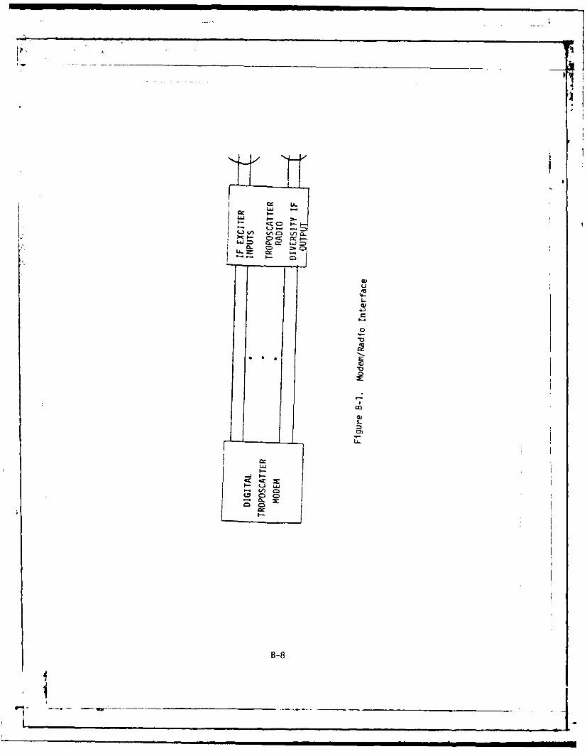
L LL
V)am
Lk.-
LLL
LAL
C66-
-8

3.2.1.3.1.3 SCBS Interface Requirements. When the SCBS of themodem is interconnected to an FCC-98, the BER at the 50 kb/sdata channel on output of the FCC-98 shall not be increased fromthat measured when the modem is configured as stated in 3.2.1.3.1.
3.2.1.3.2 Data and Clock Input/Output Signals. The modem shallprovide and accept the data and clock input/output signalsstated below and illustrated in Figures B-2a and B-2b.
a. Two MBS inputs with associated timing.b. Two MBS outputs with associated timing.c. One SCBS input with associated timing.d. One SCBS output with associated timing.e. Two MBS transmit clock outputs, phase locked
to the radio transmit clock.f. One SCBS transmit clock output, phase locked
to the radio transmit clock.g. One external clock input at the MBS rate
(Table B-Ill) of the radio internal multiplexers.h. One recovered receive timing output at the MBS
rate (Table B-Ill) of the modem internal TDMfunction.
3.2.1.3.3 Digital Inputj/Output Signal Characteristics. Thefollowing input/output signal characteristics shall apply toall data and timing inputs and outputs of the modem. The modemshall accept serial non-return-to-zero (NRZ) polar square wavedata with associated polar square wave (equal positive andnegative duration) timing at the mission and service channelinputs as shown in Figure B-3. The SCBS input will besynchronous with the modem transmit clock. The modem shallprovide NRZ data and timing at the mission and service channeloutputs. The modem shall accept polar square wave timingat the MBS rate (Table B-Ill) as the external clock input. Themodem shall provide polar square wave MBS and SCBS timingoutputs phase locked to the modem transmit clock at the MBSand SCBS bit rates, respectively.
3.2.1.3.3.1 Buffering. Buffering shall be included within the modemto interface with each incoming mission bit stream. Sufficientbuffer capacity shall be provided so that when the MBS source timingrate differs from the internal modem timing rate by as much as plusor minus 2 parts in x 10(6), the mean time to loss of bit countintegrity shall be at least 24 hours for each MBS. These buffersshall be arranged to automatically reset in the event of overflow orunderflow.
3.2.1.3.3.2 Output Characteristics
3.2.1.3.3.2.1 Impedance The output impedance for NRZ data andtiming shall be 78 ohms plus or minus 10 percent (balanced). Thecapacitive shunt shall be less than 15 picofarads to ground.
B-9
I __ _'

4c
cr0
-6 0 Li
- ~ B-10

414
I.l
-J-
C~Cs
CDC
x J0 z Y. 1 - - 2 a 1 I-
__L) 11 Z. L-~ ) i- 4 ~xC.) E . .) -
u )C m 0 )
Q 0
co C1CIIx 4.
LLC7

TIMING(SQUARE WAVE)
DATA +V1I0" 0
FULL WIDTHII ___
NRZ BINARYPULSEI
IL -V,
Figure B-3. Timing and NRZ Waveforms
B-12

J
3.2.1.3.3.2.2 Voltage Level. For the NRZ data and timing, apositive voltage is a logic one and a negative voltage is a logiczero. The open circuit voltage at the interface shall be plus orminus 4 volts, plus or minus 10 percent, and when terminated in itscharacteristic impedance, it shall be plus or minus 2 volts, plus orminus 10 percent.
3.2.1.3.3.2.3 Rise and Fall Time. The data and clock pulseoutput rise and fall times Tr and T(, in Figure B-4, when measuredbetween the 10 percent and 90 percent points shall be greaterthan 4 nanoseconds and less than 12 nanoseconds for data ratesgreater than 2 Mb/s, and shall be less than 100 nanoseconds fordata rates 2 Mb/s or less.
3.2.1.3.3.2.4 Data/Timing Relationships. The trailing edgepositive-to-negative transition of the output timing signal shalloccur within plus or minus 4 percent of the center of the nominalunit interval of the output NRZ data signal, as shown in Figure B-5.
3.2.1.3.3.2.5 Gu _t Jitte The output data and timing signalsshall not have more than plus or minus 4 percent jitter(peak-to-peak) of the nominal data unit interval.
3.2.1.3.3.3 Input Characteristics
3.2.1.3.3.3.1 Impedance. The input cable termination shall be 78ohms plus or minus 10 percent for NRZ data and timing inputs(balanced). The capacitive shunt shall be less than 15 picofarads toground.
3.2.1.3.3.3.2 Voltage Level. At the digital inputs, a voltage levelfrom plus or minus 0.2 volt to plus or minus 7.0 volts shall becorrectly detected and processed without adjustment. Voltage levelsup to and including plus or minus 14 volts shall not cause damage tothe modem.
3.2.1.3.3.3.3 Samplina Interval. At the digital input, NRZdata and timing signals shall be detected and processed at thezero crossing of the positive-to-negative transition of the timingsignal occurring within 25 percent of the center of the nominaldata unit interval of the NRZ data as indicated in Figure B-6.
3.2.1.3.3.3.4 Combined Effects of Jitter. The modem shalloperate properly with digital NRZ data and timing inputs, eachhaving jitter equal to as much as 12.5 percent of data unitinterval or a peak timing to peak data excursion of 25percent of the data unit interval.
3.2.1.3.5 Mission Bit Stream (MBS) Rate. The modem shallaccept the rates specified in Table B-Ill as input and providethese rates as output at the MBS Inputs/outputs.
B-13
-- .- -- Lt

*it
w 44
>J
00
I j0
- V
00
0B 1

II -V
, l I I I I I I IIiil
-4.4I.-4% OF-.
r7r
+V
DATA 0
AI ANOMINAL UNIT2
INTERVAL
Figure B-5. Phasing (Data & Tining RelationshipsTrailing Edge)
B-1 5
l AF- I-_ _
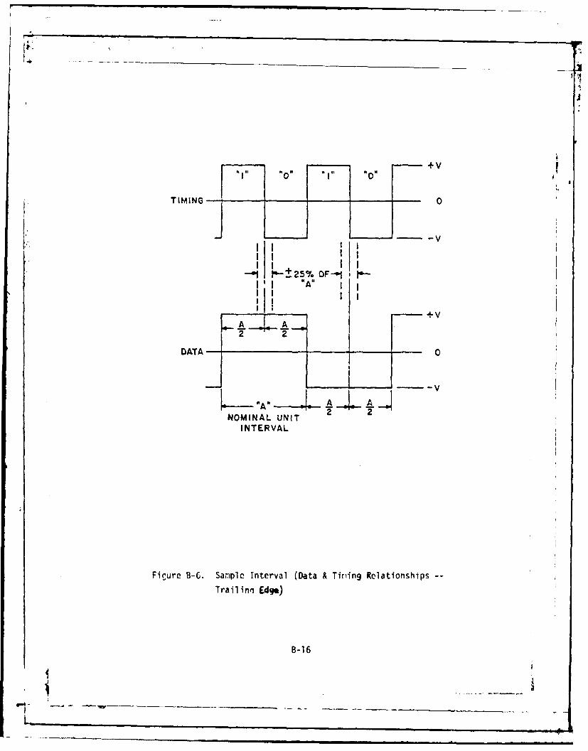
I "l" "0 "I" "0
-V
I I IIlII I I
" I I I
- -25% OF--1I I "A" I I
I I I I
A A
2 2
DATA 0
NOMINAL UNIT
INTERVAL
Fiure B-C. Sample Interval (Data & Tiriing Relationships --
Trailinn Edge)
B-16

3.2.1.3.6 Parallel Data. The modem shall provide and accepttwo synchronous MBS's at equal rates of 3.232 Mb/s and 6.464 Mb/s.These two data streams will be synchronously combined with theservice channel bit stream.
TABLE B-Ill. MISSION BIT STREAM RATES
Nominal MBS Nominal Data TimingRate Unit Interval Frequency(Mb/s) (msec) (MHz)
3.232 0.3094 3.232
6.464 0.1547 6.4649.696 0.1031 9.696
12.928 0.0774 12.928
3.2.1.3.7 Service Channel Bit Stream (SCBS) Rate. The modemshall accept as input and provide as output an SCBS of nominally192 kb/s. The SCBS operation will not be dependent on thepresence of the MBS. The modem shall provide transmit clockand receive timing signals for the SCBS (see Figure B-2). Thetiming signals shall meet the input/output signalcharacteristics of 3.2.1.3.3.
3.2.1.3.8 Protection. The modem shall provide the followinglevels of protection.
3.2.1.3.8.1 Lockup Protection. The operation of the modem shallbe such that when a 25 volt pulse as described below isapplied simultaneously to any combination of input/output leads,no logic lockup shall occur that results in service outage ordegraded performance requiring manual intervention to restoreservice. The rise time of the voltage pulse shall be 0.5volts/ nanoseconds with a duration of 1 microsecond between the50 percent amplitude points.
3.2.1.3.8.2 Interface Protection. Interface protection shallbe provided to the extent specified in MIL-STD-188-100,paragraph 4.3.1.3.3.9, Protection, elements (a) through.(d).
3.2.1.4 Internal Time Division Multiplex (TDMI. For thepurpose of multiplexing the one or two input mission bitstreams and the SCBS, the radio shall contain a synchronousTDM.
3.2.1.4.1 Synchronization Acouisition Time. At a Mean E4,/N0corresponding to a bit error rate of 1 part in 10(2), the modeminternal TDM shall acquire synchronization 90 percent of thetime within 50 milliseconds after application of the signal tothe IF interface point (3.1.4).
B-17
1-..

3.2.1.4.2 Mean Time to Loss of Synchronization. At a mean E&/Nocorresponding to a bit error rate of 1 part in 10(-2), the mean timeto declaration of loss of synchronization of the modem internal TOMshall be not less than 24 hours. An external multiplexer framesearch inhibit command signal shall be provided as an output of themodem. This signal shall inhibit the PCM and TDM multiplexer(s)interfaced with the modem from unnecessary reframe searches wheneither (a) the modem is in its frame reacquire (loss of BCI) mode, or(b) when the modem inhibits its own internal TOM frame search due toa low received S/N level (< 4 dB) or (c) when both conditions occur.The command signal shall be a transistor-transistor-logic (TTL) levelavailable at a connector on the modem. The TTL signal shall benormally a logic one (high) when conditions a, b or c above are notpresent and shall be a logic zero (low) when conditions a, b or c arepresent, to inhibit multiplexer frame searches. The TTL commandsignal shall have a minimum fan-out capability for driving up to eightTTL loads.
3.2.1.4.3 Bit Count Integrity (BCI). The internal TOM shall detecta loss of BC! and reacquire synchronization within 50 millisecondsfor 90 percent of the time at a mean EA/No corresponding to a 10(-6)bit error rate, provided the receive data and TOM were within plus orminus 2 bits of synchronism.
3.2.1.5 Timing. The transmit clock shall be provided by aninternal master oscillator providing performance as specified in3.2.1.5.1, 3.2.1.5.2, and 3.2.1.5.3. In addition, the modem shalloperate from an external source as specified in 3.2.1.5.4 andprovide recovered receive timing as specified in 3.2.1.5.5.
3.2.1.5.1 Initial Accuracy. One hour after the modem is energizedand at room ambient temperature (25*plus or minus 5* C), thefrequency of the timing output shall be within plus or minus 3 partsin 10(6) of the nominal values specified in Table B-III.
3.2.1.5.2 Environmental Stability. The frequency of the timingoutput.(Table B-III) of the internal TOM when subjected to the fulloperating temperature range specified in 3.3.10 shall not deviatemore than plus or minus 10 parts in 10(6) at 25*plus or minus 5*C.
3.2.1.5.3 Long Term Stability. The frequency of the timing output(Table B III) of the internal TOM shall not deviate more than plus orminus 1 part in 10(6) per month when repeated readings are taken atany single stable temperature (within plus or minus 20 C) with herange of operating temperatures specified in 3.3.10.
3.2.1.5.4 External Clock Source. The modem shall also operatefrom an external clock source of 5 MHz. The timing signal shall be aSINUSOID wave at a level of OdBm + or - 3 dB. The stability andaccuracy of the external clock source shall be + or - 1 art in 10•In the event the external source is lost, the modem shallautomatically switch to the internal oscillator.
B-18

VL
3.2.1.5.5 Receive Timing Output. Provisions shall be included inthe modem to provide recovered receive timing as an output througha connector and shall meet the square wave timing requirementsof 3.2.1.3.
3.2.2 Modulation Function
3.2.2.1 Transmitted Bandwidth Efficiency. When configured withany of the troposcatter radios listed in 3.2.1.3.1, the modemI. shall enable the transmitted bandwidth requirements as stated in3.2.1.2 of this specification to be met at the radio/antennainterface for each data rate/bandwidth combination specifiedtherein. The attenuation of the transmitted spectrum relativeto its maximum value measured in a 4 kHz band shall not be lessthan that given by the following relationship:
A = 35 + 0.8 (p-50) + 10 log B
where: A = attenuation in decibels below spectrum maxima.P = percent of transmitted bandwidth removed from the
authorized frequency.B = transmitted bandwidth in MHz.
3.2.2.2 Randomizing the Radiated Signal. The modulator functionshall provide for the randomizing of the transmitted spectrum toreduce the intensity of discrete spectral components in thetransmitted spectrum. The randomizer shall be of the selfsynchronizing type, contain a minimum of 20 stages, and shall meetperformance requirements specified in Table B-IV. A strappingfeature shall be provided to bypass the randomizer.
3.2.3 Demodulation Function
3.2.3.1 Modem Small Sional Performance. As a minimum, the modemshall provide the dual and quad diversity small signal performancestated in Table B-IV at the specified performance levels, for theMBS rate/transmitted bandwidth combinations delineated inparagraph 3.2.1.2 of this specification at rms fade rates of 0.01to 10 Hz, inclusive.
B11
i B-19

TABLE B-IV. MODEM SMALL SIGNAL PERFORMANCE
Maximum Mean F,6/ Nofor Profile
Performance Level P1 P2 P3 P4
I 2.0 20.5 1.5 18.0 1.5 18.5 2.0 18.51! 3.5 21.0 3.0 19.5 3.0 20.5 3.0 20.0
BER* 3E(-2)3E(-8) 3E(-2) 3E(-8) 3E(-2) 3E(-8) 3E(-2) 3E(-8)
~I (a) Quad Diversity
Maximum Mean E /N for Profile
Performance Level PI P2 P3 P4
r T.0 Z6.0 6.0 22.0 6.0 20.0 7.0 18.0II 10.0 28.0 9.0 26.0 9.0 24.0 9.0 25.0
BER* 3E(-2) 3E(-8) 3E(-2) 3E(-8) 3E(-2) 3E(-8) 3E(-2) 3E(-8)
(b) Dual Diversity
* with randomizer (3.2.2.2)
3.2.3.2 Radio Degradation. When configured with any of theradios listed in 3.2.1.3.1, the performance provided by themodem shall not be degraded beyond 2 dB from the values listedin Table B-IV when the radios are operated at their maximumattainable output RF power.
3.2.3.3 Aircraft Fading. The modem shall suffer no transientor steady state degradation in performance when exposed to rapidfading characteristic or aircraft reflections in the vicinityof the transhorizon propagation path.
3.2.3.4 Modem Dynamic Range , The modem dynamic range is thedifference in dB between the mean E4/N. determined in 3.2.3.1above for a quad diversity 3 x 10(-8) BER and mean E4N, above thelevel where the quad diversity BER becomes degraded from 3 x 10(-8).This dynamic range shall be a minimum of 50 dB for all profilesof Table B-I.
3.2.3.5 Modem BER Performance Floor. For a mean E4/N. O dBabove the E4/N, values determined in 3.2.3.1 for quad diversity,the BER shall not exceed 1 error in 10(9) bits 95 percent of thetime.
3.2.3.6 Frequency Stability. The nodem 70 MHz local oscillatorfrequency shall remain constant within 5 parts in 10(6) over any60-day period. This requirement shall be met beginning within 1hour of the initial application of power under all operating andenvironmental conditions specified herein..
B-20
..... ...__ _ _ _ _ _ _ _ _ _ _ _ _
- - - -_ _ __ __ _

3.2.3.7 Intermodulation. With any two equal level signals outsidethe authorized bandwidth applied to the modem IF interface point(3.1.4) at a level of -40 dBm, the level of third orderintermodulation products in the IF at a fixed gain shall not exceedthe signal level in the IF that would result from a single in-band-90 dBm signal applied to the IF interface point (3.1.4).
3.2.3.8 Adjacent (Non-Contiguous) Channel Interference. The modemshall meet performance requirements specified herein with aninterfering signal applied to the IF interface point (3.1.4)50 dB above the desired signal at a frequency separation of twicethe authorized bandwidth (Table B-Il) or greater from theassigned frequency.
3.2.3.9 Cn-channel Interference. The modem shall provide theperformance specified in Table B-IV with less than 2 dB degradationreceiver threshold, for interference of any type within thespecified modem passband having the following levels with respectto the desired signal:
a. Minus 20 dB for performance Level I.b. Minus 25 dB for performance Level I.
3.2.3.10 Carrier and Clock Recovery. The modem, when operating inquad diversity at a mean 4/N, corresponding to a BER of 1 error in10(2) bits, shall provide carrier and clock-recovery within 1.0millisecond. Once carrier recovery and bit synchronization have beenachieved, BCI and bit synchronization shall be maintained for notless than one minute when the input mean EA/No is reduced by 25 dBbelow the mean Ee/N& specified in 3.2.3.1 for a BER of 3 parts in10(8).
3.2.3.11 Spurious Response and Image Rejection. The modem IF inputcircuit selectivity characteristics from the combination of filtersand tuned circuits shall be such that all signals which are at orgreater than 70 MHz away from the IF center frequency shall be downmore than 80 dB with respect to the desired signal frequency asmeasured at the output of the IF.
3.2.4 Monitoring and Alarm (Visible and Remote). The modem shallinclude circuitry to monitor functions and provide an alarm in theevent of any failure listed below as a minimum. The alarm functionshall include: (1) 1 amp contact closures (form C) for remoting toexternal alarm monitoring circuitry and, (2) illumination of visiblealarm indicator on the front of the equipment for each failure. Thefollowing functions shall be monitored and alarmed.
3.2.4.1 Data Timing Inout/Output. All inputs and outputs shallbe monitored for loss of data or timing (3.2.1.3.2) (no transitionsfor 10 msec or more.) The alarm for one MBS or timing input/outputshall be disabled when only one MBS or timing input/output isbeing used.
B-21
...4 -- -- " . -~s inn~-. .. 7 1 21 _ ___

L
3.2.4.2 Modulator Output. Each modulator shall be monitored forloss of data activity (no transitions for 10 msec or more) andpower.
3.2.4.3 Demodulator Outout. Each demodulator output shall bemonitored for loss of activity (no transitions for 10 msec ormore).
3.2.4.4 .ndm FraF. The internal TDM function shall bemonitored for loss of receive frame synchronization.
3.2.4.5 Modulator Frequency Drift. An alarm inc '')n shall beproduced by the modem whenever the average transmi ,F frequencydeviates more than 2 percent of the transmitted bandwidth(3.2.1.2).
3.2.4.6 Power Supply. A visible indicator shall be provided toindicate that primary power has been applied. In the eventprimary power is lost or the protective device fails, theindicator shall be extinguished.
3.2.4.7 Modulator Output Power. Each modulator IF output shallbe monitored for a decrease in IF output power of 3 dB or morerelative to the selected output power between 0 and 20 dBm.
3.2.4.8 I e An alarm shall be provided which indicates
that any diversity IF input is at or above the saturation levelof the modem IF circuitry or below the minimum level requiredfor satisfactory operation as defined in 3.2.3.1.
3.2.4.9 Frame Error ThreshohP An alarm shall be providedwhich indicates when the error rate of framing bits exceeds1 error in 10(4) Bits.
3.2.5 Performance Monitors. Test points shall be provided atthe interface terminals for monitoring the following.
3.2.5.1 IF Rpcpiyed Signal Level. A signal shall be provided whichis linearly proportional to the RSL measured at the IF interface indBm. The monitor shall have a linear (+3 dB) range from 1 dB belowto 50 dB above the RSL derived in 3.2.3.1 for the specified bitrates. The sensitivity shall be at least 0.1 volt per dB change inRSL.
3.2.5.2 Frame Bit Error Rate. The framing bits in the modem shallbe monitored for errors. A pulse shall be provided at a connectoc onthe modem when one or more frame errors occur. The source impedance tshall be 75 ohms plus or minus 10 percent, unbalanced. The signalshall be 1 volt plus or minus 10 percent square pulses with nominalpulse duration equal to the data unit interval of the aggregate rate.
B-22
Ii

3.2.5.3 Signal Oualitv Monitor. The modem shall monitor
degradation of the received demodulated signal (eye pattern)
prior to data recovery and shall have an output voltage that is
monotonically related to the signal-to-noise ratio of the
demodulated signal. This relationship shall hold for a mean
E, Nof 20 dB to the mean Ed1N. corresponding to a BER of
xlO(-1). In addition to the signal quality monitor output,
buffered outputs shall be provided for each of the individual
eye patterns.
3.2.6 Mean Time Between Outage. The modem shall have a Mean
Time Between Outage of 100,000 hours where an outage is defined
as a reduction of performance to less than that required herein
for dual diversity operation.
7 B-23 i
I I I I I IIII
-
I1Li l l lll

DISTRIBUTION LIST
STANDARD:
R100 - 2 R200 - 25R1O2/RIO3/RlO3R - I R300 - IR102M - 1 R400 - 1R102T - 9 (8 fur stock) R500 - 1R104 -1 R700 - IR1O -I R800 - IR123 - I (Library) NCS-TS - IR124A - 1 (for Archives) 101A - 1
312 - 1
RIO2T - 12
DCA-EUR - 2 (Defense Communications Agency European AreaATTN: Technical DirectorAPO New York 09131)
DCA-PAC - 3 (CommanderDefense Communications Agency Pacific AreaWheeler AFB, HI 96854)
DCA SW PAC - I (Commander, DCA - Southwest Pacific RegionAPO San Francisco 96274)
DCA NW PAC - 1 (Commander, DCA - Northwest Pacific RegionAPO San Francisco 96328)
DCA KOREA - 1 (Chief, DCA - Korea Field OfficeAPO San Francisco 96301)
DCA-Okinawa - 1 (Chief, DCA - Okinawa Field OfficeFPO Seattle 98773)
DCA-Guam - 1 (Chief, DCA - Guam Field OfficeBox 141 NAVCAMS WESTPACFPO San Francisco 96630)
US NAV Shore EE PAC - I (U.S. Naval Shore Electronics EngineeringActivity Pacific, Box 130, ATTN: Code 420Pearl Harbor, HI 96860)
1843 EE SQ - 1 (1843 EE Squadron, ATTN: EIEXMHickam AFB, HI 96853)
DCA FO ITALY - 1 (DCA Field Office Italy, Box 166AFSOUTH (NATO), FPO New York 09524
,~
'i _ __ __

DISTRIBUTION LIST (cont'd)
USDCFO - 1 (Unclassified/Unlimited Distribution)(Chief, USDCFO/US NATOAPO New York 90667)
SPECIAL:
DCA -1 Code 470DCA - 1 Code 513
DCA Athens - 1 (Chief, DCA Field Office AthensAPO New York 09223)
HQ USAFATTN: RDSSWashington, DC 20330
Commander, USAF EuropeATTN: DCR
DCODOYLG
APO New York 09633Commander
Rome Air Development CenterATTN: DCCGriffiss AFB, NY 13442
CommanderElectronic Systems Division (AFSC)ATTN: DCF-I
DCJWE
Hanscom Field, MA 01730
CommanderAir Force Communications CommandATTN: EPPD
LGMKR1842EEG
Scott AFB, IL 62225
Commander, NCAATTN: EIEGMGriffiss AFB, NY 13442
_
_ _ __

ii
Commander in ChiefEuropean CommandATTN: ECJ-6
PPPF
APO New York 09128
Commander, ADCOMATTN: XPPeterson AFB, CO 80914
CommanderEuropean Communications Area (AFCC)ATTN: LGMAPO New York 09633
CommanderSacramento Air Logistics CenterATTN: MMCREA/Mr, J. FlattSacramento, CA 95652
Commander, USACSAATTN: CCM-RD
CCM-TS-CFt. Monmouth, NJ 07703
Commander, USACCATTN: CC-OPS-SR
CC-OPS-STFt. Huachuca, AZ 85613
Commander, USACEEIAATTN: CCC-CED-XEMFt. Huachuca, AZ 85613
Commander, USACORADCOMATTN; DRDCO-COM-RM-3Ft. Monmouth, NJ 07703
CommanderNaval Telecommunications CommandATTN: Code 621A
4401 Massachusetts AvenueWashington, DC 20390
National Security AgencyATTN: S03Ft. Meade, MD 20755
Director* Joint Tactical Communications
ATTN; TT-E-EX (TRI-TAC) OfficeFt. Monmouth, NJ 07703
I .. .. 0

[II
U.S. Department of CommerceInstitute for Telecommunications ScienceATTN: Mr. W. HubbardBoulder, CO 80303
Electromagnetic Compatibility Analysis CenterNorth SevernATTN: CJAnnapolis, MD 21402
_ _ _ _
-I~- -- ~- _ _ _ _ _ _ _