Embed Size (px)
Citation preview

Surgical Technique gu ide
A less-invasive surgical option for pedicle screw placement.
NX SyStemAnyPlus®
g S M e d i c l e u S a . c o m

MiniMally invasive spine surgery has several advantages over traditional open techniques. sMaller incisions and MiniMal Muscle dissection can Markedly decrease blood loss and postoperative pain.
the anyplus® nX systeM was created to offer a less invasive surgical option for pedicle screw placeMent. the systeM incorporates anatoMically driven solutions such as self-tapping cannulated polyaXial screws and pre-lordosed rods. the instruMentation is ergonoMically designed to allow for either a true percutaneous or Wiltse approach. the anyplus® nX systeM offers a siMple, precise and efficient solution to spinal fiXation.
This is intended as a guide only. There are multiple techniques for the insertion of pedicle screws and, as with any surgical procedure, a surgeon should be thoroughly trained before proceeding. Each surgeon must consider the particular needs of each patient and make the appropriate adjustments when necessary and as required. Please refer to the Instructions for Use insert for complete system description, indications and warnings.
intended useWhen used as a posterior, non-cervical pedicle screw system, the AnyPlus® NX screw system is intended to provide immobilization and stabilization of spinal segments in skeletally mature patients as an adjunct to fusion in the treatment of the following acute and chronic disorders of the thoracic, lumbar and sacral spine:• Degenerativediscdisease(DDD)asdefined
bybackpainofdiscogenicoriginwithdegenerationofthediscconfirmedbypatienthistoryandradiographicstudies
• Degenerativespondylolisthesis
• Trauma(i.e.,fractureordislocation)
• Spinalstenosis
• Deformitiesorcurvatures(i.e.,scoliosis,hyper-kyphosisorhypo-kyphosis)
• Tumor
• Pseudoarthrosis
preoperative planningWhen using the AnyPlus® NX Screw System, the patient should be positioned prone on a radiolucent table, custom radioluscent frames are ideal, chest rolls may be used, but the knee-to-chest position should be avoided.
Using fluoroscopic imaging, it should be verified that the true views of both anterior-posterior (A/P) and lateral images of the spine (views which adequately delineate pedicle morphology and geometry) are obtainable. It is also recommended that preoperative planning be used to help determine a proper entry point and trajectory.
After identifying the pedicle entry point, a targeting needle and guide should be used to initiate the starting entry point. Adjustments to the entry angle and the trajectory should be made as often as needed with the assistance of fluoroscopic imaging until the proper position is attained.
NX SyStemAnyPlus®

gs Medical 1
table of contents
intended use
preoperative planning
surgical technique steps
step: 1 pedicle targeting &
guidewire placement ..................................... 2
step: 2 tissue dilation & tapping ........................ 3
step: 3 screw tower & driver assembly .............. 5
step: 4 screw insertion ........................................ 7
step: 5 rod Measurements ................................. 8
step: 6 tissue preparation ................................... 9
step: 7 rod insertion ......................................... 10
step: 8 rod reduction ...................................... 12
step: 9 compression & distraction ................... 14
step: 10 final tightening ................................... 16
step: 11 tower removal .................................... 17
product catalog and ordering information
anyplus® implants ........................................... 18
instruments ....................................................... 19
instrument cleaning, care
and handling policies ................................. 22
important information on
the anyplus® nX spinal system .................. 23
NX SyStemAnyPlus®

2 gs Medical
pedicle targeting & guidewire placementSTEP 1It is recommended that preoperative planning be used to help determine the proper entry point and trajectory as the starting point is not usually at the point directly over the pedicle.
Identify the operative levels using A/P and lateral fluoroscopy. Plan the entry point to target the pedicle from a transverse trajectory lateral to the facet.
Make an incision through the skin and fascia. The typical starting point is 3-4cm off the midline.
Insert the targeting needle and guide down to the surface of the pedicle, dock the tip on the bony anatomy of the desired level and confirm placement with A/P fluoroscopy. Adjustments to the entry angle and the trajectory should be made until the proper position is attained.
Advance the targeting needle and guide down through the pedicle. Once proper placement is confirmed, remove the inner stylet of the targeting needle.
Insert the guidewire through the cannulated targeting needle sheath and advance the guidewire just past the tip of the targeting guide. Use caution when advancing the guidewire under fluoroscopy to ensure the location of the guidewire. Once the guidewire is in place, remove the targeting needle and leave the guidewire in place.
Instrumentsused:KWirebluntandTargetingNeedle(shownleft)
3-4cm
TargetNeedlePositioning
1

gs Medical 3
STEP 2A longitudinal incision of about 1.5cm is made through the skin and fascia. An incision of 1.5cm will facilitate the insertion of the towers used later in the procedure.
Caution: Use fluoroscopy to monitor guidewire advancement during dilation.
Prepare a pathway to the pedicle by sequentially using dilators 1,2 and 3. Once the dilator 3 is placed remove the inner dilators and place them over the adjacent guidewire. Leave the dilator 3 in place to protect the soft tissue while tapping.
tissue dilation & tapping 2
1
2
3
enhanced Grip
Facilitates Advancement
Instrumentsused:BluntGuidewire,SharpGuideWire,
Dilator1,Dilator2,Dilator3
dila
Tor 1: #u
S114-9003
dila
Tor 2: #u
S114-9004
dila
Tor 3: #u
S114-9005
Sha
rp gu
ide W
ire .063x18.5 #u
S114-0111
Blun
T gu
ide W
ire .063x18.5 #u
S114-0110

4 gs Medical
tissue dilation & tapping 2continued
STEP 2Caution: Use fluoroscopy to monitor guidewire advancement during tapping.
Attach the appropriate tap size to the preferred handle (axial or T). Place the tap over the guidewire and through dilator 3 to the surface of the pedicle. The depth markers on the tap shaft where the tap shaft meets the top of the large dilator are used to monitor insertion. They can also be used to determine screw length.
Note: insert saline to inner cannula of tap prior to advancing it down the guide wire to prevent further advancement of the guidewire.
Once desired depth has been achieved remove tap while maintaining control of guidewire.
Load the eMg sleeve over dilator 3 and advance to bony anatomy. Depth can be verified by using fluroscapy to locate the ring at the distal tip of the eMg sleeve.
Instrumentsused:Tap,Dilator3,EMGSleeve,RatchetingT-Handle
eMg
Sleeve #u
S114-9006
dila
Tor 3: #u
S114-9005
Tap 5.5M
M #u
S114-9055
Tap 6.5M
M #u
S114-9065
Tap 7.5M
M #u
S114-9075
Tap 8.5M
M #u
S114-9085
raTc
heTin
g T-h
an
dle
#uS110-1002

gs Medical 5
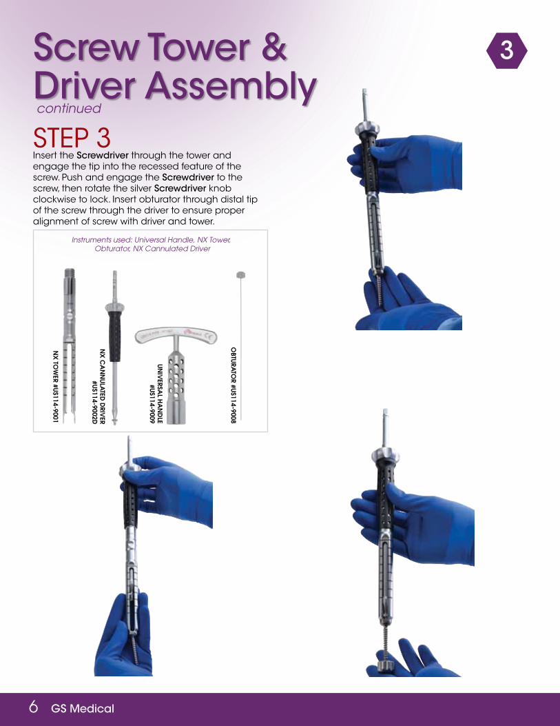
screw tower & driver assembly
3
STEP 3tower assembly – Verify that the tower tangs are fully extended. Carefully engage the polyaxial screw head to the tangs on the distal end of the tower ensuring that the tangs match the holes on the screw and slide sleeve down till the tangs are fully retracted into the tower. Next, affix torque handle across Tower and secure the universal handle to the proximal end. Finally, apply counter pressure to fully tighten screw onto tower.
To verify that the screw is fully locked, ensure that the screw cannot be dislodged by pulling it away or rotating it.
6 gs Medical
Instrumentsused:UniversalHandle,NXTower,Obturator,NXCannulatedDriver
3
STEP 3 Insert the screwdriver through the tower and engage the tip into the recessed feature of the screw. Push and engage the screwdriver to the screw, then rotate the silver screwdriver knob clockwise to lock. Insert obturator through distal tip of the screw through the driver to ensure proper alignment of screw with driver and tower.
screw tower & driver assemblycontinued
un
iverSa
l ha
nd
le #u
S114-9009
nx
ToW
er #uS114-9001
nx
ca
nn
ula
Ted d
river
#uS114-9002d
oBTu
raTo
r #uS114-9008

gs Medical 7
screw insertion 4
STEP 4 Attach the preferred handle to the screwdriver. Guide the tower and polyaxial screwdriver assembly over the guidewire and into the pedicle. Advance the screw to the desired depth and verify placement under fluoroscopy. After screw placement, remove the guidewire and Screwdriver from the tower. Turn
the silver knob of the polyaxial screwdriver counter-clockwise and gently tug in an upward motion to remove the Screwdriver Assembly from the tower.
Repeat the steps above to place the second polyaxial screw at the adjacent operable level.
InstrumentsUsed:K-Wire,EMGSleeve,NXTower,NXCannulatedDriver,RatchetingT-Handle
to Release
eMg
Sleeve #u
S114-9006
nx
ToW
er #uS114-9001
nx
ca
nn
ula
Ted d
river
#uS114-9002d
raTc
heTin
g T-h
an
dle #u
S110-1002

8 gs Medical
InstrumentsUsed:NXTower,RodLengthGauge
5rod MeasurementsSTEP 5 To prepare for rod insertion ensure all of the screws and tower slot openings are in the longitudinal plane. Next,to measure for appropriate rod length, insert the rod gauge to the proximal end of the towers.
Based on the screw positions, the pointer will indicate the appropriate rod length on the Gauge. Read rod measurement length from size marking on caliper. If the pointer falls between measurements, the measurement should be rounded up to the next rod length. After determining the rod length, remove the rod gauge.
rod lengTh gauge
#uS114-9011
nx
ToW
er #uS114-9001

gs Medical 9
InstrumentsUsed:WandingBlade,NXTower
6tissue preparationSTEP 6 The AnyPlus Wanding blade may be used to dissect interfering tissue to assist in rod placement.
nx
ToW
er #uS114-9001
Wa
nd
ing
Blad
e #uS114-9010
10 gs Medical
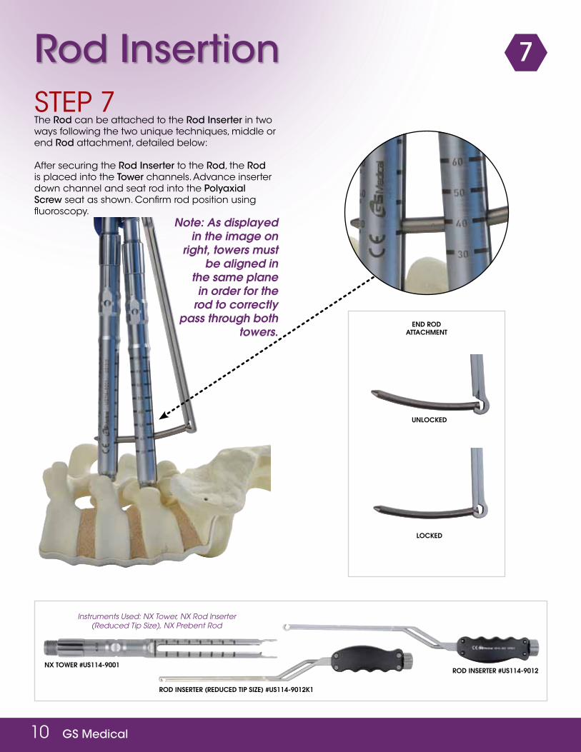
7rod insertion
end rod aTTachMenT
unlocked
locked
STEP 7 The rod can be attached to the rod inserter in two ways following the two unique techniques, middle or end rod attachment, detailed below:
After securing the rod inserter to the rod, the rod is placed into the tower channels. Advance inserter down channel and seat rod into the polyaxial screw seat as shown. Confirm rod position using fluoroscopy.
InstrumentsUsed:NXTower,NXRodInserter(ReducedTipSize),NXPrebentRod
nx ToWer #uS114-9001
rod inSerTer (reduced Tip Size) #uS114-9012k1
rod inSerTer #uS114-9012
Note: As displayed in the image on
right, towers must be aligned in
the same plane in order for the
rod to correctly pass through both
towers.

gs Medical 11
7rod insertioncontinued
For delivery between the towers, align the towers as shown and position the rod ends in the rod channels of the towers. Advance the rod into the polyaxial screw tulip head and confirm rod position using fluoroscopy.
Middle rod aTTachMenT
unlocked
locked
InstrumentsUsed:NXTower,NXRodInserter(ReducedTipSize),NXPrebentRod
nx ToWer #uS114-9001
rod inSerTer (reduced Tip Size) #uS114-9012k1
rod inSerTer #uS114-9012

12 gs Medical
8rod reductionSTEP 8 Load Set Screw from caddy onto rod reducer t-handle. Insert loaded starter through tower shaft and thread into the tulip head of the pedicle screw.
To reduce rod turn silver handle of rod reducer t-handle clockwise to fully engage rod into the tulip head.
reducTion needed
Once Set Screws are provisionally tightened, release and remove rod inserter and rod reducer t- handle.

gs Medical 13
8rod reductioncontinued
InstrumentsUsed:Rodinserter,NXtower,UniversalHandle,SetScrewDriver/RodReducer,SetScrewStarter
If rod reduction is necessary, the AnyPlus® NX rod reduction sheaths can assist in obtaining full reduction of the rod into the tulip head of the pedicle screw. Slide reduction sheaths over the NX towers at each level.
Next, attach the universal handle to the reduction sheath tower and turn the handle clockwise at each level until the desired reduction has been achieved.
reduced
nx
ToW
er #uS114-9001
rod
inSerTer #u
S114-9012
SeT ScreW
driv
er/ro
d red
uc
er #u
S114-9015
un
iverSa
l ha
nd
le #u
S114-9009
SeT ScreW
STarTer #g
S110-2318

14 gs Medical
InstrumentsUsed:NXtower,Compression/Distractiondevice,Compression/Distractionhandle
9compression & distraction
Compression Option 1
nx ToWer #uS114-9001
alTernaTe coMpreSSion/diSTracTion device #gS114-1510
STEP 9 The compression/distraction external tool will allow you to compress or distract at the operative level while maintaining position at the adjacent level.
Attach the fulcrum arm to the compression/distraction external device. There are two separate instruments that accomplish this step depending on surgeon preference.
Place the compression/distraction tool between the towers.
for compression: After provisionally tightening the set screw on the stationary level; place the levers with the rotatable hinges on the lower indent on the tower. The fulcrum arm should be angled upward. Compress to the desired amount for the construct.
for distraction: After provisionally tightening the set screw on the stationary level; place the levers with the rotatable hinges on the lower indent of the tower. The fulcrum arm should be angled downward. Distract to the desired amount for the construct.
Note: once desired compression/distraction is gained tighten the mobile tower provisionally and proceed with final tightening.
Distraction Option 1

gs Medical 15
9compression & distraction continued
InstrumentsUsed:NXtower,Compression/Distractiondevice,Compression/Distractionhandle
The compression/distraction tool will allow the surgeon to compress or distract the operable level and maintain position.
Place the compression/distraction tool between the towers.
Compression Option 2
Distraction Option 2
for compression: Attach the tool with the bar below the pivot point.
Provisionally tighten one of the set screws and then compress by rotating the butterfly knob.
for distraction: Attach the tool with the bar above the pivot point.
nx ToWer #uS114-9001
coMpreSSion/diSTracTion handle #uS114-9007
coMpreSSion/diSTracTion handle #uS114-9007

16 gs Medical
10final tighteningSTEP 10 Slide the torque stabilizer across the two towers engaging the slots as the tool advances.
Assemble the 12 Nm toque handle with the set screw driver and guide it through the tower into the set screw.
Turn the torque handle clockwise. Final tightening is achieved when the torque handle and set screw driver audibly clicks.
Remove toque handle assembly and the torque stabilizer.
Instrumentsused:NXTower,
TorqueStabilizer,TorqueHandle
nx ToWer #uS114-9001
Torque STaBilizer
#uS114-9013
Torque handle
#uS114-9018

gs Medical 17
11tower removalSTEP 11 Caution: Confirm final tightening of all construct screws before removing the towers.
Gently turn the knob on the tower counterclockwise and pull sleeve. Rotate the tower 90° and remove from the surgical field.

18 gs Medical
anyplus® implantsproduct catalog and ordering inforMation
anyplus® poly cannulated screw 5.5mm catalog nuMber length (MM)0983-5535 350983-5540 400983-5545 450983-5550 500983-5555 55
anyplus® poly cannulated screw 6.5mmcatalog nuMber length (MM)0983-6535 350983-6540 400983-6545 450983-6550 500983-6555 55
anyplus® poly cannulated screw 7.5mmcatalog nuMber length (MM)0983-7535 350983-7540 400983-7545 450983-7550 500983-7555 55
anyplus® poly cannulated screw 8.5 catalog nuMber length (MM)0983-8540 400983-8545 450983-8550 500983-8555 55
anyplus® set screw 10.6mm x 4.7mmcatalog nuMber0954-0002
Mis nX rodcatalog nuMber length (MM)9251-0040 409251-0045 459251-0050 509251-0055 559251-0060 609251-0065 659251-0070 709251-0075 759251-0080 809251-0085 859251-0090 909251-0095 959251-0100 100*9251-0105 1059251-0110 110*9251-0115 1159251-0120 120*9251-0125 1259251-0130 130*9251-0135 1359251-0140 140*9251-0145 145*9251-0150 150*9251-0155 155*9251-0160 160*9251-0165 165*9251-0170 170*9251-0175 175*9251-0180 180*9251-0185 185*9251-0190 190*9251-0195 195
*indicates special order size/available upon request
nX straight rod 5.5mmcatalog nuMber length (MM)9256-0200 2009256-0210 2109256-0220 2209256-0230 2309256-0240 2409256-0250 2509256-0260 2609256-0270 2709256-0280 2809256-0290 2909256-0300 300

gs Medical 19
instruments
US114-9055 TAP 5.5mm
US114-9002D SCREW DRIVER
US114-9007 COMPRESSION/
DISTRACTION
US114-9065 TAP 6.5mm
US114-9003 DILATOR 1
US114-9008 OBTURATOR
US114-9075 TAP 7.5mm
US114-9004 DILATOR 2
US114-9009 UNIVERSAL HANDLE
US114-9085 TAP 8.5mm
US114-9005 DILATOR 3
US114-9010 WADING BLADE
US114-9001 TOWER
US114-9006 EMG SLEEVE
US114-9011 ROD GAUGE
20 gs Medical
instruments
US114-9012 ROD INSERTER
US114-9023 GUIDEWIRE DRIVER
US114-9013 TORQUE STABILIZER
US114-9019 CANNULATED AWL
US114-9012k1ROD INSERTER
(REDUCED TIP SIZE)
US114-9014 SET SCREW STARTER DRIVER
US114-3010 RATCHETING AXIAL HANDLE
US114-9012k1 ROD REDUCTION
SHEATH
US114-9015 ROD REDUCER T-DRIVER
US114-1002 RATCHETING T-HANDLE
US114-9022 SINGLE LEVEL TORQUE
STABILIZER
US114-9016 SET SCREW DRIVER
US114-9018 TORQUE HANDLE
GS110-2318 SET SCREW DRIVER
WITH T HANDLE
US114-9020 PALM HANDLE

gs Medical 21
instruments
GS110-2317 SET SCREW DRIVER
WITH STRAIGHT HANDLE
US114-9028 EXTERNAL REDUCER
TNL0815TARGETING GUIDE
US114-0110 BLUNT GUIDE WIRE
.063X18.5
US114-0111 SHARP GUIDE WIRE
.063X18.5

22 gs Medical
instrument cleaning, care and handling policiesoverviewSurgical instruments are supplied NON-STERILE, and must be sterilized before use. After each use, instruments must be properly cleaned, disinfected, sterilized and stored. The following information outlines the proper steps for reprocessing GS Medical surgical instruments.
cleaning accessorieswater - Cold deionized or reverse osmosis water should be used, as temperatures above 140°F (60°C) will coagulate proteins, rendering them difficult to remove from contaminated items.
detergent - Prepare detergent (i.e., LIQUI-NOX®, Alconox, Inc. 9.5 pH) per manufacturer recommendations, or typical hospital grade instrument detergent or soap.
Manual cleaning accessories - Brushes, Gloves, Absorbent Disposable Cloth (i.e., KIMWIPE®, Kimtech Science)
liMitations and restrictions of reprocessingSurgical instruments are designed for their durability and ability to reuse. GS Medical reusable instruments are typically manufactured from steel stainless steel, which permits a long life when handled and maintained properly. Repeated processing has minimal effect on these instruments. End of life is normally determined by wear and damage to use.
cleaning / disinfectingwarnings - When handling sharp instruments use extreme caution to avoid injury; consult with an infection control practitioner to develop and verify safety procedures for all levels of direct instrument contact.
Clean Instruments as soon as possible after use. Do not allow blood or debris to dry on the instruments. If cleaning must be delayed, place groups of instruments in a covered container with water or an appropriate detergent to delay drying. Clean all instruments whether or not they were used or inadvertently contacted blood or saline solution.
preparation for cleaning - The cleaning process must be conducted so that all parts of the surgical instrument are exposed as permitted by design. The cleaning process should include an individual who is properly gowned with appropriate glove and personal protective equipment. Items with lumens, cannulations, etc. must be carefully cleaned to remove all visible debris from the item.
Manual cleaning and disinfection Clean instruments to remove gross contamination and disinfect instruments to reduce the number of viable microorganisms. Rinse in warm water to remove any gross contamination. Wash with a detergent with a pH of 7.0 to 10.0. Scrub the components with a soft brush. Rinse thoroughly with warm running water. Dry the instrument with a clean, disposable, absorbent cloth. Visually inspect for cleanliness. All visible surfaces, internal and external, should be visibly inspected. If necessary, re-clean / disinfect the instrument until it is visibly clean.
autoMated cleaning and disinfectingAn automatic cleaning process may be used i.e. ultrasonic cleaner or other related type machine that cleans and decontaminates items provided their own unique instructions are followed. Be aware that loading patterns, instrument cassettes, and other external factors may change the effectiveness of the cleaning equipment.
inspection, Maintenance and testingSurgical instrument and instrument cases are susceptible to damage from prolonged use, and through misuse or rough handling. Care must be taken to avoid compromising their exact performance. To minimize damage, the following should be done. Inspect the instrument and cases for damage when received and after each use and cleaning. Incompletely cleaned instruments should be recleaned, and those that need repair set aside and returned to GS Medical or its distributor. Instruments and instrument cases must only be used for their intended purpose.
packagingThe GS Medical instrument case is intended to protect instrumentation during shipment. Any damage noted should be reported to GS Medical immediately. Damaged packaging may indicate the presence of unsafe product. If the product is damaged, the product should not be used and should be returned.
sterilizationGS Medical surgical instruments manufactured of stainless steel or titanium may be steam sterilized with no detrimental effects. Steam Sterilization Cycle instruments are supplied NON-STERILE and must be sterilized before use. The recommended sterilization process is high temperature steam autoclave sterilization. It is also recommended that the trays be double wrapped using two standard sterilization wraps.
validated cycle is: Method: Steam Cycle Pre-vacuum Temperature 270°F (132°)Exposure time: 4 minutesDrying Time: 20 minutes
storageSurgical instruments that will not be utilized within a short period of time and will not be immediately returned to GS Medical must be stored clean, decontaminated, and completely dry. The packaging that items are sterilized in may offer an effective barrier to prevent contamination. Instruments should be stored in a clean area until ready for use.
sterilizationAll instruments must be sterilized according to the instructions outlined in the packaged insert-Instructions For Use (IFU) unless otherwise provided sterile.
Method cycle temperature exposure timeSteam Pre-Vacuum 270oF (132oC) 4 MinutesSteam Gravity 250oF (121oC) 20 MinutesSteam Gravity 273oF (134oC) 20 Minutes
gs Medical 23
important information on the anyplus® nX spinal systempurposeThe AnyPlus® NX Spinal System is intended to help provide immobilization and stabilization segments as an adjunct to fusion of the thoracic, lumbar, and /or sacral spine.
descriptionThe AnyPlus® NX Spinal System consists of a variety and sizes of rods, screws, transverse links, as well as implant components which can be rigidly locked into a variety of configurations with each construct being tailor-made for the individual case.
AnyPlus® NX Spinal System implant components are made out of medical grade titanium alloy described by such standards as ASTM F67 or ASTM F136 or ISO 5832-3 or 5832-2. GS Medical warranties and merchantability and fitness for a particular purpose or use are specifically excluded. See the GSS Catalog for further information about warranties and limitations of liability.
Never use stainless steel and titanium implants in the same construct. To achieve the best result, do not use any of the AnyPlus® NX Spinal System implant components with components from any other system or manufacturer unless specifically allowed to do so in this or another GS Medical document. As with all orthopaedic and neurosurgical implants, none of the AnyPlus® NX Spinal System components should ever be reused under any circumstance.
indications, contraindications and possible adverse events.The AnyPlus® NX System is a non-cervical spinal fixation device intended for use as a posterior pedicle screw fixation system, a posterior non-pedicle screw fixation system, or as an anterolateral fixation system. Pedicle screw fixation is limited to skeletally mature patients. The device is indicated for all of the following indications regardless of the intended use. 1. Degenerative disc disease (DDD) as defined by back pain of
discogenic origin with degeneration of the disc confirmed by patient history and radiographic studies
2. Severe spondylolisthesis (Grades 3 and 4) of the L5-S1 vertebrae3. Degenerative spondylolisthesis4. Trauma (i.e., fracture or dislocation)5. Spinal stenosis6. Deformities or curvatures (i.e., scoliosis, kyphosis, and/or lordosis)7. Tumor8. Pseudoarthrosis
descriptionContraindications include, but are not limited to: 1. Failed previous fusion Active infectious process or significant risk of
infection (immunocomprise).2. Signs of local inflammation.3. Fever or leukocytosis.4. Mordid obesity5. Pregnancy6. Mental illness7. Grossly distorted anatomy caused by congenital abnormalities. 8. Any other medical or surgical condition which would preclude the
potential benefit of spinal implant surgery, such as the presence of congenital abnormalities, elevation of sedimentation rate unexplained by other diseases, elevation of white blood count(WBC), or a marked left shift in the WBC differential count.
9. Rapid joint diseases, bone absorption, osteopenia, osteomalacia and/or osteoporosis.
10. Suspected or documented metal allergy or intolerance.11. Any case not needing a bone graft and fusion.12. Any case where the implant components selected for use would be
too large or too small to achieve a successful result.13. Any case requires the mixing of metals from two different components
or system.14. Any patient giving inadequate tissue coverage over the operative site
or inadequate bone stock or quality. 15. Any patient which implant utilization would interfere with anatomical
structures or expected physiological performance. 16. Any patient unwilling to follow postoperative instruction.17. Any case not describe in the indications.
possible adverse eventsAll of the possible adverse events associated with spinal fusion surgery without instrumentation are possible. With instrumentation, a listing of potential adverse events includes, but is not limited to: 1. Early or late loosening of any or all of the components.2. Disassembly, bending, and/or breakage of any or all of the
components.3. Foreign body (allergic) reaction to implants, debris, corrosion products
(for, crevice, fretting, and/or general corrosion), including metallosis staining, tumor formation, and/or autoimmune disease.
4. Pressure on the skin from the component parts in patients with inadequate tissue coverage over the implant possibly causing skin penetration, irritation, fibrosis, necrosism, and/or pain. Bursitis. Tissue or neve damage caused by improper positioning and placement of implants or instrument.
5. Post-operative change in spinal curvature, loss of correction, height, and/or reduction.
6. Infection.7. Dural tears, pseudomeningocele, fistula, persistent cerebrospinal fluid
leakage, meningitis.8. Loss of neurological function (e.g, sensory and/or motor), including
paralysis (complete or incomplete), dysesthesias, hyperesthesia, anesthesia, paresthesia, appearance of radiculopathy, and/or the development or continuation of pain, numbness, neuroma, spasms, sensory loss, tingling sensation, and/or visual deficits.
9. Cauda equina syndrome, neuropathy, neurological deficits (transient or permanent), paraplegia, paraparesis, reflex deficits, irritation, arachnoiditis, and/or muscle loss.
10. Urinary retention or loss of bladder control or other types of urological system compromise.
11. Scar formation possibly causing neurological compromise or compression around nerves and/or pain.
12. Fracture, microfracture, resorption, damage, or penetration of any spinal bone (including the sacrum, pedicles, and/or vertebral body) and/or bone graft or bone graft harvest site at, above, and/or below the level of surgery. Retropulsed graft.
13. Herniated nucleus pulposus, disc disruption or degeneration at, above, or below the level of surgery
14. Non-union (or pseudarthrosis). Delayed union. Mal-union.15. Cessation of any potential growth of the operated portion of spine.16. Loss of or decrease in spinal mobility or function.17. Inability to perform the activities of daily living.18. Bone loss or decrease in bone density, possibly caused by stress
shielding.19. Graft donor site complications including pain, fracture, or wound
healing problems.20. Ileus, gastritis, bowel obstruction or loss of bowel control or other types
of gastrointestinal compromise.21. Hemorrhage, hematoma, occlusion, seroma, edema, hypertension,
embolism, stoke, excessive bleeding, phlebitis, wound necrosis, wound dehiscence, damage to blood vessels, or other types of cardiovascular system compromise.
22. Reproductive system compromise, including sterility, loss of consortium and sexual dysfunction.
23. Development of respiratory problems e.g. pulmonary embolism, atelectasis, bronchitis, pneumonia, etc.
24. Change in mental status.25. Death
Note:Additionalsurgerymaybenecessarytocorrectsomeofthesepotentialadverseevents.
warning and precautionsFederal law restricts this device to sale by or on the order of a licensed physician.
continued

24 gs Medical
important information on the anyplus® nX spinal system
continued
The safety and effectiveness of spinal systems have been established only for spinal conditions with significant mechanical instability or deformity requiring fusion with instrumentation. These conditions are significant mechanical instability or deformity of the sacral, lumbar, thoracic and cervical spine secondary to degenerative spondylolisthesis with objective evidence of neurological impairment, fracture, dislocation, scoliosis, kyphosis, spinal tumor and failed previous fusion (pseudoarthrosis).
Only experienced surgeons should perform the implantation of spinal systems with specific training in the use of this spinal system because this is a technically demanding procedure presenting a risk of serious injury to the patient.
Based on the fatigue testing results, the surgeon should consider the levels of implantation, patient weight, patient activity level, other patient conditions, etc. which may impact the performance of the system.
warning and precautionsAlthough the physician is the designated intermediary between the company and the patient, the important medical information given in this document should be conveyed to the patient.
CAUTION: NATIONAL LAW RESTRICTS THESE DEVICES FOR SALE By OR ON THE ORDER OF A PHySICIAN.
CAUTION: FOR USE OR By THE ORDER OF A PHySICIAN ONLy.
iMplant selectionThe selection of the proper size, shape and design of the implant for each patient is crucial to the success of the procedure. Metallic surgical implants are subject to repeated stresses in use, and their strength is limited by the need to adapt the design to the size and shape of human bones. Unless great care is taken in patient selection, proper placement of the implant, and postoperative management to minimize stresses on the implant, such stresses may cause metal fatigue and consequent breakage, bending or loosening of the device before the healing process is complete, which may result in further injury or the need to remove the device prematurely.
device fiXationFor self breaking plugs, always hold the assembly with the Counter Torque device. Tighten and break-off the head of the set screw to leave the assembly at optimum fixation security. After the upper part of the self breaking set screw has been sheared off, further re-tightening is not necessary and not recommended.
preoperative1. Only patients that meet the criteria described in the indications
should be selected.2. Patient conditions and/or predispositions such as those addressed in
the aforementioned contraindications should be avoided.3. Care should be used in the handling and storage of the implant
component. The implant should not be scratched or otherwise damaged. Implant and instruments should be protected during storage, especially from corrosive environments.
4. An adequate inventory of implants should be available at the time of surgery, normally a quantity in excess of what is expected to be used.
5. Since mechanical arts are involved, the surgeon should be familiar with the various components before using the equipment and should personally assemble the devices to verify that all parts and necessary instruments are present before the surgery begins. The GSS Spinal system components (described in the DESCRIPTION section) are not to be combined with the components from another manufacturer. Different metal types should never be used together.
6. All components and instruments should be cleaned and sterilized before use. Additional sterile components should be available in case of an unexpected need.
intraoperative1. Only patients that meet the criteria described in the indications
should be selected. 2. Extreme caution should be used around the spinal cord and nerve
roots. Damage to the nerves may cause loss of neurological functions.3. Breakage, slippage, or misuse of instruments or implant components
may cause injury to the patient or operative personnel.4. The rods should not be repeatedly or excessively bent. The rods should
not be reverse bent in the same location. Use great care to insure that the implant surfaces are not scratched or notched, since such actions may reduce the functional strength of the construct. If the rods are cut to length, they should be cut in such a way as to create a flat, non-sharp surface perpendicular to the midline of the rod. Cut the rods outside the operative field. Whenever possible, use pre-cut rods of the length needed.
5. Whenever possible or necessary, an imaging system should be utilized to facilitate surgery.
6. To insert a screw properly, a guidewire should first be used, followed by a sharp tap. Caution: Be careful that the guidewire, if used, is not inserted too deep, becomes bent, and/or breaks. Ensure that the guidewire does not advance during tapping or screw insertion. Remove the guidewire and make sure screw is intact. Failure to do so may cause the guidewire or part of it to advance through the bone and into a location that may cause damage to underlying structures. Do not overtap or use a screw that is either too long or too large. Over tapping or using an incorrectly sized screw may cause nerve damage, hemorrhage, or the other possible adverse events listed elsewhere in this package insert.
7. Bone graft may be placed in the area to be fused and graft material must extend from the upper to the lower vertebrae being fused.
8. Bone cement should not be used because the safety and the effectiveness of bone cement has not been determined for spinal uses, and this material will make removal of the components difficult or impossible. The heat generated from the curing process may also cause neurological damage and bone necrosis.
9. Before removing the NX towers, provisionally tighten all of the set screws. Once this is completed go back and final tighten the set screws with the anti torque wrench and final tightening set screw driver.
postoperativeThe physician’s postoperative directions and warnings to the patients, and the corresponding patient compliance, are extremely important. Detailed instructions on the use and limitations of the device should be given to the patient. If partial weight-bearing is recommended or required prior to firm bony union, the patient must be warned that bending, loosening and/or breakage of the device(s) are complications which may occur as a result of excessive or early weight-bearing or muscular activity. The risk of bending loosening, or breakage of temporary internal fixation device during postoperative rehabilitation may be increased if the patient is active, or if the patient is debilitated or demented. The patient should be warned to avoid falls or sudden jolts in spinal position. To allow the maximum chances for a successful surgical result, the patient or devices should not be exposed to mechanical vibrations or shock that may loosen the device construct. The patient should be warned of this possibility and instructed to limit and restrict physical activities, especially lifting and twisting motions and any type of sport participation. The patient should be advised not to smoke tobacco, utilize nicotine products, consume alcohol, or take non-steroidal or anti-inflammatory medications such as aspirin during the bone graft healing process. Failure to immobilize a delayed or non-union of bone will result in excessive and repeated stresses on the implant. By the mechanism of fatigue, these stresses can cause the eventual bending, loosening, or breakage of the device(s). It is important that immobilization of the spinal surgical site be maintained until firm bony union is established and confirmed by roentgenographic examination. If a state of non-union persists or if the components loosen, bend, and/or break, the device(s) should be revised and/or removed immediately before serious injury occurs. The patient must be adequately warned of these hazards closely supervised to insure cooperation until bony union is confirmed.
As a precaution, before patients with implants receive any subsequent surgery (including dental procedures), prophylactic antibiotics may be considered, especially for high-risk patients.

gs Medical 25
important information on the anyplus® nX spinal systemThe AnyPlus® NX Spinal System implants are temporary internal fixation devices. Internal fixation devices are designed to stabilize the operative site during the normal healing process. After the spine is fused, these devices serve no functional purpose and may be removed. While the final decision on implant removal is up to the surgeon and patient, in most patients, removal is indicated because the implants are not intended to transfer or support forces developed during normal activities. If the device is not removed following completion of its intended use, one or more of the following complications may occur: (1) Corrosion, with localized tissue reaction or pain; (2) Migration of implant position, possibly resulting in injury; (3) Risk of additional injury from postoperative trauma; (4) Bending, loosening and breakage, which could make removal impractical or difficult; (5) Pain, discomfort, or abnormal sensations due to the presence of the device; (6) Possible increased risk of infection; (7) Bone loss due to stress shielding; and (8) Potential unknown and/or unexpected long term effects such as carcinogenesis. Implant removal should be followed by adequate postoperative management to avoid fracture, re-fracture, or other complications.
Any retrieved devices should be treated in such a manner that reuse in another surgical procedure is not possible. The AnyPlus® NX Spinal System components should never be reused under any circumstances.
packagingThe implants are delivered in packages; these must be intact at the time of receipt.
The systems are sometimes supplied as a complete set: implants and instruments are arranged on trays and placed in specially designed storage boxes.
cleaning and decontaMination Unless just removed from an unopened GS Medical package, all instruments and implants must be disassembled and cleaned using neutral cleaners before sterilization and introduction into a sterile surgical field or (if applicable) return of the product to GS Medical. Cleaning and disinfecting of instruments can be performed with aldehyde-free solvents at higher temperatures. Cleaning and decontamination must include the use of neutral cleaners followed by a deionized water rinse.
Note: Certain cleaning solutions such as those containing formalin, glutaraldehyde, bleach and/or other alkaline cleaners may damage some devices, particularly instruments; these solutions should not be used. Also, many instruments require disassembly before cleaning.
All products should be treated with care. Improper use or handling may lead to damage and/or possible improper functioning of the device.
sterilization Unless marked sterile and clearly labeled as such in an unopened sterile package provided by the company, all implants and instruments used in surgery must be sterilized by the hospital or surgery center prior to use. Remove all packaging materials prior to sterilization. Only sterile products should be placed in the operative field. For a 10-6 Sterility Assurance Level, these products are recommended to be steam sterilized by the hospital using one of the three sets of process parameters below:
NOTE: Because of the many variables involved in sterilization, each medical facility should calibrate and verify the sterilization process (e.g. temperature, times) used for their equipment. For outside the United States, some non-US. Health Care Authorities recommend sterilization according to these parameters so as to minimize the potential risk of transmission of Creutzfeldt-Jacob disease, especially of surgical instruments that could come onto contact with the central nervous system. Remove all packaging materials prior to sterilization. Use only sterile products in the operative field.
product coMplaintsAny health professional having a complaint or grounds for dissatisfaction relating to the quality of the product, its identity, its durability, its reliability, safety, effectiveness and/or performance should notify GS Medical.
Moreover, if a device malfunctioned, GS Medical or its distributor must be advised immediately.
If a GS Product has ever worked improperly and could have caused or contributed to the serious injury or death of a patient, the distributor must be informed as soon as possible by telephone, fax or in writing. For all complaints, please include the device name and reference along with the lot number of the component(s), your name and address and an exhaustive description of the event to help GS Medical understand the causes of the complaint.
For additional information on the products listed in this guide, please contact the GS Medical Customer Service Department:
gs Medical co., ltd.Seoul Office: 12F Kolon Digital Tower Aston, 505-14, Gasan-Dong, Geumchon-Gu, Seoul, Korea 153-803
Tel: +82-2-2082-7777 Fax: 82-2-2082-7778
Factory: #90, Osongsaengmyeong 4-Ro, Osong-Eup, Cheongwon-Gun, Chungbuk, 363-951, Korea
Tel: +82-43-237-7393 Fax : +82-43-237-7403www.gsmedi.com
GS Medical USA6 WrigleyIrvine, CA 92618866-904-8144
Toll free: +1-866-904-8144Direct ph./ Fax: +1-831- 477-1307www.gsmedicalusa.com

26 gs Medical
notes

gs Medical 27
notes

28 gs Medical
notes


AnyPlus® is a Registered Trademark of GS Medical Company, Ltd. © Copyright 2015, GS Medical Company, Ltd.
Caution: Federal Law (USA) restricts these devices for sale by or on the order of a physician.
The surgical technique described hereafter in this surgical technique guide is considered standard use by the manufacturer, GS Medical, Ltd. The guide is put forth as a recommendation and should be used in tandem with the surgical knowledge of the surgeon.
For additional information on the products listed in this guide, please contact the GS Medical Customer Service Department:
GS Medical USAAttn: Customer Service6 WrigleyIrvine, CA 92618866-904-8144www.gsmedicalusa.com