Embed Size (px)
Citation preview

Anti-Tamper Techniques Elena Dubrova Royal Institute of Technology, Stockholm, Sweden

Overview
• Anti-tamper techniques
• Tamper prevention
• Tamper detection
• Tamper response
• Tamper evidence
• Hardware Security Modules
www.kth.se
source: threatpost.com
2

I. Tamper Prevention
WWW.KTH.SE

Tamper prevention mechanisms
• Making housing difficult to open
• Encapsulation/Coating
• Using security fuses to prevent unauthorized
access
• Layout and data bus scrambling
www.kth.se 4

Tamper prevention I: Making housing difficult to open
Make housing difficult to open by using:
• Security bits
• Adhesives
• Ultrasonic welding
www.kth.se 5

Security bits
• Security bits are intended to protect
outer shells from being open
• Often rubber feet or labels are used
to hide them
www.kth.se 6
source: http://justinpaulin.com/tag/security-bits/
source: https://www.ifixit.com/Teardown/
Xbox+One+Teardown/19718/
source: http://www.androidcentral.com/how-
upgrade-ram-your-hp-chromebox/ source: [1]

Defeating security bits
• Screwdriver sets for opening
security bits are easy to purchase
• The head of a security bit can be
drilled out
• 3D printer can be used to create a
required screwdriver
www.kth.se
source: toolguyd.com/cheap-security-bit-sets/
7

Adhesives
• High strength glue is used to hold the housing
together
www.kth.se
source: www.ifixit.com/Teardown/iPad+4+Wi-Fi+Teardown/11462
8

Defeating adhesives
• Unless the glue is high-temperature,
it will soften when heat is applied
• Use a heat gun to soften the
adhesive
• Ran a sharp knife/plastic opening
tool ($3) around the edge to
separate the adhesive
www.kth.se
source: www.ifixit.com
9

Ultrasonic welding
• Applies high-frequency ultrasonic vibrations to
pieces pressed together to create a one-piece
outer shell
• There are no connective bolts, nails, soldering
materials, or adhesives
• Outer shell is difficult to open without a
noticeable damage
– Cooling with liquid nitrogen and filling with
compressed air may crack the weld in some
cases
www.kth.se
source: http://www.ebay.com/
gds/How-to-Repair-a-USB-Stick-/
10

Tamper prevention II: Encapsulation/Coating
Encapsulation/coating is used to protect integrated
circuits or boards from:
– Dust, moisture, corrosion, etc.
– Tampering, reverse engineering, cloning
www.kth.se 11

Encapsulation
Types of encapsulation include:
Fully Closed:
• Flattened: Packages are fully encapsulated with filled epoxy
• Glob Top: Packages are fully encapsulated with filled epoxy
and have a domed surface
• Clear Encapsulant: Packages are fully encapsulated with
non-filled epoxy (for bonding verification, visual samples and
optical applications)
Partially Closed:
• Partial Encapsulation: Packages are encapsulated with filled
epoxy in selected areas (i.e. around leads only.)
www.kth.se
http://www.icproto.com/capabilities-services/ic-assembly/
encapsulation-options/
12

Coatings
Common coating types are [2]:
• Acrylic
+ Good resistance to chemicals, moisture, and abrasion (surface wear caused by rubbing), temperature resistance 150C
- Very easy to rework
• Epoxy
+ Excellent resistance to chemicals and abrasion, fair resistance to moisture, temperature resistance 150C, hard to rework
• Silicone
+ Good resistance to chemicals, excellent resistance to moisture, fair resistance to abrasion, temperature resistance 200C
- Easy to rework
www.kth.se 13
source: http://electronics.stackexchange.com/
questions/56649/what-is-a-die-package

Removing coating by abrasion
A protective layer can be often removed by rubbing
the surface with knife, sand paper, using dremel
tools or milling machine
www.kth.se
source: http://www.kevtris.org/Projects/votraxpss/unpot.html
www.dremel.com/en-us/Tools/
14

Removing coating by chemicals
Hot fuming nitric acid dissolves
the smartcard package without
affecting the chip [3]
The de-packaged smartcard is
glued into a test package,
whose pins are connected to the
contact pads of the chip with fine
aluminum wires in a manual
bonding machine [3]
www.kth.se
source: [3]
source: [3]
15

Defeating encapsulation by X-ray or acoustic microscopy
• X-ray or acoustic microscopy can be used to
get images of a chip
• Helps to find out component location, hidden
sensors, etc.
www.kth.se
source: www.multigame.com/pacplus.html
16

Tamper prevention III: Using security fuses to prevent non-authorized access
• Security fuses can be used to protects on-chip
memories from non-authorized access
• ID authentication is
performed when an access
is attempted; if the
authentication fails, the
access is not allowed
• Modification or readback
of certain regions of
memory is prevented
www.kth.se 17
http://www.bunniestudios.com/blog/?page_id=40

Defeating security fuses
• Security fuses can be erased with UV light [4]
• Metal shields over the security fuses can be surpassed by
placing the chip at an angle
• To prevent the erasure of data from the Flash memory, a
piece of electrical tape can be placed over the Flash
• With fuses disabled, the code stored in the Flash can be
read out
www.kth.se
PIC 18F1320 microcontroller http://www.bunniestudios.com/blog/?page_id=40
18

Countermeasures to the attack in [4]
The attack presented in [4] can be mitigated using
more secure methods for key storage, including
– Encode a key in a Finite State Machine
(FSM) and implement the FSM on-chip by a
sequential circuit [5]
• Reverse-engineering of the chip netlist will
be required to defeat this method
– Store a key using a Physical Unclonable
Function [6]
www.kth.se
source:http://rijndael.ece.
vt.edu/puf/main.html
19

Using security fuses to disable debug interfaces
• Debug interfaces, such as JTAG, are created for chip-level testing
• Can be used to [7]:
• Access all pins via boundary scan
• Extract program code
• Modify memory content
• Security fuses can be used to temporary disable or destroy debug interfaces
Focused ion beam image of a blown polysilicon fuse next to a test pad (interrupted white line at the bottom of the cavity) [3]
www.kth.se
http://www.keil.com/support/man/docs/ulinkpr
o/conjtag.png
20

Defeating JTAG security fuses
• However, destroying JTAG removes debugging
capabilities, which is undesirable
• Usually JTAG is disabled rather than destroyed
– can be enabled again
www.kth.se
The WRT120N JTAG header
source: http://www.devttys0.com/2014/02/re-enabling-jtag-and-debugging-the-wrt120n/
21

www.kth.se
JTAG is disabled by removing jumper R356 A solder blob enables JTAG back source: http://www.devttys0.com/2014/02/re-enabling-jtag-and-debugging-the-wrt120n/
22

Tamper prevention V: Layout and data bus scrambling
Layout and data bus scrambling can be used to
confuse an attacker
www.kth.se
source: [9] source: [8]
Motorola SC27/28 smartcard MCU STMicroelectronics ST16601
smartcard MCU
23

II. Tamper Detection

Tamper detection mechanisms
• Anti-tamper switches
• Anti-tamper sensors
• Anti-tamper circuitry
www.kth.se 25

Tamper detection I: Anti-tamper switches
Various switches can be used to
detect tampering when a cover is
removed, some component is moved,
or a physical security barrier is
breached
• Microswitches
• Magnetic switches
• Pressure contacts
www.kth.se
source: uk.farnell.com
source: ethicalhackernet.blogspot.com
26
source: [1]

Tamper detection II: Anti-tamper sensors
• Temperature sensors can detect changes in
operating temperature (cold boot attack)
• Voltage sensors can detect changes in operating
voltage (glitch attacks)
• Radiation sensors can detect for X-rays and ion
beams
www.kth.se
source: https://wisense.wordpress.com/2013/12/02/lm75b-temperature-sensor/
27

Tamper detection III: Anti-tamper circuitry
• Intrusion detection meshes such as
• Wire meshes
• Piezo-electric sheets
• Fiber optics
can be wrapped around critical
hardware areas to detect an attempted
intrusion
• Sensors monitoring these meshes
recognize small changes in mesh’s
capacitance or resistance
www.kth.se
Laser Direct Structuring
(LDS) circuitry shield http://www.ecnmag.com/article/2012/04/robust-
hardware-security-devices-made-possible-laser-
direct-structuring
http://zch5584.buy.reelisor.com/pz5084ee1-pvdf-piezo-film-pvdf-piezo-sensor.html
28

Defeating anti-tamper circuitry
www.kth.se
The ST16SF48A data bus extends several micrometers beyond
the protected mesh area, providing easy probing access [3]
29

Defeating anti-tamper circuitry, cont.
www.kth.se
A FIB was used here to drill a fine hole to a bus
line through the gap between two wires [3]
30

III. Tamper Response

Tamper response
Tamper response is the actions taken upon the
detection of tampering with a device
Possible responses include:
• Shut down or disable the device
• Erase critical parts of memory
• Physically destroy the device
www.kth.se 32

Tamper response I: Memory zeroization
• Erasing critical parts of memory in response to
tampering is called zeroization
• However, zeroization mechanisms often require
a continuous power supply
– the attacker can disable them before powering up
a chip
• Another problem is data remanence – residuals
of data remain after erasure
www.kth.se 33
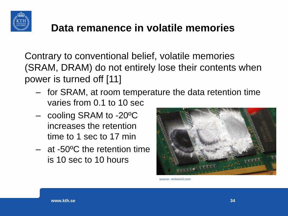
Data remanence in volatile memories
Contrary to conventional belief, volatile memories
(SRAM, DRAM) do not entirely lose their contents when
power is turned off [11]
– for SRAM, at room temperature the data retention time
varies from 0.1 to 10 sec
– cooling SRAM to -20ºC
increases the retention
time to 1 sec to 17 min
– at -50ºC the retention time
is 10 sec to 10 hours
www.kth.se
source: revision3.com
34

Data remanence in non-volatile memories
www.kth.se
It may take many cycles to erase data from a non-volatile memory (EEPROM, Flash, etc.)
Data was successfully recovered from the Flash memory PIC16F84 after 10 erase cycles [12]
To overcome this problem, it is recommended to erase data by writing all-0, all-1, and random data in the memory
source: [17]
35

Tamper response II: Physical destruction
www.kth.se
source: www.alphr.com
36
• Devices requiring very high security
can be physically destroyed using,
e.g. a small explosive charge
• But this option is not practical for
consumer electronics
– a chip on the left is destroyed in
response to tamper detection [13]
– $1500 hard drive,128GB

Tamper response II: Physical destruction
www.kth.se
Chip made of tempered glass can be triggered remotely to self
destruct. The silicon computer wafers is attached to a piece of
tempered glass that breaks when heated in one spot [14]
source: PARC, a Xerox company
37

IV. Tamper Evidence

Tamper Evidence
The goal is to ensure that visible evidence is left
behind when tampering occurs
- Tamper evidence may be provided by:
- Tamper-evident housing, e.g.
ultrasonic welding creates a
housing which is difficult to
open without a noticeable
damage
www.kth.se
source: http://www.eprovided.com/data-recovery-
blog/common-flash-drive-failure/
39

Tamper Evidence
- Enclosures with tamper-evident seals or locks
- Tamper-evident encapsulating materials or coatings
- "Bleeding" paint - paint of one color is mixed with micro-balloons containing paint of a contrasting color. If the painted surface is damaged, the colors blend and tampering is easy to identify [15]
www.kth.se
source: [1]
source: [1]
source: [1]
40

Tamper Evidence, cont.
- Logging the type of detected attack and its time
• For example, tamper
detection mechanisms in
electricity meters can record
a tamper event in the
memory and report it during
the next meter reading by an
authorized personnel. A
tamper LED is enabled and
date is recorded [16]
www.kth.se
source: [17]
41

Trusted Platform Modules/ Hardware Security Modules
WWW.KTH.SE

What about Trusted Platform Modules?
www.kth.se
Trusted Platform Module installed on a motherboard
source: en.wikipedia.org/wiki/Trusted_Platform_Module

Hardware-security enabled embedded system architecture
www.kth.se
source: [20]

www.kth.se

• Do not assume hardware to be trustworthy
• Instead, design a system to be tamper-resistant
• Use a combination of anti-tamper techniques
• A hacker will search for the weakest link and exploit it
Conclusions
www.kth.se
source: rocketgirlsolutions.com
46

References
[1] “Physical Protection: Anti-Tamper Mechanisms in CC Security Evaluations”, http://www.yourcreativesolutions. nl/ICCC10/proceedings/doc/pp/ALVARO_ORTEGA_EPOCHE&ESPRI_Physical_protection_Anti_tamper_mechanisms.pdf
[2] Printed Circuit Design & Fab Magazine, May 2012
[3] O. Kömmerling, “Design Principles for Tamper Resistant Smartcard Processors”, Smartcard’ 99
[4] Hacking the PIC18F1320, http://www.bunniestudios.com/blog/?page_id=40
[5] N. Li, et al., “Secure Key Storage Using State Machines” , ISMVL'2013, pp. 290-295
[6] S. Tao et al., “An Ultra-Energy-Efficient Temperature-Stable Physical Unclonable Function in 65nm CMOS”, Electronics Letters, 2016
[7] Joe Grand, Practical Secure Hardware Design for Embedded Systems, http://www.grandideastudio.com/wp-content/uploads/secure_embed_paper.pdf
[8] Securit Failures in Secure Devices, C. Tarnovsky, Black Hat 2008
[9] http://blog.ioactive.com/2007_12_01_archive.html
[10] http://www.adnas.com/sites/default/files/apdn.press.release.hi-rel.10.26.2015.pdf
www.kth.se 47

References, cont.
[11] S. Skorobogatov, “Physical Attacks on Tamper Resistance: Progress and Lessons”, Special Workshop on HW Assurance, 2011
[12] S. Skorobogatov, “Data Remanence in Flash Memory Devices”, CHES’2005
[13] Securedrives, http://securedrives.co.uk/
[14] http://www.livescience.com/52397-self-destructing-chip-secures-data.html
[15] M. Aarts, “Hardware Attacks Tamper Resistance, Tamper Response and Tamper Evidence”, http://maurice.aarts.info/papers/tamper_resistance_evidence.pdf
[16] M. Arora, P. Bhargava and S. Pickering, “MCF51EM256 Anti-tamper features : A leap towards robust smart metering solutions”
[17] M. Ford, “Lead Generation Tips – Things You Do Not Tell Prospects”, http://www.business2community.com/ sales-management/lead-generation-tips-things-you-do-not-tell-prospects-0422837 #OMBu1jkkPAmByVsp. 99
[18] NIST FIPS 140-2, “Security Requirements for Cryptographic Modules”. Federal Information Processing Standards Publication, became effective November 15, 2001
[19] NIST FIPS 140-3, “Security Requirements for Cryptographic Modules”. Federal Information Processing Standards Publication, proposed as a revision of FIPS 140-2 in 2007, abandoned in 2013
[20] M. Wolf, A. Weimerskrich, “Hardware Security Modules for Protecting Embedded Systems”, Escrypt White Paper
www.kth.se 48

Acknowledgement
To Joe Grand for his course “Hands-on Hardware
Hacking and Reverse Engineering” at Black Hat
Europe 2015
www.kth.se 49


![At125 Kopa Anti tamper ip65 reflectorkopaglobal.com/assets/at125.pdf · At125 Kopa Anti tamper ip65 reflector CRI >95, COI, ... Emax[lx] = Lux level at ... 811 LUMEN K0718 38º 4K](https://img.dokumen.tips/doc/110x75/5b5d38a27f8b9ad2198de69f/at125-kopa-anti-tamper-ip65-at125-kopa-anti-tamper-ip65-reflector-cri-95-coi.jpg)