Embed Size (px)
Citation preview
ANTI-LOCK BRAKE SYSTEM
1990 Nissan 240SX
1989-91 BRAKES Nissan Anti-Lock Brake System
NISSAN; MAXIMA, STANZA, 240SX & 300ZX
DESCRIPTION
Anti-Lock Brake System (ABS) is designed to allow driver tomaintain steering control during heavy braking. ABS system consists ofan Electronic Control Unit (ECU), actuator (electro-hydraulic unit),warning lights, wheel speed sensors, wiring and hydraulic lines. SeeFigs. 1-4. Actuator (electro-hydraulic unit) consists of a pump motor,accumulator, solenoid valves for each channel, actuator relay, pumpmotor relay, check valves and reservoirs. Maxima, Stanza and 300ZX usea 4-channel system, and 240SX uses a 3-channel system. ECU has self-diagnostic capability to alert driver in the event of a systemmalfunction. An LED located on the ABS Electronic Control Unit (ECU)will flash (indicating trouble codes) when warning light isilluminated.
NOTE: For more information on brake system, see BRAKE SYSTEM article in the BRAKES Section.
Fig. 1: Locating ABS Components (Maxima)Courtesy of Nissan Motor Co., U.S.A.
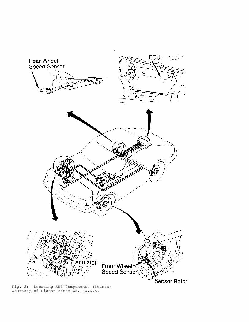
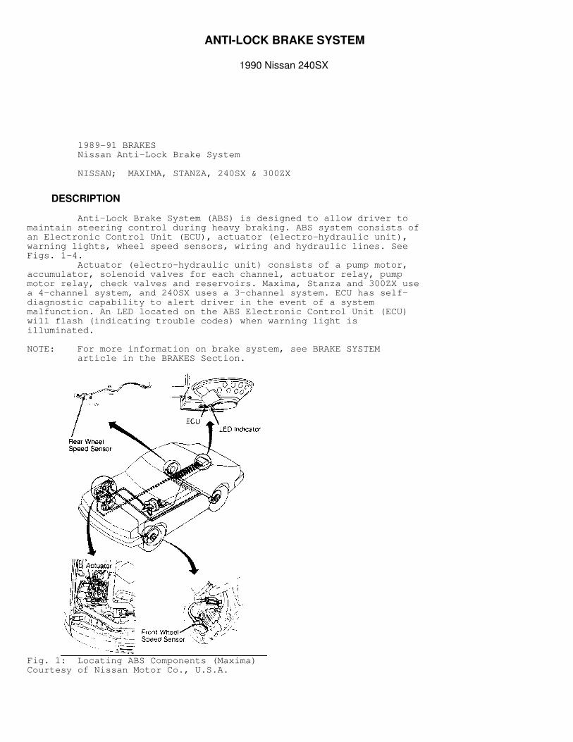
Fig. 2: Locating ABS Components (Stanza)Courtesy of Nissan Motor Co., U.S.A.
Fig. 3: Locating ABS Components (240SX)Courtesy of Nissan Motor Co., U.S.A.
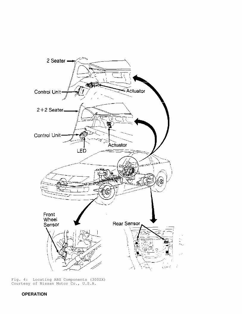
Fig. 4: Locating ABS Components (300ZX)Courtesy of Nissan Motor Co., U.S.A.
OPERATION
As vehicle is moving, speed sensors send an AC signal to ECU.ECU monitors the stoplight switch to determine when driver pressesbrake pedal. When brake pedal is pressed, ECU monitors signals fromeach speed sensor to determine rate of deceleration. If rate of deceleration from any speed sensor reaches apreprogrammed rate, ECU activates solenoid valves inside actuator.Solenoid valves are cycled to apply, release or maintain hydraulicpressure to each wheel in any combination. Regulating hydraulic pressure to each circuit prevents wheellock-up. When driver releases brake pedal, ECU deactivates solenoidvalves, placing brake system back into a conventional mode until ABSis again needed. If a fault is detected by ECU, an ANTI-LOCK light located onthe instrument panel illuminates. Although ECU deactivates ABS when afault is detected, conventional brake system is not be affected.
WARNING: Failure to depressurize ABS could lead to physical injury.
ANTI-LOCK BRAKE SAFETY PRECAUTIONS
* NEVER open a bleeder valve or loosen a hydraulic line while ABS is pressurized. * NEVER disconnect or reconnect any electrical connectors while ignition is on. Damage to ABS control unit may result. * DO NOT attempt to bleed hydraulic system without first referring to the appropriate article. * Only use specially designed brake hoses/lines on ABS-equipped vehicles. * DO NOT tap on speed sensor components (sensor, sensor rings). Speed rings must be pressed, NOT hammered into hubs. Striking these components can cause demagnetization or a loss of polarization, affecting the accuracy of the speed signal returning to the ABS control unit. * DO NOT mix tire sizes. Increasing the width, as long as tires remain close to the original diameter, is acceptable. Rolling diameter must be identical for all 4 tires. Some manufacturers recommend tires of the same brand, style and type. Failure to follow this precaution may cause inaccurate wheel speed readings. * DO NOT contaminate speed sensor components with grease. Only use recommended anti-corrosion coating. * When speed sensor components have been removed, ALWAYS check sensor-to-ring air gaps when applicable. These specifications can be found in each appropriate article. * ONLY use recommended brake fluids. DO NOT use silicone brake fluids in an ABS-equipped vehicle. * When installing transmitting devices (CB’s, telephones, etc.) on ABS-equipped vehicles, DO NOT locate the antenna near the ABS control unit (or any control unit). * Disconnect all on-board computers, when using electric welding equipment. * DO NOT expose the ABS control unit to prolonged periods of high heat (185
�
F/85�
C for 2 hours is generally considered a maximum limit).
BLEEDING BRAKE SYSTEM
To bleed system, unplug electrical connectors from actuator.Bleed brake system the same as a conventional system using appropriatebleeding sequence. See HYDRAULIC LINE BLEEDING SEQUENCE TABLE. Afterbleeding brakes, bleed front side of actuator and then rear side ofactuator. Use DOT 3 brake fluid only.
HYDRAULIC LINE BLEEDING SEQUENCE TABLE�����������������������������������������������������������������������������������������
Application Sequence
Maxima & Stanza ................. Left Rear Right Front Right Rear Left Front
240SX & 300ZX ................... Left Rear Right Rear Right Front Left Front�����������������������������������������������������������������������������������������
ADJUSTMENTS
BRAKE PEDAL HEIGHT & FREE PLAY
1) Measure pedal height from pressure face of pedal pad tofloor pan insulator, without carpet. See BRAKE PEDAL HEIGHTSPECIFICATIONS TABLE. 2) To adjust to pedal height, loosen brake booster input rodlock nut, and rotate input rod to attain proper height. Tighten locknut and adjust stoplight switch. Ensure pedal free play is .04-.12"(1-3 mm).
BRAKE PEDAL HEIGHT SPECIFICATIONS TABLE�������������������������������������������������������������������������������������������������������������
Application Pedal Height - In. (mm)
Maxima & Stanza Auto. Trans. .................. 6.65-7.05 (169-179) Man. Trans. ................... 6.26-6.65 (159-169)240SX Auto. Trans. .................. 7.32-7.72 (186-196) Man. Trans. ................... 6.97-7.36 (177-187)300ZX Auto. Trans. .................. 7.68-8.07 (195-205) Man. Trans. ................... 7.32-7.72 (186-196)�������������������������������������������������������������������������������������������������������������
LOAD-SENSING PROPORTIONING VALVE
NOTE: If pressure cannot be adjusted to within specifications, replace entire valve assembly as a unit.
Pressure Adjustment (Maxima) 1) With one person inside vehicle, set rear axle load to 1323lbs. (595 kg) of weight in trunk. Attach 2 pressure gauges, one tofront and one to rear brake bleeder. Bleed air from front and rearbleeders. 2) Depress brake pedal until front brake pressure reading is711 psi (50 kg/cm
�
). Check rear brake pressure. See LSPV PRESSURESPECIFICATIONS TABLE. Depress brake pedal until front brake pressurereading is 1422 psi (100 kg/cm
�
). Check rear brake pressure. See LSPVPRESSURE SPECIFICATIONS TABLE.
CAUTION: Check rear brake pressure 2 seconds after front brake pressure reaches specified value.
LSPV PRESSURE SPECIFICATIONS TABLE���������������������������������������������������������������������������������������������������������������������������������
Front Brake Pressure Rear Brake PressureApplication psi (kg/cm
�
) psi (kg/cm�
)
Maxima ................ 711 (50) ............ 555-697 (39-49)Maxima ............... 1422 (100) ........... 739-939 (52-66)���������������������������������������������������������������������������������������������������������������������������������
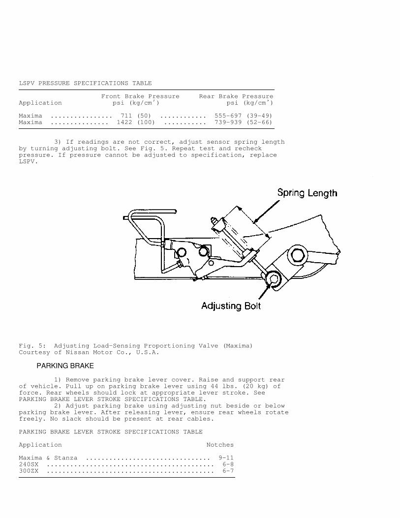
3) If readings are not correct, adjust sensor spring lengthby turning adjusting bolt. See Fig. 5. Repeat test and recheckpressure. If pressure cannot be adjusted to specification, replaceLSPV.
Fig. 5: Adjusting Load-Sensing Proportioning Valve (Maxima)Courtesy of Nissan Motor Co., U.S.A.
PARKING BRAKE
1) Remove parking brake lever cover. Raise and support rearof vehicle. Pull up on parking brake lever using 44 lbs. (20 kg) offorce. Rear wheels should lock at appropriate lever stroke. SeePARKING BRAKE LEVER STROKE SPECIFICATIONS TABLE. 2) Adjust parking brake using adjusting nut beside or belowparking brake lever. After releasing lever, ensure rear wheels rotatefreely. No slack should be present at rear cables.
PARKING BRAKE LEVER STROKE SPECIFICATIONS TABLE�������������������������������������������������������������������������������������������������������������
Application Notches
Maxima & Stanza ................................ 9-11240SX ........................................... 6-8300ZX ........................................... 6-7�������������������������������������������������������������������������������������������������������������
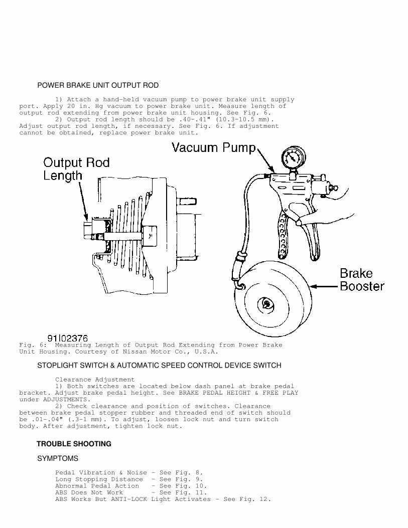
POWER BRAKE UNIT OUTPUT ROD
1) Attach a hand-held vacuum pump to power brake unit supplyport. Apply 20 in. Hg vacuum to power brake unit. Measure length ofoutput rod extending from power brake unit housing. See Fig. 6. 2) Output rod length should be .40-.41" (10.3-10.5 mm).Adjust output rod length, if necessary. See Fig. 6. If adjustmentcannot be obtained, replace power brake unit.
Fig. 6: Measuring Length of Output Rod Extending from Power BrakeUnit Housing. Courtesy of Nissan Motor Co., U.S.A.
STOPLIGHT SWITCH & AUTOMATIC SPEED CONTROL DEVICE SWITCH
Clearance Adjustment 1) Both switches are located below dash panel at brake pedalbracket. Adjust brake pedal height. See BRAKE PEDAL HEIGHT & FREE PLAYunder ADJUSTMENTS. 2) Check clearance and position of switches. Clearancebetween brake pedal stopper rubber and threaded end of switch shouldbe .01-.04" (.3-1 mm). To adjust, loosen lock nut and turn switchbody. After adjustment, tighten lock nut.
TROUBLE SHOOTING
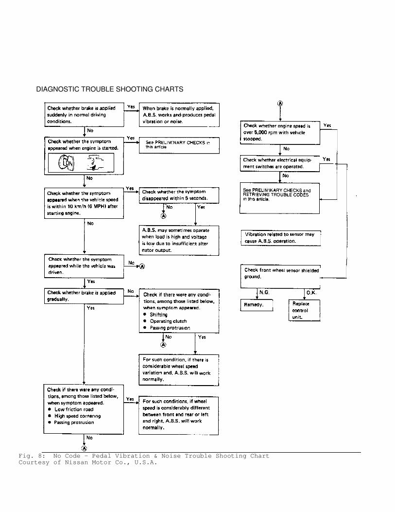
SYMPTOMS
Pedal Vibration & Noise - See Fig. 8. Long Stopping Distance - See Fig. 9. Abnormal Pedal Action - See Fig. 10. ABS Does Not Work - See Fig. 11. ABS Works But ANTI-LOCK Light Activates - See Fig. 12.
ABS Works Too Frequently - See Fig. 13, 14, 15, or 16. ANTI-LOCK Light On, LED Does Not Flash - See Fig. 17.
DIAGNOSIS & TESTING
NOTE: Actuator testing requires the use of Tester (KV999P1000) and Adapter (KV999P1010).
PRE-INSPECTION
1) To correctly diagnose system, inspect all brake componentsfor wear or damage. Ensure hydraulic system is full and no leaksexist. Ensure brake booster is functioning properly. Check air gap ateach speed sensor. See WHEEL SPEED SENSOR AIR GAP TABLE. 2) On 240SX, measure rear speed sensor air gap by insertingfeeler gauge between sensor mating face on differential to exciterring on pinion flange. Measure speed sensor pole piece from sensormating face to pole piece tip. Subtract sensor measurement fromdifferential measurement to obtain air gap. 3) On all models, if air gap exceeds specification, replacespeed sensor, pinion flange (240SX) or wheel hub assembly. Inspectrotor teeth. Replace rotor (and companion flange, if necessary) ifteeth are damaged. Go to PRELIMINARY CHECK.
WHEEL SPEED SENSOR AIR GAP TABLE�������������������������������������������������������������������������������������������������������������
Application In. (mm)
Maxima & Stanza Front & Rear ................. .008-.039 (.20-1.00)240SX Front ......................... .011-.030 (.28-.75) Rear .......................... .014-.025 (.35-.63)300ZX Front ......................... .009-.028 (.23-.71) Rear .......................... .002-.037 (.05-.94)�������������������������������������������������������������������������������������������������������������
PRELIMINARY CHECK
1) After completing PRE-INSPECTION, check resistance of eachwheel speed sensor. If resistance is not 800-1200 ohms, replacesensor, and retest. If resistance is okay, turn ignition on and checkANTI-LOCK warning light operation. Light should illuminate whenignition is turned on. If light does not come on, check fuse, wiringand bulb for fault. 2) If warning light comes on, start engine and observe ANTI-LOCK warning light. Warning light should go out when engine isstarted. If warning light stays on after starting engine, leaveignition on and go to RETRIEVING TROUBLE CODES. If light goes offafter starting engine, go to next step. 3) Drive vehicle for at least one minute at a minimum speedof 19 MPH. If warning light stays off during road test, no fault ispresent in ABS. If light comes on and stays on during road test, leaveignition on and go to RETRIEVING TROUBLE CODES. Ensure shielding wireground for each sensor and ground for pump motors have continuity toground.
RETRIEVING TROUBLE CODES
NOTE: ECU can store (and indicate with LED) only one trouble code at a time. After indicated code circuit is repaired, road
test vehicle and recheck codes for additional indicated faults.
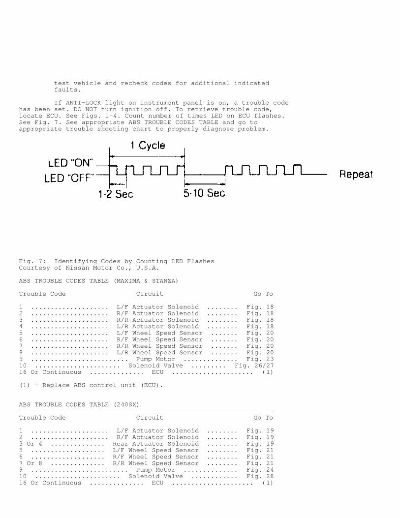
If ANTI-LOCK light on instrument panel is on, a trouble codehas been set. DO NOT turn ignition off. To retrieve trouble code,locate ECU. See Figs. 1-4. Count number of times LED on ECU flashes.See Fig. 7. See appropriate ABS TROUBLE CODES TABLE and go toappropriate trouble shooting chart to properly diagnose problem.
Fig. 7: Identifying Codes by Counting LED FlashesCourtesy of Nissan Motor Co., U.S.A.
ABS TROUBLE CODES TABLE (MAXIMA & STANZA)���������������������������������������������������������������������������������������������������������������������������������
Trouble Code Circuit Go To
1 .................... L/F Actuator Solenoid ........ Fig. 182 .................... R/F Actuator Solenoid ........ Fig. 183 .................... R/R Actuator Solenoid ........ Fig. 184 .................... L/R Actuator Solenoid ........ Fig. 185 .................... L/F Wheel Speed Sensor ....... Fig. 206 .................... R/F Wheel Speed Sensor ....... Fig. 207 .................... R/R Wheel Speed Sensor ....... Fig. 208 .................... L/R Wheel Speed Sensor ....... Fig. 209 ......................... Pump Motor .............. Fig. 2310 ...................... Solenoid Valve ......... Fig. 26/2716 Or Continuous .............. ECU ..................... (1)
(1) - Replace ABS control unit (ECU).���������������������������������������������������������������������������������������������������������������������������������
ABS TROUBLE CODES TABLE (240SX)���������������������������������������������������������������������������������������������������������������������������������
Trouble Code Circuit Go To
1 .................... L/F Actuator Solenoid ........ Fig. 192 .................... R/F Actuator Solenoid ........ Fig. 193 Or 4 .............. Rear Actuator Solenoid ........ Fig. 195 ................... L/F Wheel Speed Sensor ........ Fig. 216 ................... R/F Wheel Speed Sensor ........ Fig. 217 Or 8 .............. R/R Wheel Speed Sensor ........ Fig. 219 ......................... Pump Motor .............. Fig. 2410 ...................... Solenoid Valve ............ Fig. 2816 Or Continuous .............. ECU ..................... (1)
(1) - Replace ABS control unit (ECU).���������������������������������������������������������������������������������������������������������������������������������
ABS TROUBLE CODES TABLE (300ZX)���������������������������������������������������������������������������������������������������������������������������������
Code Circuit Go To
1 ...................... L/F Actuator Solenoid ...... Fig. 192 ...................... R/F Actuator Solenoid ...... Fig. 193 Or 4 ................ Rear Actuator Solenoid ...... Fig. 195 ...................... L/F Speed Sensor ........... Fig. 226 ...................... R/F Speed Sensor ........... Fig. 227 ...................... R/R Speed Sensor ........... Fig. 228 ...................... L/R Speed Sensor ........... Fig. 229 ................ Actuator Motor, Motor Relay ...... Fig. 2510 .................... Actuator Sol. Relay ......... Fig. 2916 ............................ ECU .................... (1)
(1) - Replace ABS control unit (ECU).���������������������������������������������������������������������������������������������������������������������������������
REMOVAL & INSTALLATION
ACTUATOR
Removal & Installation Disconnect negative battery cable. Disconnect electricalconnectors and hydraulic lines at actuator. Remove mounting bolts andactuator. To install, reverse removal procedure. Bleed brake system.See BLEEDING BRAKE SYSTEM.
ELECTRONIC CONTROL UNIT (ECU)
CAUTION: Before servicing ECU, ground yourself and ground the work area to discharge stored electricity. As little as a 30-volt charge created by static electricity can cause a total or degrading failure in ECU or other electronic components containing integrated circuits.
Removal & Installation Disconnect negative battery cable. Locate ECU. See Figs. 1-4.Disconnect electrical connector and remove ECU. To install, reverseremoval procedure.
WHEEL SPEED SENSORS
Removal & Installation To remove front sensor or rear wheel speed sensor, removesensor retaining bolt and sensor. To install, reverse removalprocedure. Tighten sensor mounting bolts to specification. See TORQUESPECIFICATIONS TABLE.
WHEEL SPEED SENSOR ROTORS
Removal & Installation 1) To remove front wheel speed sensor rotor, remove steeringhub and axle assembly. To remove rear wheel speed sensor rotor onMaxima and Stanza, remove rear wheel hub bearing. 2) To remove rear speed sensor rotor on 240SX, remove driveshaft and drive pinion flange. To remove rear speed sensor rotor on300ZX, remove with differential side flange after removing axle shaft.To install components, reverse removal procedure.
DIAGNOSTIC TROUBLE SHOOTING CHARTS
Fig. 8: No Code - Pedal Vibration & Noise Trouble Shooting ChartCourtesy of Nissan Motor Co., U.S.A.
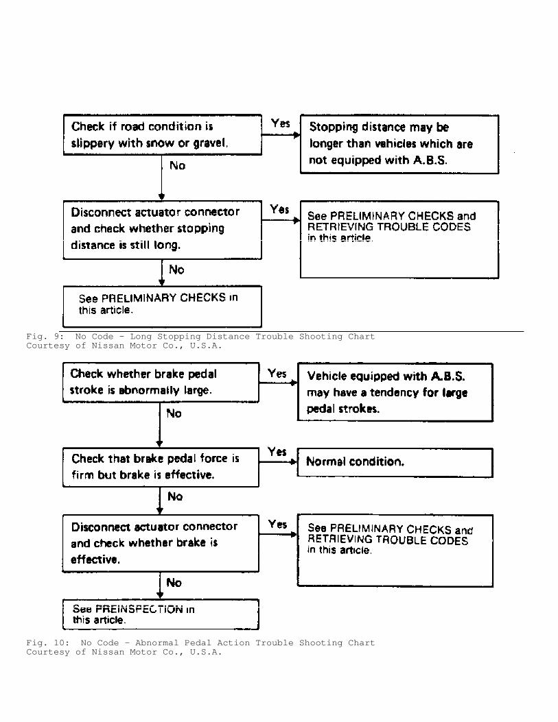
Fig. 9: No Code - Long Stopping Distance Trouble Shooting ChartCourtesy of Nissan Motor Co., U.S.A.
Fig. 10: No Code - Abnormal Pedal Action Trouble Shooting ChartCourtesy of Nissan Motor Co., U.S.A.
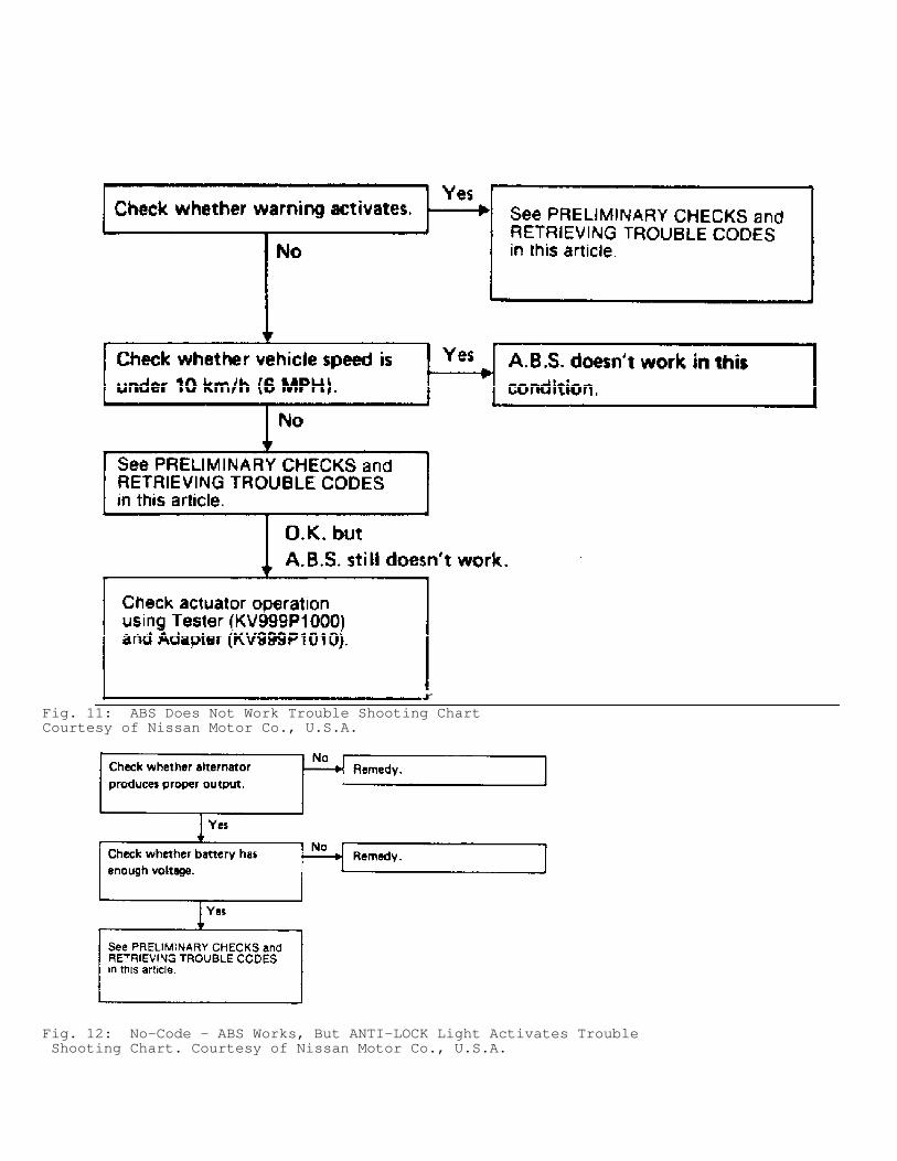
Fig. 11: ABS Does Not Work Trouble Shooting ChartCourtesy of Nissan Motor Co., U.S.A.
Fig. 12: No-Code - ABS Works, But ANTI-LOCK Light Activates Trouble Shooting Chart. Courtesy of Nissan Motor Co., U.S.A.
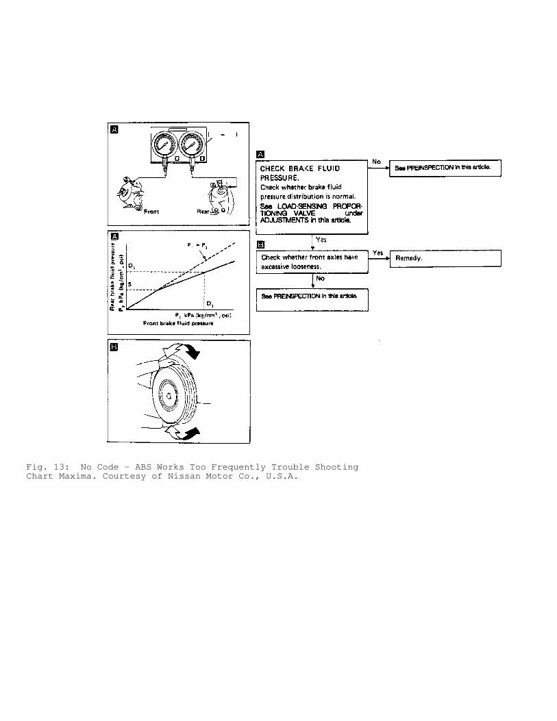
Fig. 13: No Code - ABS Works Too Frequently Trouble ShootingChart Maxima. Courtesy of Nissan Motor Co., U.S.A.
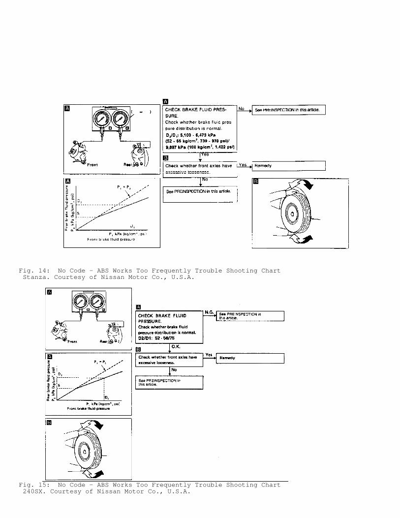
Fig. 14: No Code - ABS Works Too Frequently Trouble Shooting Chart Stanza. Courtesy of Nissan Motor Co., U.S.A.
Fig. 15: No Code - ABS Works Too Frequently Trouble Shooting Chart 240SX. Courtesy of Nissan Motor Co., U.S.A.
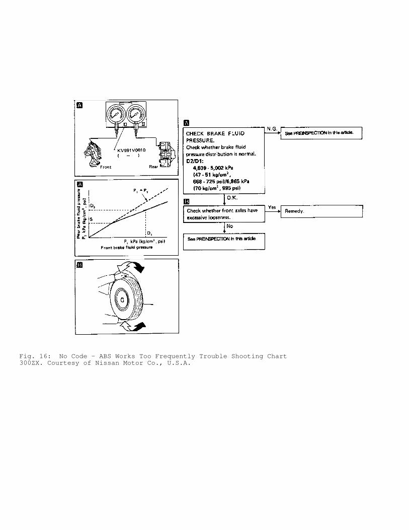
Fig. 16: No Code - ABS Works Too Frequently Trouble Shooting Chart300ZX. Courtesy of Nissan Motor Co., U.S.A.
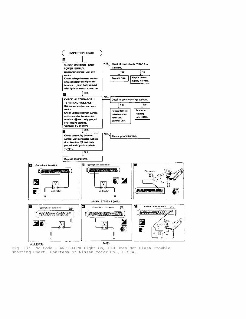
Fig. 17: No Code - ANTI-LOCK Light On, LED Does Not Flash TroubleShooting Chart. Courtesy of Nissan Motor Co., U.S.A.
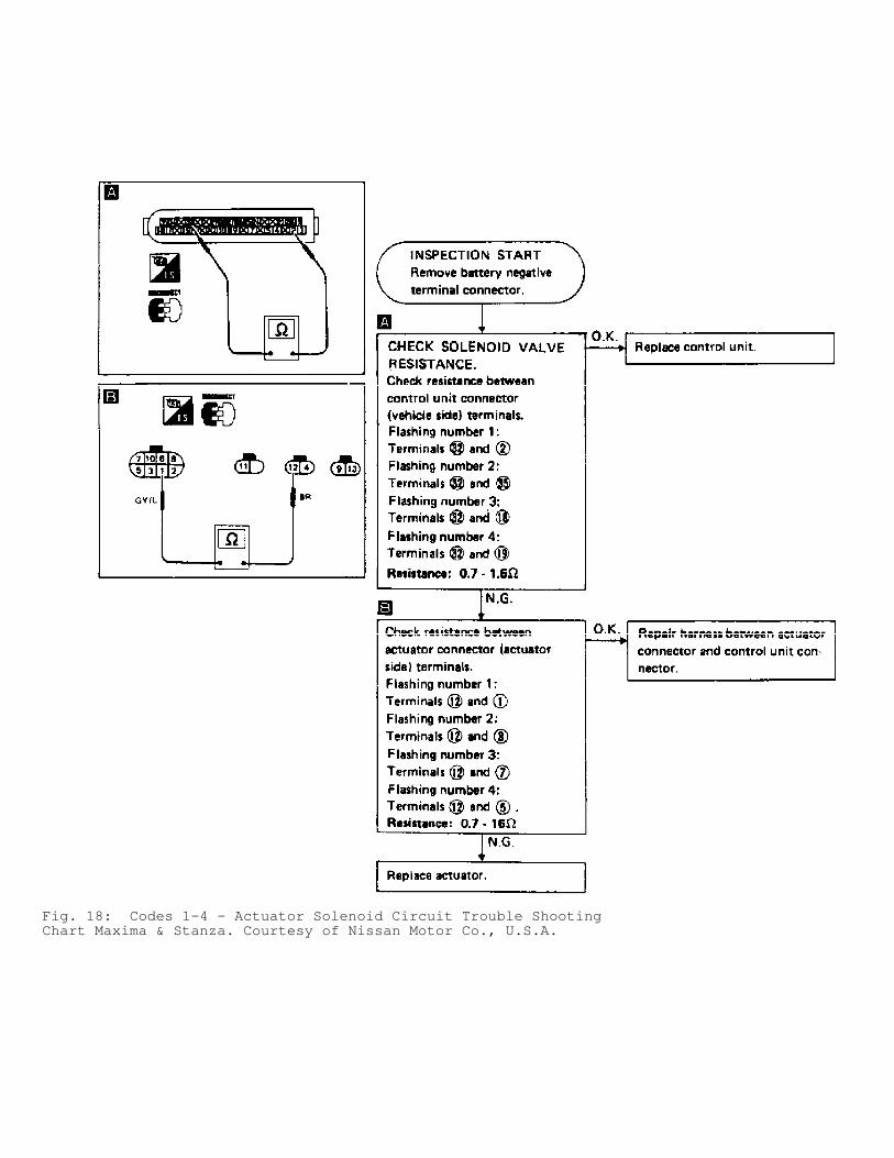
Fig. 18: Codes 1-4 - Actuator Solenoid Circuit Trouble ShootingChart Maxima & Stanza. Courtesy of Nissan Motor Co., U.S.A.
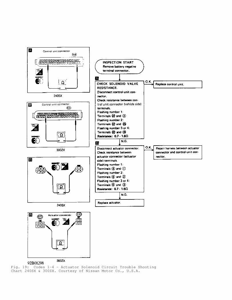
Fig. 19: Codes 1-4 - Actuator Solenoid Circuit Trouble ShootingChart 240SX & 300ZX. Courtesy of Nissan Motor Co., U.S.A.

Fig. 20: Codes 5-8 - Wheel Speed Sensor Circuit Trouble ShootingChart Maxima & Stanza. Courtesy of Nissan Motor Co., U.S.A.
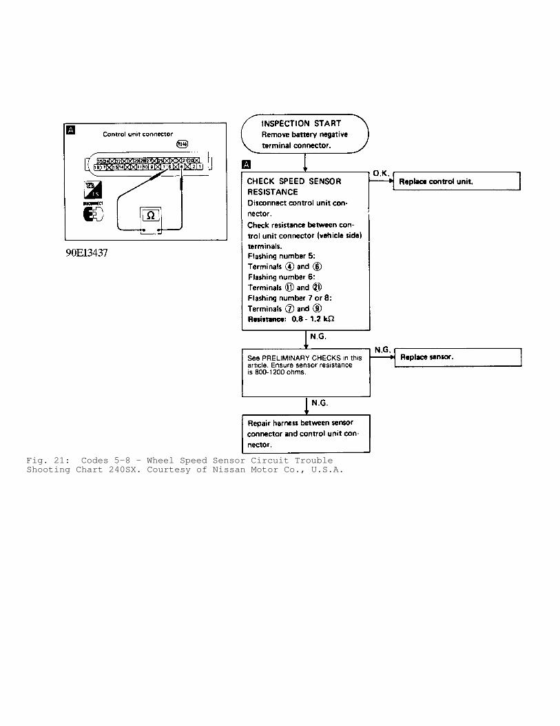
Fig. 21: Codes 5-8 - Wheel Speed Sensor Circuit TroubleShooting Chart 240SX. Courtesy of Nissan Motor Co., U.S.A.
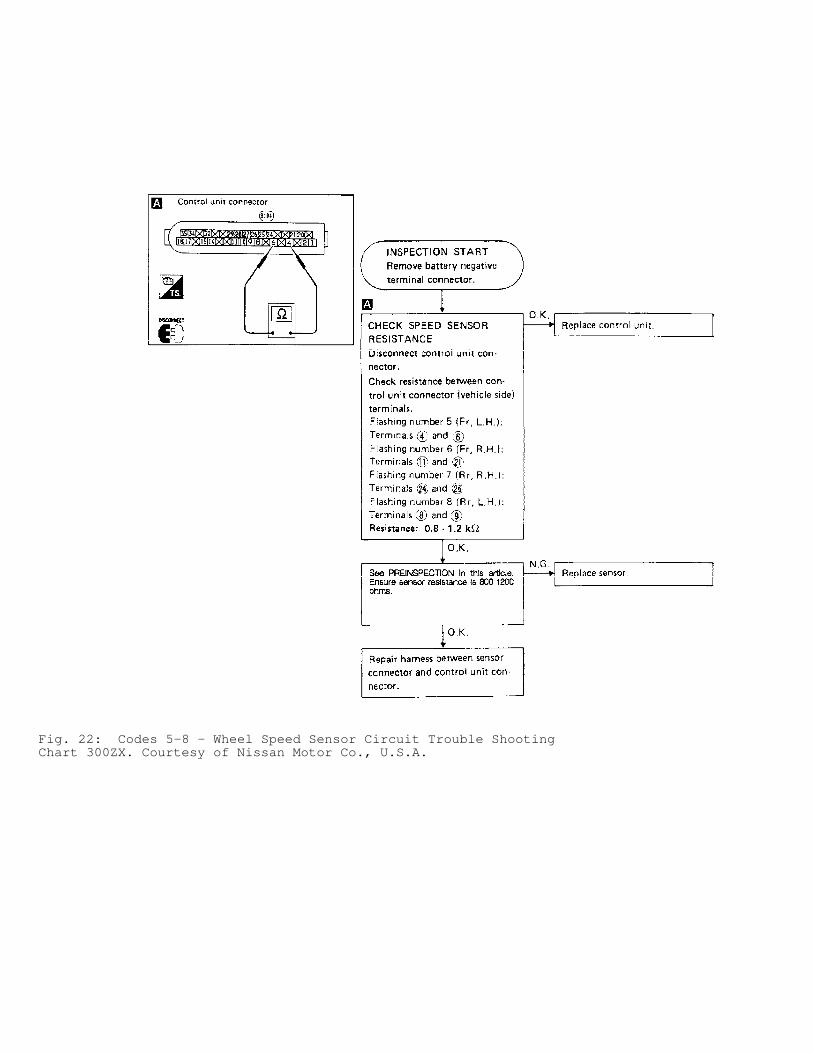
Fig. 22: Codes 5-8 - Wheel Speed Sensor Circuit Trouble ShootingChart 300ZX. Courtesy of Nissan Motor Co., U.S.A.
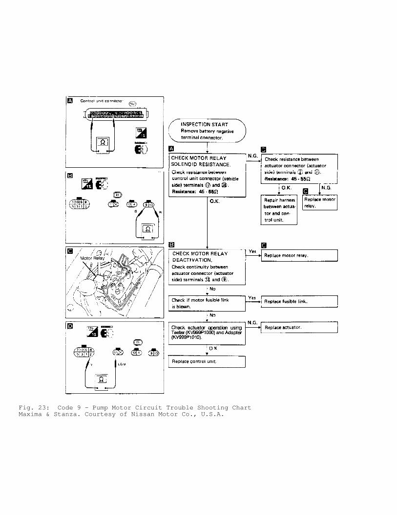
Fig. 23: Code 9 - Pump Motor Circuit Trouble Shooting ChartMaxima & Stanza. Courtesy of Nissan Motor Co., U.S.A.
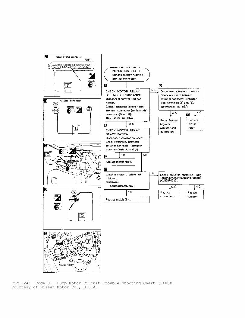
Fig. 24: Code 9 - Pump Motor Circuit Trouble Shooting Chart (240SX)Courtesy of Nissan Motor Co., U.S.A.
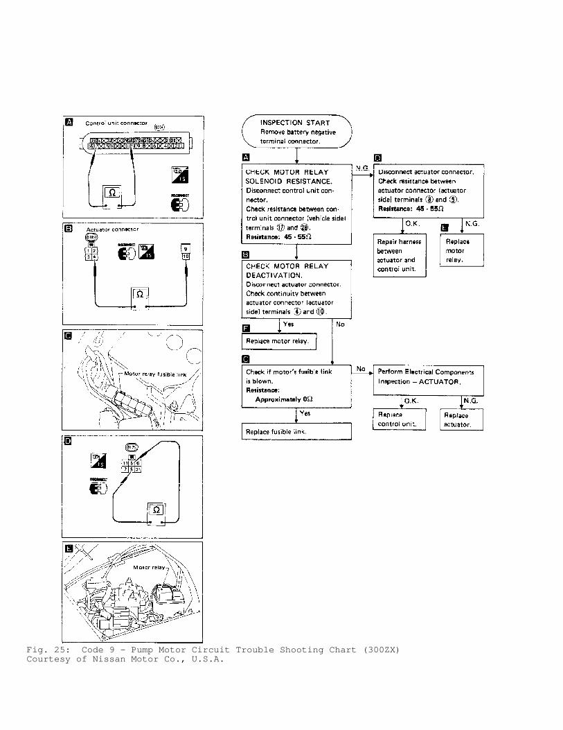
Fig. 25: Code 9 - Pump Motor Circuit Trouble Shooting Chart (300ZX)Courtesy of Nissan Motor Co., U.S.A.
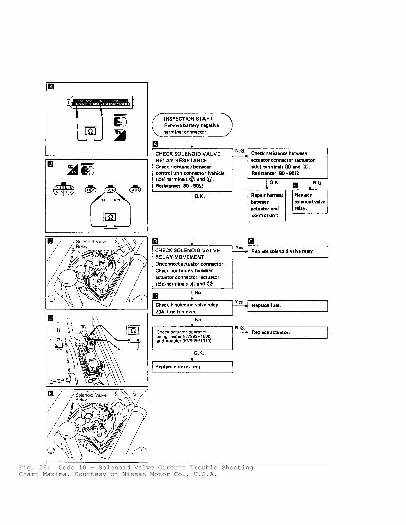
Fig. 26: Code 10 - Solenoid Valve Circuit Trouble ShootingChart Maxima. Courtesy of Nissan Motor Co., U.S.A.
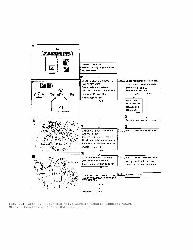
Fig. 27: Code 10 - Solenoid Valve Circuit Trouble Shooting ChartStanza. Courtesy of Nissan Motor Co., U.S.A.
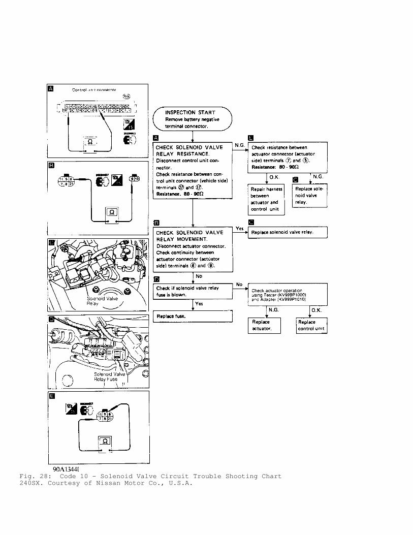
Fig. 28: Code 10 - Solenoid Valve Circuit Trouble Shooting Chart240SX. Courtesy of Nissan Motor Co., U.S.A.
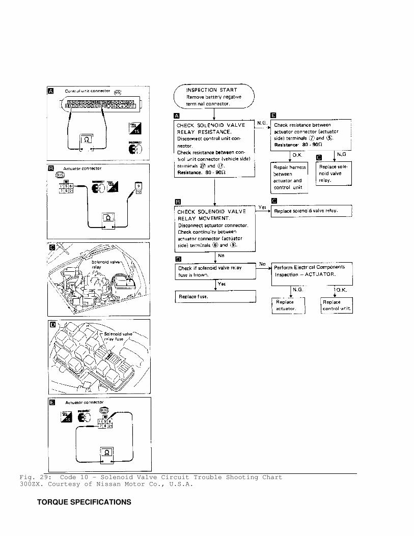
Fig. 29: Code 10 - Solenoid Valve Circuit Trouble Shooting Chart300ZX. Courtesy of Nissan Motor Co., U.S.A.
TORQUE SPECIFICATIONS
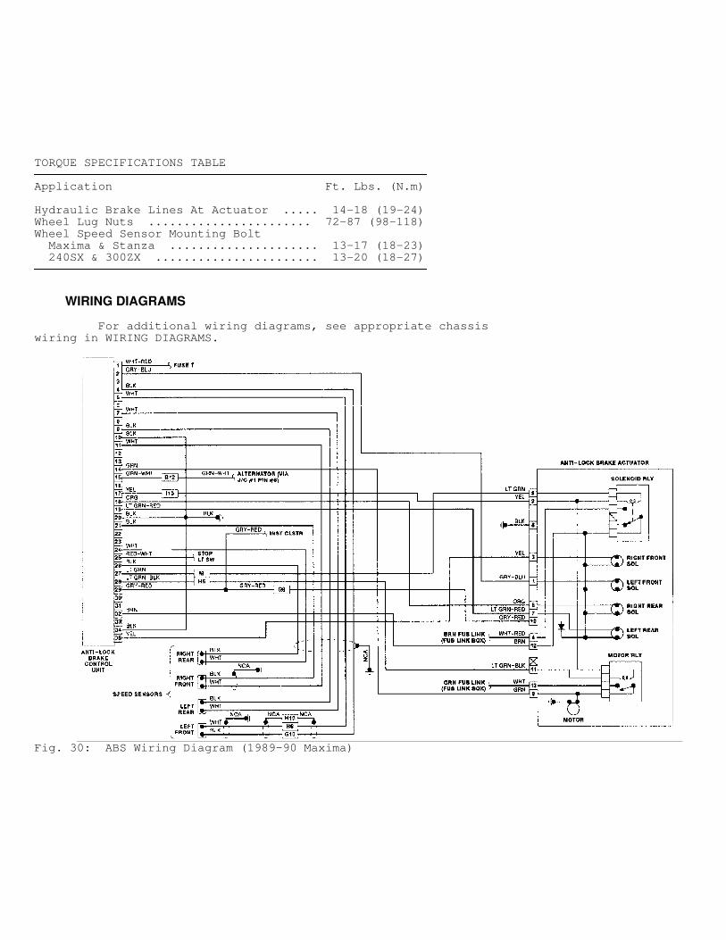
TORQUE SPECIFICATIONS TABLE�������������������������������������������������������������������������������������������������������������
Application Ft. Lbs. (N.m)
Hydraulic Brake Lines At Actuator ..... 14-18 (19-24)Wheel Lug Nuts ....................... 72-87 (98-118)Wheel Speed Sensor Mounting Bolt Maxima & Stanza ..................... 13-17 (18-23) 240SX & 300ZX ....................... 13-20 (18-27)�������������������������������������������������������������������������������������������������������������
WIRING DIAGRAMS
For additional wiring diagrams, see appropriate chassiswiring in WIRING DIAGRAMS.
Fig. 30: ABS Wiring Diagram (1989-90 Maxima)
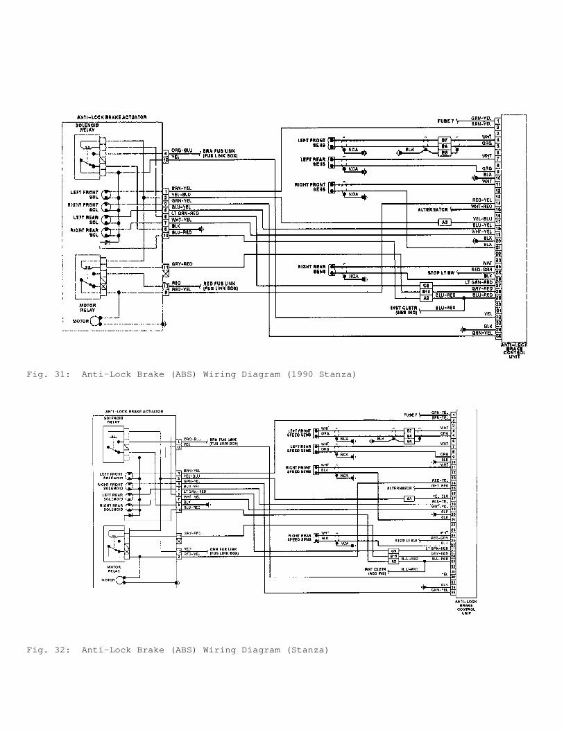
Fig. 31: Anti-Lock Brake (ABS) Wiring Diagram (1990 Stanza)
Fig. 32: Anti-Lock Brake (ABS) Wiring Diagram (Stanza)
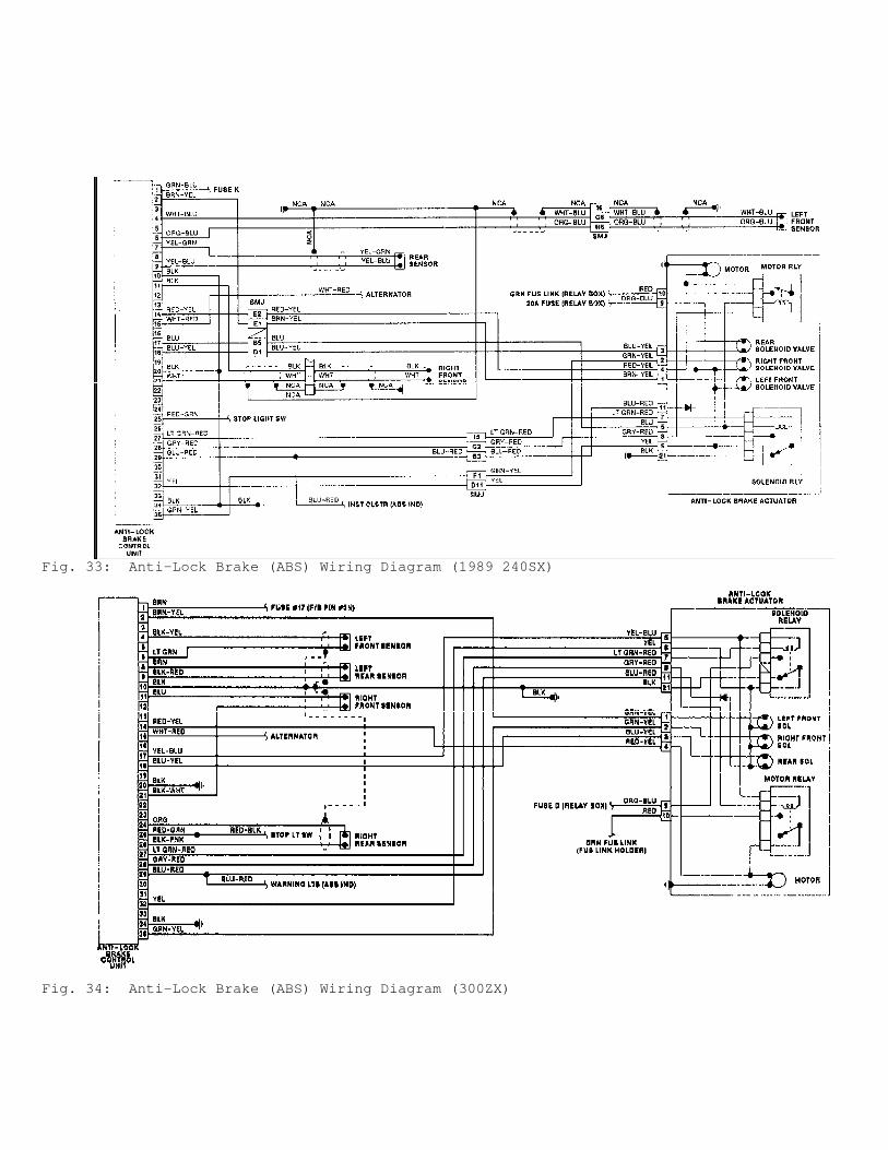
Fig. 33: Anti-Lock Brake (ABS) Wiring Diagram (1989 240SX)
Fig. 34: Anti-Lock Brake (ABS) Wiring Diagram (300ZX)