Embed Size (px)
Citation preview

[email protected] www.anteral.com +34 948 48 84 58 Edificio Jerónimo de Ayanz. Calle Tajonar 22. 31006 – Pamplona (Spain)
Product Catalogue
2020
1
[email protected] www.anteral.com +34 948 48 84 58 Edificio Jerónimo de Ayanz. Calle Tajonar 22. 31006 – Pamplona (Spain)
Introduction
Anteral is formed by a highly qualified team committed with the client necessities that results in a company with a culture based on the innovation, team building and self-improvement.
Following this culture, Anteral develops innovative technology complying with the most challenging requirements in the field of antennas, passives and radar technology for space, telecommunications, defence, smart cities and industry and academia sectors, among others.
Antennas & Passives Components
Anteral counts with a large heritage in the development of antennas and passives components meeting the most demanding requirements and state-of-the-art specifications. Anteral designs, fabricates, and tests its devices based on high quality rules and processes. Thanks to its large heritage on the Aerospace sector, where Anteral counts with its developments on board of more than 12 satellites, Anteral offers outstanding performance products that can be of great relevance for many applications and uses.
Radar Technology
R&D is part of Anteral´s DNA and this is how its Radar technology development
line was born. Anteral has made used of its knowhow on the RF field to develop its own radar products with the aim of boosting innovative applications and uses. Anteral´s radar technology can be employed on Smart Cities, Industrial, Education and Health sectors, always taking care of the R&D part and creating new and innovative products and applications. This development line is known under the brand uRAD (Universal Radar, www.urad.es) and counts with a proprietary international patent.
Ad-hoc Developments
Apart from Anteral´s products, the company also offers ad-hoc designs considering the client´s requirement and developing custom solutions for them
1
[email protected] www.anteral.com +34 948 48 84 58 Edificio Jerónimo de Ayanz. Calle Tajonar 22. 31006 – Pamplona (Spain)
Quality Products and Services
Quality Management System
Anteral counts with high quality standards that provide assurance management procedures. Anteral counts, from its creation, with the ISO 9001 certification that allows the company to work following procedures and protocols to maintain a perfect track of the worked performed.
At the moment, Anteral counts with an ISO9001:2015 certification that provides quality and control processes for the complete business structure which is renewed every year.
The Quality Management Procedures gathered within Anteral´s ISO9001:2015 documentation are divided into different processes that determine the way to proceed for Commercial Management (FP01), Design & Development (FP02), Procurement Management (FP03), Production Management (FP04), Human Resources (FP05), Infrastructure & Equipment (FP06), Information & Communication (FP07), Management Responsibility (FP08), Test & Evaluation (FP09) and Progress Management (FP10). These procedures gather the complete management structure and assures a high-quality management system.
Chain of Suppliers
Anteral always work with workshops and companies that count with ISO 9001, and ISO 9100 for Space programs to maintain a high-quality protocol. This way, a product assurance plan is guaranteed following both certifications and having always a fluent an easy communication between the parts involved.
This way, Anteral can provide outstanding products developed under the most restrictive quality procedures complying with the client´s requirements and necessities.
Heritage
Apart from the Quality Assurance Management System, Anteral counts with a broad heritage working for the Aerospace sector among others. Anteral has worked in more than 15 SatCom programs together with renowned companies and research centres such as Airbus DS, Airbus UK, GMV, INDRA, ESA, etc.
Moreover, Anteral has sold its products and services regarding high performance Antennas and RF components as well as Radar Technology to important companies and research centres along the world such as: JPL-NASA, MIT, U.S. Naval Research Laboratory, BQ, Intel, ETH Zürich, etc.
Finally, Anteral has participated in more than 10 R&D programs regional, national and international (FP7, H2020, SME Instrument, etc) with important consortiums formed by companies and universities like Ericsson, Chalmers, KTH, Infineon, Fraunhofer, Rutherford Appleton Laboratory, etc.
2
[email protected] www.anteral.com +34 948 48 84 58 Edificio Jerónimo de Ayanz. Calle Tajonar 22. 31006 – Pamplona (Spain)
Content list
1. Standard Gain Horn Antennas (SGH) .................................................................... 3
2. Scalar Feed Horn Antenna (SFHA) ........................................................................ 5
3. Lens Horn Antenna (LHA) ...................................................................................... 6
4. Focusing Lens Horn Antenna (LHA-F) ................................................................... 9
5. High-Gain Lens Horn Antenna (HGLHA).............................................................. 11
6. Cassegrain Reflector System (CRS) .................................................................... 13
7. Trihedral Corner Reflectors (TTCR) ..................................................................... 16
8. Near Field Probes (NFP) ..................................................................................... 17
9. Orthomode Transducers (OMT) ........................................................................... 19
10. Polarizers (POL) ............................................................................................... 21
11. Dual Linear Polarized Scalar Feed Horn Antenna (DLPSFHA) ......................... 22
12. Dual Circular Polarized Scalar Feed Horn Antenna (DCPSFHA) ...................... 24
13. Dual Linear Polarized Lens Horn Antenna (DLPLHA) ....................................... 25
14. Dual Circular Polarized Lens Horn Antenna (DCPLHA) .................................... 27
15. Filters & Multiplexers (FILT - MUX) .................................................................. 28
16. Log-Periodic Antennas (LOG-P) ....................................................................... 30
17. Wire Grid Polarizers (WGP) ............................................................................. 32
18. Quarter Wave Plates (QWP) ............................................................................ 34
19. Radar (by uRAD) .............................................................................................. 36
3
[email protected] www.anteral.com +34 948 48 84 58 Edificio Jerónimo de Ayanz. Calle Tajonar 22. 31006 – Pamplona (Spain)
1. Standard Gain Horn Antennas (SGH)
Features
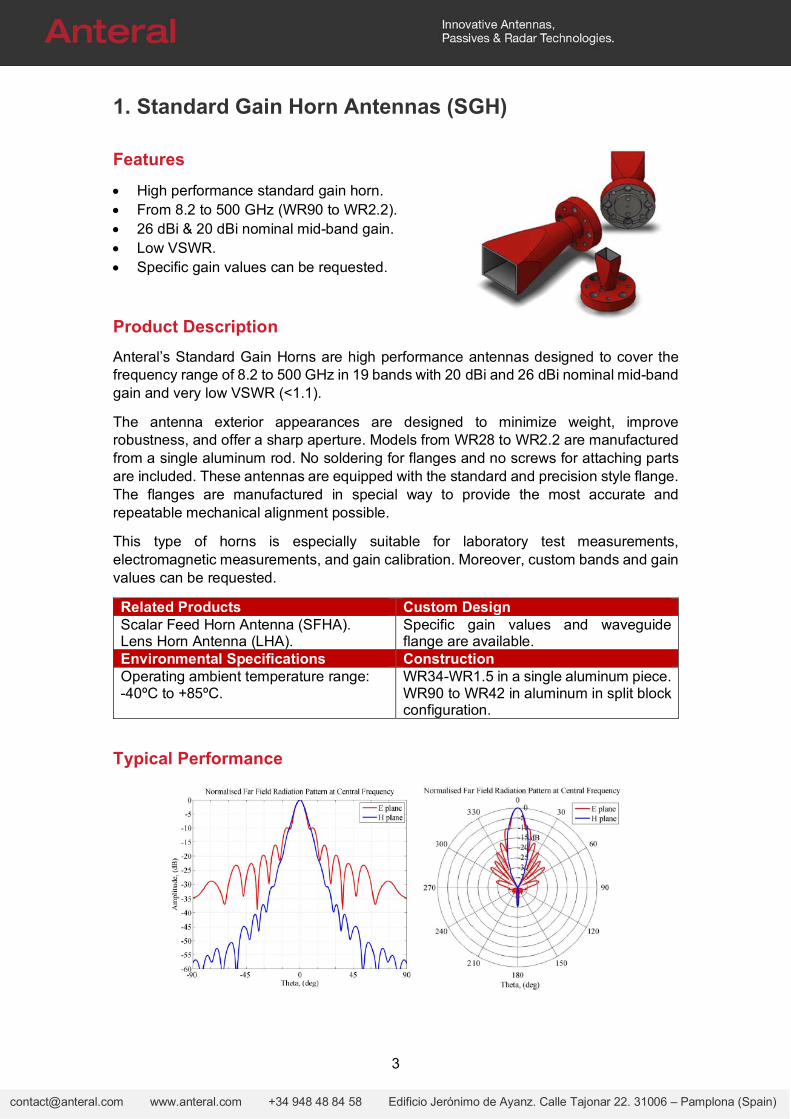
High performance standard gain horn. From 8.2 to 500 GHz (WR90 to WR2.2). 26 dBi & 20 dBi nominal mid-band gain. Low VSWR. Specific gain values can be requested.
Product Description
Anteral’s Standard Gain Horns are high performance antennas designed to cover the frequency range of 8.2 to 500 GHz in 19 bands with 20 dBi and 26 dBi nominal mid-band gain and very low VSWR (<1.1).
The antenna exterior appearances are designed to minimize weight, improve robustness, and offer a sharp aperture. Models from WR28 to WR2.2 are manufactured from a single aluminum rod. No soldering for flanges and no screws for attaching parts are included. These antennas are equipped with the standard and precision style flange. The flanges are manufactured in special way to provide the most accurate and repeatable mechanical alignment possible.
This type of horns is especially suitable for laboratory test measurements, electromagnetic measurements, and gain calibration. Moreover, custom bands and gain values can be requested.
Related Products Custom DesignScalar Feed Horn Antenna (SFHA). Lens Horn Antenna (LHA).
Specific gain values and waveguide flange are available.
Environmental Specifications ConstructionOperating ambient temperature range: -40ºC to +85ºC.
WR34-WR1.5 in a single aluminum piece.WR90 to WR42 in aluminum in split block configuration.
Typical Performance
4
[email protected] www.anteral.com +34 948 48 84 58 Edificio Jerónimo de Ayanz. Calle Tajonar 22. 31006 – Pamplona (Spain)
Electrical Specifications
Model Frequency
(GHz) VSWR
(:1) Directivity
(dBi)
3dB beamwidth (deg), Typ
Sidelobe (dB), Typ
Length
E-plane H-plane E-plane H-plane
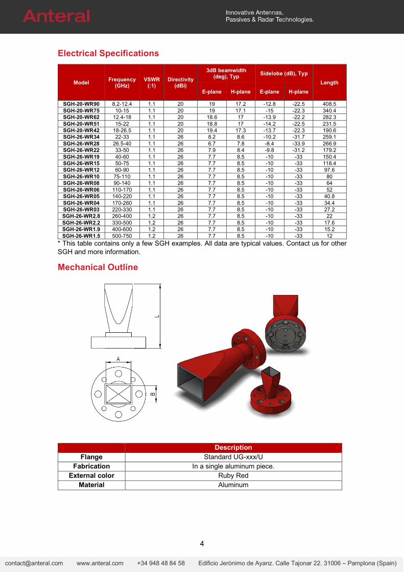
SGH-20-WR90 8.2-12.4 1.1 20 19 17.2 -12.8 -22.5 408.5 SGH-20-WR75 10-15 1.1 20 19 17.1 -15 -22.3 340.4 SGH-20-WR62 12.4-18 1.1 20 18.6 17 -13.9 -22.2 282.3 SGH-20-WR51 15-22 1.1 20 18.8 17 -14.2 -22.5 231.5 SGH-20-WR42 18-26.5 1.1 20 19.4 17.3 -13.7 -22.3 190.6 SGH-26-WR34 22-33 1.1 26 8.2 8.6 -10.2 -31.7 259.1 SGH-26-WR28 26.5-40 1.1 26 6.7 7.8 -8.4 -33.9 266.9 SGH-26-WR22 33-50 1.1 26 7.9 8.4 -9.8 -31.2 179.2 SGH-26-WR19 40-60 1.1 26 7.7 8.5 -10 -33 150.4 SGH-26-WR15 50-75 1.1 26 7.7 8.5 -10 -33 118.4 SGH-26-WR12 60-90 1.1 26 7.7 8.5 -10 -33 97.6 SGH-26-WR10 75-110 1.1 26 7.7 8.5 -10 -33 80 SGH-26-WR08 90-140 1.1 26 7.7 8.5 -10 -33 64 SGH-26-WR06 110-170 1.1 26 7.7 8.5 -10 -33 52 SGH-26-WR05 140-220 1.1 26 7.7 8.5 -10 -33 40.8 SGH-26-WR04 170-260 1.1 26 7.7 8.5 -10 -33 34.4 SGH-26-WR03 220-330 1.1 26 7.7 8.5 -10 -33 27.2 SGH-26-WR2.8 260-400 1.2 26 7.7 8.5 -10 -33 22 SGH-26-WR2.2 330-500 1.2 26 7.7 8.5 -10 -33 17.6 SGH-26-WR1.9 400-600 1.2 26 7.7 8.5 -10 -33 15.2 SGH-26-WR1.5 500-750 1.2 26 7.7 8.5 -10 -33 12
* This table contains only a few SGH examples. All data are typical values. Contact us for other SGH and more information.
Mechanical Outline
Description Flange Standard UG-xxx/U
Fabrication In a single aluminum piece. External color Ruby Red
Material Aluminum
5
[email protected] www.anteral.com +34 948 48 84 58 Edificio Jerónimo de Ayanz. Calle Tajonar 22. 31006 – Pamplona (Spain)
2. Scalar Feed Horn Antenna (SFHA)
Features
High performance feed horns. From 18 to 110 GHz (WR42 to WR10). 10 dBi, 15 dBi, 18 dBi nominal mid-band gain. Low VSWR and sidelobe. Custom specifications can be requested.
Product Description
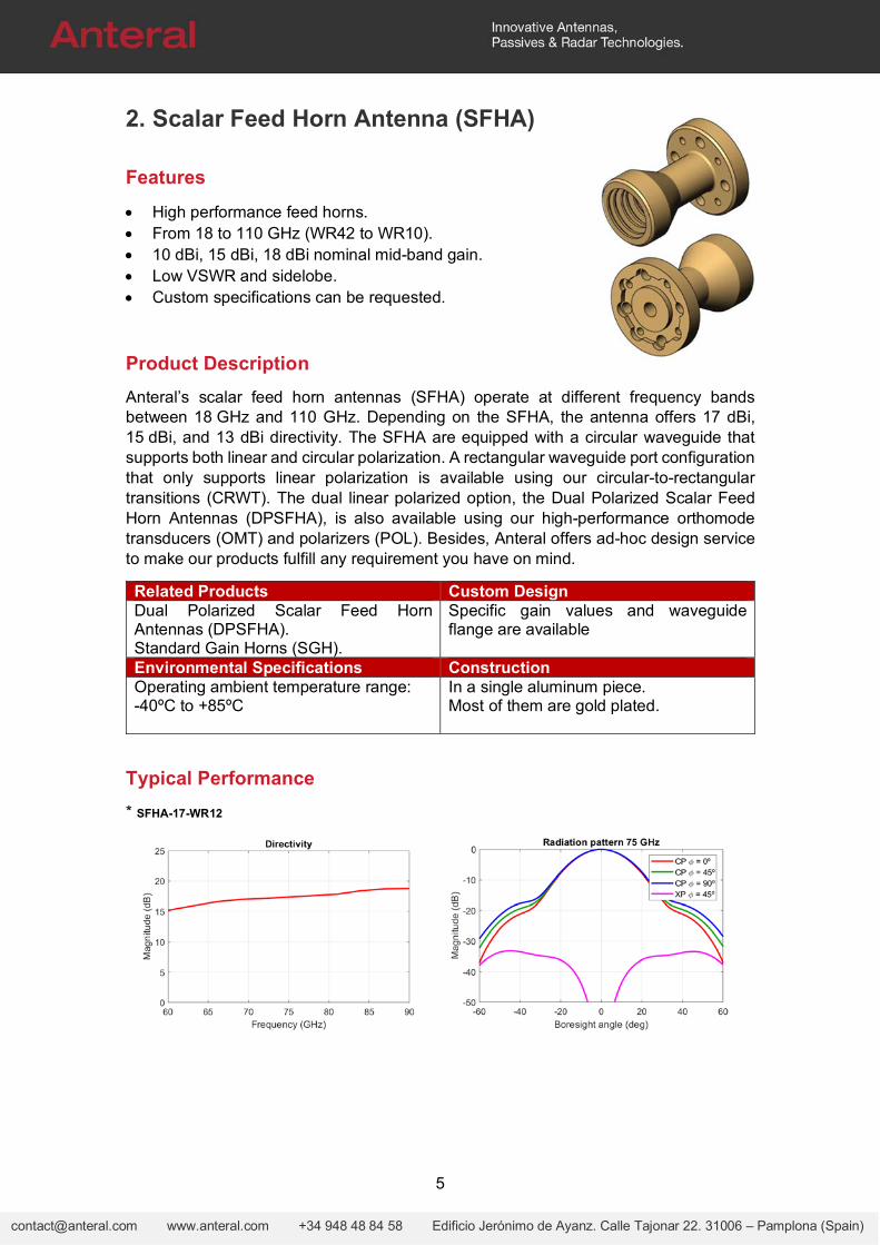
Anteral’s scalar feed horn antennas (SFHA) operate at different frequency bands between 18 GHz and 110 GHz. Depending on the SFHA, the antenna offers 17 dBi, 15 dBi, and 13 dBi directivity. The SFHA are equipped with a circular waveguide that supports both linear and circular polarization. A rectangular waveguide port configuration that only supports linear polarization is available using our circular-to-rectangular transitions (CRWT). The dual linear polarized option, the Dual Polarized Scalar Feed Horn Antennas (DPSFHA), is also available using our high-performance orthomode transducers (OMT) and polarizers (POL). Besides, Anteral offers ad-hoc design service to make our products fulfill any requirement you have on mind.
Related Products Custom DesignDual Polarized Scalar Feed Horn Antennas (DPSFHA). Standard Gain Horns (SGH).
Specific gain values and waveguide flange are available
Environmental Specifications ConstructionOperating ambient temperature range: -40ºC to +85ºC
In a single aluminum piece. Most of them are gold plated.
Typical Performance
* SFHA-17-WR12
6
[email protected] www.anteral.com +34 948 48 84 58 Edificio Jerónimo de Ayanz. Calle Tajonar 22. 31006 – Pamplona (Spain)
Electrical Specifications
Model Frequency
(GHz) VSWR, Typ (:1)
Directivity, Typ (dBi)
3dB beamwidth, Typ (deg)
Sidelobe, Typ (dB) XP (dB) (±10deg)
E-plane H-plane E-plane H-plane
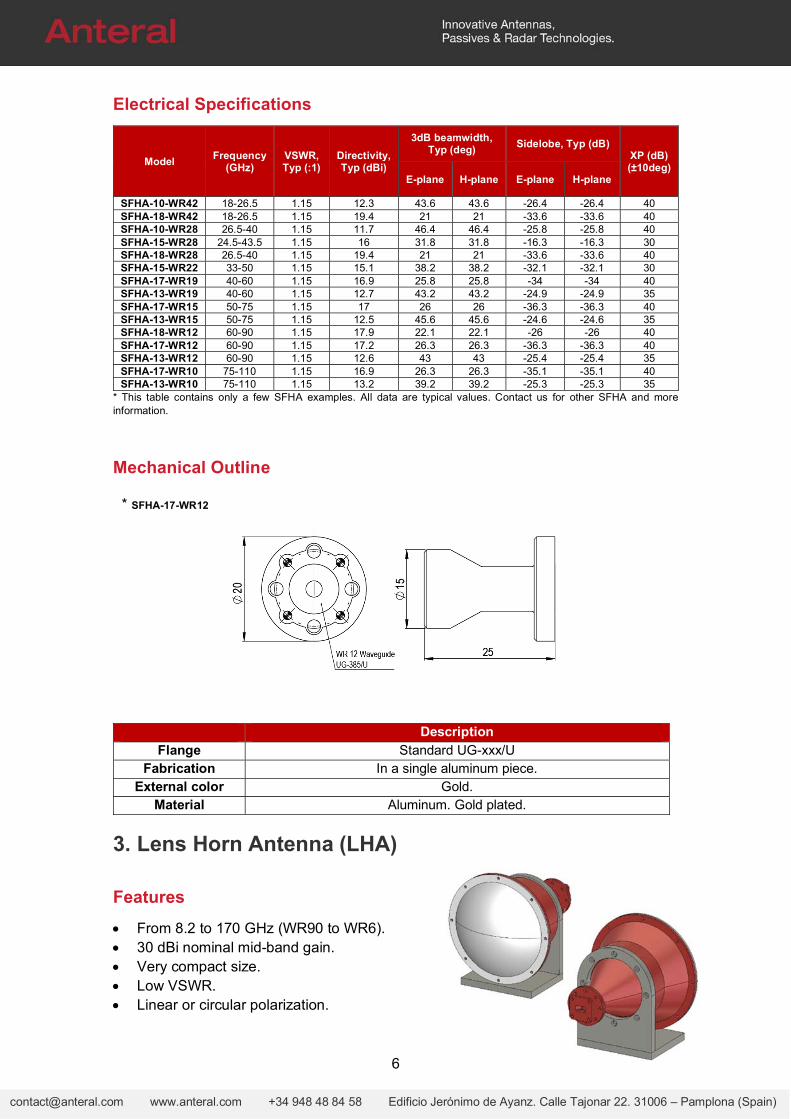
SFHA-10-WR42 18-26.5 1.15 12.3 43.6 43.6 -26.4 -26.4 40 SFHA-18-WR42 18-26.5 1.15 19.4 21 21 -33.6 -33.6 40 SFHA-10-WR28 26.5-40 1.15 11.7 46.4 46.4 -25.8 -25.8 40 SFHA-15-WR28 24.5-43.5 1.15 16 31.8 31.8 -16.3 -16.3 30 SFHA-18-WR28 26.5-40 1.15 19.4 21 21 -33.6 -33.6 40 SFHA-15-WR22 33-50 1.15 15.1 38.2 38.2 -32.1 -32.1 30 SFHA-17-WR19 40-60 1.15 16.9 25.8 25.8 -34 -34 40 SFHA-13-WR19 40-60 1.15 12.7 43.2 43.2 -24.9 -24.9 35 SFHA-17-WR15 50-75 1.15 17 26 26 -36.3 -36.3 40 SFHA-13-WR15 50-75 1.15 12.5 45.6 45.6 -24.6 -24.6 35 SFHA-18-WR12 60-90 1.15 17.9 22.1 22.1 -26 -26 40 SFHA-17-WR12 60-90 1.15 17.2 26.3 26.3 -36.3 -36.3 40 SFHA-13-WR12 60-90 1.15 12.6 43 43 -25.4 -25.4 35 SFHA-17-WR10 75-110 1.15 16.9 26.3 26.3 -35.1 -35.1 40 SFHA-13-WR10 75-110 1.15 13.2 39.2 39.2 -25.3 -25.3 35
* This table contains only a few SFHA examples. All data are typical values. Contact us for other SFHA and more information.
Mechanical Outline
Description Flange Standard UG-xxx/U
Fabrication In a single aluminum piece. External color Gold.
Material Aluminum. Gold plated.
3. Lens Horn Antenna (LHA)
Features
From 8.2 to 170 GHz (WR90 to WR6). 30 dBi nominal mid-band gain. Very compact size. Low VSWR. Linear or circular polarization.
* SFHA-17-WR12
7
[email protected] www.anteral.com +34 948 48 84 58 Edificio Jerónimo de Ayanz. Calle Tajonar 22. 31006 – Pamplona (Spain)
Custom specifications can be requested.
Product Description
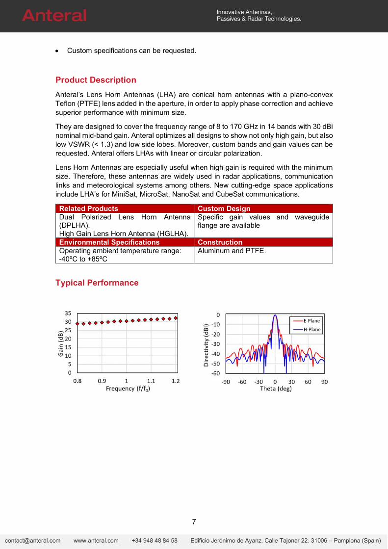
Anteral’s Lens Horn Antennas (LHA) are conical horn antennas with a plano-convex Teflon (PTFE) lens added in the aperture, in order to apply phase correction and achieve superior performance with minimum size.
They are designed to cover the frequency range of 8 to 170 GHz in 14 bands with 30 dBi nominal mid-band gain. Anteral optimizes all designs to show not only high gain, but also low VSWR (< 1.3) and low side lobes. Moreover, custom bands and gain values can be requested. Anteral offers LHAs with linear or circular polarization.
Lens Horn Antennas are especially useful when high gain is required with the minimum size. Therefore, these antennas are widely used in radar applications, communication links and meteorological systems among others. New cutting-edge space applications include LHA’s for MiniSat, MicroSat, NanoSat and CubeSat communications.
Related Products Custom DesignDual Polarized Lens Horn Antenna (DPLHA). High Gain Lens Horn Antenna (HGLHA).
Specific gain values and waveguide flange are available
Environmental Specifications ConstructionOperating ambient temperature range: -40ºC to +85ºC
Aluminum and PTFE.
Typical Performance
8
[email protected] www.anteral.com +34 948 48 84 58 Edificio Jerónimo de Ayanz. Calle Tajonar 22. 31006 – Pamplona (Spain)
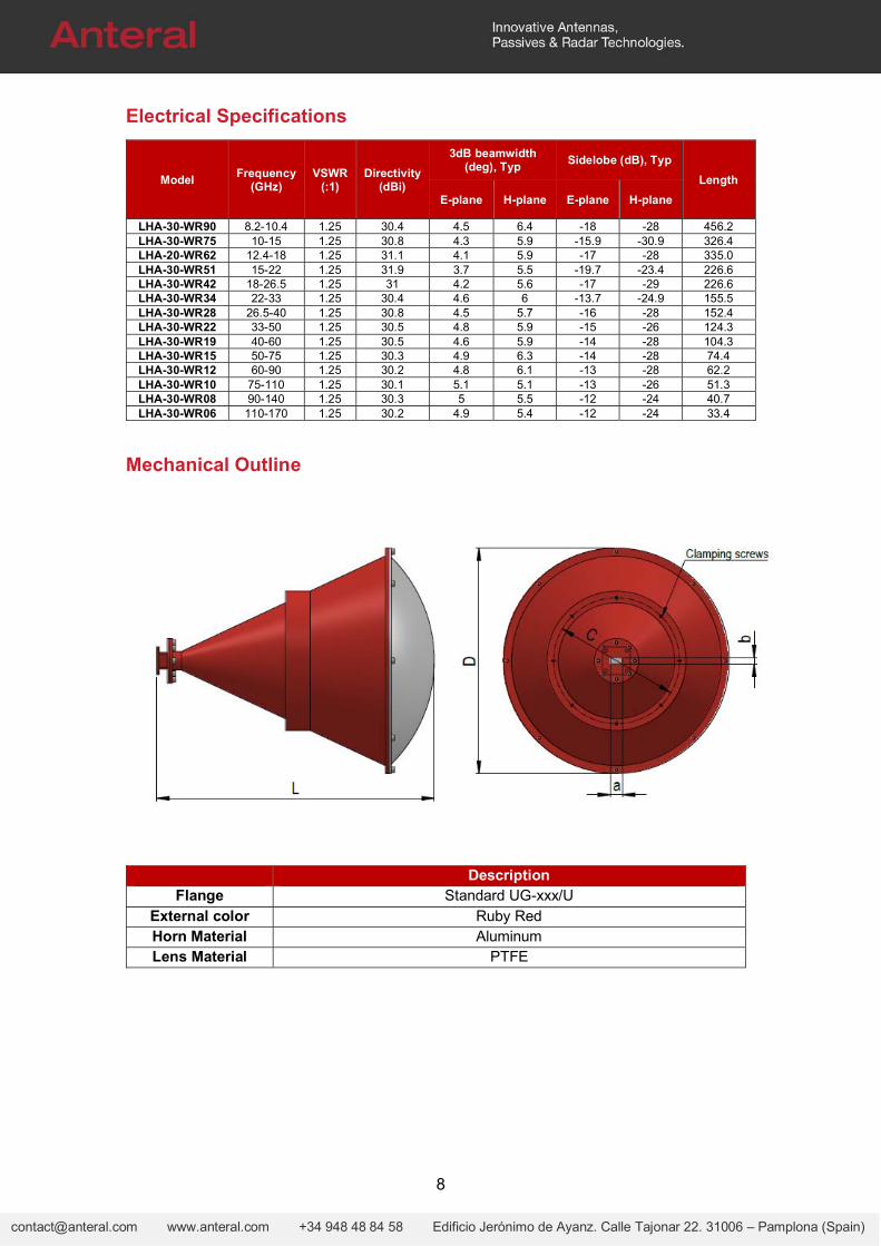
Electrical Specifications
Model Frequency
(GHz) VSWR
(:1) Directivity
(dBi)
3dB beamwidth (deg), Typ
Sidelobe (dB), Typ
Length
E-plane H-plane E-plane H-plane
LHA-30-WR90 8.2-10.4 1.25 30.4 4.5 6.4 -18 -28 456.2 LHA-30-WR75 10-15 1.25 30.8 4.3 5.9 -15.9 -30.9 326.4 LHA-20-WR62 12.4-18 1.25 31.1 4.1 5.9 -17 -28 335.0 LHA-30-WR51 15-22 1.25 31.9 3.7 5.5 -19.7 -23.4 226.6 LHA-30-WR42 18-26.5 1.25 31 4.2 5.6 -17 -29 226.6 LHA-30-WR34 22-33 1.25 30.4 4.6 6 -13.7 -24.9 155.5 LHA-30-WR28 26.5-40 1.25 30.8 4.5 5.7 -16 -28 152.4 LHA-30-WR22 33-50 1.25 30.5 4.8 5.9 -15 -26 124.3 LHA-30-WR19 40-60 1.25 30.5 4.6 5.9 -14 -28 104.3 LHA-30-WR15 50-75 1.25 30.3 4.9 6.3 -14 -28 74.4 LHA-30-WR12 60-90 1.25 30.2 4.8 6.1 -13 -28 62.2 LHA-30-WR10 75-110 1.25 30.1 5.1 5.1 -13 -26 51.3 LHA-30-WR08 90-140 1.25 30.3 5 5.5 -12 -24 40.7 LHA-30-WR06 110-170 1.25 30.2 4.9 5.4 -12 -24 33.4
Mechanical Outline
Description Flange Standard UG-xxx/U
External color Ruby Red Horn Material Aluminum Lens Material PTFE
9
[email protected] www.anteral.com +34 948 48 84 58 Edificio Jerónimo de Ayanz. Calle Tajonar 22. 31006 – Pamplona (Spain)
4. Focusing Lens Horn Antenna (LHA-F)
Features
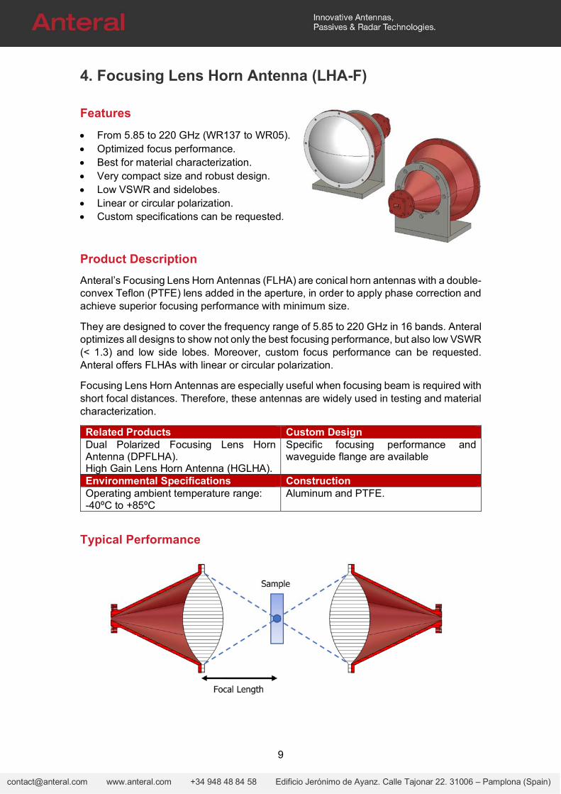
From 5.85 to 220 GHz (WR137 to WR05). Optimized focus performance. Best for material characterization. Very compact size and robust design. Low VSWR and sidelobes. Linear or circular polarization. Custom specifications can be requested.
Product Description
Anteral’s Focusing Lens Horn Antennas (FLHA) are conical horn antennas with a double-convex Teflon (PTFE) lens added in the aperture, in order to apply phase correction and achieve superior focusing performance with minimum size.
They are designed to cover the frequency range of 5.85 to 220 GHz in 16 bands. Anteral optimizes all designs to show not only the best focusing performance, but also low VSWR (< 1.3) and low side lobes. Moreover, custom focus performance can be requested. Anteral offers FLHAs with linear or circular polarization.
Focusing Lens Horn Antennas are especially useful when focusing beam is required with short focal distances. Therefore, these antennas are widely used in testing and material characterization.
Related Products Custom DesignDual Polarized Focusing Lens Horn Antenna (DPFLHA). High Gain Lens Horn Antenna (HGLHA).
Specific focusing performance and waveguide flange are available
Environmental Specifications ConstructionOperating ambient temperature range: -40ºC to +85ºC
Aluminum and PTFE.
Typical Performance
10
[email protected] www.anteral.com +34 948 48 84 58 Edificio Jerónimo de Ayanz. Calle Tajonar 22. 31006 – Pamplona (Spain)
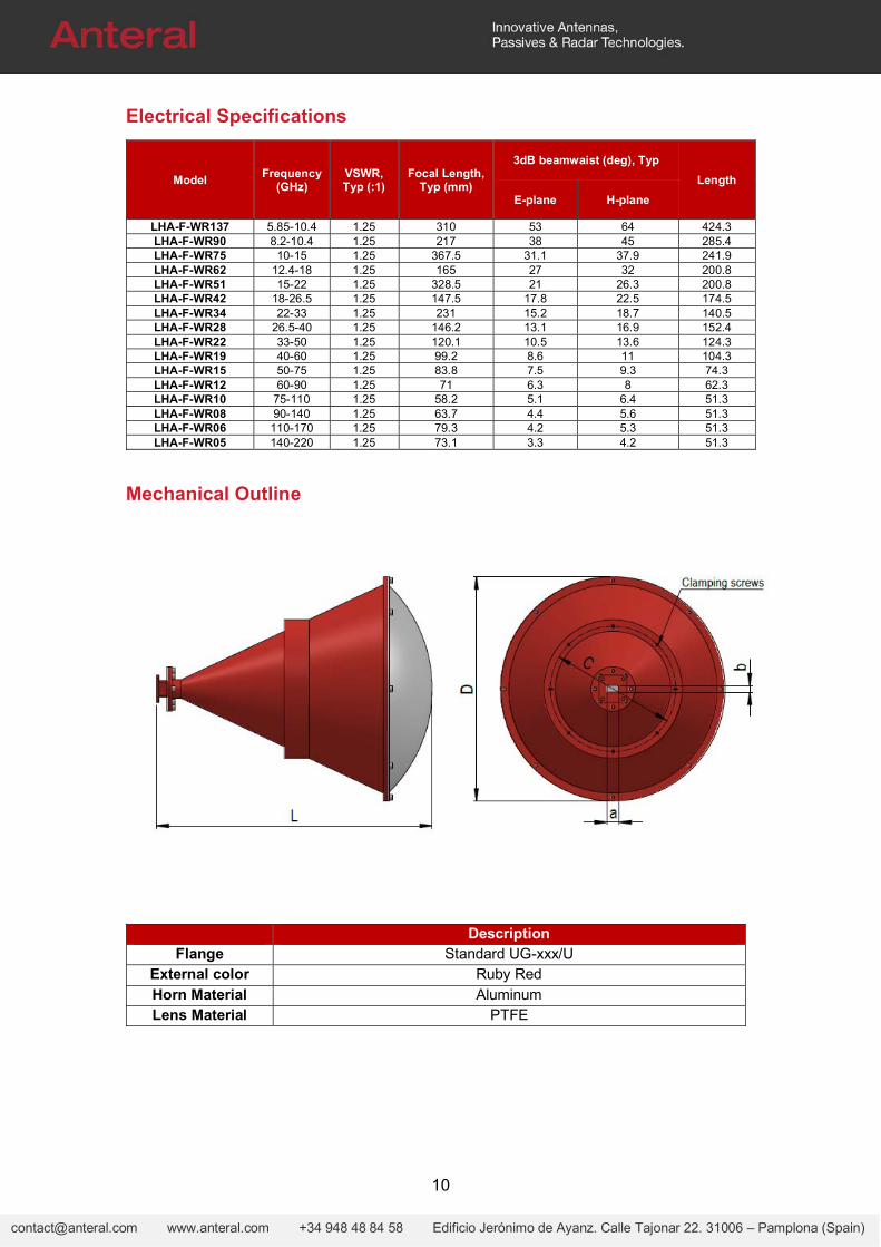
Electrical Specifications
Model Frequency
(GHz) VSWR, Typ (:1)
Focal Length, Typ (mm)
3dB beamwaist (deg), Typ
Length
E-plane H-plane
LHA-F-WR137 5.85-10.4 1.25 310 53 64 424.3 LHA-F-WR90 8.2-10.4 1.25 217 38 45 285.4 LHA-F-WR75 10-15 1.25 367.5 31.1 37.9 241.9 LHA-F-WR62 12.4-18 1.25 165 27 32 200.8 LHA-F-WR51 15-22 1.25 328.5 21 26.3 200.8 LHA-F-WR42 18-26.5 1.25 147.5 17.8 22.5 174.5 LHA-F-WR34 22-33 1.25 231 15.2 18.7 140.5 LHA-F-WR28 26.5-40 1.25 146.2 13.1 16.9 152.4 LHA-F-WR22 33-50 1.25 120.1 10.5 13.6 124.3 LHA-F-WR19 40-60 1.25 99.2 8.6 11 104.3 LHA-F-WR15 50-75 1.25 83.8 7.5 9.3 74.3 LHA-F-WR12 60-90 1.25 71 6.3 8 62.3 LHA-F-WR10 75-110 1.25 58.2 5.1 6.4 51.3 LHA-F-WR08 90-140 1.25 63.7 4.4 5.6 51.3 LHA-F-WR06 110-170 1.25 79.3 4.2 5.3 51.3 LHA-F-WR05 140-220 1.25 73.1 3.3 4.2 51.3
Mechanical Outline
Description Flange Standard UG-xxx/U
External color Ruby Red Horn Material Aluminum Lens Material PTFE
11
[email protected] www.anteral.com +34 948 48 84 58 Edificio Jerónimo de Ayanz. Calle Tajonar 22. 31006 – Pamplona (Spain)
5. High-Gain Lens Horn Antenna (HGLHA)
Features
From 110 to 600 GHz (WR6 to WR1.9). 40 dBi nominal mid-band gain. Very compact size and robust design. Low VSWR and sidelobes. Linear or circular polarization. Custom specifications can be requested.
Product Description
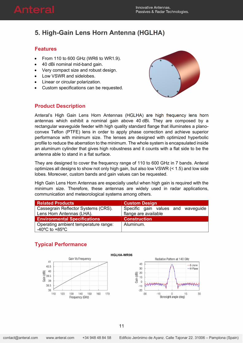
Anteral’s High Gain Lens Horn Antennas (HGLHA) are high frequency lens horn antennas which exhibit a nominal gain above 40 dBi. They are composed by a rectangular waveguide feeder with high quality standard flange that illuminates a plano-convex Teflon (PTFE) lens in order to apply phase correction and achieve superior performance with minimum size. The lenses are designed with optimized hyperbolic profile to reduce the aberration to the minimum. The whole system is encapsulated inside an aluminum cylinder that gives high robustness and it counts with a flat side to be the antenna able to stand in a flat surface.
They are designed to cover the frequency range of 110 to 600 GHz in 7 bands. Anteral optimizes all designs to show not only high gain, but also low VSWR (< 1.5) and low side lobes. Moreover, custom bands and gain values can be requested.
High Gain Lens Horn Antennas are especially useful when high gain is required with the minimum size. Therefore, these antennas are widely used in radar applications, communication and meteorological systems among others.
Related Products Custom DesignCassegrain Reflector Systems (CRS). Lens Horn Antennas (LHA).
Specific gain values and waveguide flange are available
Environmental Specifications ConstructionOperating ambient temperature range: -40ºC to +85ºC
Aluminum.
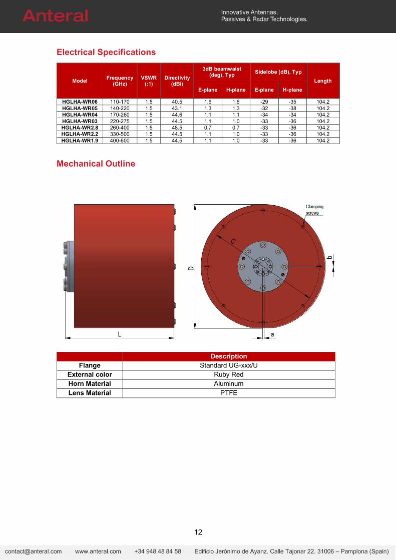
Typical Performance
HGLHA-WR06
12
[email protected] www.anteral.com +34 948 48 84 58 Edificio Jerónimo de Ayanz. Calle Tajonar 22. 31006 – Pamplona (Spain)
Electrical Specifications
Model Frequency
(GHz) VSWR
(:1) Directivity
(dBi)
3dB beamwaist (deg), Typ
Sidelobe (dB), Typ
Length
E-plane H-plane E-plane H-plane
HGLHA-WR06 110-170 1.5 40.5 1.6 1.6 -29 -35 104.2 HGLHA-WR05 140-220 1.5 43.1 1.3 1.3 -32 -38 104.2 HGLHA-WR04 170-260 1.5 44.6 1.1 1.1 -34 -34 104.2 HGLHA-WR03 220-275 1.5 44.5 1.1 1.0 -33 -36 104.2 HGLHA-WR2.8 260-400 1.5 48.5 0.7 0.7 -33 -36 104.2 HGLHA-WR2.2 330-500 1.5 44.5 1.1 1.0 -33 -36 104.2 HGLHA-WR1.9 400-600 1.5 44.5 1.1 1.0 -33 -36 104.2
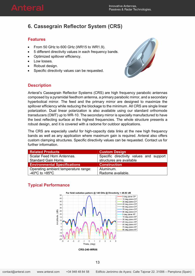
Mechanical Outline
Description
Flange Standard UG-xxx/U External color Ruby Red Horn Material Aluminum Lens Material PTFE
13
[email protected] www.anteral.com +34 948 48 84 58 Edificio Jerónimo de Ayanz. Calle Tajonar 22. 31006 – Pamplona (Spain)
6. Cassegrain Reflector System (CRS)
Features
From 50 GHz to 600 GHz (WR15 to WR1.9). 5 different directivity values in each frequency bands. Optimized spillover efficiency. Low losses. Robust design. Specific directivity values can be requested.
Description
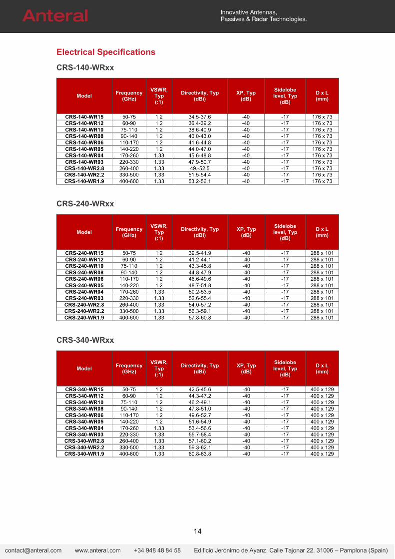
Anteral’s Cassegrain Reflector Systems (CRS) are high frequency parabolic antennas composed by a pyramidal feedhorn antenna, a primary parabolic mirror, and a secondary hyperbolical mirror. The feed and the primary mirror are designed to maximize the spillover efficiency while reducing the blockage to the minimum. All CRS are single linear polarization. Dual linear polarization is also available using our standard orthomode transducers (OMT) up to WR-10. The secondary mirror is specially manufactured to have the best reflecting surface at the highest frequencies. The whole structure presents a robust design, and it is covered with a radome for outdoor applications.
The CRS are especially useful for high-capacity data links at the new high frequency bands as well as any application where maximum gain is required. Anteral also offers custom clamping structures. Specific directivity values can be requested. Contact us for further information.
Related Products Custom DesignScalar Feed Horn Antennas. Standard Gain Horns.
Specific directivity values and support structures are available
Environmental Specifications ConstructionOperating ambient temperature range: -40ºC to +85ºC
Aluminum. Radome available.
Typical Performance
CRS-240-WR06
14
[email protected] www.anteral.com +34 948 48 84 58 Edificio Jerónimo de Ayanz. Calle Tajonar 22. 31006 – Pamplona (Spain)
Electrical Specifications
CRS-140-WRxx
Model Frequency
(GHz)
VSWR, Typ (:1)
Directivity, Typ (dBi)
XP, Typ (dB)
Sidelobe level, Typ
(dB)
D x L (mm)
CRS-140-WR15 50-75 1.2 34.5-37.6 -40 -17 176 x 73 CRS-140-WR12 60-90 1.2 36.4-39.2 -40 -17 176 x 73 CRS-140-WR10 75-110 1.2 38.6-40.9 -40 -17 176 x 73 CRS-140-WR08 90-140 1.2 40.0-43.0 -40 -17 176 x 73 CRS-140-WR06 110-170 1.2 41.6-44.8 -40 -17 176 x 73 CRS-140-WR05 140-220 1.2 44.0-47.0 -40 -17 176 x 73 CRS-140-WR04 170-260 1.33 45.6-48.8 -40 -17 176 x 73 CRS-140-WR03 220-330 1.33 47.9-50.7 -40 -17 176 x 73 CRS-140-WR2.8 260-400 1.33 49.-52.5 -40 -17 176 x 73 CRS-140-WR2.2 330-500 1.33 51.5-54.4 -40 -17 176 x 73 CRS-140-WR1.9 400-600 1.33 53.2-56.1 -40 -17 176 x 73
CRS-240-WRxx
Model Frequency
(GHz)
VSWR, Typ (:1)
Directivity, Typ (dBi)
XP, Typ (dB)
Sidelobe level, Typ
(dB)
D x L (mm)
CRS-240-WR15 50-75 1.2 39.5-41.9 -40 -17 288 x 101 CRS-240-WR12 60-90 1.2 41.2-44.1 -40 -17 288 x 101 CRS-240-WR10 75-110 1.2 43.3-45.8 -40 -17 288 x 101 CRS-240-WR08 90-140 1.2 44.8-47.9 -40 -17 288 x 101 CRS-240-WR06 110-170 1.2 46.6-49.6 -40 -17 288 x 101 CRS-240-WR05 140-220 1.2 48.7-51.8 -40 -17 288 x 101 CRS-240-WR04 170-260 1.33 50.2-53.5 -40 -17 288 x 101 CRS-240-WR03 220-330 1.33 52.6-55.4 -40 -17 288 x 101 CRS-240-WR2.8 260-400 1.33 54.0-57.2 -40 -17 288 x 101 CRS-240-WR2.2 330-500 1.33 56.3-59.1 -40 -17 288 x 101 CRS-240-WR1.9 400-600 1.33 57.8-60.8 -40 -17 288 x 101
CRS-340-WRxx
Model Frequency
(GHz)
VSWR, Typ (:1)
Directivity, Typ (dBi)
XP, Typ (dB)
Sidelobe level, Typ
(dB)
D x L (mm)
CRS-340-WR15 50-75 1.2 42.5-45.6 -40 -17 400 x 129 CRS-340-WR12 60-90 1.2 44.3-47.2 -40 -17 400 x 129 CRS-340-WR10 75-110 1.2 46.2-49.1 -40 -17 400 x 129 CRS-340-WR08 90-140 1.2 47.8-51.0 -40 -17 400 x 129 CRS-340-WR06 110-170 1.2 49.6-52.7 -40 -17 400 x 129 CRS-340-WR05 140-220 1.2 51.6-54.9 -40 -17 400 x 129 CRS-340-WR04 170-260 1.33 53.4-56.6 -40 -17 400 x 129 CRS-340-WR03 220-330 1.33 55.7-58.4 -40 -17 400 x 129 CRS-340-WR2.8 260-400 1.33 57.1-60.2 -40 -17 400 x 129 CRS-340-WR2.2 330-500 1.33 59.3-62.1 -40 -17 400 x 129 CRS-340-WR1.9 400-600 1.33 60.8-63.8 -40 -17 400 x 129
15
[email protected] www.anteral.com +34 948 48 84 58 Edificio Jerónimo de Ayanz. Calle Tajonar 22. 31006 – Pamplona (Spain)
CRS-440-WRxx
Model Frequency
(GHz)
VSWR, Typ (:1)
Directivity, Typ (dBi)
XP, Typ (dB)
Sidelobe level, Typ
(dB)
D x L (mm)
CRS-440-WR15 50-75 1.2 44.6-47.8 -40 -17 500 x 154 CRS-440-WR12 60-90 1.2 46.2-49.6 -40 -17 500 x 154 CRS-440-WR10 75-110 1.2 48.7-51.5 -40 -17 500 x 154 CRS-440-WR08 90-140 1.2 50.0-53.5 -40 -17 500 x 154 CRS-440-WR06 110-170 1.2 51.8-55.2 -40 -17 500 x 154 CRS-440-WR05 140-220 1.2 53.9-57.4 -40 -17 500 x 154 CRS-440-WR04 170-260 1.33 55.6-59.1 -40 -17 500 x 154 CRS-440-WR03 220-330 1.33 57.9-60.9 -40 -17 500 x 154 CRS-440-WR2.8 260-400 1.33 59.4-62.7 -40 -17 500 x 154 CRS-440-WR2.2 330-500 1.33 61.5-64.7 -40 -17 500 x 154 CRS-440-WR1.9 400-600 1.33 63.1-66.3 -40 -17 500 x 154
CRS-520-WRxx
Model Frequency
(GHz)
VSWR, Typ (:1)
Directivity, Typ (dBi)
XP, Typ (dB)
Sidelobe level, Typ
(dB)
D x L (mm)
CRS-520-WR15 50-75 1.2 46.4-49.4 -40 -17 580 x 174 CRS-520-WR12 60-90 1.2 47.9-51.2 -40 -17 580 x 174 CRS-520-WR10 75-110 1.2 50.0-53.0 -40 -17 580 x 174 CRS-520-WR08 90-140 1.2 51.5-55.0 -40 -17 580 x 174 CRS-520-WR06 110-170 1.2 53.2-56.7 -40 -17 580 x 174 CRS-520-WR05 140-220 1.2 55.3-58.9 -40 -17 580 x 174 CRS-520-WR04 170-260 1.33 57.0-60.6 -40 -17 580 x 174 CRS-520-WR03 220-330 1.33 59.3-62.4 -40 -17 580 x 174 CRS-520-WR2.8 260-400 1.33 60.8-64.2 -40 -17 580 x 174 CRS-520-WR2.2 330-500 1.33 62.9-66.1 -40 -17 580 x 174 CRS-520-WR1.9 400-600 1.33 64.5-67.8 -40 -17 580 x 174
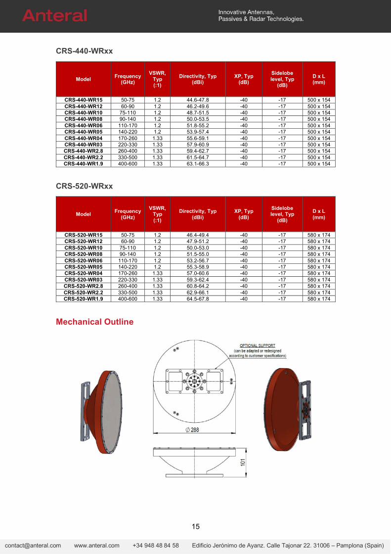
Mechanical Outline
16
[email protected] www.anteral.com +34 948 48 84 58 Edificio Jerónimo de Ayanz. Calle Tajonar 22. 31006 – Pamplona (Spain)
7. Trihedral Corner Reflectors (TTCR)
Features
8.4 GHz to 300 GHz available High directivity and gain. Low cost and simple installation. Wide range of available beamwidths and reflector sizes Specific performance can be requested.
Product Description
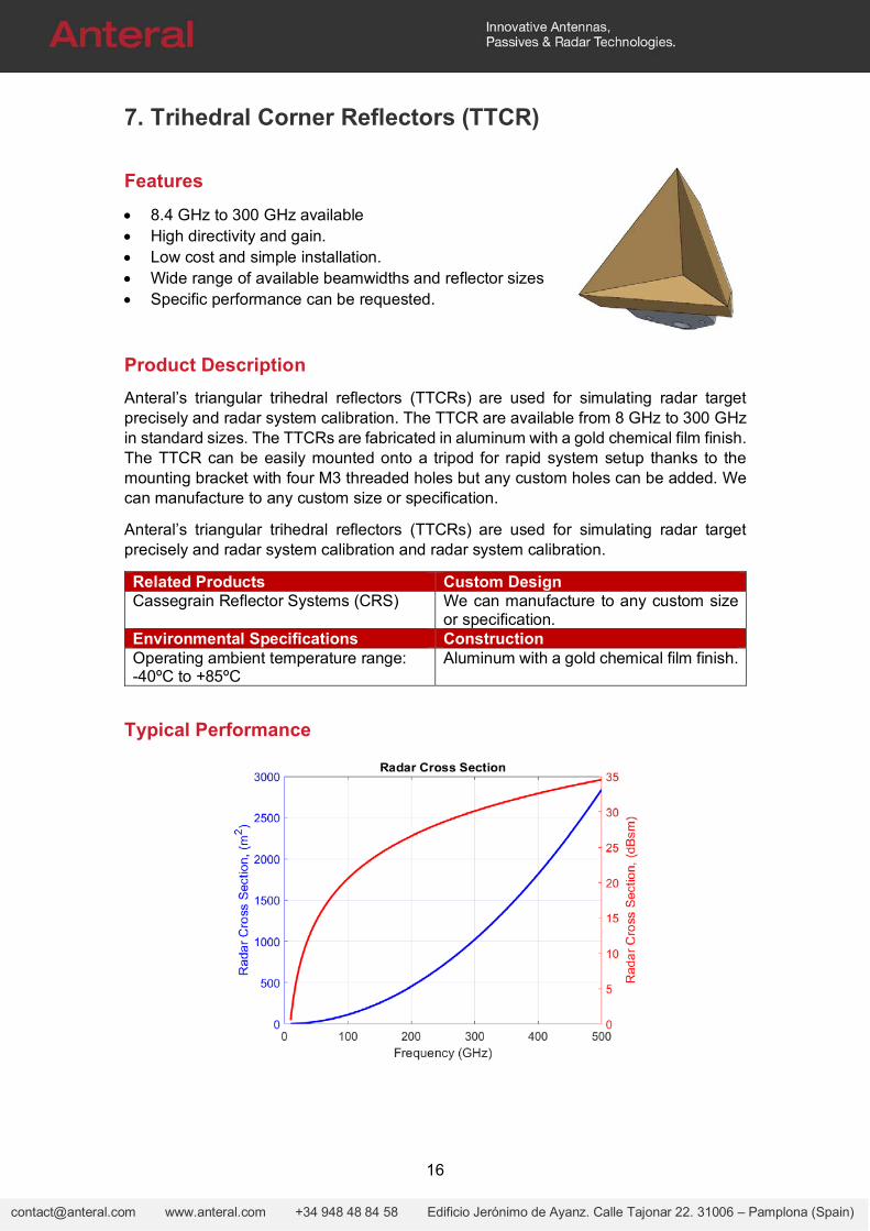
Anteral’s triangular trihedral reflectors (TTCRs) are used for simulating radar target precisely and radar system calibration. The TTCR are available from 8 GHz to 300 GHz in standard sizes. The TTCRs are fabricated in aluminum with a gold chemical film finish. The TTCR can be easily mounted onto a tripod for rapid system setup thanks to the mounting bracket with four M3 threaded holes but any custom holes can be added. We can manufacture to any custom size or specification.
Anteral’s triangular trihedral reflectors (TTCRs) are used for simulating radar target precisely and radar system calibration and radar system calibration.
Related Products Custom DesignCassegrain Reflector Systems (CRS) We can manufacture to any custom size
or specification. Environmental Specifications ConstructionOperating ambient temperature range: -40ºC to +85ºC
Aluminum with a gold chemical film finish.
Typical Performance
17
[email protected] www.anteral.com +34 948 48 84 58 Edificio Jerónimo de Ayanz. Calle Tajonar 22. 31006 – Pamplona (Spain)
8. Near Field Probes (NFP)
Features
From 8.2 to 750 GHz (WR90 to WR1.5). Sharp edged. Single piece aluminum probes. Long-length probes.
Product Description
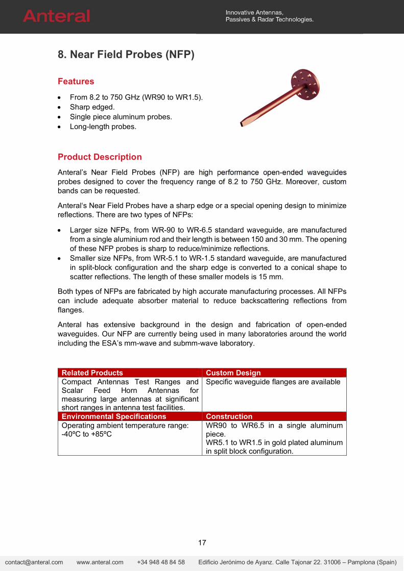
Anteral’s Near Field Probes (NFP) are high performance open-ended waveguides probes designed to cover the frequency range of 8.2 to 750 GHz. Moreover, custom bands can be requested.
Anteral‘s Near Field Probes have a sharp edge or a special opening design to minimize reflections. There are two types of NFPs:
Larger size NFPs, from WR-90 to WR-6.5 standard waveguide, are manufactured from a single aluminium rod and their length is between 150 and 30 mm. The opening of these NFP probes is sharp to reduce/minimize reflections.
Smaller size NFPs, from WR-5.1 to WR-1.5 standard waveguide, are manufactured in split-block configuration and the sharp edge is converted to a conical shape to scatter reflections. The length of these smaller models is 15 mm.
Both types of NFPs are fabricated by high accurate manufacturing processes. All NFPs can include adequate absorber material to reduce backscattering reflections from flanges.
Anteral has extensive background in the design and fabrication of open-ended waveguides. Our NFP are currently being used in many laboratories around the world including the ESA’s mm-wave and submm-wave laboratory.
Related Products Custom DesignCompact Antennas Test Ranges and Scalar Feed Horn Antennas for measuring large antennas at significant short ranges in antenna test facilities.
Specific waveguide flanges are available
Environmental Specifications ConstructionOperating ambient temperature range: -40ºC to +85ºC
WR90 to WR6.5 in a single aluminum piece. WR5.1 to WR1.5 in gold plated aluminum in split block configuration.
18
[email protected] www.anteral.com +34 948 48 84 58 Edificio Jerónimo de Ayanz. Calle Tajonar 22. 31006 – Pamplona (Spain)
Electrical Specifications
Model Frequency (GHz) VSWR, Typ (:1) Directivity (dB) Length
NFP‐WR90 8.2-10.4 1.58 7.5 150 NFP‐WR75 10-15 1.58 7.5 150 NFP‐WR62 12.4-18 1.58 7.5 150 NFP‐WR51 15-22 1.58 7.5 150 NFP‐WR42 18-26.5 1.58 7.5 150 NFP‐WR34 22-33 1.58 7.5 100 NFP‐WR28 26.5-40 1.58 7.5 100 NFP‐WR22 33-50 1.58 7.5 60 NFP‐WR19 40-60 1.58 7.5 60 NFP‐WR15 50-75 1.58 7.5 40 NFP‐WR12 60-90 1.58 7.5 40 NFP‐WR10 75-110 1.58 7.5 40 NFP‐WR08 90-140 1.58 7.5 30 NFP‐WR06 110-170 1.58 7.5 30 NFP‐WR05 140-220 1.58 7.5 15 NFP‐WR04 170-260 1.58 7.5 15 NFP‐WR03 220-330 1.58 7.5 15 NFP‐WR2.8 260-400 1.58 7.5 15 NFP‐WR2.2 330-500 1.58 7.5 15 NFP‐WR1.9 400-600 1.58 7.5 15 NFP‐WR1.5 500-750 1.58 7.5 15
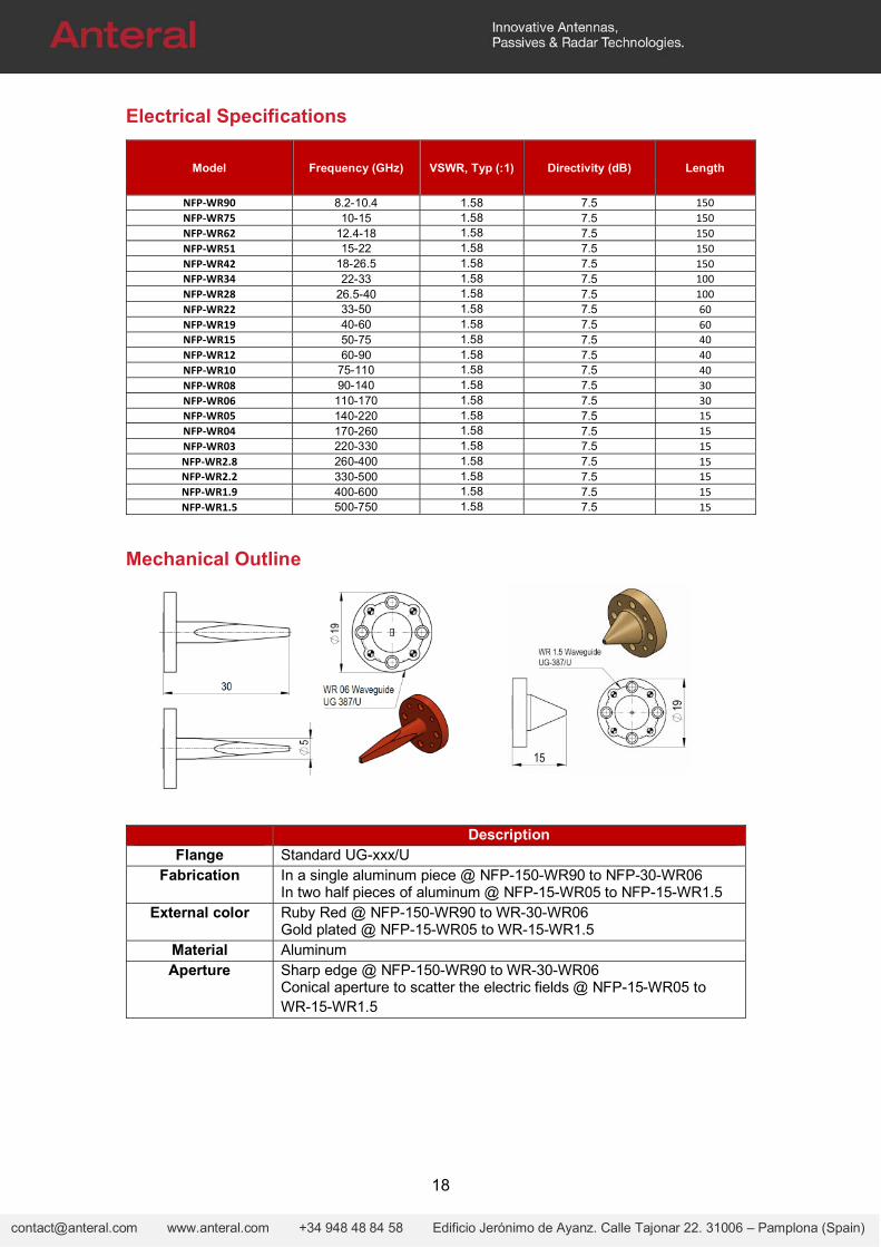
Mechanical Outline
Description Flange Standard UG-xxx/U
Fabrication In a single aluminum piece @ NFP-150-WR90 to NFP-30-WR06 In two half pieces of aluminum @ NFP-15-WR05 to NFP-15-WR1.5
External color Ruby Red @ NFP-150-WR90 to WR-30-WR06 Gold plated @ NFP-15-WR05 to WR-15-WR1.5
Material Aluminum Aperture Sharp edge @ NFP-150-WR90 to WR-30-WR06
Conical aperture to scatter the electric fields @ NFP-15-WR05 to WR-15-WR1.5
19
[email protected] www.anteral.com +34 948 48 84 58 Edificio Jerónimo de Ayanz. Calle Tajonar 22. 31006 – Pamplona (Spain)
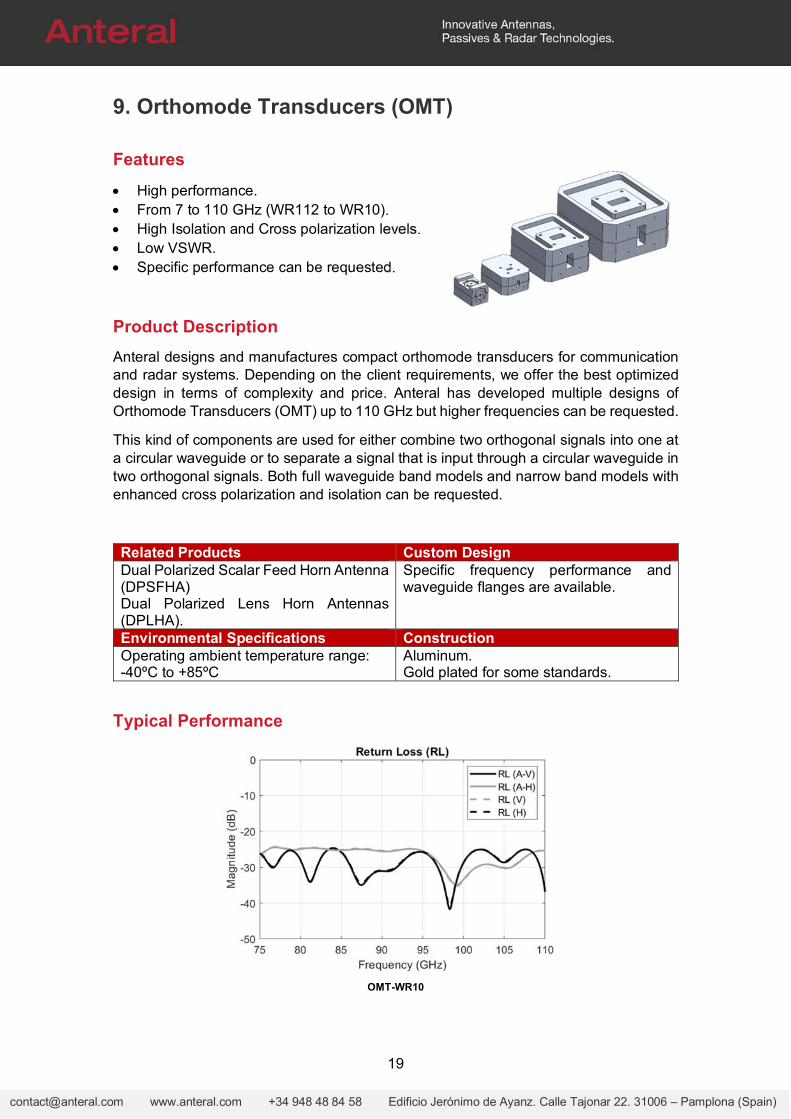
9. Orthomode Transducers (OMT)
Features
High performance. From 7 to 110 GHz (WR112 to WR10). High Isolation and Cross polarization levels. Low VSWR. Specific performance can be requested.
Product Description
Anteral designs and manufactures compact orthomode transducers for communication and radar systems. Depending on the client requirements, we offer the best optimized design in terms of complexity and price. Anteral has developed multiple designs of Orthomode Transducers (OMT) up to 110 GHz but higher frequencies can be requested.
This kind of components are used for either combine two orthogonal signals into one at a circular waveguide or to separate a signal that is input through a circular waveguide in two orthogonal signals. Both full waveguide band models and narrow band models with enhanced cross polarization and isolation can be requested.
Related Products Custom DesignDual Polarized Scalar Feed Horn Antenna (DPSFHA) Dual Polarized Lens Horn Antennas (DPLHA).
Specific frequency performance and waveguide flanges are available.
Environmental Specifications ConstructionOperating ambient temperature range: -40ºC to +85ºC
Aluminum. Gold plated for some standards.
Typical Performance
OMT-WR10
20
[email protected] www.anteral.com +34 948 48 84 58 Edificio Jerónimo de Ayanz. Calle Tajonar 22. 31006 – Pamplona (Spain)
Electrical Specifications
Model Frequency
(GHz) VSWR, Typ (:1)
Insertion Loss, Typ
(dB)
Isolation, Typ (dB)
XP, Typ (dB)
Length (mm)
OMT-WR112-01 7.0-10.2 1.1 0.2 45 45 108.5 OMT-WR90-01 8.2-10.4 1.1 0.2 45 45 99.5 OMT-WR75-01 10-15 1.1 0.2 45 45 85.0 OMT-WR62-01 12.4-18 1.1 0.2 40 40 70.0 OMT-WR51-01 15-22 1.1 0.2 40 40 95.0 OMT-WR42-01 18-26.5 1.15 0.2 40 40 76.2 OMT-WR34-01 22-33 1.15 0.2 40 40 69.2 OMT-WR28-01 26.5-40 1.15 0.3 35 35 61.4 OMT-WR28-02 24.5-43.5 1.15 0.3 35 35 45.4 OMT-WR22-01 33-50 1.15 0.3 35 35 47.5 OMT-WR19-01 40-60 1.15 0.3 35 35 44.5 OMT-WR15-01 50-75 1.25 0.5 30 30 35.5 OMT-WR12-01 60-90 1.25 0.5 30 30 32.0 OMT-WR10-01 75-110 1.25 0.5 30 30 32.0
* This table contains only a few OMT examples. All data are typical values. Contact us for other OMT and more information.
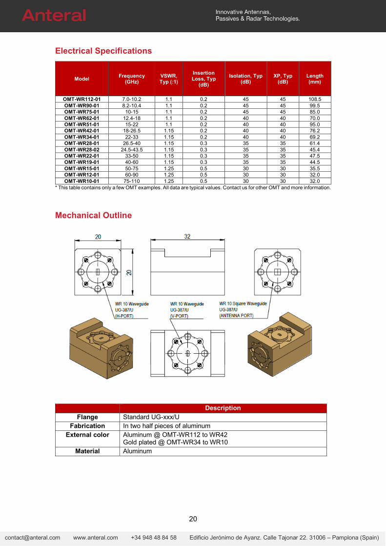
Mechanical Outline
Description Flange Standard UG-xxx/U
Fabrication In two half pieces of aluminum External color Aluminum @ OMT-WR112 to WR42
Gold plated @ OMT-WR34 to WR10 Material Aluminum
21
[email protected] www.anteral.com +34 948 48 84 58 Edificio Jerónimo de Ayanz. Calle Tajonar 22. 31006 – Pamplona (Spain)
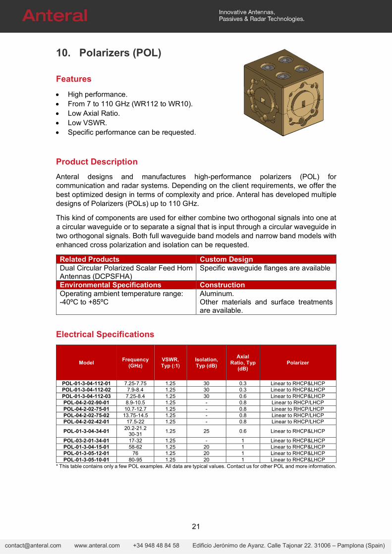
10. Polarizers (POL)
Features
High performance. From 7 to 110 GHz (WR112 to WR10). Low Axial Ratio. Low VSWR. Specific performance can be requested.
Product Description
Anteral designs and manufactures high-performance polarizers (POL) for communication and radar systems. Depending on the client requirements, we offer the best optimized design in terms of complexity and price. Anteral has developed multiple designs of Polarizers (POLs) up to 110 GHz.
This kind of components are used for either combine two orthogonal signals into one at a circular waveguide or to separate a signal that is input through a circular waveguide in two orthogonal signals. Both full waveguide band models and narrow band models with enhanced cross polarization and isolation can be requested.
Related Products Custom DesignDual Circular Polarized Scalar Feed Horn Antennas (DCPSFHA)
Specific waveguide flanges are available
Environmental Specifications ConstructionOperating ambient temperature range: -40ºC to +85ºC
Aluminum. Other materials and surface treatments are available.
Electrical Specifications
Model Frequency
(GHz) VSWR, Typ (:1)
Isolation, Typ (dB)
Axial Ratio, Typ
(dB) Polarizer
POL-01-3-04-112-01 7.25-7.75 1.25 30 0.3 Linear to RHCP&LHCP POL-01-3-04-112-02 7.9-8.4 1.25 30 0.3 Linear to RHCP&LHCP POL-01-3-04-112-03 7.25-8.4 1.25 30 0.6 Linear to RHCP&LHCP POL-04-2-02-90-01 8.9-10.5 1.25 - 0.8 Linear to RHCP/LHCP POL-04-2-02-75-01 10.7-12.7 1.25 - 0.8 Linear to RHCP/LHCP POL-04-2-02-75-02 13.75-14.5 1.25 - 0.8 Linear to RHCP/LHCP POL-04-2-02-42-01 17.5-22 1.25 - 0.8 Linear to RHCP/LHCP
POL-01-3-04-34-01 20.2-21.2
30-31 1.25 25 0.6 Linear to RHCP&LHCP
POL-03-2-01-34-01 17-32 1.25 - 1 Linear to RHCP&LHCP POL-01-3-04-15-01 58-62 1.25 20 1 Linear to RHCP&LHCP POL-01-3-05-12-01 76 1.25 20 1 Linear to RHCP&LHCP POL-01-3-05-10-01 80-95 1.25 20 1 Linear to RHCP&LHCP
* This table contains only a few POL examples. All data are typical values. Contact us for other POL and more information.
22
[email protected] www.anteral.com +34 948 48 84 58 Edificio Jerónimo de Ayanz. Calle Tajonar 22. 31006 – Pamplona (Spain)
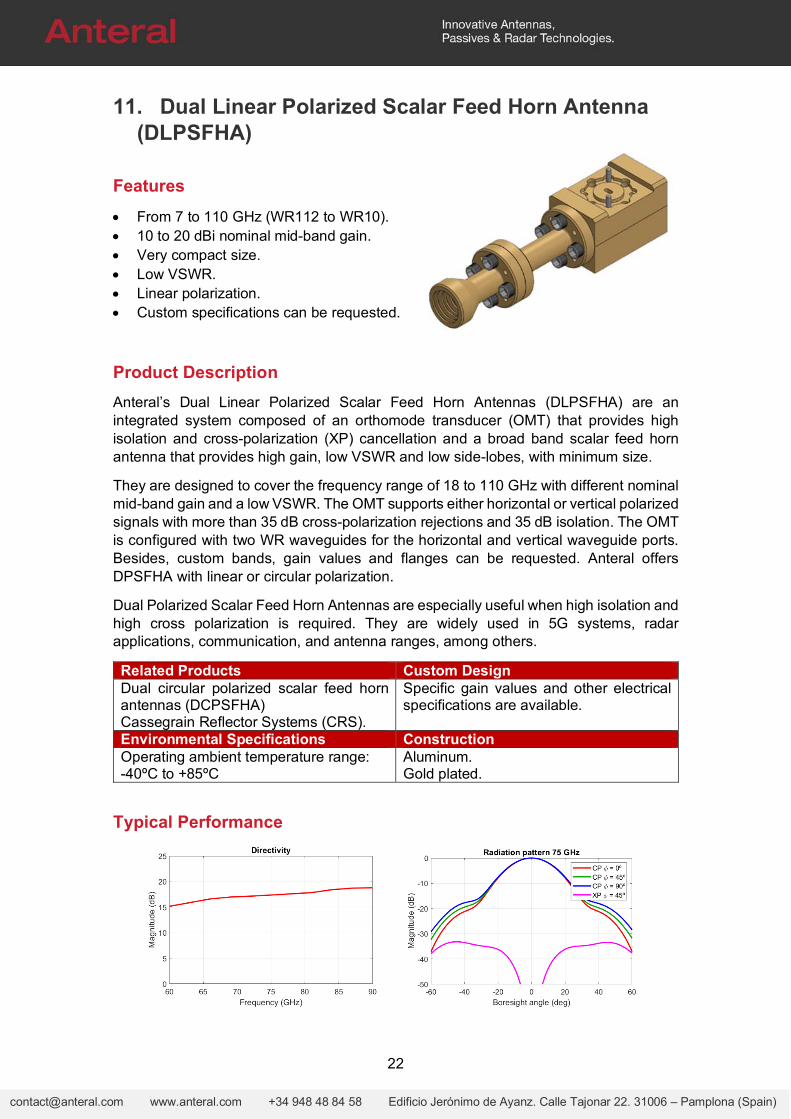
11. Dual Linear Polarized Scalar Feed Horn Antenna (DLPSFHA)
Features
From 7 to 110 GHz (WR112 to WR10). 10 to 20 dBi nominal mid-band gain. Very compact size. Low VSWR. Linear polarization. Custom specifications can be requested.
Product Description
Anteral’s Dual Linear Polarized Scalar Feed Horn Antennas (DLPSFHA) are an integrated system composed of an orthomode transducer (OMT) that provides high isolation and cross-polarization (XP) cancellation and a broad band scalar feed horn antenna that provides high gain, low VSWR and low side-lobes, with minimum size.
They are designed to cover the frequency range of 18 to 110 GHz with different nominal mid-band gain and a low VSWR. The OMT supports either horizontal or vertical polarized signals with more than 35 dB cross-polarization rejections and 35 dB isolation. The OMT is configured with two WR waveguides for the horizontal and vertical waveguide ports. Besides, custom bands, gain values and flanges can be requested. Anteral offers DPSFHA with linear or circular polarization.
Dual Polarized Scalar Feed Horn Antennas are especially useful when high isolation and high cross polarization is required. They are widely used in 5G systems, radar applications, communication, and antenna ranges, among others.
Related Products Custom DesignDual circular polarized scalar feed horn antennas (DCPSFHA) Cassegrain Reflector Systems (CRS).
Specific gain values and other electrical specifications are available.
Environmental Specifications ConstructionOperating ambient temperature range: -40ºC to +85ºC
Aluminum. Gold plated.
Typical Performance
23
[email protected] www.anteral.com +34 948 48 84 58 Edificio Jerónimo de Ayanz. Calle Tajonar 22. 31006 – Pamplona (Spain)
Electrical Specifications
Model Frequency
(GHz) VSWR
(:1) Directivity
(dBi)
3dB beamwidth
(deg) Sidelobe (dB)
Isolation (dB)
XP (dB) (±10deg)
E-plane
H-plane
E-plane
H-plane
DLPSFHA-10-WR42
18-26.5 1.15 12.3 43.6 43.6 -26.4 -26.4 35 40
DLPSFHA-18-WR42
18-26.5 1.15 19.5 21 21 -33.6 -33.6 35 40
DLPSFHA-10-WR28
26.5-40 1.15 11.7 46.4 46.4 -25.8 -25.8 35 40
DLPSFHA-15-WR28
24.5-43.5 1.15 16 31.8 31.8 -16.3 -16.3 35 30
DLPSFHA-18-WR28
26.5-40 1.15 19.4 21 21 -33.6 -33.6 35 40
DLPSFHA-15-WR22
33-50 1.15 15.1 38.2 38.2 -32.1 -32.1 35 30
DLPSFHA-17-WR19
40-60 1.15 16.9 25.8 25.8 -34 -34 35 40
DLPSFHA-13-WR19
40-60 1.15 12.7 43.2 43.2 -24.9 -24.9 35 35
DLPSFHA-17-WR15
50-75 1.25 17 26 26 -36.3 -36.3 30 40
DLPSFHA-13-WR15
50-75 1.25 12.5 45.6 45.6 -24.6 -24.6 30 35
DLPSFHA-18-WR12
60-90 1.25 17.9 22.1 22.1 -26 -26 30 40
DLPSFHA-17-WR12
60-90 1.25 17.2 26.3 26.3 -36.3 -36.3 30 40
DLPSFHA-13-WR12
60-90 1.25 12.6 43 43 -25.4 -25.4 30 35
DLPSFHA-17-WR10
75-110 1.25 16.9 26.3 26.3 -35.1 -35.1 30 40
DLPSFHA-13-WR10
75-110 1.25 13.2 39.2 39.2 -25.3 -25.3 30 35
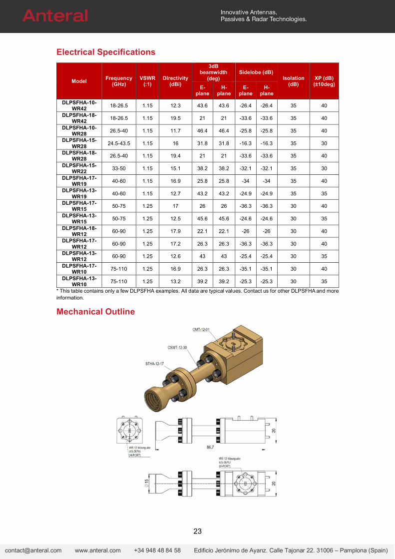
* This table contains only a few DLPSFHA examples. All data are typical values. Contact us for other DLPSFHA and more information.
Mechanical Outline
24
[email protected] www.anteral.com +34 948 48 84 58 Edificio Jerónimo de Ayanz. Calle Tajonar 22. 31006 – Pamplona (Spain)
12. Dual Circular Polarized Scalar Feed Horn Antenna (DCPSFHA)
Features
From 7 to 110 GHz (WR112 to WR10). 10 to 30 dBi nominal mid-band gain. Very compact size. Low VSWR. LHCP and RHCP polarization. Custom specifications can be requested.
Product Description
Anteral’s Dual Circular Polarized Scalar Feed Horn Antennas (DCPSFHA) are an integrated system composed of a waveguide polarizer (POL) that provides high isolation and cross-polarization (XP) cancellation and a broad band scalar feed horn antenna that provides high gain, low VSWR and low side-lobes, with minimum size.
They are designed with different nominal mid-band gain and a low VSWR. The polarizer (POL) supports either LHCP and RHCP polarized signals with high cross-polarization rejections and isolation. The polarizer is configured with two WR waveguides for the LHCP and RHCP waveguide ports. Besides, custom bands, gain values and flanges can be requested. Anteral offers DPSFHA with linear or circular polarization.
Dual Polarized Scalar Feed Horn Antennas are especially useful when high isolation and high cross polarization is required. They are widely used in 5G systems, radar applications, communication, and antenna ranges, among others.
Related Products Custom DesignDual circular polarized scalar feed horn antennas (DCPSFHA) Cassegrain Reflector Systems (CRS).
Specific gain values and other electrical specifications are available.
Environmental Specifications ConstructionOperating ambient temperature range: -40ºC to +85ºC
Aluminum. Gold plated.
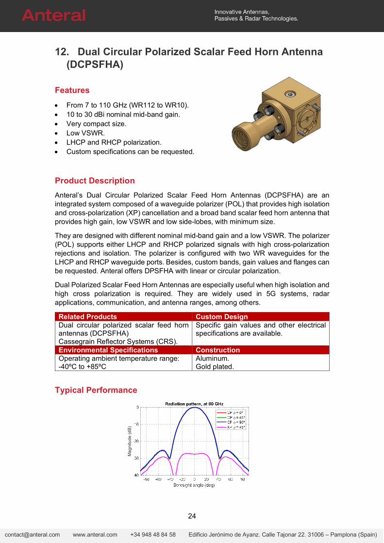
Typical Performance
Ma
gn
itud
e (
dB
)
25
[email protected] www.anteral.com +34 948 48 84 58 Edificio Jerónimo de Ayanz. Calle Tajonar 22. 31006 – Pamplona (Spain)
13. Dual Linear Polarized Lens Horn Antenna (DLPLHA)
Features
From 8.2 to 110 GHz (WR90 to WR10). 30 dBi nominal mid-band gain. Very compact size. Low VSWR. Linear polarization. Custom specifications can be requested.
Product Description
Anteral’s Dual Polarized Lens Horn Antennas (DPLHA) are an integrated system composed of an orthomode transducer (OMT) that provides high isolation and cross-polarization (XP) cancellation and a conical horn antenna with a plano-convex Teflon (PTFE) lens added in the aperture, in order to apply phase correction and achieve high gain, low VSWR and low side-lobes, with minimum size.
They are designed to cover the frequency range of 8 to 110 GHz in 12 bands with 30 dBi nominal mid-band gain and a typical VSWR of 1.25. The OMT supports either horizontal or vertical polarized signals with more than 35 dB cross-polarization rejections and 35 dB isolation. The OMT is configured with two waveguide ports for the horizontal and vertical polarization. Besides, custom bands and gain values can be requested. Anteral offers LHAs with linear or circular polarization.
Dual Polarized Lens Horn Antennas are especially useful when high gain is required with the minimum size. Therefore, these antennas are widely used in radar applications, communication links and meteorological systems, among others. New cutting-edge space applications include LHA’s for MiniSat, MicroSat, NanoSat and CubeSat communications.
Related Products Custom DesignDual Polarized High Gain Lens Horns Antennas. Cassegrain Reflector Systems.
Specific gain values and waveguide flange are available.
Environmental Specifications ConstructionOperating ambient temperature range: -40ºC to +85ºC
Aluminum.
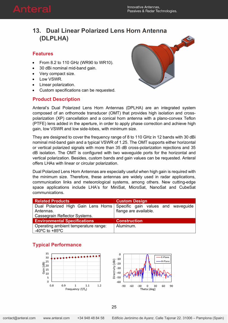
Typical Performance
26
[email protected] www.anteral.com +34 948 48 84 58 Edificio Jerónimo de Ayanz. Calle Tajonar 22. 31006 – Pamplona (Spain)
Electrical Specifications
Model Frequency
(GHz)
VSWR (:1), Typ
Directivity, Typ (dBi)
3dB beamwidth (deg), Typ
Sidelobe (dB), Typ Isolation
(dB), Typ
XP (dB), Typ E-
plane H-
plane E-
plane H-
plane
DLPLHA-30-WR90
8.2-10.4 1.25 30.4 4.5 6.4 -18 -28 35 35
DLPLHA-30-WR75
10-15 1.25 30.8 4.3 5.9 -15.9 -30.9 35 35
DLPLHA-20-WR62
12.4-18 1.25 31.1 4.1 5.9 -17 -28 35 35
DLPLHA-30-WR51
15-22 1.25 31.9 3.7 5.5 -19.7 -23.4 35 35
DLPLHA-30-WR42
18-26.5 1.25 31 4.2 5.6 -17 -29 35 35
DLPLHA-30-WR34
22-33 1.25 30.4 4.6 6 -13.7 -24.9 35 35
DLPLHA-30-WR28
26.5-40 1.25 30.8 4.5 5.7 -16 -28 35 35
DLPLHA-30-WR22
33-50 1.25 30.5 4.8 5.9 -15 -26 35 35
DLPLHA-30-WR19
40-60 1.25 30.5 4.6 5.9 -14 -28 35 35
DLPLHA-30-WR15
50-75 1.25 30.3 4.9 6.3 -14 -28 35 35
DLPLHA-30-WR12
60-90 1.25 30.2 4.8 6.1 -13 -28 35 35
DLPLHA-30-WR10
75-110 1.25 30.1 5.1 5.1 -13 -26 35 35
Mechanical Outline
27
[email protected] www.anteral.com +34 948 48 84 58 Edificio Jerónimo de Ayanz. Calle Tajonar 22. 31006 – Pamplona (Spain)
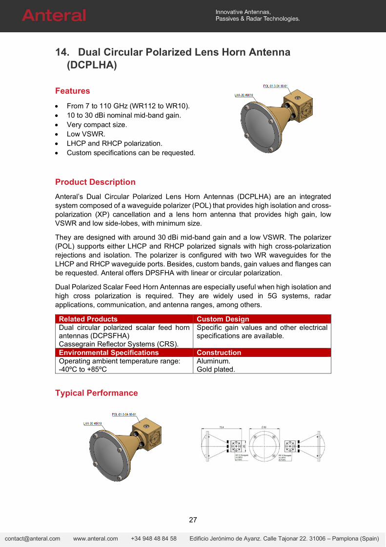
14. Dual Circular Polarized Lens Horn Antenna (DCPLHA)
Features
From 7 to 110 GHz (WR112 to WR10). 10 to 30 dBi nominal mid-band gain. Very compact size. Low VSWR. LHCP and RHCP polarization. Custom specifications can be requested.
Product Description
Anteral’s Dual Circular Polarized Lens Horn Antennas (DCPLHA) are an integrated system composed of a waveguide polarizer (POL) that provides high isolation and cross-polarization (XP) cancellation and a lens horn antenna that provides high gain, low VSWR and low side-lobes, with minimum size.
They are designed with around 30 dBi mid-band gain and a low VSWR. The polarizer (POL) supports either LHCP and RHCP polarized signals with high cross-polarization rejections and isolation. The polarizer is configured with two WR waveguides for the LHCP and RHCP waveguide ports. Besides, custom bands, gain values and flanges can be requested. Anteral offers DPSFHA with linear or circular polarization.
Dual Polarized Scalar Feed Horn Antennas are especially useful when high isolation and high cross polarization is required. They are widely used in 5G systems, radar applications, communication, and antenna ranges, among others.
Related Products Custom DesignDual circular polarized scalar feed horn antennas (DCPSFHA) Cassegrain Reflector Systems (CRS).
Specific gain values and other electrical specifications are available.
Environmental Specifications ConstructionOperating ambient temperature range: -40ºC to +85ºC
Aluminum. Gold plated.
Typical Performance
28
[email protected] www.anteral.com +34 948 48 84 58 Edificio Jerónimo de Ayanz. Calle Tajonar 22. 31006 – Pamplona (Spain)
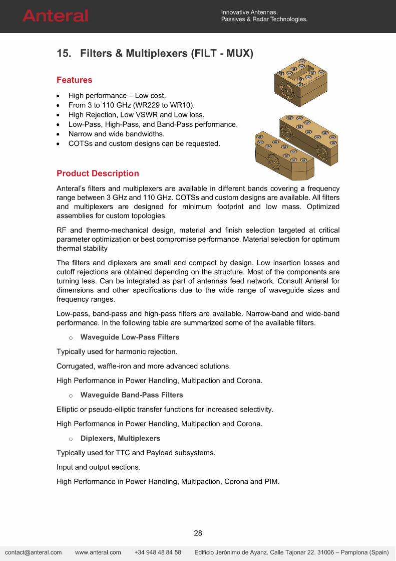
15. Filters & Multiplexers (FILT - MUX)
Features
High performance – Low cost. From 3 to 110 GHz (WR229 to WR10). High Rejection, Low VSWR and Low loss. Low-Pass, High-Pass, and Band-Pass performance. Narrow and wide bandwidths. COTSs and custom designs can be requested.
Product Description
Anteral’s filters and multiplexers are available in different bands covering a frequency range between 3 GHz and 110 GHz. COTSs and custom designs are available. All filters and multiplexers are designed for minimum footprint and low mass. Optimized assemblies for custom topologies.
RF and thermo-mechanical design, material and finish selection targeted at critical parameter optimization or best compromise performance. Material selection for optimum thermal stability
The filters and diplexers are small and compact by design. Low insertion losses and cutoff rejections are obtained depending on the structure. Most of the components are turning less. Can be integrated as part of antennas feed network. Consult Anteral for dimensions and other specifications due to the wide range of waveguide sizes and frequency ranges.
Low-pass, band-pass and high-pass filters are available. Narrow-band and wide-band performance. In the following table are summarized some of the available filters.
o Waveguide Low-Pass Filters
Typically used for harmonic rejection.
Corrugated, waffle-iron and more advanced solutions.
High Performance in Power Handling, Multipaction and Corona.
o Waveguide Band-Pass Filters
Elliptic or pseudo-elliptic transfer functions for increased selectivity.
High Performance in Power Handling, Multipaction and Corona.
o Diplexers, Multiplexers
Typically used for TTC and Payload subsystems.
Input and output sections.
High Performance in Power Handling, Multipaction, Corona and PIM.
29
[email protected] www.anteral.com +34 948 48 84 58 Edificio Jerónimo de Ayanz. Calle Tajonar 22. 31006 – Pamplona (Spain)
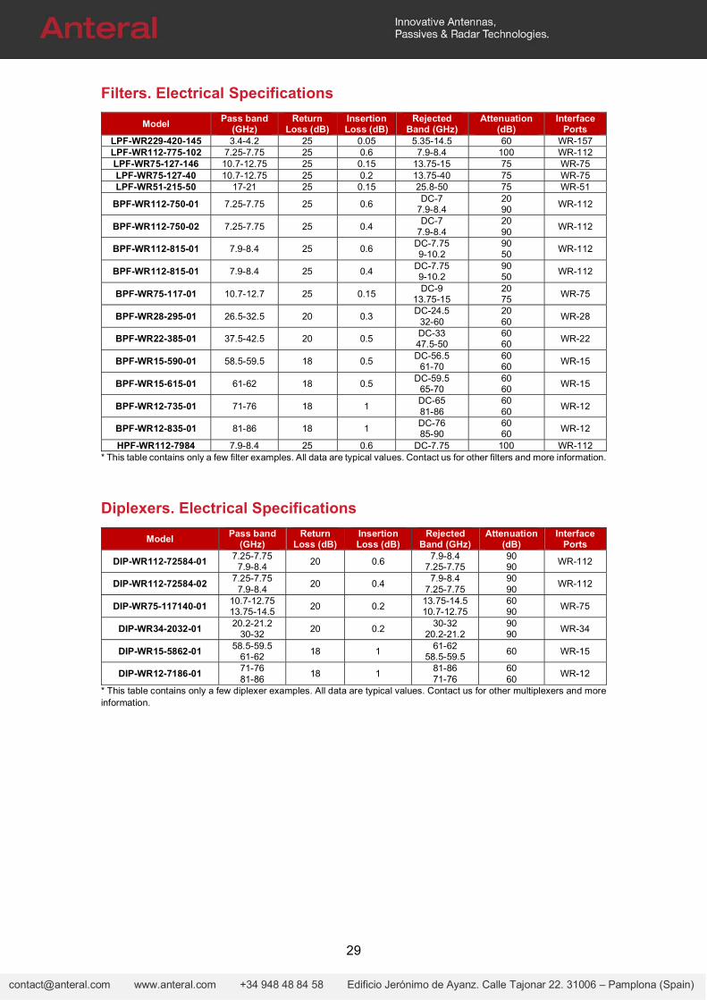
Filters. Electrical Specifications
Model Pass band
(GHz) Return
Loss (dB) Insertion Loss (dB)
Rejected Band (GHz)
Attenuation (dB)
Interface Ports
LPF-WR229-420-145 3.4-4.2 25 0.05 5.35-14.5 60 WR-157 LPF-WR112-775-102 7.25-7.75 25 0.6 7.9-8.4 100 WR-112 LPF-WR75-127-146 10.7-12.75 25 0.15 13.75-15 75 WR-75 LPF-WR75-127-40 10.7-12.75 25 0.2 13.75-40 75 WR-75 LPF-WR51-215-50 17-21 25 0.15 25.8-50 75 WR-51
BPF-WR112-750-01 7.25-7.75 25 0.6 DC-7
7.9-8.4 20 90
WR-112
BPF-WR112-750-02 7.25-7.75 25 0.4 DC-7
7.9-8.4 20 90
WR-112
BPF-WR112-815-01 7.9-8.4 25 0.6 DC-7.75 9-10.2
90 50
WR-112
BPF-WR112-815-01 7.9-8.4 25 0.4 DC-7.75 9-10.2
90 50
WR-112
BPF-WR75-117-01 10.7-12.7 25 0.15 DC-9
13.75-15 20 75
WR-75
BPF-WR28-295-01 26.5-32.5 20 0.3 DC-24.5
32-60 20 60
WR-28
BPF-WR22-385-01 37.5-42.5 20 0.5 DC-33 47.5-50
60 60
WR-22
BPF-WR15-590-01 58.5-59.5 18 0.5 DC-56.5
61-70 60 60
WR-15
BPF-WR15-615-01 61-62 18 0.5 DC-59.5
65-70 60 60
WR-15
BPF-WR12-735-01 71-76 18 1 DC-65 81-86
60 60
WR-12
BPF-WR12-835-01 81-86 18 1 DC-76 85-90
60 60
WR-12
HPF-WR112-7984 7.9-8.4 25 0.6 DC-7.75 100 WR-112 * This table contains only a few filter examples. All data are typical values. Contact us for other filters and more information.
Diplexers. Electrical Specifications
Model Pass band
(GHz) Return
Loss (dB) Insertion Loss (dB)
Rejected Band (GHz)
Attenuation (dB)
Interface Ports
DIP-WR112-72584-01 7.25-7.75
7.9-8.4 20 0.6
7.9-8.4 7.25-7.75
90 90
WR-112
DIP-WR112-72584-02 7.25-7.75
7.9-8.4 20 0.4
7.9-8.4 7.25-7.75
90 90
WR-112
DIP-WR75-117140-01 10.7-12.75 13.75-14.5
20 0.2 13.75-14.5 10.7-12.75
60 90
WR-75
DIP-WR34-2032-01 20.2-21.2
30-32 20 0.2
30-32 20.2-21.2
90 90
WR-34
DIP-WR15-5862-01 58.5-59.5
61-62 18 1
61-62 58.5-59.5
60 WR-15
DIP-WR12-7186-01 71-76 81-86
18 1 81-86 71-76
60 60
WR-12
* This table contains only a few diplexer examples. All data are typical values. Contact us for other multiplexers and more information.
30
[email protected] www.anteral.com +34 948 48 84 58 Edificio Jerónimo de Ayanz. Calle Tajonar 22. 31006 – Pamplona (Spain)
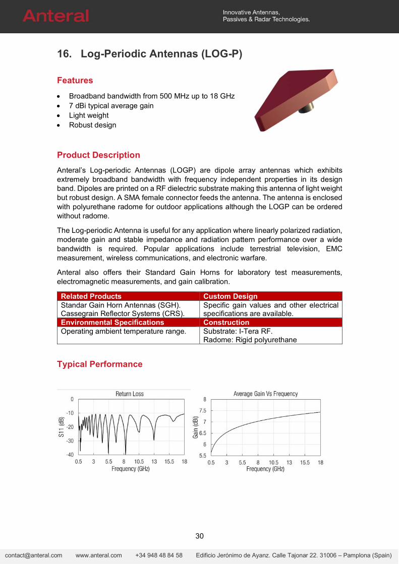
16. Log-Periodic Antennas (LOG-P)
Features
Broadband bandwidth from 500 MHz up to 18 GHz 7 dBi typical average gain Light weight Robust design
Product Description
Anteral’s Log-periodic Antennas (LOGP) are dipole array antennas which exhibits extremely broadband bandwidth with frequency independent properties in its design band. Dipoles are printed on a RF dielectric substrate making this antenna of light weight but robust design. A SMA female connector feeds the antenna. The antenna is enclosed with polyurethane radome for outdoor applications although the LOGP can be ordered without radome.
The Log-periodic Antenna is useful for any application where linearly polarized radiation, moderate gain and stable impedance and radiation pattern performance over a wide bandwidth is required. Popular applications include terrestrial television, EMC measurement, wireless communications, and electronic warfare.
Anteral also offers their Standard Gain Horns for laboratory test measurements, electromagnetic measurements, and gain calibration.
Related Products Custom DesignStandar Gain Horn Antennas (SGH). Cassegrain Reflector Systems (CRS).
Specific gain values and other electrical specifications are available.
Environmental Specifications ConstructionOperating ambient temperature range. Substrate: I-Tera RF.
Radome: Rigid polyurethane
Typical Performance

31
[email protected] www.anteral.com +34 948 48 84 58 Edificio Jerónimo de Ayanz. Calle Tajonar 22. 31006 – Pamplona (Spain)
Specifications
Model Pass band (GHz)
Return Loss, Typ (dB)
Directivity, Typ (dBi)
3 dB Beamwaist,
E-plane, Typ (deg)
3 dB Beamwaist,
H-plane, Typ (deg)
Interface Ports
Radome
LOGP-SMA-0518 0.5-18 -15 7 70 110 SMA (F) NO LOGP-SMA-0518-R 0.5-18 -15 7 70 110 SMA (F) YES
LOGP-SMA-218 2-18 -15 7 70 110 SMA (F) NO LOGP-SMA-218-R 2-18 -15 7 70 110 SMA (F) YES
Mechanical Outline
LOGP-SMA-0518-R
LOGP-SMA-218-R
32
[email protected] www.anteral.com +34 948 48 84 58 Edificio Jerónimo de Ayanz. Calle Tajonar 22. 31006 – Pamplona (Spain)
17. Wire Grid Polarizers (WGP)
Features
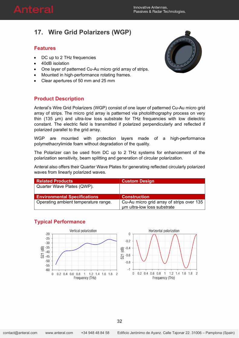
DC up to 2 THz frequencies 40dB isolation One layer of patterned Cu-Au micro grid array of strips. Mounted in high-performance rotating frames. Clear apertures of 50 mm and 25 mm
Product Description
Anteral’s Wire Grid Polarizers (WGP) consist of one layer of patterned Cu-Au micro grid array of strips. The micro grid array is patterned via photolithography process on very thin (135 µm) and ultra-low loss substrate for THz frequencies with low dielectric constant. The electric field is transmitted if polarized perpendicularly and reflected if polarized parallel to the grid array.
WGP are mounted with protection layers made of a high-performance polymethacrylimide foam without degradation of the quality.
The Polarizer can be used from DC up to 2 THz systems for enhancement of the polarization sensitivity, beam splitting and generation of circular polarization.
Anteral also offers their Quarter Wave Plates for generating reflected circularly polarized waves from linearly polarized waves.
Related Products Custom DesignQuarter Wave Plates (QWP).
Environmental Specifications ConstructionOperating ambient temperature range. Cu-Au micro grid array of strips over 135
µm ultra-low loss substrate
Typical Performance
33
[email protected] www.anteral.com +34 948 48 84 58 Edificio Jerónimo de Ayanz. Calle Tajonar 22. 31006 – Pamplona (Spain)
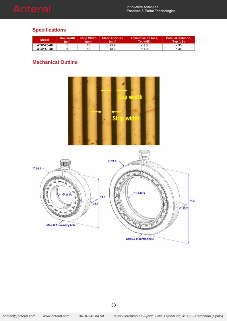
Specifications
Model Gap Width
(µm) Strip Width
(µm) Clear Aperture
(mm) Transmission loss,
Typ (dB) Parallel Isolation,
Typ (dB) WGP-25-40 5 10 23.9 < 1.0 > 35 WGP-50-40 5 10 48.3 < 1.0 > 38
Mechanical Outline
34
[email protected] www.anteral.com +34 948 48 84 58 Edificio Jerónimo de Ayanz. Calle Tajonar 22. 31006 – Pamplona (Spain)
18. Quarter Wave Plates (QWP)
Features
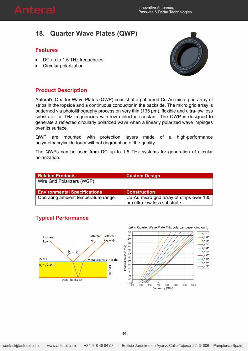
DC up to 1.5 THz frequencies Circular polarization
Product Description
Anteral’s Quarter Wave Plates (QWP) consist of a patterned Cu-Au micro grid array of strips in the topside and a continuous conductor in the backside. The micro grid array is patterned via photolithography process on very thin (135 μm), flexible and ultra-low loss substrate for THz frequencies with low dielectric constant. The QWP is designed to generate a reflected circularly polarized wave when a linearly polarized wave impinges over its surface.
QWP are mounted with protection layers made of a high-performance polymethacrylimide foam without degradation of the quality.
The QWPs can be used from DC up to 1.5 THz systems for generation of circular polarization.
Related Products Custom DesignWire Grid Polarizers (WGP).
Environmental Specifications ConstructionOperating ambient temperature range. Cu-Au micro grid array of strips over 135
µm ultra-low loss substrate
Typical Performance
35
[email protected] www.anteral.com +34 948 48 84 58 Edificio Jerónimo de Ayanz. Calle Tajonar 22. 31006 – Pamplona (Spain)
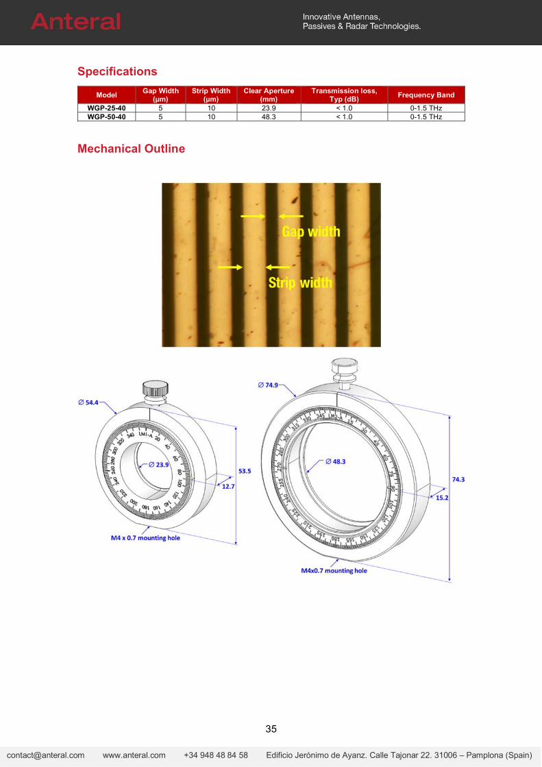
Specifications
Model Gap Width
(µm) Strip Width
(µm) Clear Aperture
(mm) Transmission loss,
Typ (dB) Frequency Band
WGP-25-40 5 10 23.9 < 1.0 0-1.5 THz WGP-50-40 5 10 48.3 < 1.0 0-1.5 THz
Mechanical Outline
36
[email protected] www.anteral.com +34 948 48 84 58 Edificio Jerónimo de Ayanz. Calle Tajonar 22. 31006 – Pamplona (Spain)
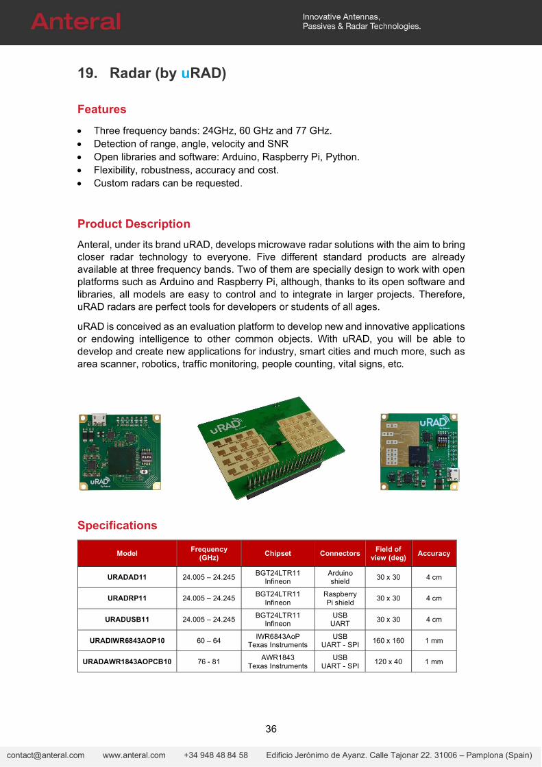
19. Radar (by uRAD)
Features
Three frequency bands: 24GHz, 60 GHz and 77 GHz. Detection of range, angle, velocity and SNR Open libraries and software: Arduino, Raspberry Pi, Python. Flexibility, robustness, accuracy and cost. Custom radars can be requested.
Product Description
Anteral, under its brand uRAD, develops microwave radar solutions with the aim to bring closer radar technology to everyone. Five different standard products are already available at three frequency bands. Two of them are specially design to work with open platforms such as Arduino and Raspberry Pi, although, thanks to its open software and libraries, all models are easy to control and to integrate in larger projects. Therefore, uRAD radars are perfect tools for developers or students of all ages.
uRAD is conceived as an evaluation platform to develop new and innovative applications or endowing intelligence to other common objects. With uRAD, you will be able to develop and create new applications for industry, smart cities and much more, such as area scanner, robotics, traffic monitoring, people counting, vital signs, etc.
Specifications
Model Frequency
(GHz) Chipset Connectors
Field of view (deg)
Accuracy
URADAD11 24.005 – 24.245 BGT24LTR11
Infineon Arduino shield
30 x 30 4 cm
URADRP11 24.005 – 24.245 BGT24LTR11
Infineon Raspberry Pi shield
30 x 30 4 cm
URADUSB11 24.005 – 24.245 BGT24LTR11
Infineon USB
UART 30 x 30 4 cm
URADIWR6843AOP10 60 – 64 IWR6843AoP
Texas Instruments USB
UART - SPI 160 x 160 1 mm
URADAWR1843AOPCB10 76 - 81 AWR1843
Texas Instruments USB
UART - SPI 120 x 40 1 mm


![WATT MAS - Modulares Antriebssystem - …percentage p3 from table V1 and V2. Vedrehspiel / backlash s Übersetzung / ratio i [·] Diagramm V1 / diagram V1 Tabelle V1 / table V1 Beispiel](https://img.dokumen.tips/doc/110x75/5ec42f0037c99e4ad7465a5b/watt-mas-modulares-antriebssystem-percentage-p3-from-table-v1-and-v2-vedrehspiel.jpg)