Embed Size (px)
Citation preview

ANTENNA SOLUTIONS
TRI-SECTOR Base Station Antennas & Enclosures
TRIO™ and UNICELL™
w w w . a m p h e n o l - a n t e n n a s . c o mw w w . a m p h e n o l - a n t e n n a s . c o m
ANTENNA SOLUTIONS
w w w . a m p h e n o l - a n t e n n a s . c o m

Table of ContentsThe landscape is getting “crowded”
A “win-win” solution
TRIO Antennas TRIO Antennas Matrix. . . . . . . . . . . . . . . . . . . . . . . . . . . . . . . . . . . . . . . . . . . . . . . . 9
WB3X080X06F250. . . . . . . . . . . . . . . . . . . . . . . . . . . . . . . . . . . . . . . . . . . . . . . . . .10
WB3X080X12Fx50. . . . . . . . . . . . . . . . . . . . . . . . . . . . . . . . . . . . . . . . . . . . . . . . . .11
GSM3X75-13-A. . . . . . . . . . . . . . . . . . . . . . . . . . . . . . . . . . . . . . . . . . . . . . . . . . . . .13
GSM3X75-22-A. . . . . . . . . . . . . . . . . . . . . . . . . . . . . . . . . . . . . . . . . . . . . . . . . . . . .15
5176703. . . . . . . . . . . . . . . . . . . . . . . . . . . . . . . . . . . . . . . . . . . . . . . . . . . . . . . . . .17
5162703. . . . . . . . . . . . . . . . . . . . . . . . . . . . . . . . . . . . . . . . . . . . . . . . . . . . . . . . . . 21
5230703. . . . . . . . . . . . . . . . . . . . . . . . . . . . . . . . . . . . . . . . . . . . . . . . . . . . . . . . . . 25
WB3X072X18x00. . . . . . . . . . . . . . . . . . . . . . . . . . . . . . . . . . . . . . . . . . . . . . . . . . . 29
WB3X072X24x00. . . . . . . . . . . . . . . . . . . . . . . . . . . . . . . . . . . . . . . . . . . . . . . . . . . 33
5066222. . . . . . . . . . . . . . . . . . . . . . . . . . . . . . . . . . . . . . . . . . . . . . . . . . . . . . . . . . 35
5067222. . . . . . . . . . . . . . . . . . . . . . . . . . . . . . . . . . . . . . . . . . . . . . . . . . . . . . . . . . 37
5176903. . . . . . . . . . . . . . . . . . . . . . . . . . . . . . . . . . . . . . . . . . . . . . . . . . . . . . . . . . 39
5162903. . . . . . . . . . . . . . . . . . . . . . . . . . . . . . . . . . . . . . . . . . . . . . . . . . . . . . . . . . 43
5230903. . . . . . . . . . . . . . . . . . . . . . . . . . . . . . . . . . . . . . . . . . . . . . . . . . . . . . . . . . 47
5863703. . . . . . . . . . . . . . . . . . . . . . . . . . . . . . . . . . . . . . . . . . . . . . . . . . . . . . . . . . 51
5880713. . . . . . . . . . . . . . . . . . . . . . . . . . . . . . . . . . . . . . . . . . . . . . . . . . . . . . . . . . 55
5270500. . . . . . . . . . . . . . . . . . . . . . . . . . . . . . . . . . . . . . . . . . . . . . . . . . . . . . . . . . 59
5270200. . . . . . . . . . . . . . . . . . . . . . . . . . . . . . . . . . . . . . . . . . . . . . . . . . . . . . . . . . 61
5270400. . . . . . . . . . . . . . . . . . . . . . . . . . . . . . . . . . . . . . . . . . . . . . . . . . . . . . . . . . 63
5177703. . . . . . . . . . . . . . . . . . . . . . . . . . . . . . . . . . . . . . . . . . . . . . . . . . . . . . . . . . 65
5863903. . . . . . . . . . . . . . . . . . . . . . . . . . . . . . . . . . . . . . . . . . . . . . . . . . . . . . . . . . 67
5860903. . . . . . . . . . . . . . . . . . . . . . . . . . . . . . . . . . . . . . . . . . . . . . . . . . . . . . . . . . 71
5880903. . . . . . . . . . . . . . . . . . . . . . . . . . . . . . . . . . . . . . . . . . . . . . . . . . . . . . . . . . 75
SL3X065X17x00. . . . . . . . . . . . . . . . . . . . . . . . . . . . . . . . . . . . . . . . . . . . . . . . . . . .79
WB3X065T17x00 . . . . . . . . . . . . . . . . . . . . . . . . . . . . . . . . . . . . . . . . . . . . . . . . . . . 81
DS3X065X17x10. . . . . . . . . . . . . . . . . . . . . . . . . . . . . . . . . . . . . . . . . . . . . . . . . . . 83
DS3X065X17x00. . . . . . . . . . . . . . . . . . . . . . . . . . . . . . . . . . . . . . . . . . . . . . . . . . . 85
TW3X065X17x00. . . . . . . . . . . . . . . . . . . . . . . . . . . . . . . . . . . . . . . . . . . . . . . . . . . 87
TRIO Accessories. . . . . . . . . . . . . . . . . . . . . . . . . . . . . . . . . . . . . . . . . . . . . . . . . . . 90
TRIO Antenna Supports. . . . . . . . . . . . . . . . . . . . . . . . . . . . . . . . . . . . . . . . . . . . . . 92
UNICELL Enclosures and Accessories UNICELL and Antennas Compatibility. . . . . . . . . . . . . . . . . . . . . . . . . . . . . . . . . . . 98
UNX14-xx. . . . . . . . . . . . . . . . . . . . . . . . . . . . . . . . . . . . . . . . . . . . . . . . . . . . . . . . . 99
UNX20-xx. . . . . . . . . . . . . . . . . . . . . . . . . . . . . . . . . . . . . . . . . . . . . . . . . . . . . . . .100
Contact Us
5
6
8
96
101
w w w . a m p h e n o l - a n t e n n a s . c o m

ANTENNA SOLUTIONS
4

THE WIRELESS LANDSCAPE
IS GETTING “CROWDED” For more than 20 years, service providers around the world have
been deploying and expanding their networks to keep up with demand for
high quality voice and data services. Remote and industrial locations have
been the fi rst choice for cell sites but these locations are getting hard to fi nd.
The sites that do exist are now overfl owing with antennas, amplifi ers and
cabling. New cell sites are needed to deliver 3G and 4G services, but nobody
wants to see the unsightly infrastructure near their homes, schools or offi ces.
City planners and service providers need a win-win solution to insure the
availability of wireless services without degrading the visual appearance of
the community.
w w w . a m p h e n o l - a n t e n n a s . c o m
5
ANTENNA SOLUTIONS
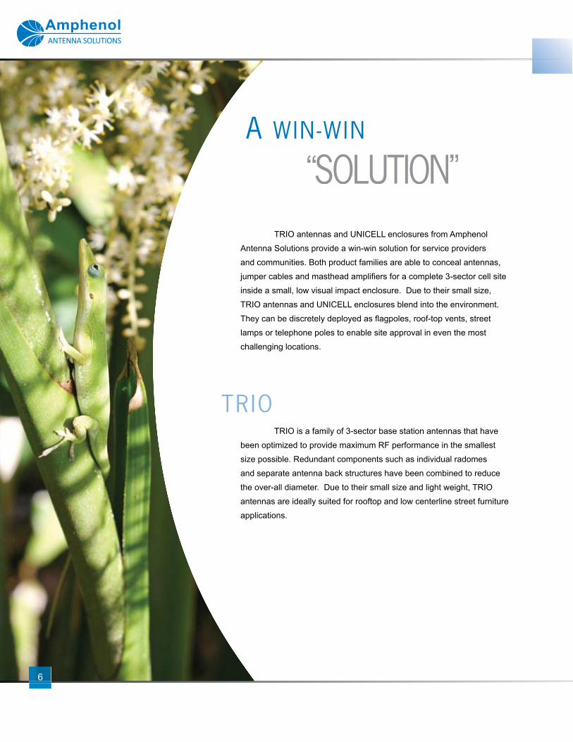
TRIO antennas and UNICELL enclosures from Amphenol
Antenna Solutions provide a win-win solution for service providers
and communities. Both product families are able to conceal antennas,
jumper cables and masthead amplifi ers for a complete 3-sector cell site
inside a small, low visual impact enclosure. Due to their small size,
TRIO antennas and UNICELL enclosures blend into the environment.
They can be discretely deployed as fl agpoles, roof-top vents, street
lamps or telephone poles to enable site approval in even the most
challenging locations.
TRIO is a family of 3-sector base station antennas that have
been optimized to provide maximum RF performance in the smallest
size possible. Redundant components such as individual radomes
and separate antenna back structures have been combined to reduce
the over-all diameter. Due to their small size and light weight, TRIO
antennas are ideally suited for rooftop and low centerline street furniture
applications.
A WIN-WIN
“SOLUTION“SOLUTION“ ”
TRIO
6

w w w . a m p h e n o l - a n t e n n a s . c o m
7
UNICELL is a family of antenna enclosures designed to accept
“off-the-shelf” base station antennas. UNICELL provides long term fl exibility
by allowing antennas on each sector to be individually replaced as coverage
requirements or available spectrum change. Light weight concealment
panels on each sector allow easy fi eld access to the internal antennas
without having to lift or remove the UNICELL structure. Enclosures can
be stacked two-high for multiband applications or to provide collocation
opportunities for a second service provider.
Amphenol Antenna Solutions has over a decade of experience
deploying TRIO and UNICELL site solutions. We understand the unique
packaging challenges associated with these sites and have designed
these products to provide trouble free installation and easy serviceability.
In addition, we have developed a full line of accessories including TMA
mounting canisters, lightning protection kits and fl ag pole adapter kits that
are simple to deploy and allow customization to meet your site requirements.
UNICELL
EXPERIENCE
ANTENNA SOLUTIONS
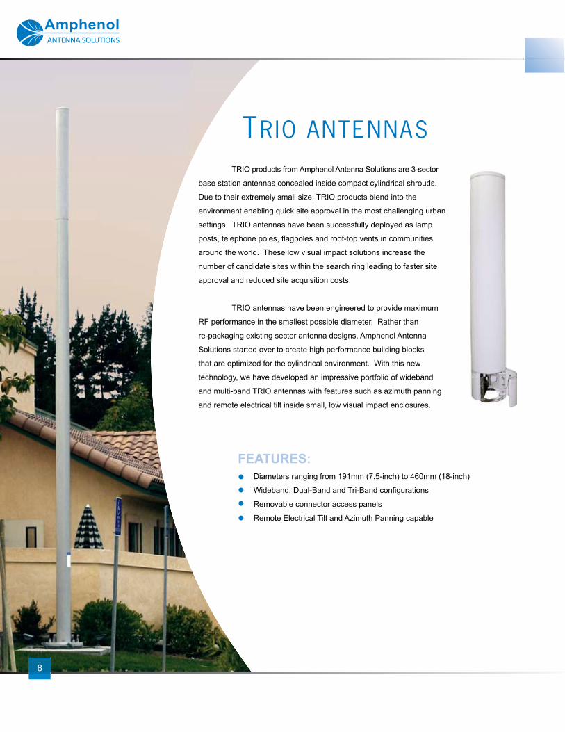
TRIO products from Amphenol Antenna Solutions are 3-sector
base station antennas concealed inside compact cylindrical shrouds.
Due to their extremely small size, TRIO products blend into the
environment enabling quick site approval in the most challenging urban
settings. TRIO antennas have been successfully deployed as lamp
posts, telephone poles, fl agpoles and roof-top vents in communities
around the world. These low visual impact solutions increase the
number of candidate sites within the search ring leading to faster site
approval and reduced site acquisition costs.
TRIO antennas have been engineered to provide maximum
RF performance in the smallest possible diameter. Rather than
re-packaging existing sector antenna designs, Amphenol Antenna
Solutions started over to create high performance building blocks
that are optimized for the cylindrical environment. With this new
technology, we have developed an impressive portfolio of wideband
and multi-band TRIO antennas with features such as azimuth panning
and remote electrical tilt inside small, low visual impact enclosures.
TRIO ANTENNAS
FEATURES:Diameters ranging from 191mm (7.5-inch) to 460mm (18-inch)
Wideband, Dual-Band and Tri-Band confi gurations
Removable connector access panels
Remote Electrical Tilt and Azimuth Panning capable
8
w w w . a m p h e n o l - a n t e n n a s . c o m
Current product offering as of time of printing. 9
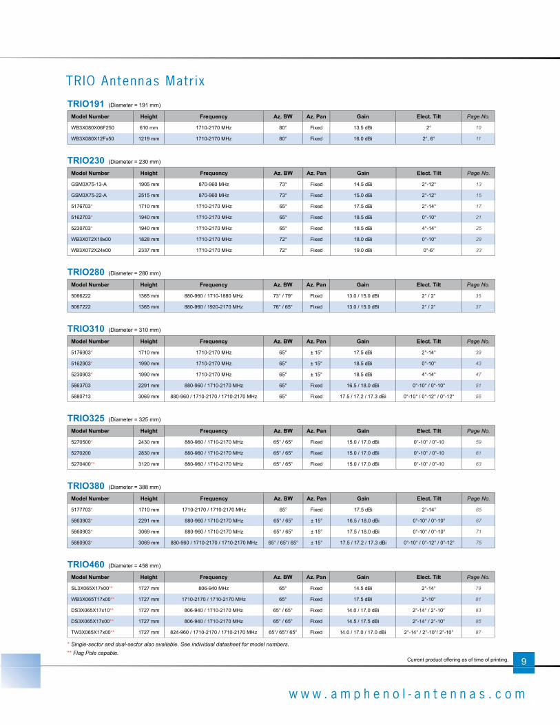
TRIO191 (Diameter = 191 mm)
Model Number Height Frequency Az. BW Az. Pan Gain Elect. Tilt Page No.
WB3X080X06F250 610 mm 1710-2170 MHz 80° Fixed 13.5 dBi 2° 10
WB3X080X12Fx50 1219 mm 1710-2170 MHz 80° Fixed 16.0 dBi 2°, 6° 11
TRIO230 (Diameter = 230 mm)
Model Number Height Frequency Az. BW Az. Pan Gain Elect. Tilt Page No.
GSM3X75-13-A 1905 mm 870-960 MHz 73° Fixed 14.5 dBi 2°-12° 13
GSM3X75-22-A 2515 mm 870-960 MHz 73° Fixed 15.0 dBi 2°-12° 15
5176703* 1710 mm 1710-2170 MHz 65° Fixed 17.5 dBi 2°-14° 17
5162703* 1940 mm 1710-2170 MHz 65° Fixed 18.5 dBi 0°-10° 21
5230703* 1940 mm 1710-2170 MHz 65° Fixed 18.5 dBi 4°-14° 25
WB3X072X18x00 1828 mm 1710-2170 MHz 72° Fixed 18.0 dBi 0°-10° 29
WB3X072X24x00 2337 mm 1710-2170 MHz 72° Fixed 19.0 dBi 0°-6° 33
TRIO280 (Diameter = 280 mm)
Model Number Height Frequency Az. BW Az. Pan Gain Elect. Tilt Page No.
5066222 1365 mm 880-960 / 1710-1880 MHz 73° / 79° Fixed 13.0 / 15.0 dBi 2° / 2° 35
5067222 1365 mm 880-960 / 1920-2170 MHz 76° / 65° Fixed 13.0 / 15.0 dBi 2° / 2° 37
TRIO310 (Diameter = 310 mm)
Model Number Height Frequency Az. BW Az. Pan Gain Elect. Tilt Page No.
5176903* 1710 mm 1710-2170 MHz 65° ± 15° 17.5 dBi 2°-14° 39
5162903* 1990 mm 1710-2170 MHz 65° ± 15° 18.5 dBi 0°-10° 43
5230903* 1990 mm 1710-2170 MHz 65° ± 15° 18.5 dBi 4°-14° 47
5863703 2291 mm 880-960 / 1710-2170 MHz 65° Fixed 16.5 / 18.0 dBi 0°-10° / 0°-10° 51
5880713 3069 mm 880-960 / 1710-2170 / 1710-2170 MHz 65° Fixed 17.5 / 17.2 / 17.3 dBi 0°-10° / 0°-12° / 0°-12° 55
TRIO325 (Diameter = 325 mm)
Model Number Height Frequency Az. BW Az. Pan Gain Elect. Tilt Page No.
5270500* 2430 mm 880-960 / 1710-2170 MHz 65° / 65° Fixed 15.0 / 17.0 dBi 0°-10° / 0°-10 59
5270200 2830 mm 880-960 / 1710-2170 MHz 65° / 65° Fixed 15.0 / 17.0 dBi 0°-10° / 0°-10 61
5270400** 3120 mm 880-960 / 1710-2170 MHz 65° / 65° Fixed 15.0 / 17.0 dBi 0°-10° / 0°-10 63
TRIO380 (Diameter = 388 mm)
Model Number Height Frequency Az. BW Az. Pan Gain Elect. Tilt Page No.
5177703* 1710 mm 1710-2170 / 1710-2170 MHz 65° Fixed 17.5 dBi 2°-14° 65
5863903* 2291 mm 880-960 / 1710-2170 MHz 65° / 65° ± 15° 16.5 / 18.0 dBi 0°-10° / 0°-10° 67
5860903* 3069 mm 880-960 / 1710-2170 MHz 65° / 65° ± 15° 17.5 / 18.0 dBi 0°-10° / 0°-10° 71
5880903* 3069 mm 880-960 / 1710-2170 / 1710-2170 MHz 65° / 65°/ 65° ± 15° 17.5 / 17.2 / 17.3 dBi 0°-10° / 0°-12° / 0°-12° 75
TRIO460 (Diameter = 458 mm)
Model Number Height Frequency Az. BW Az. Pan Gain Elect. Tilt Page No.
SL3X065X17x00** 1727 mm 806-940 MHz 65° Fixed 14.5 dBi 2°-14° 79
WB3X065T17x00** 1727 mm 1710-2170 / 1710-2170 MHz 65° Fixed 17.5 dBi 2°-10° 81
DS3X065X17x10** 1727 mm 806-940 / 1710-2170 MHz 65° / 65° Fixed 14.0 / 17.0 dBi 2°-14° / 2°-10° 83
DS3X065X17x00** 1727 mm 806-940 / 1710-2170 MHz 65° / 65° Fixed 14.5 / 17.5 dBi 2°-14° / 2°-10° 85
TW3X065X17x00** 1727 mm 824-960 / 1710-2170 / 1710-2170 MHz 65°/ 65°/ 65° Fixed 14.0 / 17.0 / 17.0 dBi 2°-14° / 2°-10°/ 2°-10° 87
* Single-sector and dual-sector also available. See individual datasheet for model numbers.
TRIO Antennas Matr ix
** Flag Pole capable.

ANTENNA SOLUTIONS
Quoted performance parameters are provided to offer typical or range values only and may vary as a result of normal manufacturing and operational conditions. Extreme operational conditions and/or stress on structural supports is beyond our control. Such conditions may result in damage to this product. Improvements to product may be made without notice.
www.amphenol-antennas.com REV0510
10
Electrical Characteristics 1710-2170 MHz
Frequency band 1710-1880 MHz 1850-1990 MHz 1900-2170 MHz
Polarization ±45°
Horizontal beamwidth 74° 78° 80°
Vertical beamwidth 22° 20° 18°
Gain 10.7 dBd / 12.8 dBi 11.1 dBd / 13.2 dBi 11.4 dBd / 13.5 dBi
Omni gain 4.9 dBd / 7.0 dBi
Electrical downtilt 2°
Impedance 50Ω
VSWR < 1.4:1
1st upper side lobe < -16 dB
Front-to-Back ratio > 18 dB
IM3 (2x20W carrier) < -147 dBc
Input power 6 x 300 W
Connector(s) 6 ports / 7/16-DIN / Female / Radial
Operating temperature -40 to +60° C -40 to +140° F
Mechanical Characteristics
Overall Dimensions Height x Diameter 610 x 191 mm 24.0 x 7.5 in
Weight 5.9 kg 13.0 lbs
Survival wind speed 200 km/hr 125 mph
Wind load @ 160 km/hr (100 mph) 62 N 13.7 lbf
Mounting Options
Utility pole mounting kit WB3X-MKS-01
1800 MHz 1900 MHz 2100 MHz
Horizontal Horizontal Horizontal
2° | Vertical 2° | Vertical 2° | Vertical
WB3X080X06F250
1710-2170 MHz
191 mm | X-Pol | Wideband FET TRIO | 80° | 13.5 dBi
● Tri-sector with fi xed electrical tilt
● Utility pole mount design

ANTENNA SOLUTIONS
Quoted performance parameters are provided to offer typical or range values only and may vary as a result of normal manufacturing and operational conditions. Extreme operational conditions and/or stress on structural supports is beyond our control. Such conditions may result in damage to this product. Improvements to product may be made without notice.
REV0510 www.amphenol-antennas.com
11
WB3X080X12Fx50WB3X080X12F250 WB3X080X12F650
1710-2170 MHz
191 mm | X-Pol | Wideband FET TRIO | 80° | 16.0 dBi
● Tri-sector with fi xed electrical tilt
● Utility pole mount design
1111
Electrical Characteristics 1710-2170 MHz
Frequency band 1710-1880 MHz 1850-1990 MHz 1900-2170 MHz
Polarization ±45°
Horizontal beamwidth 80° 79° 80°
Vertical beamwidth 7.6° 7.1° 6.5°
Gain 13.8 dBd / 15.9 dBi 13.7 dBd / 15.8 dBi 13.9 dBd / 16.0 dBi
Electrical downtilt (x) 2°, 6°
Impedance 50Ω
VSWR < 1.4:1
1st upper side lobe < -16 dB
Front-to-Back ratio > 18 dB
IM3 (2x20W carrier) < -147 dBc
Input power 6 x 300 W
Connector(s) 6 ports / 7/16-DIN / Female / Radial
Operating temperature -40 to +60° C -40 to +140° F
Mechanical Characteristics
Overall Dimensions Height x Diameter 1219 x 191 mm 48.0 x 7.5 in
Weight 8.6 kg 19.0 lbs
Survival wind speed 200 km/hr 125 mph
Wind load @ 160 km/hr (100 mph) 125 N 28 lbf
Mounting Options
Utility pole mounting kit WB3X-MKS-01
1800 MHz 1900 MHz 2100 MHz
Horizontal Horizontal Horizontal
2° | Vertical 2° | Vertical 2° | Vertical

ANTENNA SOLUTIONS
Quoted performance parameters are provided to offer typical or range values only and may vary as a result of normal manufacturing and operational conditions. Extreme operational conditions and/or stress on structural supports is beyond our control. Such conditions may result in damage to this product. Improvements to product may be made without notice.
www.amphenol-antennas.com REV0510
12
WB3X080X12Fx50WB3X080X12F250 WB3X080X12F650
1710-2170 MHz
191 mm | X-Pol | Wideband FET TRIO | 80° | 16.0 dBi
1800 MHz 1900 MHz 2100 MHz
6° | Vertical 6° | Vertical 6° | Vertical

ANTENNA SOLUTIONS
Quoted performance parameters are provided to offer typical or range values only and may vary as a result of normal manufacturing and operational conditions. Extreme operational conditions and/or stress on structural supports is beyond our control. Such conditions may result in damage to this product. Improvements to product may be made without notice.
REV0510 www.amphenol-antennas.com
13
GSM3X75-13-A
870-960 MHz
230 mm | X-Pol | VET TRIO | 73° | 14.5 dBi
Electrical Characteristics
Frequency band 870-960 MHz
Polarization ±45°
Horizontal beamwidth 73° (±5° each beam nominally)
Vertical beamwidth 14.5° (±1.5°)
Gain 12.4 dBd / 14.5 dBi
Electrical downtilt 2°-12°
Impedance 50Ω
VSWR < 1.4:1
1st upper side lobe < -16 dB typical
Inter-port isolation > 25 dB any pair ports
IM3 (2x20W carrier) < -153 dBc
Maximum power per port 2 x 250 W per sector
Connector(s) 6 ports / 7/16-DIN / Female / Bottom
Operating temperature -40 to +60° C -40 to +140° F
Mechanical Characteristics
Overall Dimensions Height x Diameter 1905 x 230 mm 75.0 x 9.1 in
Array Height 1350 mm 53.0 in
Access Panel Height x Diameter 430 x 230 mm 16.9 x 9.1 in
Lightning fi nial 220 x 8 mm 8.6 x 0.3 in
Weight - Antenna 20 kg 44 lbs
Survival wind speed 200 km/hr 125 mph
Wind load @ 160 km/hr (100 mph) 345 N 77.6 lbf
Mounting Options
Mounting adaptor Integral base fl ange adaptor supplied
Trio Flange Interface
OD: 9.06 in (230 mm)ID: 6.30 in (160 mm)
BCD: 6 mounting holes equally spaced on a 7.60 in (192 mm) bolt circle
Flange Thickness: 0.79 in (20 mm)
ODOutside Diameter
IDInside Diameter
BCDBolt Circle Diameter

ANTENNA SOLUTIONS
Quoted performance parameters are provided to offer typical or range values only and may vary as a result of normal manufacturing and operational conditions. Extreme operational conditions and/or stress on structural supports is beyond our control. Such conditions may result in damage to this product. Improvements to product may be made without notice.
www.amphenol-antennas.com REV0510
14
GSM3X75-13-A
870-960 MHz
230 mm | X-Pol | VET TRIO | 73° | 14.5 dBi
870-960 MHz
2° | Horizontal 2° | Vertical 6° | Vertical 12° | Vertical

ANTENNA SOLUTIONS
Quoted performance parameters are provided to offer typical or range values only and may vary as a result of normal manufacturing and operational conditions. Extreme operational conditions and/or stress on structural supports is beyond our control. Such conditions may result in damage to this product. Improvements to product may be made without notice.
REV0510 www.amphenol-antennas.com
15
GSM3X75-22-A GSM3X75-22-AET
870-960 MHz
230 mm | X-Pol | VET TRIO | 73° | 15.0 dBiModel number options:GSM3X75-22-A Manual Electrical Tilt AntennaGSM3X75-22-AET Remote Electrical Tilt Antenna
Dimensions (in mm)
Electrical Characteristics
Frequency band 870-960 MHz
Polarization ±45°
Horizontal beamwidth 73° (±5° each beam nominally)
Vertical beamwidth 10° (±1°)
Gain 12.9 dBd / 15.0 dBi
Electrical downtilt 2°-12°
Impedance 50Ω
VSWR < 1.4:1
1st upper side lobe < -15 dB typical
Inter-port isolation > 25 dB any pair ports
IM3 (2x20W carrier) < -153 dBc
Maximum power per port 2 x 250 W per sector
Connector(s) 6 ports / 7/16-DIN / Female / Bottom
Operating temperature -40 to +60° C -40 to +140° F
Tracking between ports <1.5 dB across ±60° sector
Mechanical Characteristics
Overall Dimensions Height x Diameter 2515 x 230 mm 99.0 x 9.1 in
Array Height 1990 mm 78.3 in
Access Panel Height x Diameter 430 x 230 mm 16.9 x 9.1 in
Lightning fi nial 220 x 8 mm 8.6 x 0.3 in
Weight - Antenna 38 kg 84 lbs
Survival wind speed 200 km/hr 125 mph
Wind load @ 160 km/hr (100 mph) 465 N 105 lbf
Mounting Options
Mounting adaptor Integral base fl ange adaptor supplied
Trio Flange Interface
OD: 9.06 in (230 mm)ID: 6.30 in (160 mm)
BCD: 6 mounting holes equally spaced on a 7.60 in (192 mm) bolt circle
Flange Thickness: 0.79 in (20 mm)
2515
280
ODOutside Diameter
IDInside Diameter
BCDBolt Circle Diameter

ANTENNA SOLUTIONS
Quoted performance parameters are provided to offer typical or range values only and may vary as a result of normal manufacturing and operational conditions. Extreme operational conditions and/or stress on structural supports is beyond our control. Such conditions may result in damage to this product. Improvements to product may be made without notice.
www.amphenol-antennas.com REV0510
16
GSM3X75-22-AGSM3X75-22-AET
870-960 MHz
230 mm | X-Pol | VET TRIO | 73° | 15.0 dBi
870-960 MHz
2° | Horizontal 2° | Vertical 12° | Vertical

ANTENNA SOLUTIONS
Quoted performance parameters are provided to offer typical or range values only and may vary as a result of normal manufacturing and operational conditions. Extreme operational conditions and/or stress on structural supports is beyond our control. Such conditions may result in damage to this product. Improvements to product may be made without notice.
REV0510 www.amphenol-antennas.com
17
Electrical Characteristics
Frequency band 1710-2170 MHz
Polarization ±45°
Horizontal beamwidth 65° (-3 dB)
Vertical beamwidth 7° (-3 dB)
Gain 15.4 dBd / 17.5 dBi
Electrical downtilt 2-14°
Impedance 50Ω
VSWR < 1.4:1
Upper sidelobe rejection (20° sector above main beam) > 18 dB typical
Null fi ll (fi rst null below main beam) < 22 dB typical
Isolation between ports > 30 dB
Front-to-Back ratio > 25 dB
IM3 (2x20W carrier) < -153 dBc
Maximum power per port 160 W
Connector(s) 6 ports / 7/16-DIN / Female, Long Neck / Bottom
RET Part Number (one unit per sector) RETU-CA41 for AISG1.1 protocol (3 units included in 5176603) RETU-CG41 for 3GPP/AISG2.0 protocol (3 units included in 5176603G)
Environmental
Operating temperature -40 to +60° C -40 to +140° F
Environmental ETS 300 019
RoHS compliant Yes
Mechanical Characteristics
Total Height (includes 250 mm service area) 1710 mm 67.3 in
Effective Height x Diameter 1335 x 230 mm 52.6 x 9.1 in
Weight 25 kg 55.1 lbs
Survival wind speed 200 km/hr 125 mph
Operational wind speed 160 km/hr 99 mph
Wind load @ 160 km/hr (100 mph) 184 N 41 lbf
Shroud Outdoor plastic, RAL 7035 Grey
Relative directions of internal antennas (sector axis) 0° 120° 240°
Packaging
Packing dimensions 2100 x 370 x 430 mm 82.7 x 14.6 x 16.9 in
Packing weight 53 kg 116.8 lbs
Packing volume 0.334 m3 11.8 ft3
Accessories Part Number Description
Lightning protection kit TRX-LPK Lightning fi nial
Trio extension TRX230-E085-002 Mounting Mast, 85 cm high x 230 mm dia
Trio-Pack (delivered w/non-penetrating platform) Please contact us
5176703 5176603 5176603G
1710-2170 MHz
230 mm | X-Pol | Wideband VET TRIO | 65° | 17.5 dBi
● Tri-sector Wideband antenna, 2 connectors per sector● Variable electrical tilt 2-14°● Very small diameter (230 mm) for low wind load● MET and RET versions, AISG1.1 or 3GPP/AISG2.0● Dual-sector & Single-sector antennas available
Model number reference:Tri-sector Dual-sector Single-sector 5176703 5176702 5176701 Manual Electrical Tilt Antenna5176603 5176602 5176601 Remote Electrical Tilt Antenna, AISG1.15176603G 5176602G 5176601G Remote Electrical Tilt Antenna, 3GPP/AISG2.0

ANTENNA SOLUTIONS
Quoted performance parameters are provided to offer typical or range values only and may vary as a result of normal manufacturing and operational conditions. Extreme operational conditions and/or stress on structural supports is beyond our control. Such conditions may result in damage to this product. Improvements to product may be made without notice.
www.amphenol-antennas.com REV0510
18
51767035176603 5176603G
1710-2170 MHz
230 mm | X-Pol | Wideband VET TRIO | 65° | 17.5 dBi
Dimensions (in mm)
Trio Flange Interface:
A service area at the bottom can be opened for the access to the connectors and to the manual adjustments of the electrical downtilts.
Electrical Downtilt Control
The electrical downtilt can be controlled separately on each sector. Manual control: The electrical tilt is changed by turning the adjustment screw at the end of the tilt indicator with a 10 mm socket wrench.Remote control: The antenna can be delivered with one RET module for each sector installed in the service area, compatible with 3GPP/AISG2.0 or AISG1.1.The remote control of other equipments or sectors is possible by “daisy-chain” through the use of an extra AISG connector located on the RET module.
OD: 230 mm (9.1 in)ID: 135 mm (5.3 in)
Slots: 3 curved slots x 11.5 mm (0.45 in) wide on a
180 mm (7.1 in) dia. bolt circle
Flange Thickness: 5 mm (0.20 in)
ODOutside Diameter
IDInside Diameter
Slots

ANTENNA SOLUTIONS
Quoted performance parameters are provided to offer typical or range values only and may vary as a result of normal manufacturing and operational conditions. Extreme operational conditions and/or stress on structural supports is beyond our control. Such conditions may result in damage to this product. Improvements to product may be made without notice.
REV0510 www.amphenol-antennas.com
19
1800 MHz 1900 MHz 2100 MHz
Horizontal Horizontal Horizontal
2° | Vertical 2° | Vertical 2° | Vertical
4° | Vertical 4° | Vertical 4° | Vertical
6° | Vertical 6° | Vertical 6° | Vertical
8° | Vertical 8° | Vertical 8° | Vertical
51767035176603 5176603G
1710-2170 MHz
230 mm | X-Pol | Wideband VET TRIO | 65° | 17.5 dBi

ANTENNA SOLUTIONS
Quoted performance parameters are provided to offer typical or range values only and may vary as a result of normal manufacturing and operational conditions. Extreme operational conditions and/or stress on structural supports is beyond our control. Such conditions may result in damage to this product. Improvements to product may be made without notice.
www.amphenol-antennas.com REV0510
20
51767035176603 5176603G230 mm | X-Pol | Wideband VET TRIO | 65° | 17.5 dBi
1800 MHz 1900 MHz 2100 MHz
10° | Vertical 10° | Vertical 10° | Vertical
12° | Vertical 12° | Vertical 12° | Vertical
14° | Vertical 14° | Vertical 14° | Vertical
1710-2170 MHz

ANTENNA SOLUTIONS
Quoted performance parameters are provided to offer typical or range values only and may vary as a result of normal manufacturing and operational conditions. Extreme operational conditions and/or stress on structural supports is beyond our control. Such conditions may result in damage to this product. Improvements to product may be made without notice.
REV0510 www.amphenol-antennas.com
21
Electrical Characteristics
Frequency band 1710-2170 MHz
Polarization ±45°
Horizontal beamwidth 65° (-3 dB)
Vertical beamwidth 6° (-3 dB)
Gain 16.4 dBd / 18.5 dBi
Electrical downtilt 0-10°
Impedance 50Ω
VSWR < 1.5:1
Upper sidelobe rejection (20° sector above main beam) > 18 dB typical
Null fi ll (fi rst null below main beam) < 18 dB typical
Isolation between ports > 30 dB
Front-to-Back ratio > 25 dB
IM3 (2x20W carrier) < -153 dBc
Maximum power per port 160 W
Connector(s) 6 ports / 7/16-DIN / Female, Long Neck / Bottom
RET Part Number (one unit per sector) RETU-CA41 for AISG1.1 protocol (3 units included in 5162603) RETU-CG41 for 3GPP/AISG2.0 protocol (3 units included in 5162603G)
Environmental
Operating temperature -40 to +60° C -40 to +140° F
Environmental ETS 300 019
RoHS compliant Yes
Mechanical Characteristics
Total Height (includes 250 mm service area) 1940 mm 76.4 in
Effective Height x Diameter 1565 x 230 mm 61.6 x 9.1 in
Weight 27 kg 59.5 lbs
Survival wind speed 200 km/hr 125 mph
Operational wind speed 160 km/hr 99 mph
Wind load @ 160 km/hr (100 mph) 222 N 50 lbf
Shroud Outdoor plastic, RAL 7035 Grey
Relative directions of internal antennas (sector axis) 0° 120° 240°
Packaging
Packing dimensions 2480 x 370 x 430 mm 97.6 x 14.6 x 16.9 in
Packing weight 62 kg 136.7 lbs
Packing volume 0.395 m3 13.9 ft3
Accessories Part Number Description
Lightning protection kit TRX-LPK Lightning fi nial
Trio extension TRX230-E085-002 Mounting Mast, 85 cm high x 230 mm dia
Trio-Pack (delivered w/non-penetrating platform) Please contact us
5162703 5162603 5162603G
1710-2170 MHz
230 mm | X-Pol | Wideband VET TRIO | 65° | 18.5 dBi
● Tri-sector Wideband antenna, 2 connectors per sector● Variable electrical tilt 0-10°● Very small diameter (230 mm) for low wind load● MET and RET versions, AISG1.1 or 3GPP/AISG2.0● Dual-sector & Single-sector antennas available
Model number reference:Tri-sector Dual-sector Single-sector 5162703 5162702 5162701 Manual Electrical Tilt Antenna5162603 5162602 5162601 Remote Electrical Tilt Antenna, AISG1.15162603G 5162602G 5162601G Remote Electrical Tilt Antenna, 3GPP/AISG2.0

ANTENNA SOLUTIONS
Quoted performance parameters are provided to offer typical or range values only and may vary as a result of normal manufacturing and operational conditions. Extreme operational conditions and/or stress on structural supports is beyond our control. Such conditions may result in damage to this product. Improvements to product may be made without notice.
www.amphenol-antennas.com REV0510
22
51627035162603 5162603G
1710-2170 MHz
230 mm | X-Pol | Wideband VET TRIO | 65° | 18.5 dBi
Dimensions (in mm)
Trio Flange Interface:
A service area at the bottom can be opened for the access to the connectors and to the manual adjustments of the electrical downtilts.
Electrical Downtilt Control
The electrical downtilt can be controlled separately on each sector. Manual control: The electrical tilt is changed by turning the adjustment screw at the end of the tilt indicator with a 10 mm socket wrench.Remote control: The antenna can be delivered with one RET module for each sector installed in the service area, compatible with 3GPP/AISG2.0 or AISG1.1.The remote control of other equipments or sectors is possible by “daisy-chain” through the use of an extra AISG connector located on the RET module.
OD: 230 mm (9.1 in)ID: 135 mm (5.3 in)
Slots: 3 curved slots x 11.5 mm (0.45 in) wide on a
180 mm (7.1 in) dia. bolt circle
Flange Thickness: 5 mm (0.20 in)
ODOutside Diameter
IDInside Diameter
Slots

ANTENNA SOLUTIONS
Quoted performance parameters are provided to offer typical or range values only and may vary as a result of normal manufacturing and operational conditions. Extreme operational conditions and/or stress on structural supports is beyond our control. Such conditions may result in damage to this product. Improvements to product may be made without notice.
REV0510 www.amphenol-antennas.com
23
1800 MHz 1900 MHz 2100 MHz
Horizontal Horizontal Horizontal
0° | Vertical 0° | Vertical 0° | Vertical
2° | Vertical 2° | Vertical 2° | Vertical
4° | Vertical 4° | Vertical 4° | Vertical
6° | Vertical 6° | Vertical 6° | Vertical
51627035162603 5162603G
1710-2170 MHz
230 mm | X-Pol | Wideband VET TRIO | 65° | 18.5 dBi
ANTENNA SOLUTIONS
Quoted performance parameters are provided to offer typical or range values only and may vary as a result of normal manufacturing and operational conditions. Extreme operational conditions and/or stress on structural supports is beyond our control. Such conditions may result in damage to this product. Improvements to product may be made without notice.
www.amphenol-antennas.com REV0510
24
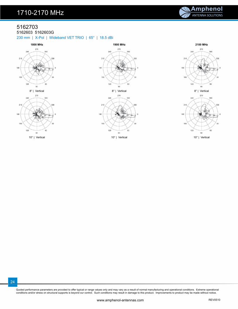
51627035162603 5162603G230 mm | X-Pol | Wideband VET TRIO | 65° | 18.5 dBi
1800 MHz 1900 MHz 2100 MHz
8° | Vertical 8° | Vertical 8° | Vertical
10° | Vertical 10° | Vertical 10° | Vertical
1710-2170 MHz

ANTENNA SOLUTIONS
Quoted performance parameters are provided to offer typical or range values only and may vary as a result of normal manufacturing and operational conditions. Extreme operational conditions and/or stress on structural supports is beyond our control. Such conditions may result in damage to this product. Improvements to product may be made without notice.
REV0510 www.amphenol-antennas.com
25
Electrical Characteristics
Frequency band 1710-2170 MHz
Polarization ±45°
Horizontal beamwidth 65° (-3 dB)
Vertical beamwidth 6° (-3 dB)
Gain 16.4 dBd / 18.5 dBi
Electrical downtilt 4-14°
Impedance 50Ω
VSWR < 1.4:1
Upper sidelobe rejection (20° sector above main beam) > 18 dB typical
Null fi ll (fi rst null below main beam) < 18 dB typical
Isolation between ports > 30 dB
Front-to-Back ratio > 25 dB
IM3 (2x20W carrier) < -153 dBc
Maximum power per port 160 W
Connector(s) 6 ports / 7/16-DIN / Female, Long Neck / Bottom
RET Part Number (one unit per sector) RETU-CA41 for AISG1.1 protocol (3 units included in 5230603) RETU-CG41 for 3GPP/AISG2.0 protocol (3 units included in 5230603G)
Environmental
Operating temperature -40 to +60° C -40 to +140° F
Environmental ETS 300 019
RoHS compliant Yes
Mechanical Characteristics
Total Height (includes 250 mm service area) 1940 mm 76.4 in
Effective Height x Diameter 1565 x 230 mm 61.6 x 9.1 in
Weight 27 kg 59.5 lbs
Survival wind speed 200 km/hr 125 mph
Operational wind speed 160 km/hr 99 mph
Wind load @ 160 km/hr (100 mph) 222 N 50 lbf
Shroud Outdoor plastic, RAL 7035 Grey
Relative directions of internal antennas (sector axis) 0° 120° 240°
Packaging
Packing dimensions 2480 x 350 x 430 mm 97.6 x 13.8 x 16.9 in
Packing weight 57 kg 125.7 lbs
Packing volume 0.373 m3 13.2 ft3
Accessories Part Number Description
Lightning protection kit TRX-LPK Lightning fi nial
Trio extension TRX230-E085-002 Mounting Mast, 85 cm high x 230 mm dia
Trio-Pack (delivered w/non-penetrating platform) Please contact us
5230703 5230603 5230603G
1710-2170 MHz
230 mm | X-Pol | Wideband VET TRIO | 65° | 18.5 dBi
● Tri-sector Wideband antenna, 2 connectors per sector● Variable electrical tilt 4-14°● Very small diameter (230 mm) for low wind load● MET and RET versions, AISG1.1 or 3GPP/AISG2.0● Dual-sector & Single-sector antennas available
Model number reference:Tri-sector Dual-sector Single-sector 5230703 5230702 5230701 Manual Electrical Tilt Antenna5230603 5230602 5230601 Remote Electrical Tilt Antenna, AISG1.15230603G 5230602G 5230601G Remote Electrical Tilt Antenna, 3GPP/AISG2.0
ANTENNA SOLUTIONS
Quoted performance parameters are provided to offer typical or range values only and may vary as a result of normal manufacturing and operational conditions. Extreme operational conditions and/or stress on structural supports is beyond our control. Such conditions may result in damage to this product. Improvements to product may be made without notice.
www.amphenol-antennas.com REV0510
26
52307035230603 5230603G
1710-2170 MHz
230 mm | X-Pol | Wideband VET TRIO | 65° | 18.5 dBi
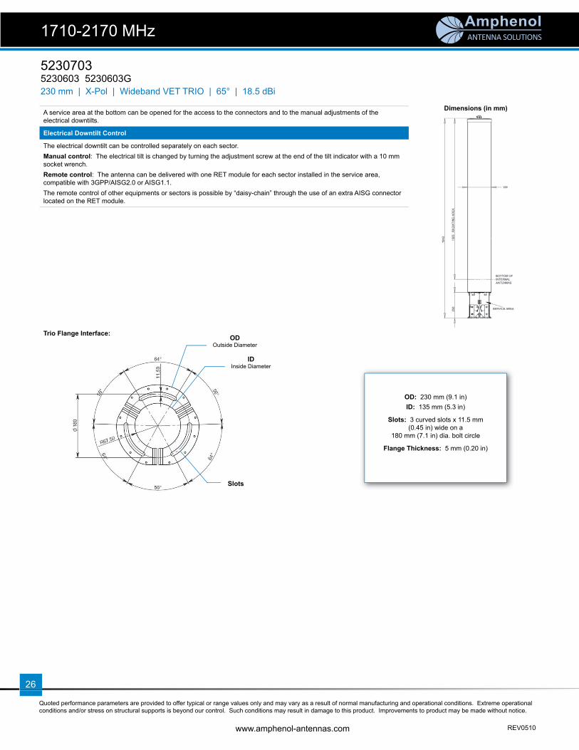
Dimensions (in mm)
Trio Flange Interface:
A service area at the bottom can be opened for the access to the connectors and to the manual adjustments of the electrical downtilts.
Electrical Downtilt Control
The electrical downtilt can be controlled separately on each sector. Manual control: The electrical tilt is changed by turning the adjustment screw at the end of the tilt indicator with a 10 mm socket wrench.Remote control: The antenna can be delivered with one RET module for each sector installed in the service area, compatible with 3GPP/AISG2.0 or AISG1.1.The remote control of other equipments or sectors is possible by “daisy-chain” through the use of an extra AISG connector located on the RET module.
OD: 230 mm (9.1 in)ID: 135 mm (5.3 in)
Slots: 3 curved slots x 11.5 mm (0.45 in) wide on a
180 mm (7.1 in) dia. bolt circle
Flange Thickness: 5 mm (0.20 in)
ODOutside Diameter
IDInside Diameter
Slots

ANTENNA SOLUTIONS
Quoted performance parameters are provided to offer typical or range values only and may vary as a result of normal manufacturing and operational conditions. Extreme operational conditions and/or stress on structural supports is beyond our control. Such conditions may result in damage to this product. Improvements to product may be made without notice.
REV0510 www.amphenol-antennas.com
27
1800 MHz 1900 MHz 2100 MHz
Horizontal Horizontal Horizontal
4° | Vertical 4° | Vertical 4° | Vertical
6° | Vertical 6° | Vertical 6° | Vertical
8° | Vertical 8° | Vertical 8° | Vertical
10° | Vertical 10° | Vertical 10° | Vertical
52307035230603 5230603G
1710-2170 MHz
230 mm | X-Pol | Wideband VET TRIO | 65° | 18.5 dBi
ANTENNA SOLUTIONS
Quoted performance parameters are provided to offer typical or range values only and may vary as a result of normal manufacturing and operational conditions. Extreme operational conditions and/or stress on structural supports is beyond our control. Such conditions may result in damage to this product. Improvements to product may be made without notice.
www.amphenol-antennas.com REV0510
28
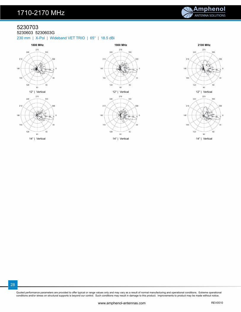
52307035230603 5230603G230 mm | X-Pol | Wideband VET TRIO | 65° | 18.5 dBi
1800 MHz 1900 MHz 2100 MHz
12° | Vertical 12° | Vertical 12° | Vertical
14° | Vertical 14° | Vertical 14° | Vertical
1710-2170 MHz

ANTENNA SOLUTIONS
Quoted performance parameters are provided to offer typical or range values only and may vary as a result of normal manufacturing and operational conditions. Extreme operational conditions and/or stress on structural supports is beyond our control. Such conditions may result in damage to this product. Improvements to product may be made without notice.
REV0510 www.amphenol-antennas.com
29
WB3X072X18x00WB3X072X18M00 WB3X072X18R00
1710-2170 MHz
230 mm | X-Pol | Wideband VET TRIO | 72° | 18.0 dBiModel number options (x):WB3X072X18M00 Manual Electrical Tilt AntennaWB3X072X18R00 Remote Electrical Tilt Antenna
Electrical Characteristics 1710-2170 MHz
Frequency band 1710-1880 MHz 1850-1990 MHz 1900-2170 MHz
Polarization ±45°
Horizontal beamwidth 74° 72° 70°
Vertical beamwidth 6.8° 6.5° 6.2°
Gain 15.0 dBd / 17.1 dBi 15.5 dBd / 17.6 dBi 15.9 dBd / 18.0 dBi
Electrical downtilt 0°-10°
Impedance 50Ω
VSWR < 1.4:1
1st upper side lobe < -13 dB
1st null > -25 dB
Inter-port isolation > 28 dB (> 30 dB typical)
Front-to-Back ratio > 22 dB
Maximum power per port 6 x 200 W
Connector(s) 6 ports / 7/16-DIN / Female / Bottom
RET Type / Part Number 3 x Internal / RETU-EA01
Operating temperature -40 to +60° C -40 to +140° F
Mechanical Characteristics
Overall Dimensions Height x Diameter 1828 x 230 mm 72.0 x 9.1 in
Weight 27.4 kg 60.5 lbs
Survival wind speed 200 km/hr 125 mph
Wind load @ 160 km/hr (100 mph) 645 N 145 lbf
Accessories Part Number Description
Lightning protection kit UNX-LPK Copper air fi nial with 6m (20 ft) cable attached
Flag adapter kit W3X-F 230 mm Trio ball and truck assembly
Mounting mast W3X-M-120 230 mm fl ange welded to a 3m (10 ft) pipe
Trio Flange Interface:
OD: 9.08 in (230.6 mm)ID: 6.25 in (158.8 mm)
Slots: 3 x 0.531 in. (13.5 mm) wide x 30° slots equally spaced on a 7.50 in
(190.5 mm) bolt circle
Flange Thickness: 0.375 in (9.5 mm)
ODOutside Diameter
IDInside Diameter
Slots
ANTENNA SOLUTIONS
Quoted performance parameters are provided to offer typical or range values only and may vary as a result of normal manufacturing and operational conditions. Extreme operational conditions and/or stress on structural supports is beyond our control. Such conditions may result in damage to this product. Improvements to product may be made without notice.
www.amphenol-antennas.com REV0510
30
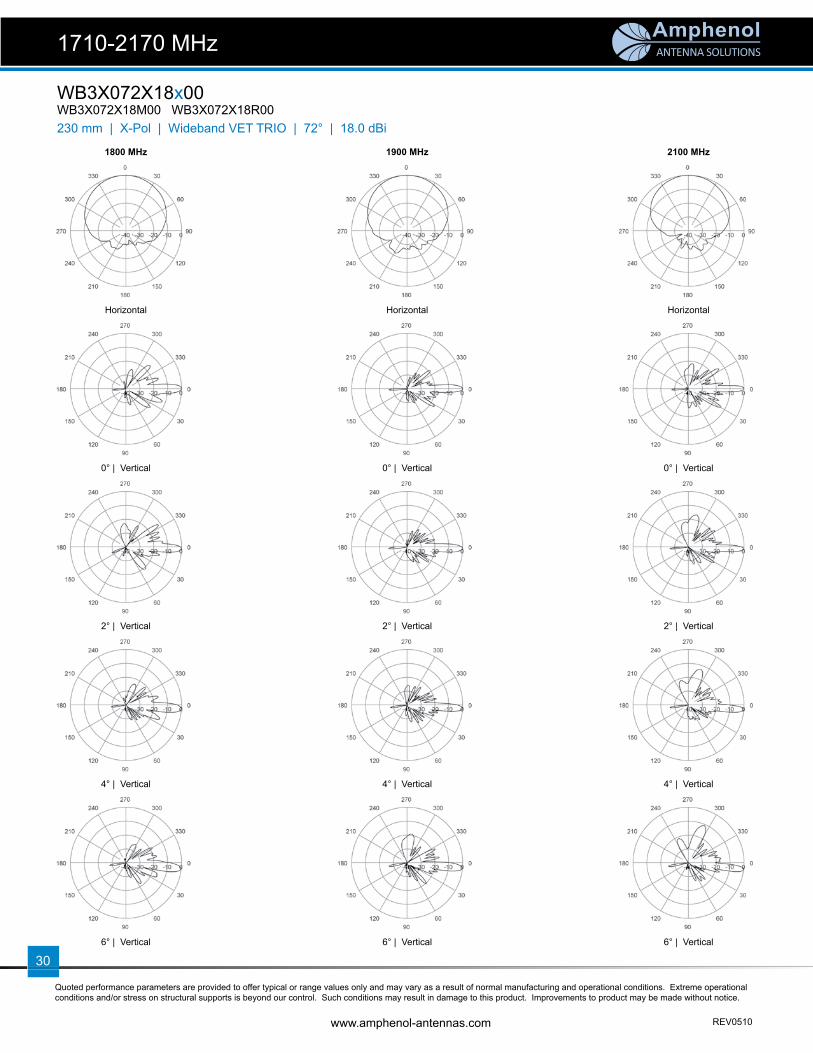
WB3X072X18x00WB3X072X18M00 WB3X072X18R00
1710-2170 MHz
230 mm | X-Pol | Wideband VET TRIO | 72° | 18.0 dBi
1800 MHz 1900 MHz 2100 MHz
Horizontal Horizontal Horizontal
0° | Vertical 0° | Vertical 0° | Vertical
2° | Vertical 2° | Vertical 2° | Vertical
4° | Vertical 4° | Vertical 4° | Vertical
6° | Vertical 6° | Vertical 6° | Vertical

ANTENNA SOLUTIONS
Quoted performance parameters are provided to offer typical or range values only and may vary as a result of normal manufacturing and operational conditions. Extreme operational conditions and/or stress on structural supports is beyond our control. Such conditions may result in damage to this product. Improvements to product may be made without notice.
REV0510 www.amphenol-antennas.com
31
WB3X072X18x00WB3X072X18M00 WB3X072X18R00
1710-2170 MHz
230 mm | X-Pol | Wideband VET TRIO | 72° | 18.0 dBi
1800 MHz 1900 MHz 2100 MHz
8° | Vertical 8° | Vertical 8° | Vertical
10° | Vertical 10° | Vertical 10° | Vertical

32
ANTENNA SOLUTIONS
ANTENNA SOLUTIONS
Quoted performance parameters are provided to offer typical or range values only and may vary as a result of normal manufacturing and operational conditions. Extreme operational conditions and/or stress on structural supports is beyond our control. Such conditions may result in damage to this product. Improvements to product may be made without notice.
REV0510 www.amphenol-antennas.com
33
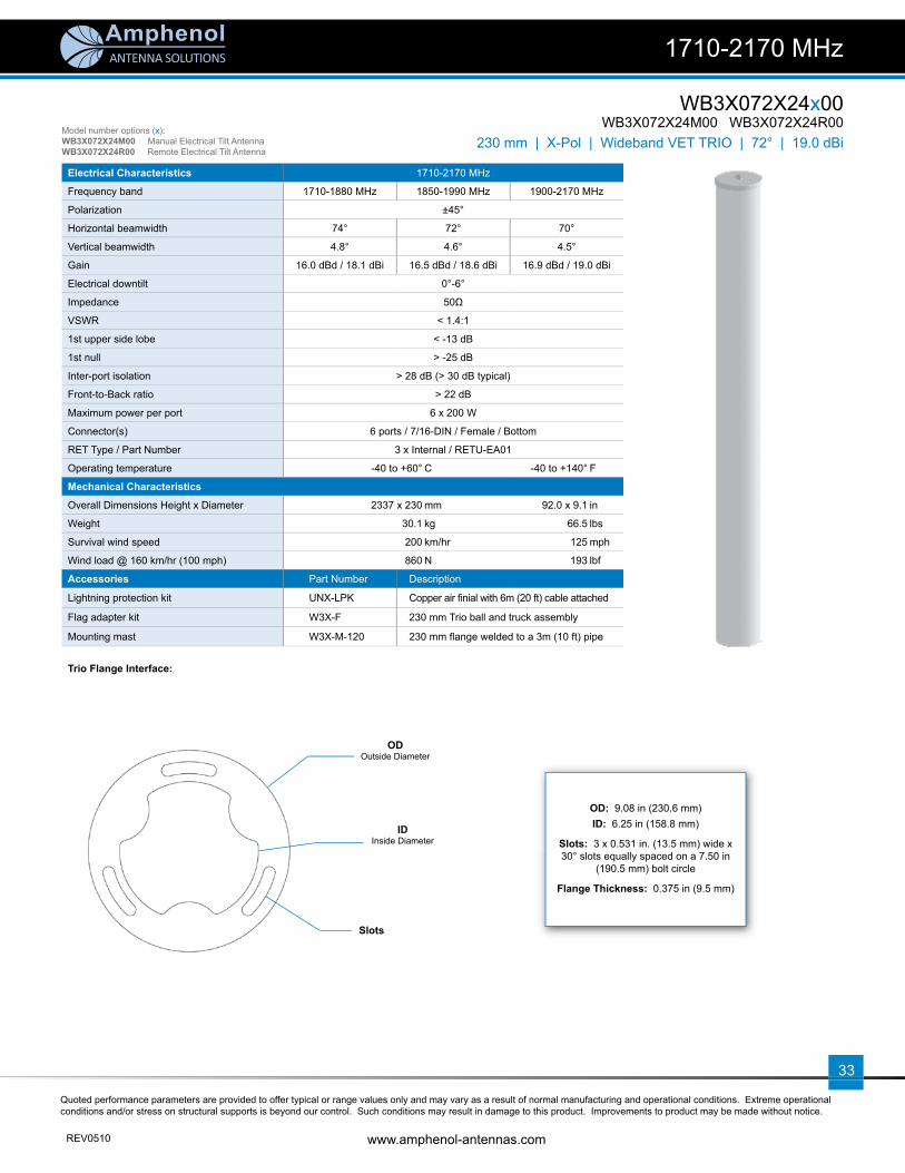
WB3X072X24x00WB3X072X24M00 WB3X072X24R00
1710-2170 MHz
230 mm | X-Pol | Wideband VET TRIO | 72° | 19.0 dBiModel number options (x):WB3X072X24M00 Manual Electrical Tilt AntennaWB3X072X24R00 Remote Electrical Tilt Antenna
Electrical Characteristics 1710-2170 MHz
Frequency band 1710-1880 MHz 1850-1990 MHz 1900-2170 MHz
Polarization ±45°
Horizontal beamwidth 74° 72° 70°
Vertical beamwidth 4.8° 4.6° 4.5°
Gain 16.0 dBd / 18.1 dBi 16.5 dBd / 18.6 dBi 16.9 dBd / 19.0 dBi
Electrical downtilt 0°-6°
Impedance 50Ω
VSWR < 1.4:1
1st upper side lobe < -13 dB
1st null > -25 dB
Inter-port isolation > 28 dB (> 30 dB typical)
Front-to-Back ratio > 22 dB
Maximum power per port 6 x 200 W
Connector(s) 6 ports / 7/16-DIN / Female / Bottom
RET Type / Part Number 3 x Internal / RETU-EA01
Operating temperature -40 to +60° C -40 to +140° F
Mechanical Characteristics
Overall Dimensions Height x Diameter 2337 x 230 mm 92.0 x 9.1 in
Weight 30.1 kg 66.5 lbs
Survival wind speed 200 km/hr 125 mph
Wind load @ 160 km/hr (100 mph) 860 N 193 lbf
Accessories Part Number Description
Lightning protection kit UNX-LPK Copper air fi nial with 6m (20 ft) cable attached
Flag adapter kit W3X-F 230 mm Trio ball and truck assembly
Mounting mast W3X-M-120 230 mm fl ange welded to a 3m (10 ft) pipe
Trio Flange Interface:
OD: 9.08 in (230.6 mm)ID: 6.25 in (158.8 mm)
Slots: 3 x 0.531 in. (13.5 mm) wide x 30° slots equally spaced on a 7.50 in
(190.5 mm) bolt circle
Flange Thickness: 0.375 in (9.5 mm)
ODOutside Diameter
IDInside Diameter
Slots

ANTENNA SOLUTIONS
Quoted performance parameters are provided to offer typical or range values only and may vary as a result of normal manufacturing and operational conditions. Extreme operational conditions and/or stress on structural supports is beyond our control. Such conditions may result in damage to this product. Improvements to product may be made without notice.
www.amphenol-antennas.com REV0510
34
WB3X072X24x00WB3X072X24M00 WB3X072X24R00
1710-2170 MHz
230 mm | X-Pol | Wideband VET TRIO | 72° | 19.0 dBi
1800 MHz 1900 MHz 2100 MHz
Horizontal Horizontal Horizontal
0° | Vertical 0° | Vertical 0° | Vertical
2° | Vertical 2° | Vertical 2° | Vertical
4° | Vertical 4° | Vertical 4° | Vertical
6° | Vertical 6° | Vertical 6° | Vertical

ANTENNA SOLUTIONS
Quoted performance parameters are provided to offer typical or range values only and may vary as a result of normal manufacturing and operational conditions. Extreme operational conditions and/or stress on structural supports is beyond our control. Such conditions may result in damage to this product. Improvements to product may be made without notice.
REV0510 www.amphenol-antennas.com
35
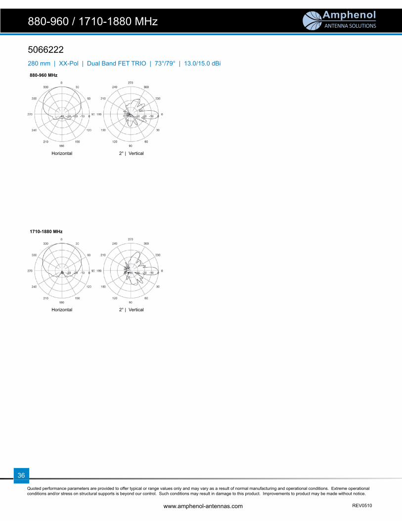
5066222
880-960 / 1710-1880 MHz
280 mm | XX-Pol | Dual Band FET TRIO | 73°/79° | 13.0/15.0 dBi
● Tri-sector dual band (GSM900 / UMTS) antenna
● Features GRP housing and is fl ange mounted at base
● 2° Fixed electrical tilt
Electrical Characteristics
Frequency band 880-960 MHz 1710-1880 MHz
Polarization ±45°
Horizontal beamwidth 73° (± 3°) 79° (± 4°)
Vertical beamwidth 15° (± 2°)
Gain 10.9 dBd / 13.0 dBi 12.9 dBd / 15.0 dBi
Electrical downtilt 2°
Impedance 50Ω
VSWR < 1.4:1
Inter-port isolation > 28 dB > 30 dB
IM3 (2x20W carrier) -110 dBm
Front-to-Back ratio > 22 dB
Maximum power per port 6 x 200 W
Connector(s) 6 ports / 7/16-DIN / Female / Bottom
Mechanical Characteristics
Overall Dimensions Height x Diameter 1365 x 280 mm 53.7 x 11.0 in
Weight 22.0 kg 48.5 lbs
Wind load @ 160 km/hr (100 mph) 400 N 89.9 lbf
MaterialsGRP Cylindrical Shroud,
Colour Goose Gray, Aluminium Flages top & bottom
Trio Flange Interface:
OD: 11.02 in (280 mm)ID: 5.51 in (140 mm)
BCD: 6 x M10 mounting holes equally spaced on a 8.27 in (210 mm) bolt circle
Flange Thickness: 0.393 in (10 mm)
ODOutside Diameter
IDInside Diameter
BCDBolt Circle Diameter
ANTENNA SOLUTIONS
Quoted performance parameters are provided to offer typical or range values only and may vary as a result of normal manufacturing and operational conditions. Extreme operational conditions and/or stress on structural supports is beyond our control. Such conditions may result in damage to this product. Improvements to product may be made without notice.
www.amphenol-antennas.com REV0510
36
5066222
880-960 / 1710-1880 MHz
280 mm | XX-Pol | Dual Band FET TRIO | 73°/79° | 13.0/15.0 dBi
880-960 MHz
Horizontal 2° | Vertical
1710-1880 MHz
Horizontal 2° | Vertical
ANTENNA SOLUTIONS
Quoted performance parameters are provided to offer typical or range values only and may vary as a result of normal manufacturing and operational conditions. Extreme operational conditions and/or stress on structural supports is beyond our control. Such conditions may result in damage to this product. Improvements to product may be made without notice.
REV0510 www.amphenol-antennas.com
37
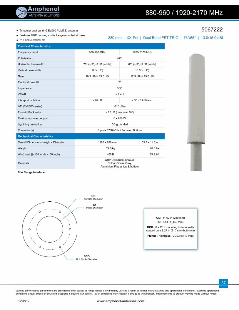
5067222
880-960 / 1920-2170 MHz
280 mm | XX-Pol | Dual Band FET TRIO | 76°/65° | 13.0/15.0 dBi
● Tri-sector dual band (GSM900 / UMTS) antenna
● Features GRP housing and is fl ange mounted at base
● 2° Fixed electrical tilt
Electrical Characteristics
Frequency band 880-960 MHz 1920-2170 MHz
Polarization ±45°
Horizontal beamwidth 76° (± 3°, -3 dB points) 65° (± 3°, -3 dB points)
Vertical beamwidth 17° (± 2°) 10.5° (± 1°)
Gain 10.9 dBd / 13.0 dBi 12.9 dBd / 15.0 dBi
Electrical downtilt 2°
Impedance 50Ω
VSWR < 1.4:1
Inter-port isolation > 28 dB > 30 dB full band
IM3 (2x20W carrier) -110 dBm
Front-to-Back ratio > 25 dB (over rear 80°)
Maximum power per port 6 x 200 W
Lightning protection DC grounded
Connector(s) 6 ports / 7/16-DIN / Female / Bottom
Mechanical Characteristics
Overall Dimensions Height x Diameter 1365 x 280 mm 53.7 x 11.0 in
Weight 22.0 kg 48.5 lbs
Wind load @ 160 km/hr (100 mph) 400 N 89.9 lbf
MaterialsGRP Cylindrical Shroud,
Colour Goose Gray, Aluminium Flages top & bottom
Trio Flange Interface:
OD: 11.02 in (280 mm)ID: 5.51 in (140 mm)
BCD: 6 x M10 mounting holes equally spaced on a 8.27 in (210 mm) bolt circle
Flange Thickness: 0.393 in (10 mm)
ODOutside Diameter
IDInside Diameter
BCDBolt Circle Diameter

ANTENNA SOLUTIONS
Quoted performance parameters are provided to offer typical or range values only and may vary as a result of normal manufacturing and operational conditions. Extreme operational conditions and/or stress on structural supports is beyond our control. Such conditions may result in damage to this product. Improvements to product may be made without notice.
www.amphenol-antennas.com REV0510
38
5067222
880-960 / 1920-2170 MHz
280 mm | XX-Pol | Dual Band FET TRIO | 76°/65° | 13.0/15.0 dBi
880-960 MHz
Horizontal 2° | Vertical
1920-2170 MHz
Horizontal 2° | Vertical

ANTENNA SOLUTIONS
Quoted performance parameters are provided to offer typical or range values only and may vary as a result of normal manufacturing and operational conditions. Extreme operational conditions and/or stress on structural supports is beyond our control. Such conditions may result in damage to this product. Improvements to product may be made without notice.
REV0510 www.amphenol-antennas.com
39
Electrical Characteristics
Frequency band 1710-2170 MHz
Polarization ±45°
Horizontal beamwidth 65° (-3 dB)
Vertical beamwidth 7° (-3 dB)
Gain 15.4 dBd / 17.5 dBi
Electrical downtilt 2-14°
Impedance 50Ω
VSWR < 1.4:1
Upper sidelobe rejection (20° sector above main beam) > 18 dB typical
Null fi ll (fi rst null below main beam) < 22 dB typical
Isolation between ports > 30 dB
Front-to-Back ratio > 25 dB
IM3 (2x20W carrier) < -153 dBc
Maximum power per port 160 W
Connector(s) 6 ports / 7/16-DIN / Female, Long Neck / Bottom
RET Part Number (one unit per sector) RETU-CA51 for AISG1.1 protocol (3 units included in 5176803) RETU-CG51 for 3GPP/AISG2.0 protocol (3 units included in 5176803G)
Environmental
Operating temperature -40 to +60° C -40 to +140° F
Environmental ETS 300 019
RoHS compliant Yes
Mechanical Characteristics
Total Height (includes 250 mm service area) 1710 mm 67.3 in
Effective Height x Diameter 1332 x 310 mm 52.4 x 12.2 in
Weight 32 kg 70.5 lbs
Survival wind speed 200 km/hr 125 mph
Operational wind speed 160 km/hr 99 mph
Wind load @ 160 km/hr (100 mph) 268 N 60.2 lbf
Shroud Outdoor plastic, RAL 7035 Grey
Relative directions of internal antennas (sector axis) 0° (±15°) 120° (±15°) 240° (±15°)
Packaging
Packing dimensions 2480 x 450 x 510 mm 97.6 x 17.7 x 20.1 in
Packing weight 75 kg 165.3 lbs
Packing volume 0.632 m3 22.3 ft3
Accessories Part Number Description
Lightning protection kit TRX-LPK Lightning fi nial
Trio extension TRX310-E085-001TRX310-E085-002*
Mounting Mast, 85 cm high x 310 mm diaMounting Mast, 85 cm high x 310 mm dia
*shroud stops 20 cm above bottom fl ange for cables out on the side
Trio-Pack (delivered w/non-penetrating platform) Please contact us
5176903 5176803 5176803G
1710-2170 MHz
310 mm | X-Pol | Wideband VET TRIO | 65° | 17.5 dBi
● Tri-sector Wideband antenna, 2 connectors per sector● Variable electrical tilt 2-14°● Independent azimuth panning ±15° on each sector● Very small diameter (310 mm) for low wind load● MET and RET versions, AISG1.1 or 3GPP/AISG2.0● Dual-sector & Single-sector antennas available
Model number reference:Tri-sector Dual-sector Single-sector 5176903 5176902 5176901 Manual Electrical Tilt Antenna5176803 5176802 5176801 Remote Electrical Tilt Antenna, AISG1.15176803G 5176802G 5176801G Remote Electrical Tilt Antenna, 3GPP/AISG2.0
1710-2170 MHz

ANTENNA SOLUTIONS
Quoted performance parameters are provided to offer typical or range values only and may vary as a result of normal manufacturing and operational conditions. Extreme operational conditions and/or stress on structural supports is beyond our control. Such conditions may result in damage to this product. Improvements to product may be made without notice.
www.amphenol-antennas.com REV0510
40
51769035176803 5176803G
1710-2170 MHz
310 mm | X-Pol | Wideband VET TRIO | 65° | 17.5 dBi
Dimensions (in mm)
Trio Flange Interface:
A service area at the bottom can be opened for the access to the connectors and to the manual adjustments of the electrical downtilts and the azimuth panning.
Electrical Downtilt Control
The electrical downtilt can be controlled separately on each sector. Manual control: The electrical tilt is changed by turning the adjustment screw at the end of the tilt indicator with a 10 mm socket wrench.Remote control: The antenna can be delivered with one RET module for each sector installed in the service area, compatible with 3GPP/AISG2.0 or AISG1.1.The remote control of other equipments or sectors is possible by “daisy-chain” through the use of an extra AISG connector located on the RET module.
Azimuth Adjustment
The azimuth pointing direction of each sector can be adjusted in a ±15° range from its nominal direction, independently for each sector. The azimuth direction is changed by turning the adjustment screw at the end of the azimuth indicator with a 10 mm socket wrench.
OD: 310 mm (12.2 in)ID: 180 mm (7.1 in)
Slots: 6 curved slots x 11.5 mm (0.45 in) wide on a
260 mm (10.2 in) dia. bolt circle
Flange Thickness: 5 mm (0.20 in)
ODOutside Diameter
IDInside Diameter
Slots

ANTENNA SOLUTIONS
Quoted performance parameters are provided to offer typical or range values only and may vary as a result of normal manufacturing and operational conditions. Extreme operational conditions and/or stress on structural supports is beyond our control. Such conditions may result in damage to this product. Improvements to product may be made without notice.
REV0510 www.amphenol-antennas.com
41
1800 MHz 1900 MHz 2100 MHz
Horizontal Horizontal Horizontal
2° | Vertical 2° | Vertical 2° | Vertical
4° | Vertical 4° | Vertical 4° | Vertical
6° | Vertical 6° | Vertical 6° | Vertical
8° | Vertical 8° | Vertical 8° | Vertical
51769035176803 5176803G
1710-2170 MHz
310 mm | X-Pol | Wideband VET TRIO | 65° | 17.5 dBi

ANTENNA SOLUTIONS
Quoted performance parameters are provided to offer typical or range values only and may vary as a result of normal manufacturing and operational conditions. Extreme operational conditions and/or stress on structural supports is beyond our control. Such conditions may result in damage to this product. Improvements to product may be made without notice.
www.amphenol-antennas.com REV0510
42
1800 MHz 1900 MHz 2100 MHz
10° | Vertical 10° | Vertical 10° | Vertical
12° | Vertical 12° | Vertical 12° | Vertical
14° | Vertical 14° | Vertical 14° | Vertical
51769035176803 5176803G310 mm | X-Pol | Wideband VET TRIO | 65° | 17.5 dBi
1710-2170 MHz

ANTENNA SOLUTIONS
Quoted performance parameters are provided to offer typical or range values only and may vary as a result of normal manufacturing and operational conditions. Extreme operational conditions and/or stress on structural supports is beyond our control. Such conditions may result in damage to this product. Improvements to product may be made without notice.
REV0510 www.amphenol-antennas.com
43
5162903 5162803 5162803G
1710-2170 MHz
310 mm | X-Pol | Wideband VET TRIO | 65° | 18.5 dBi
Electrical Characteristics
Frequency band 1710-2170 MHz
Polarization ±45°
Horizontal beamwidth 65° (-3 dB)
Vertical beamwidth 6° (-3 dB)
Gain 16.4 dBd / 18.5 dBi
Electrical downtilt 0-10°
Impedance 50Ω
VSWR < 1.4:1
Upper sidelobe rejection (20° sector above main beam) > 18 dB typical
Null fi ll (fi rst null below main beam) < 18 dB typical
Isolation between ports > 30 dB
Front-to-Back ratio > 25 dB
IM3 (2x20W carrier) < -153 dBc
Maximum power per port 160 W
Connector(s) 6 ports / 7/16-DIN / Female, Long Neck / Bottom
RET Part Number (one unit per sector) RETU-CA51 for AISG1.1 protocol (3 units included in 5162803) RETU-CG51 for 3GPP/AISG2.0 protocol (3 units included in 5162803G)
Environmental
Operating temperature -40 to +60° C -40 to +140° F
Environmental ETS 300 019
RoHS compliant Yes
Mechanical Characteristics
Total Height (includes 250 mm service area) 1990 mm 78.3 in
Effective Height x Diameter 1590 x 310 mm 62.6 x 12.2 in
Weight 37 kg 81.6 lbs
Survival wind speed 200 km/hr 125 mph
Operational wind speed 160 km/hr 99 mph
Wind load @ 160 km/hr (100 mph) 252 N 56.7 lbf
Shroud Outdoor plastic, RAL 7035 Grey
Relative directions of internal antennas (sector axis) 0° (±15°) 120° (±15°) 240° (±15°)
Packaging
Packing dimensions 2480 x 450 x 510 mm 97.6 x 17.7 x 20.1 in
Packing weight 79 kg 174.2 lbs
Packing volume 0.569 m3 20.1 ft3
Accessories Part Number Description
Lightning protection kit TRX-LPK Lightning fi nial
Trio extension TRX310-E085-001TRX310-E085-002*
Mounting Mast, 85 cm high x 310 mm diaMounting Mast, 85 cm high x 310 mm dia
*shroud stops 20 cm above bottom fl ange for cables out on the side
Trio-Pack (delivered w/non-penetrating platform) Please contact us
● Tri-sector Wideband antenna, 2 connectors per sector● Variable electrical tilt 0-10°● Independent azimuth panning ±15° on each sector● Very small diameter (310 mm) for low wind load● MET and RET versions, AISG1.1 or 3GPP/AISG2.0● Dual-sector & Single-sector antennas available
Model number reference:Tri-sector Dual-sector Single-sector 5162903 5162902 5162901 Manual Electrical Tilt Antenna5162803 5162802 5162801 Remote Electrical Tilt Antenna, AISG1.15162803G 5162802G 5162801G Remote Electrical Tilt Antenna, 3GPP/AISG2.0

ANTENNA SOLUTIONS
Quoted performance parameters are provided to offer typical or range values only and may vary as a result of normal manufacturing and operational conditions. Extreme operational conditions and/or stress on structural supports is beyond our control. Such conditions may result in damage to this product. Improvements to product may be made without notice.
www.amphenol-antennas.com REV0510
44
51629035162803 5162803G
1710-2170 MHz
310 mm | X-Pol | Wideband VET TRIO | 65° | 18.5 dBi
Dimensions (in mm)
Trio Flange Interface:
OD: 310 mm (12.2 in)ID: 180 mm (7.1 in)
Slots: 6 curved slots x 11.5 mm (0.45 in) wide on a
260 mm (10.2 in) dia. bolt circle
Flange Thickness: 5 mm (0.20 in)
A service area at the bottom can be opened for the access to the connectors and to the manual adjustments of the electrical downtilts and the azimuth panning.
Electrical Downtilt Control
The electrical downtilt can be controlled separately on each sector. Manual control: The electrical tilt is changed by turning the adjustment screw at the end of the tilt indicator with a 10 mm socket wrench.Remote control: The antenna can be delivered with one RET module for each sector installed in the service area, compatible with 3GPP/AISG2.0 or AISG1.1.The remote control of other equipments or sectors is possible by “daisy-chain” through the use of an extra AISG connector located on the RET module.
Azimuth Adjustment
The azimuth pointing direction of each sector can be adjusted in a ±15° range from its nominal direction, independently for each sector. The azimuth direction is changed by turning the adjustment screw at the end of the azimuth indicator with a 10 mm socket wrench.
ODOutside Diameter
IDInside Diameter
Slots

ANTENNA SOLUTIONS
Quoted performance parameters are provided to offer typical or range values only and may vary as a result of normal manufacturing and operational conditions. Extreme operational conditions and/or stress on structural supports is beyond our control. Such conditions may result in damage to this product. Improvements to product may be made without notice.
REV0510 www.amphenol-antennas.com
45
1800 MHz 1900 MHz 2100 MHz
Horizontal Horizontal Horizontal
0° | Vertical 0° | Vertical 0° | Vertical
2° | Vertical 2° | Vertical 2° | Vertical
4° | Vertical 4° | Vertical 4° | Vertical
6° | Vertical 6° | Vertical 6° | Vertical
51629035162803 5162803G
1710-2170 MHz
310 mm | X-Pol | Wideband VET TRIO | 65° | 18.5 dBi

ANTENNA SOLUTIONS
Quoted performance parameters are provided to offer typical or range values only and may vary as a result of normal manufacturing and operational conditions. Extreme operational conditions and/or stress on structural supports is beyond our control. Such conditions may result in damage to this product. Improvements to product may be made without notice.
www.amphenol-antennas.com REV0510
46
51629035162803 5162803G
1710-2170 MHz
310 mm | X-Pol | Wideband VET TRIO | 65° | 18.5 dBi
1800 MHz 1900 MHz 2100 MHz
8° | Vertical 8° | Vertical 8° | Vertical
10° | Vertical 10° | Vertical 10° | Vertical

ANTENNA SOLUTIONS
Quoted performance parameters are provided to offer typical or range values only and may vary as a result of normal manufacturing and operational conditions. Extreme operational conditions and/or stress on structural supports is beyond our control. Such conditions may result in damage to this product. Improvements to product may be made without notice.
REV0510 www.amphenol-antennas.com
47
Electrical Characteristics
Frequency band 1710-2170 MHz
Polarization ±45°
Horizontal beamwidth 65° (-3 dB)
Vertical beamwidth 6° (-3 dB)
Gain 16.4 dBd / 18.5 dBi
Electrical downtilt 4-14°
Impedance 50Ω
VSWR < 1.4:1
Upper sidelobe rejection (20° sector above main beam) > 18 dB typical
Null fi ll (fi rst null below main beam) < 18 dB typical
Isolation between ports > 30 dB
Front-to-Back ratio > 25 dB
IM3 (2x20W carrier) < -153 dBc
Maximum power per port 160 W
Connector(s) 6 ports / 7/16-DIN / Female, Long Neck / Bottom
RET Part Number (one unit per sector) RETU-CA51 for AISG1.1 protocol (3 units included in 5230803) RETU-CG51 for 3GPP/AISG2.0 protocol (3 units included in 5230803G)
Environmental
Operating temperature -40 to +60° C -40 to +140° F
Environmental ETS 300 019
RoHS compliant Yes
Mechanical Characteristics
Total Height (includes 250 mm service area) 1990 mm 78.3 in
Effective Height x Diameter 1590 x 310 mm 62.6 x 12.2 in
Weight 37 kg 81.6 lbs
Survival wind speed 200 km/hr 125 mph
Operational wind speed 160 km/hr 99 mph
Wind load @ 160 km/hr (100 mph) 252 N 56.7 lbf
Shroud Outdoor plastic, RAL 7035 Grey
Relative directions of internal antennas (sector axis) 0° (±15°) 120° (±15°) 240° (±15°)
Packaging
Packing dimensions 2480 x 450 x 510 mm 97.6 x 17.7 x 20.1 in
Packing weight 81 kg 178.6 lbs
Packing volume 0.569 m3 20.1 ft3
Accessories Part Number Description
Lightning protection kit TRX-LPK Lightning fi nial
Trio extension TRX310-E085-001TRX310-E085-002*
Mounting Mast, 85 cm high x 310 mm diaMounting Mast, 85 cm high x 310 mm dia
*shroud stops 20 cm above bottom fl ange for cables out on the side
Trio-Pack (delivered w/non-penetrating platform) Please contact us
5230903 5230803 5230803G
1710-2170 MHz
310 mm | X-Pol | Wideband VET TRIO | 65° | 18.5 dBi
● Tri-sector Wideband antenna, 2 connectors per sector● Variable electrical tilt 4-14°● Independent azimuth panning ±15° on each sector● Very small diameter (310 mm) for low wind load● MET and RET versions, AISG1.1 or 3GPP/AISG2.0● Dual-sector & Single-sector antennas available
Model number reference:Tri-sector Dual-sector Single-sector 5230903 5230902 5230901 Manual Electrical Tilt Antenna5230803 5230802 5230801 Remote Electrical Tilt Antenna, AISG1.15230803G 5230802G 5230801G Remote Electrical Tilt Antenna, 3GPP/AISG2.0

ANTENNA SOLUTIONS
Quoted performance parameters are provided to offer typical or range values only and may vary as a result of normal manufacturing and operational conditions. Extreme operational conditions and/or stress on structural supports is beyond our control. Such conditions may result in damage to this product. Improvements to product may be made without notice.
www.amphenol-antennas.com REV0510
48
52309035230803 5230803G
1710-2170 MHz
310 mm | X-Pol | Wideband VET TRIO | 65° | 18.5 dBi
Dimensions (in mm)
Trio Flange Interface:
OD: 310 mm (12.2 in)ID: 180 mm (7.1 in)
Slots: 6 curved slots x 11.5 mm (0.45 in) wide on a
260 mm (10.2 in) dia. bolt circle
Flange Thickness: 5 mm (0.20 in)
A service area at the bottom can be opened for the access to the connectors and to the manual adjustments of the electrical downtilts and the azimuth panning.
Electrical Downtilt Control
The electrical downtilt can be controlled separately on each sector. Manual control: The electrical tilt is changed by turning the adjustment screw at the end of the tilt indicator with a 10 mm socket wrench.Remote control: The antenna can be delivered with one RET module for each sector installed in the service area, compatible with 3GPP/AISG2.0 or AISG1.1.The remote control of other equipments or sectors is possible by “daisy-chain” through the use of an extra AISG connector located on the RET module.
Azimuth Adjustment
The azimuth pointing direction of each sector can be adjusted in a ±15° range from its nominal direction, independently for each sector. The azimuth direction is changed by turning the adjustment screw at the end of the azimuth indicator with a 10 mm socket wrench.
ODOutside Diameter
IDInside Diameter
Slots

ANTENNA SOLUTIONS
Quoted performance parameters are provided to offer typical or range values only and may vary as a result of normal manufacturing and operational conditions. Extreme operational conditions and/or stress on structural supports is beyond our control. Such conditions may result in damage to this product. Improvements to product may be made without notice.
REV0510 www.amphenol-antennas.com
49
1800 MHz 1900 MHz 2100 MHz
Horizontal Horizontal Horizontal
4° | Vertical 4° | Vertical 4° | Vertical
6° | Vertical 6° | Vertical 6° | Vertical
8° | Vertical 8° | Vertical 8° | Vertical
10° | Vertical 10° | Vertical 10° | Vertical
52309035230803 5230803G
1710-2170 MHz
310 mm | X-Pol | Wideband VET TRIO | 65° | 18.5 dBi

ANTENNA SOLUTIONS
Quoted performance parameters are provided to offer typical or range values only and may vary as a result of normal manufacturing and operational conditions. Extreme operational conditions and/or stress on structural supports is beyond our control. Such conditions may result in damage to this product. Improvements to product may be made without notice.
www.amphenol-antennas.com REV0510
50
52309035230803 5230803G
1710-2170 MHz
310 mm | X-Pol | Wideband VET TRIO | 65° | 18.5 dBi
1800 MHz 1900 MHz 2100 MHz
12° | Vertical 12° | Vertical 12° | Vertical
14° | Vertical 14° | Vertical 14° | Vertical

ANTENNA SOLUTIONS
Quoted performance parameters are provided to offer typical or range values only and may vary as a result of normal manufacturing and operational conditions. Extreme operational conditions and/or stress on structural supports is beyond our control. Such conditions may result in damage to this product. Improvements to product may be made without notice.
REV0510 www.amphenol-antennas.com
51
5863703 5863603 5863603G
880-960 / 1710-2170 MHz
310 mm | XX-Pol | Dual Band VET TRIO | 65° | 16.5/18.0 dBi
Electrical Characteristics 880-960 MHz 1710-2170 MHz
Frequency band 880-960 MHz 1710-1880 MHz 1900-2170 MHz
Polarization ±45° ±45°
Horizontal beamwidth (-3 dB) 65° 65° 64°
Vertical beamwidth (-3 dB) 9° 6° 6°
Gain tilt 0° tilt 5° tilt 10°
16.0...16.5 dBi16.0...16.5 dBi15.9...16.4 dBi
17.3...17.6 dBi17.2...17.4 dBi17.2...17.3 dBi
17.6...18.1 dBi17.4...17.9 dBi17.3...17.7 dBi
Electrical downtilt 0-10° 0-10°
Impedance 50Ω 50Ω
VSWR < 1.4:1 < 1.4:1
Upper sidelobe rejection (20° sector above main beam) 18 dB typical 18 dB typical
Isolation between ports > 30 dB > 30 dB
Isolation between bands 45 dB typical 45 dB typical
Front-to-Back ratio > 30 dB > 30 dB
IM3 (2x20W carrier) < -110 dBm < -110 dBm
Maximum power per port 200 W 160 W
Connector(s) 12 ports / 7/16-DIN / Female, Long Neck / Bottom
RET Part Number (one unit per sector) MDCU-A0001 for AISG1.1 protocol (3 units included in 5863603) MDCU-G0001 for 3GPP/AISG2.0 protocol (3 units included in 5863603G)
We can provide a RET module with separate control of the motors to allow dual-operators or dual-technology control. Please contact us.
Environmental
Operating temperature -40 to +60° C -40 to +140° F
Environmental ETS 300 019
RoHS compliant Yes
Mechanical Characteristics
Total Height (includes 250 mm service area) 2291 mm 90.2 in
Effective Height x Diameter 1900 x 310 mm 74.8 x 12.2 in
Weight 45 kg 99.2 lbs
Survival wind speed 200 km/hr 125 mph
Operational wind speed 160 km/hr 99 mph
Wind load @ 160 km/hr (100 mph) 312 N 70.1 lbf
Shroud Outdoor plastic, RAL 7035 Grey
Accessories Part Number Description
Lightning protection kit TRX-LPK Lightning fi nial
Trio extension TRX310-E085-001TRX310-E085-002*
Mounting Mast, 85 cm high x 310 mm diaMounting Mast, 85 cm high x 310 mm dia
*shroud stops 20 cm above bottom fl ange for cables out on the side
Trio-Pack (delivered w/non-penetrating platform) Please contact us
● Tri-sector Dual Band antenna, 4 connectors per sector● Independent tilt on each band 0-10° / 0-10°● Very small diameter (310 mm) for low wind load● MET and RET versions, AISG1.1 or 3GPP/AISG2.0● Single RET module per sector to control all tilt angles● Dual-sector & Single-sector antennas available
Model number reference:Tri-sector Dual-sector Single-sector 5863703 5863702 5863701 Manual Electrical Tilt Antenna5863603 5863602 5863601 Remote Electrical Tilt Antenna, AISG1.15863603G 5863602G 5863601G Remote Electrical Tilt Antenna, 3GPP/AISG2.0

ANTENNA SOLUTIONS
Quoted performance parameters are provided to offer typical or range values only and may vary as a result of normal manufacturing and operational conditions. Extreme operational conditions and/or stress on structural supports is beyond our control. Such conditions may result in damage to this product. Improvements to product may be made without notice.
www.amphenol-antennas.com REV0510
52
58637035863603 5863603G
880-960 / 1710-2170 MHz
310 mm | XX-Pol | Dual Band VET TRIO | 65° | 16.5/18.0 dBi
Dimensions (in mm)
Trio Flange Interface:
OD: 310 mm (12.2 in)ID: 180 mm (7.1 in)
Slots: 6 curved slots x 11.5 mm (0.45 in) wide on a
260 mm (10.2 in) dia. bolt circle
Flange Thickness: 5 mm (0.20 in)
Access Ports Description (Connectors)
Each sector has 4 connectors located inside the service area and marked with colour rings. A service area at the bottom can be opened for the access to the connectors and to the manual adjustments of the electrical downtilts.
Low Band 880-960 MHz ports RED rings 2 x 7/16-DIN Female Long Neck
High band 1710-2170 MHz ports (wide band) BLUE rings 2 x 7/16-DIN Female Long Neck
Electrical Downtilt Control
Electrical downtilt can be controlled separately for Low Band and High Band.The two tilt indicators are covered by a removable transparent cap.Manual control: A coloured knob at the end of the tilt indicator allows change of the tilt without need for a tool. Knob colour is identical to connector colours as defi ned above. To access the knob, the cap is removed by turning it counter clockwise. It is re-installed by opposite rotation.Remote control: The remote control of the electrical tilt is managed by a module (MDCU) totally inserted at the bottom of the antenna. One single module controls individually the tilt of each band (no need of daisy chain cables between the bands). For RET control, the transparent cap must be in place and locked. This module does not add any additional length at the bottom of the antenna. The tilt angle indicator stays always visible and the antenna still has manual tilt control (manual override).
ODOutside Diameter
IDInside Diameter
Slots

ANTENNA SOLUTIONS
Quoted performance parameters are provided to offer typical or range values only and may vary as a result of normal manufacturing and operational conditions. Extreme operational conditions and/or stress on structural supports is beyond our control. Such conditions may result in damage to this product. Improvements to product may be made without notice.
REV0510 www.amphenol-antennas.com
53
880-960 MHz
Horizontal 0° | Vertical 2° | Vertical 4° | Vertical 6° | Vertical
8° | Vertical 10° | Vertical
1710-2170 MHz
Horizontal 0° | Vertical 2° | Vertical 4° | Vertical 6° | Vertical
8° | Vertical 10° | Vertical
880-960 / 1710-2170 MHz
58637035863603 5863603G
310 mm | XX-Pol | Dual Band VET TRIO | 65° | 16.5/18.0 dBi

54
ANTENNA SOLUTIONS
ANTENNA SOLUTIONS
Quoted performance parameters are provided to offer typical or range values only and may vary as a result of normal manufacturing and operational conditions. Extreme operational conditions and/or stress on structural supports is beyond our control. Such conditions may result in damage to this product. Improvements to product may be made without notice.
REV0510 www.amphenol-antennas.com
55
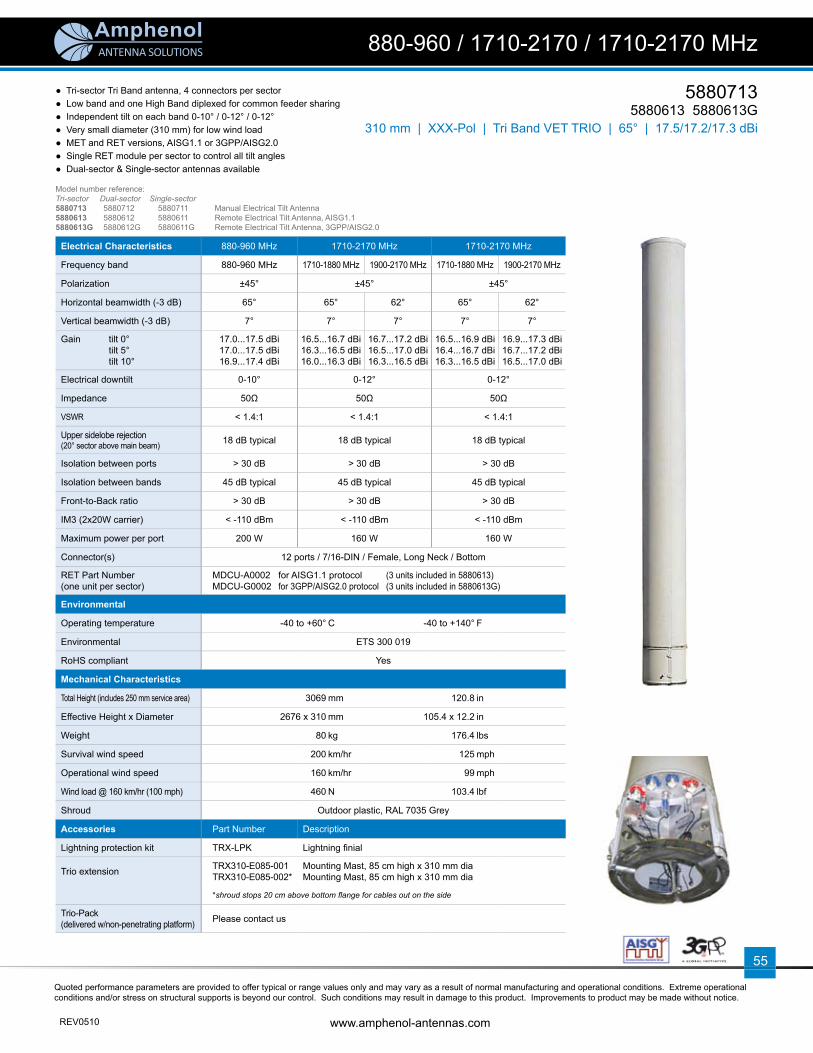
Electrical Characteristics 880-960 MHz 1710-2170 MHz 1710-2170 MHz
Frequency band 880-960 MHz 1710-1880 MHz 1900-2170 MHz 1710-1880 MHz 1900-2170 MHz
Polarization ±45° ±45° ±45°
Horizontal beamwidth (-3 dB) 65° 65° 62° 65° 62°
Vertical beamwidth (-3 dB) 7° 7° 7° 7° 7°
Gain tilt 0° tilt 5° tilt 10°
17.0...17.5 dBi17.0...17.5 dBi16.9...17.4 dBi
16.5...16.7 dBi16.3...16.5 dBi16.0...16.3 dBi
16.7...17.2 dBi16.5...17.0 dBi16.3...16.5 dBi
16.5...16.9 dBi16.4...16.7 dBi16.3...16.5 dBi
16.9...17.3 dBi16.7...17.2 dBi16.5...17.0 dBi
Electrical downtilt 0-10° 0-12° 0-12°
Impedance 50Ω 50Ω 50Ω
VSWR < 1.4:1 < 1.4:1 < 1.4:1
Upper sidelobe rejection (20° sector above main beam) 18 dB typical 18 dB typical 18 dB typical
Isolation between ports > 30 dB > 30 dB > 30 dB
Isolation between bands 45 dB typical 45 dB typical 45 dB typical
Front-to-Back ratio > 30 dB > 30 dB > 30 dB
IM3 (2x20W carrier) < -110 dBm < -110 dBm < -110 dBm
Maximum power per port 200 W 160 W 160 W
Connector(s) 12 ports / 7/16-DIN / Female, Long Neck / Bottom
RET Part Number (one unit per sector)
MDCU-A0002 for AISG1.1 protocol (3 units included in 5880613) MDCU-G0002 for 3GPP/AISG2.0 protocol (3 units included in 5880613G)
Environmental
Operating temperature -40 to +60° C -40 to +140° F
Environmental ETS 300 019
RoHS compliant Yes
Mechanical Characteristics
Total Height (includes 250 mm service area) 3069 mm 120.8 in
Effective Height x Diameter 2676 x 310 mm 105.4 x 12.2 in
Weight 80 kg 176.4 lbs
Survival wind speed 200 km/hr 125 mph
Operational wind speed 160 km/hr 99 mph
Wind load @ 160 km/hr (100 mph) 460 N 103.4 lbf
Shroud Outdoor plastic, RAL 7035 Grey
Accessories Part Number Description
Lightning protection kit TRX-LPK Lightning fi nial
Trio extension TRX310-E085-001TRX310-E085-002*
Mounting Mast, 85 cm high x 310 mm diaMounting Mast, 85 cm high x 310 mm dia
*shroud stops 20 cm above bottom fl ange for cables out on the side
Trio-Pack (delivered w/non-penetrating platform) Please contact us
5880713 5880613 5880613G
880-960 / 1710-2170 / 1710-2170 MHz
310 mm | XXX-Pol | Tri Band VET TRIO | 65° | 17.5/17.2/17.3 dBi
● Tri-sector Tri Band antenna, 4 connectors per sector● Low band and one High Band diplexed for common feeder sharing ● Independent tilt on each band 0-10° / 0-12° / 0-12°● Very small diameter (310 mm) for low wind load● MET and RET versions, AISG1.1 or 3GPP/AISG2.0● Single RET module per sector to control all tilt angles● Dual-sector & Single-sector antennas available
Model number reference:Tri-sector Dual-sector Single-sector 5880713 5880712 5880711 Manual Electrical Tilt Antenna5880613 5880612 5880611 Remote Electrical Tilt Antenna, AISG1.15880613G 5880612G 5880611G Remote Electrical Tilt Antenna, 3GPP/AISG2.0

ANTENNA SOLUTIONS
Quoted performance parameters are provided to offer typical or range values only and may vary as a result of normal manufacturing and operational conditions. Extreme operational conditions and/or stress on structural supports is beyond our control. Such conditions may result in damage to this product. Improvements to product may be made without notice.
www.amphenol-antennas.com REV0510
56
58807135880613 5880613G
880-960 / 1710-2170 / 1710-2170 MHz
310 mm | XXX-Pol | Tri Band VET TRIO | 65° | 17.5/17.2/17.3 dBi
Trio Flange Interface:
Trio Flange Interface:
OD: 310 mm (12.2 in)ID: 180 mm (7.1 in)
Slots: 6 curved slots x 11.5 mm (0.45 in) wide on a
260 mm (10.2 in) dia. bolt circle
Flange Thickness: 5 mm (0.20 in)
Access Ports Description (Connectors)
Each sector has 4 connectors located inside the service area and marked with colour rings. Low band Red and High band White are diplexed and share the same connectors. A service area at the bottom can be opened for the access to the connectors and to the manual adjustments of the electrical downtilts.
Low Band 880-960 MHz ports RED rings2 x 7/16-DIN Female Long Neck
High Band 1710-2170 MHz ports (top array) WHITE rings
High Band 1710-2170 MHz ports (bottom array) BLUE rings 2 x 7/16-DIN Female Long Neck
Electrical Downtilt Control
Electrical downtilt can be controlled separately for Low Band, High Band White and High Band Blue.The three tilt indicators are covered by a removable transparent cap.Manual control: A coloured knob at the end of the tilt indicator allows change of the tilt without need for a tool. Knob colour is identical to connector colours as defi ned above. To access the knob, the cap is removed by turning it counter clockwise. It is re-installed by opposite rotation.Remote control: The remote control of the electrical tilt is managed by a module (MDCU) totally inserted at the bottom of the antenna. One single module controls individually the tilt of each band (no need of daisy chain cables between the bands). For RET control, the transparent cap must be in place and locked. This module does not add any additional length at the bottom of the antenna. The tilt angle indicator stays always visible and the antenna still has manual tilt control (manual override).
ODOutside Diameter
IDInside Diameter
Slots

ANTENNA SOLUTIONS
Quoted performance parameters are provided to offer typical or range values only and may vary as a result of normal manufacturing and operational conditions. Extreme operational conditions and/or stress on structural supports is beyond our control. Such conditions may result in damage to this product. Improvements to product may be made without notice.
REV0510 www.amphenol-antennas.com
57
880-960 MHz
Horizontal 0° | Vertical 2° | Vertical 4° | Vertical 6° | Vertical
8° | Vertical 10° | Vertical
1710-2170 MHz (top array)
Horizontal 0° | Vertical 2° | Vertical 4° | Vertical 6° | Vertical
8° | Vertical 10° | Vertical 12° | Vertical
880-960 / 1710-2170 / 1710-2170 MHz
58807135880613 5880613G
310 mm | XXX-Pol | Tri Band VET TRIO | 65° | 17.5/17.2/17.3 dBi

ANTENNA SOLUTIONS
Quoted performance parameters are provided to offer typical or range values only and may vary as a result of normal manufacturing and operational conditions. Extreme operational conditions and/or stress on structural supports is beyond our control. Such conditions may result in damage to this product. Improvements to product may be made without notice.
www.amphenol-antennas.com REV0510
58
58807135880613 5880613G
880-960 / 1710-2170 / 1710-2170 MHz
310 mm | XXX-Pol | Tri Band VET TRIO | 65° | 17.5/17.2/17.3 dBi
1710-2170 MHz (bottom array)
Horizontal 0° | Vertical 2° | Vertical 4° | Vertical 6° | Vertical
8° | Vertical 10° | Vertical 12° | Vertical

ANTENNA SOLUTIONS
Quoted performance parameters are provided to offer typical or range values only and may vary as a result of normal manufacturing and operational conditions. Extreme operational conditions and/or stress on structural supports is beyond our control. Such conditions may result in damage to this product. Improvements to product may be made without notice.
REV0510 www.amphenol-antennas.com
59
5270500 5270603 5270606
880-960 / 1710-2170 MHz
325 mm | XX-Pol | Dual Band VET TRIO | 65° | 15.0/17.0 dBi
● Tri-sector, “monopole” dual band antenna, 12 connectors
● Independent tilt on each band 0-10° / 0-10°
● MET and RET versions
● Dual-sector & Single-sector antennas available
Electrical Characteristics 880-960 MHz 1710-2170 MHz
Frequency band 880-960 MHz 1710-1880 MHz 1900-2170 MHz
Polarization ±45° ±45°
Horizontal beamwidth 70° 68° 65°
Vertical beamwidth 9.5° 6.5° 5.5°
Gain 12.9 dBd / 15.0 dBi 13.9 dBd / 16.0 dBi 14.9 dBd / 17.0 dBi
Electrical downtilt 0-10° 0-10°
Impedance 50Ω 50Ω
Return loss > 15.6 dB > 15.0 dB
Upper sidelobes < -16 dB typical
Front-to-Back ratio > 20 dB > 29 dB
Isolation > 25 dB
IM3 (2x20W carrier) < -153 dBc
Maximum power per port 200 W 160 W
Connector(s) 12 ports / 7/16-DIN / Female / Bottom
RET Part Number 5270603: RET-CD71; 5270606: RETU-DCA71
Mechanical Characteristics
Overall Dimensions Height x Diameter 2430 x 325 mm 95.7 x 12.8 in
Weight 65 kg 143 lbs
Survival wind speed 200 km/hr 125 mph
Wind load @ 160 km/hr (100 mph) 484 N 109 lbf
Color RAL 7035 Grey
Trio Flange Interface:
OD: 316 mm (12.44 in)ID: 220 mm (8.66 in)
BCD: 6 x 10.5 mm (0.41 in) dia. mounting holes equally spaced on a
280 mm (11 in) dia. bolt circle
Flange Thickness: 20 mm (0.79 in)
Model number reference:Tri-sector Dual-sector Single-sector 5270500 5270510 5270520 Manual Electrical Tilt Antenna5270603 5270612 5270614 Manual Electrical Tilt for GSM Band, Remote Electrical Tilt for Wideband5270606 5270621 5270622 Remote Electrical Tilt Antenna for both bands
ODOutside Diameter
IDInside Diameter
BCDBolt Circle Diameter

ANTENNA SOLUTIONS
Quoted performance parameters are provided to offer typical or range values only and may vary as a result of normal manufacturing and operational conditions. Extreme operational conditions and/or stress on structural supports is beyond our control. Such conditions may result in damage to this product. Improvements to product may be made without notice.
www.amphenol-antennas.com REV0510
60
52705005270603 5270606
880-960 / 1710-2170 MHz
325 mm | XX-Pol | Dual Band VET TRIO | 65° | 15.0/17.0 dBi
880-960 MHz
Horizontal 0° | Vertical 2° | Vertical 4° | Vertical 6° | Vertical
8° | Vertical 10° | Vertical
1710-2170 MHz
Horizontal 0° | Vertical 2° | Vertical 4° | Vertical 6° | Vertical
8° | Vertical 10° | Vertical
30 25 20 15 51035
-90
-60-120
-150 -30
180 0
150
120
90
60
30
30 25 20 15 51035
-90
-60-120
-150 -30
180 0
150
120
90
60
30
30 25 20 15 51035
-90
-60-120
-150 -30
180 0
150
120
90
60
30
30 25 20 15 51035
-90
-60-120
-150 -30
180 0
150
120
90
60
30
30 25 20 15 51035
-90
-60-120
-150 -30
180 0
150
120
90
60
30
30 25 20 15 51035
-90
-60-120
-150 -30
180 0
150
120
90
60
30
30 25 20 15 51035
-90
-60-120
-150 -30
180 0
150
120
90
60
30
30 25 20 15 51035
-90
-60-120
-150 -30
180 0
150
120
90
60
30
30 25 20 15 51035
-90
-60-120
-150 -30
180 0
150
120
90
60
30
30 25 20 15 51035
-90
-60-120
-150 -30
180 0
150
120
90
60
30
30 25 20 15 51035
-90
-60-120
-150 -30
180 0
150
120
90
60
30
30 25 20 15 51035
-90
-60-120
-150 -30
180 0
150
120
90
60
30
30 25 20 15 51035
-90
-60-120
-150 -30
180 0
150
120
90
60
30
30 25 20 15 51035
-90
-60-120
-150 -30
180 0
150
120
90
60
30
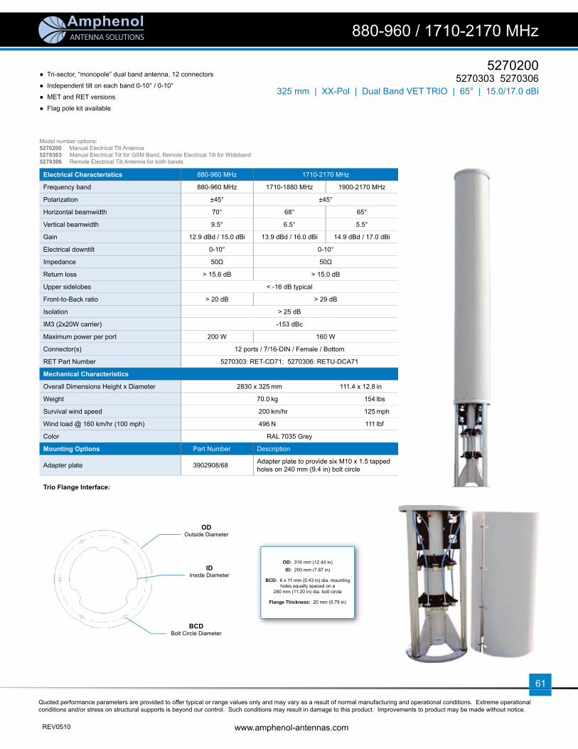
ANTENNA SOLUTIONS
Quoted performance parameters are provided to offer typical or range values only and may vary as a result of normal manufacturing and operational conditions. Extreme operational conditions and/or stress on structural supports is beyond our control. Such conditions may result in damage to this product. Improvements to product may be made without notice.
REV0510 www.amphenol-antennas.com
61
5270200 5270303 5270306
880-960 / 1710-2170 MHz
325 mm | XX-Pol | Dual Band VET TRIO | 65° | 15.0/17.0 dBi
● Tri-sector, “monopole” dual band antenna, 12 connectors
● Independent tilt on each band 0-10° / 0-10°
● MET and RET versions
● Flag pole kit available
Electrical Characteristics 880-960 MHz 1710-2170 MHz
Frequency band 880-960 MHz 1710-1880 MHz 1900-2170 MHz
Polarization ±45° ±45°
Horizontal beamwidth 70° 68° 65°
Vertical beamwidth 9.5° 6.5° 5.5°
Gain 12.9 dBd / 15.0 dBi 13.9 dBd / 16.0 dBi 14.9 dBd / 17.0 dBi
Electrical downtilt 0-10° 0-10°
Impedance 50Ω 50Ω
Return loss > 15.6 dB > 15.0 dB
Upper sidelobes < -16 dB typical
Front-to-Back ratio > 20 dB > 29 dB
Isolation > 25 dB
IM3 (2x20W carrier) -153 dBc
Maximum power per port 200 W 160 W
Connector(s) 12 ports / 7/16-DIN / Female / Bottom
RET Part Number 5270303: RET-CD71; 5270306: RETU-DCA71
Mechanical Characteristics
Overall Dimensions Height x Diameter 2830 x 325 mm 111.4 x 12.8 in
Weight 70.0 kg 154 lbs
Survival wind speed 200 km/hr 125 mph
Wind load @ 160 km/hr (100 mph) 496 N 111 lbf
Color RAL 7035 Grey
Mounting Options Part Number Description
Adapter plate 3902908/68 Adapter plate to provide six M10 x 1.5 tapped holes on 240 mm (9.4 in) bolt circle
Trio Flange Interface:
OD: 316 mm (12.44 in)ID: 200 mm (7.87 in)
BCD: 6 x 11 mm (0.43 in) dia. mounting holes equally spaced on a
280 mm (11.20 in) dia. bolt circle
Flange Thickness: 20 mm (0.79 in)
Model number options:5270200 Manual Electrical Tilt Antenna5270303 Manual Electrical Tilt for GSM Band, Remote Electrical Tilt for Wideband5270306 Remote Electrical Tilt Antenna for both bands
ODOutside Diameter
IDInside Diameter
BCDBolt Circle Diameter

ANTENNA SOLUTIONS
Quoted performance parameters are provided to offer typical or range values only and may vary as a result of normal manufacturing and operational conditions. Extreme operational conditions and/or stress on structural supports is beyond our control. Such conditions may result in damage to this product. Improvements to product may be made without notice.
www.amphenol-antennas.com REV0510
62
52702005270303 5270306
880-960 / 1710-2170 MHz
325 mm | XX-Pol | Dual Band VET TRIO | 65° | 15.0/17.0 dBi
880-960 MHz
Horizontal 0° | Vertical 2° | Vertical 4° | Vertical 6° | Vertical
8° | Vertical 10° | Vertical
1710-2170 MHz
Horizontal 0° | Vertical 2° | Vertical 4° | Vertical 6° | Vertical
8° | Vertical 10° | Vertical
30 25 20 15 51035
-90
-60-120
-150 -30
180 0
150
120
90
60
30
30 25 20 15 51035
-90
-60-120
-150 -30
180 0
150
120
90
60
30
30 25 20 15 51035
-90
-60-120
-150 -30
180 0
150
120
90
60
30
30 25 20 15 51035
-90
-60-120
-150 -30
180 0
150
120
90
60
30
30 25 20 15 51035
-90
-60-120
-150 -30
180 0
150
120
90
60
30
30 25 20 15 51035
-90
-60-120
-150 -30
180 0
150
120
90
60
30
30 25 20 15 51035
-90
-60-120
-150 -30
180 0
150
120
90
60
30
30 25 20 15 51035
-90
-60-120
-150 -30
180 0
150
120
90
60
30
30 25 20 15 51035
-90
-60-120
-150 -30
180 0
150
120
90
60
30
30 25 20 15 51035
-90
-60-120
-150 -30
180 0
150
120
90
60
30
30 25 20 15 51035
-90
-60-120
-150 -30
180 0
150
120
90
60
30
30 25 20 15 51035
-90
-60-120
-150 -30
180 0
150
120
90
60
30
30 25 20 15 51035
-90
-60-120
-150 -30
180 0
150
120
90
60
30
30 25 20 15 51035
-90
-60-120
-150 -30
180 0
150
120
90
60
30

ANTENNA SOLUTIONS
Quoted performance parameters are provided to offer typical or range values only and may vary as a result of normal manufacturing and operational conditions. Extreme operational conditions and/or stress on structural supports is beyond our control. Such conditions may result in damage to this product. Improvements to product may be made without notice.
REV0510 www.amphenol-antennas.com
63
5270400 5270403 5270406
880-960 / 1710-2170 MHz
325 mm | XX-Pol | Dual Band VET TRIO | 65° | 15.0/17.0 dBi
● Flag Tri-sector, “monopole” dual band antenna, 12 connectors
● Independent tilt on each band 0-10° / 0-10°
● MET and RET versions
● Flag pole kit included
Electrical Characteristics 880-960 MHz 1710-2170 MHz
Frequency band 880-960 MHz 1710-1880 MHz 1900-2170 MHz
Polarization ±45° ±45°
Horizontal beamwidth 70° 68° 65°
Vertical beamwidth 9.5° 6.5° 5.5°
Gain 12.9 dBd / 15.0 dBi 13.9 dBd / 16.0 dBi 14.9 dBd / 17.0 dBi
Electrical downtilt 0-10° 0-10°
Impedance 50Ω 50Ω
Return loss > 15.6 dB > 15.0 dB
Upper sidelobes < -16 dB typical
Front-to-Back ratio > 20 dB > 29 dB
Isolation > 25 dB
IM3 (2x20W carrier) < -153 dBc
Maximum power per port 200 W 160 W
Connector(s) 12 ports / 7/16-DIN / Female / Bottom
RET Part Number 5270403: RET-CD71; 5270406: RETU-DCA71
Mechanical Characteristics
Height (with Finial) x Diameter 3120 x 325 mm 122.8 x 12.8 in
Weight 85 kg 187 lbs
Wind load @ 160 km/hr (100 mph)for Tri-Sector + maximum fl ag size 1800 N 405 lbf
Color RAL 7035 Grey
Mounting Options Part Number Description
Adapter plate 3902908/68 Adapter plate to provide six M10 x 1.5 tapped holes on 240 mm (9.4 in) bolt circle
Trio Flange Interface:
Model number reference:5270400 Manual Electrical Tilt Antenna5270403 Manual Electrical Tilt for GSM Band, Remote Electrical Tilt for Wideband5270406 Remote Electrical Tilt Antenna for both bands
OD: 316 mm (12.44 in)ID: 200 mm (7.87 in)
BCD: 6 x 11 mm (0.43 in) dia. mounting holes equally spaced on a
280 mm (11.20 in) dia. bolt circle
Flange Thickness: 20 mm (0.79 in)
ODOutside Diameter
IDInside Diameter
BCDBolt Circle Diameter

ANTENNA SOLUTIONS
Quoted performance parameters are provided to offer typical or range values only and may vary as a result of normal manufacturing and operational conditions. Extreme operational conditions and/or stress on structural supports is beyond our control. Such conditions may result in damage to this product. Improvements to product may be made without notice.
www.amphenol-antennas.com REV0510
64
52704005270403 5270406
880-960 / 1710-2170 MHz
325 mm | XX-Pol | Dual Band VET TRIO | 65° | 15.0/17.0 dBi
880-960 MHz
Horizontal 0° | Vertical 2° | Vertical 4° | Vertical 6° | Vertical
8° | Vertical 10° | Vertical
1710-2170 MHz
Horizontal 0° | Vertical 2° | Vertical 4° | Vertical 6° | Vertical
8° | Vertical 10° | Vertical
30 25 20 15 51035
-90
-60-120
-150 -30
180 0
150
120
90
60
30
30 25 20 15 51035
-90
-60-120
-150 -30
180 0
150
120
90
60
30
30 25 20 15 51035
-90
-60-120
-150 -30
180 0
150
120
90
60
30
30 25 20 15 51035
-90
-60-120
-150 -30
180 0
150
120
90
60
30
30 25 20 15 51035
-90
-60-120
-150 -30
180 0
150
120
90
60
30
30 25 20 15 51035
-90
-60-120
-150 -30
180 0
150
120
90
60
30
30 25 20 15 51035
-90
-60-120
-150 -30
180 0
150
120
90
60
30
30 25 20 15 51035
-90
-60-120
-150 -30
180 0
150
120
90
60
30
30 25 20 15 51035
-90
-60-120
-150 -30
180 0
150
120
90
60
30
30 25 20 15 51035
-90
-60-120
-150 -30
180 0
150
120
90
60
30
30 25 20 15 51035
-90
-60-120
-150 -30
180 0
150
120
90
60
30
30 25 20 15 51035
-90
-60-120
-150 -30
180 0
150
120
90
60
30
30 25 20 15 51035
-90
-60-120
-150 -30
180 0
150
120
90
60
30
30 25 20 15 51035
-90
-60-120
-150 -30
180 0
150
120
90
60
30

ANTENNA SOLUTIONS
Quoted performance parameters are provided to offer typical or range values only and may vary as a result of normal manufacturing and operational conditions. Extreme operational conditions and/or stress on structural supports is beyond our control. Such conditions may result in damage to this product. Improvements to product may be made without notice.
REV0510 www.amphenol-antennas.com
65
5177703 5177603 5177603G
1710-2170 / 1710-2170 MHz
388 mm | XX-Pol | Twin Wideband VET TRIO | 65° | 17.5 dBi
Electrical Characteristics
Frequency band 1710-2170 MHz
Polarization ±45°
Horizontal beamwidth 65° (-3 dB)
Vertical beamwidth 7° (-3 dB)
Gain 15.4 dBd / 17.5 dBi
Electrical downtilt 2-14°
Impedance 50Ω
VSWR < 1.4:1
Upper sidelobe rejection (20° sector above main beam) > 18 dB typical
Null fi ll (fi rst null below main beam) < 18 dB typical
Isolation between ports > 30 dB
Front-to-Back ratio > 25 dB
Isolation between arrays in the same sector > 32 dB
IM3 (2x20W carrier) < -153 dBc
Maximum power per port 160 W
Connector(s) 12 ports / 7/16-DIN / Female, Long Neck / Bottom
RET Part Number (one unit per sector) RETU-DCA21 for AISG1.1 protocol (3 units included in 5177603) RETU-DCG21 for 3GPP/AISG2.0 protocol (3 units included in 5177603G)
Environmental
Operating temperature -40 to +60° C -40 to +140° F
Environmental ETS 300 019
RoHS compliant Yes
Mechanical Characteristics
Total Height (includes 250 mm service area) 1710 mm 67.3 in
Effective Height x Diameter 1335 x 388 mm 52.6 x 15.3 in
Weight 53 kg 116.8 lbs
Survival wind speed 200 km/hr 125 mph
Operational wind speed 160 km/hr 99 mph
Wind load @ 160 km/hr (100 mph) 402 N 90.4 lbf
Shroud Outdoor plastic, RAL 7035 Grey
Relative directions of internal antennas (sector axis) 0° 120° 240°
Packaging
Packing dimensions 1880 x 600 x 530 mm 74 x 23.6 x 20.9 in
Packing weight 105 kg 231.5 lbs
Packing volume 0.60 m3 21.2 ft3
Accessories Part Number Description
Lightning protection kit TRX-LPK Lightning fi nial
Trio extension TRX380-E085-001TRX380-E085-002*
Mounting Mast, 85 cm high x 388 mm diaMounting Mast, 85 cm high x 388 mm dia
*shroud stops 20 cm above bottom fl ange for cables out on the side
Trio-Pack (delivered w/non-penetrating platform) Please contact us
● Tri-sector Twin Wideband antenna, 4 connectors per sector● Two independent arrays per sector● Variable electrical tilt 2-14°● Very small diameter (388 mm) for low wind load● MET and RET versions, AISG1.1 or 3GPP/AISG2.0● Dual-sector & Single-sector antennas available
Model number reference:Tri-sector Dual-sector Single-sector 5177703 5177702 5177701 Manual Electrical Tilt Antenna5177603 5177602 5177601 Remote Electrical Tilt Antenna, AISG1.15177603G 5177602G 5177601G Remote Electrical Tilt Antenna, 3GPP/AISG2.0
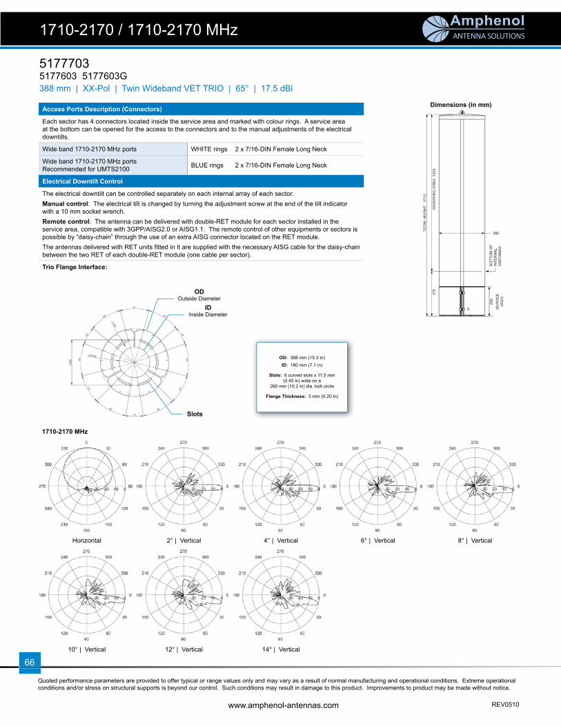
ANTENNA SOLUTIONS
Quoted performance parameters are provided to offer typical or range values only and may vary as a result of normal manufacturing and operational conditions. Extreme operational conditions and/or stress on structural supports is beyond our control. Such conditions may result in damage to this product. Improvements to product may be made without notice.
www.amphenol-antennas.com REV0510
66
Dimensions (in mm)
1710-2170 MHz
Horizontal 2° | Vertical 4° | Vertical 6° | Vertical 8° | Vertical
10° | Vertical 12° | Vertical 14° | Vertical
51777035177603 5177603G
1710-2170 / 1710-2170 MHz
388 mm | XX-Pol | Twin Wideband VET TRIO | 65° | 17.5 dBi
OD: 388 mm (15.3 in)ID: 180 mm (7.1 in)
Slots: 6 curved slots x 11.5 mm (0.45 in) wide on a
260 mm (10.2 in) dia. bolt circle
Flange Thickness: 5 mm (0.20 in)
Access Ports Description (Connectors)
Each sector has 4 connectors located inside the service area and marked with colour rings. A service area at the bottom can be opened for the access to the connectors and to the manual adjustments of the electrical downtilts.
Wide band 1710-2170 MHz ports WHITE rings 2 x 7/16-DIN Female Long Neck
Wide band 1710-2170 MHz portsRecommended for UMTS2100 BLUE rings 2 x 7/16-DIN Female Long Neck
Electrical Downtilt Control
The electrical downtilt can be controlled separately on each internal array of each sector. Manual control: The electrical tilt is changed by turning the adjustment screw at the end of the tilt indicator with a 10 mm socket wrench.Remote control: The antenna can be delivered with double-RET module for each sector installed in the service area, compatible with 3GPP/AISG2.0 or AISG1.1. The remote control of other equipments or sectors is possible by “daisy-chain” through the use of an extra AISG connector located on the RET module.The antennas delivered with RET units fi tted in it are supplied with the necessary AISG cable for the daisy-chain between the two RET of each double-RET module (one cable per sector).
Trio Flange Interface:
ODOutside Diameter
IDInside Diameter
Slots

ANTENNA SOLUTIONS
Quoted performance parameters are provided to offer typical or range values only and may vary as a result of normal manufacturing and operational conditions. Extreme operational conditions and/or stress on structural supports is beyond our control. Such conditions may result in damage to this product. Improvements to product may be made without notice.
REV0510 www.amphenol-antennas.com
67
5863903 5863803 5863803G
880-960 / 1710-2170 MHz
388 mm | XX-Pol | Dual Band VET TRIO | 65° | 16.5/18.0 dBi
Electrical Characteristics 880-960 MHz 1710-2170 MHz
Frequency band 880-960 MHz 1710-1880 MHz 1900-2170 MHz
Polarization ±45° ±45°
Horizontal beamwidth (-3 dB) 65° 65° 64°
Vertical beamwidth (-3 dB) 9° 6° 6°
Gain tilt 0° tilt 5° tilt 10°
16.0...16.5 dBi16.0...16.5 dBi15.9...16.4 dBi
17.3...17.6 dBi17.2...17.4 dBi17.2...17.3 dBi
17.6...18.1 dBi17.4...17.9 dBi17.3...17.7 dBi
Electrical downtilt 0-10° 0-10°
Impedance 50Ω 50Ω
VSWR < 1.4:1 < 1.4:1
Upper sidelobe rejection (20° sector above main beam) 18 dB typical 18 dB typical
Isolation between ports > 30 dB > 30 dB
Isolation between bands 45 dB typical 45 dB typical
Front-to-Back ratio > 30 dB > 30 dB
IM3 (2x20W carrier) < -110 dBm < -110 dBm
Maximum power per port 200 W 160 W
Connector(s) 12 ports / 7/16-DIN / Female, Long Neck / Bottom
RET Part Number (one unit per sector) MDCU-A0001 for AISG1.1 protocol (3 units included in 5863803) MDCU-G0001 for 3GPP/AISG2.0 protocol (3 units included in 5863803G)
We can provide a RET module with separate control of the motors to allow dual-operators or dual-technology control. Please contact us.
Environmental
Operating temperature -40 to +60° C -40 to +140° F
Environmental ETS 300 019
RoHS compliant Yes
Mechanical Characteristics
Total Height (includes 250 mm service area) 2291 mm 90.2 in
Effective Height x Diameter 1900 x 388 mm 74.8 x 15.3 in
Weight 68 kg 149.9 lbs
Survival wind speed 200 km/hr 125 mph
Operational wind speed 160 km/hr 99 mph
Wind load @ 160 km/hr (100 mph) 428 N 96.2 lbf
Shroud Outdoor plastic, RAL 7035 Grey
Relative directions of internal antennas (sector axis) 0° (±15°) 120° (±15°) 240° (±15°)
Packaging
Packing dimensions 2480 x 530 x 600 mm 97.6 x 20.9 x 23.6 in
Packing weight 140 kg 308.6 lbs
Packing volume 0.789 m3 27.9 ft3
Accessories Part Number Description
Lightning protection kit TRX-LPK Lightning fi nial
Trio extension TRX380-E085-001TRX380-E085-002*
Mounting Mast, 85 cm high x 388 mm diaMounting Mast, 85 cm high x 388 mm dia
*shroud stops 20 cm above bottom fl ange for cables out on the side
Trio-Pack (delivered w/non-penetrating platform) Please contact us
● Tri-sector Dual Band antenna, 4 connectors per sector● Independent tilt on each band 0-10° / 0-10°● Independent azimuth panning ±15° on each sector ● Very small diameter (388 mm) for low wind load● MET and RET versions, AISG1.1 or 3GPP/AISG2.0● Dual-sector & Single-sector antennas available
Model number reference:Tri-sector Dual-sector Single-sector 5863903 5863902 5863901 Manual Electrical Tilt Antenna5863803 5863802 5863801 Remote Electrical Tilt Antenna, AISG1.15863803G 5863802G 5863801G Remote Electrical Tilt Antenna, 3GPP/AISG2.0
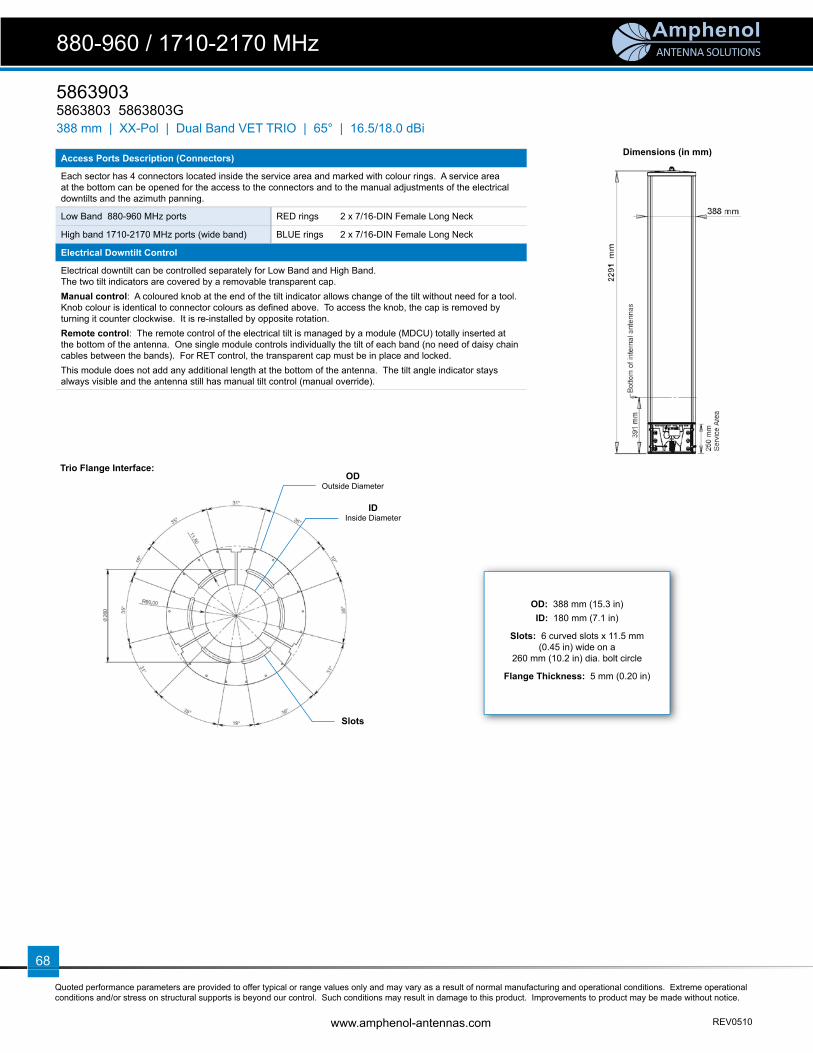
ANTENNA SOLUTIONS
Quoted performance parameters are provided to offer typical or range values only and may vary as a result of normal manufacturing and operational conditions. Extreme operational conditions and/or stress on structural supports is beyond our control. Such conditions may result in damage to this product. Improvements to product may be made without notice.
www.amphenol-antennas.com REV0510
68
58639035863803 5863803G
880-960 / 1710-2170 MHz
388 mm | XX-Pol | Dual Band VET TRIO | 65° | 16.5/18.0 dBi
Dimensions (in mm)
Trio Flange Interface:
OD: 388 mm (15.3 in)ID: 180 mm (7.1 in)
Slots: 6 curved slots x 11.5 mm (0.45 in) wide on a
260 mm (10.2 in) dia. bolt circle
Flange Thickness: 5 mm (0.20 in)
Access Ports Description (Connectors)
Each sector has 4 connectors located inside the service area and marked with colour rings. A service area at the bottom can be opened for the access to the connectors and to the manual adjustments of the electrical downtilts and the azimuth panning.
Low Band 880-960 MHz ports RED rings 2 x 7/16-DIN Female Long Neck
High band 1710-2170 MHz ports (wide band) BLUE rings 2 x 7/16-DIN Female Long Neck
Electrical Downtilt Control
Electrical downtilt can be controlled separately for Low Band and High Band.The two tilt indicators are covered by a removable transparent cap.Manual control: A coloured knob at the end of the tilt indicator allows change of the tilt without need for a tool. Knob colour is identical to connector colours as defi ned above. To access the knob, the cap is removed by turning it counter clockwise. It is re-installed by opposite rotation.Remote control: The remote control of the electrical tilt is managed by a module (MDCU) totally inserted at the bottom of the antenna. One single module controls individually the tilt of each band (no need of daisy chain cables between the bands). For RET control, the transparent cap must be in place and locked. This module does not add any additional length at the bottom of the antenna. The tilt angle indicator stays always visible and the antenna still has manual tilt control (manual override).
ODOutside Diameter
IDInside Diameter
Slots

ANTENNA SOLUTIONS
Quoted performance parameters are provided to offer typical or range values only and may vary as a result of normal manufacturing and operational conditions. Extreme operational conditions and/or stress on structural supports is beyond our control. Such conditions may result in damage to this product. Improvements to product may be made without notice.
REV0510 www.amphenol-antennas.com
69
880-960 MHz
Horizontal 0° | Vertical 2° | Vertical 4° | Vertical 6° | Vertical
8° | Vertical 10° | Vertical
1710-2170 MHz
Horizontal 0° | Vertical 2° | Vertical 4° | Vertical 6° | Vertical
8° | Vertical 10° | Vertical
880-960 / 1710-2170 MHz
58639035863803 5863803G
388 mm | XX-Pol | Dual Band VET TRIO | 65° | 16.5/18.0 dBi

70
ANTENNA SOLUTIONS

ANTENNA SOLUTIONS
Quoted performance parameters are provided to offer typical or range values only and may vary as a result of normal manufacturing and operational conditions. Extreme operational conditions and/or stress on structural supports is beyond our control. Such conditions may result in damage to this product. Improvements to product may be made without notice.
REV0510 www.amphenol-antennas.com
71
5860903 5860803 5860803G
880-960 / 1710-2170 MHz
388 mm | XX-Pol | Dual Band VET TRIO | 65° | 17.5/18.0 dBi
Electrical Characteristics 880-960 MHz 1710-2170 MHz
Frequency band 880-960 MHz 1710-1880 MHz 1900-2170 MHz
Polarization ±45° ±45°
Horizontal beamwidth (-3 dB) 65° 65° 64°
Vertical beamwidth (-3 dB) 7° 6° 6°
Gain tilt 0° tilt 5° tilt 10°
17.0...17.5 dBi17.0...17.5 dBi16.9...17.4 dBi
17.3...17.6 dBi17.2...17.4 dBi17.2...17.3 dBi
17.6...18.1 dBi17.4...17.9 dBi17.3...17.7 dBi
Electrical downtilt 0-10° 0-10°
Impedance 50Ω 50Ω
VSWR < 1.4:1 < 1.4:1
Upper sidelobe rejection (20° sector above main beam) 18 dB typical 18 dB typical
Isolation between ports > 30 dB > 30 dB
Isolation between bands 45 dB typical 45 dB typical
Front-to-Back ratio > 30 dB > 30 dB
IM3 (2x20W carrier) < -110 dBm < -110 dBm
Maximum power per port 200 W 160 W
Connector(s) 12 ports / 7/16-DIN / Female, Long Neck / Bottom
RET Part Number (one unit per sector) MDCU-A0001 for AISG1.1 protocol (3 units included in 5860803) MDCU-G0001 for 3GPP/AISG2.0 protocol (3 units included in 5860803G)
We can provide a RET module with separate control of the motors to allow dual-operators or dual-technology control. Please contact us.
Environmental
Operating temperature -40 to +60° C -40 to +140° F
Environmental ETS 300 019
RoHS compliant Yes
Mechanical Characteristics
Total Height (includes 250 mm service area) 3069 mm 120.8 in
Effective Height x Diameter 2676 x 388 mm 105.4 x 15.3 in
Weight 80 kg 176.4 lbs
Survival wind speed 200 km/hr 125 mph
Operational wind speed 160 km/hr 99 mph
Wind load @ 160 km/hr (100 mph) 570 N 128.1 lbf
Shroud Outdoor plastic, RAL 7035 Grey
Relative directions of internal antennas (sector axis) 0° (±15°) 120° (±15°) 240° (±15°)
Packaging
Packing dimensions 3250 x 550 x 610 mm 128 x 21.7 x 24 in
Packing weight 192 kg 423.3 lbs
Packing volume 1.09 m3 38.5 ft3
Accessories Part Number Description
Lightning protection kit TRX-LPK Lightning fi nial
Trio extension TRX380-E085-001TRX380-E085-002*
Mounting Mast, 85 cm high x 388 mm diaMounting Mast, 85 cm high x 388 mm dia
*shroud stops 20 cm above bottom fl ange for cables out on the side
Trio-Pack (delivered w/non-penetrating platform) Please contact us
● Tri-sector Dual Band antenna, 4 connectors per sector● Independent tilt on each band 0-10° / 0-10°● Independent azimuth panning ±15° on each sector ● Very small diameter (388 mm) for low wind load and visual impact● MET and RET versions, AISG1.1 or 3GPP/AISG2.0● Dual-sector & Single-sector antennas available
Model number reference:Tri-sector Dual-sector Single-sector 5860903 5860902 5860901 Manual Electrical Tilt Antenna5860803 5860802 5860801 Remote Electrical Tilt Antenna, AISG1.15860803G 5860802G 5860801G Remote Electrical Tilt Antenna, 3GPP/AISG2.0

ANTENNA SOLUTIONS
Quoted performance parameters are provided to offer typical or range values only and may vary as a result of normal manufacturing and operational conditions. Extreme operational conditions and/or stress on structural supports is beyond our control. Such conditions may result in damage to this product. Improvements to product may be made without notice.
www.amphenol-antennas.com REV0510
72
58609035860803 5860803G
880-960 / 1710-2170 MHz
388 mm | XX-Pol | Dual Band VET TRIO | 65° | 17.5/18.0 dBi
Dimensions (in mm)
Trio Flange Interface:
OD: 388 mm (15.3 in)ID: 180 mm (7.1 in)
Slots: 6 curved slots x 11.5 mm (0.45 in) wide on a
260 mm (10.2 in) dia. bolt circle
Flange Thickness: 5 mm (0.20 in)
Access Ports Description (Connectors)
Each sector has 4 connectors located inside the service area and marked with colour rings. A service area at the bottom can be opened for the access to the connectors and to the manual adjustments of the electrical downtilts and the azimuth panning.
Low Band 880-960 MHz ports RED rings 2 x 7/16-DIN Female Long Neck
High band 1710-2170 MHz ports (wide band) BLUE rings 2 x 7/16-DIN Female Long Neck
Electrical Downtilt Control
Electrical downtilt can be controlled separately for Low Band and High Band.The two tilt indicators are covered by a removable transparent cap.Manual control: A coloured knob at the end of the tilt indicator allows change of the tilt without need for a tool. Knob colour is identical to connector colours as defi ned above. To access the knob, the cap is removed by turning it counter clockwise. It is re-installed by opposite rotation.Remote control: The remote control of the electrical tilt is managed by a module (MDCU) totally inserted at the bottom of the antenna. One single module controls individually the tilt of each band (no need of daisy chain cables between the bands). For RET control, the transparent cap must be in place and locked. This module does not add any additional length at the bottom of the antenna. The tilt angle indicator stays always visible and the antenna still has manual tilt control (manual override).
ODOutside Diameter
IDInside Diameter
Slots

ANTENNA SOLUTIONS
Quoted performance parameters are provided to offer typical or range values only and may vary as a result of normal manufacturing and operational conditions. Extreme operational conditions and/or stress on structural supports is beyond our control. Such conditions may result in damage to this product. Improvements to product may be made without notice.
REV0510 www.amphenol-antennas.com
73
880-960 MHz
Horizontal 0° | Vertical 2° | Vertical 4° | Vertical 6° | Vertical
8° | Vertical 10° | Vertical
1710-2170 MHz
Horizontal 0° | Vertical 2° | Vertical 4° | Vertical 6° | Vertical
8° | Vertical 10° | Vertical
880-960 / 1710-2170 MHz
58609035860803 5860803G
388 mm | XX-Pol | Dual Band VET TRIO | 65° | 17.5/18.0 dBi

74
ANTENNA SOLUTIONS

ANTENNA SOLUTIONS
Quoted performance parameters are provided to offer typical or range values only and may vary as a result of normal manufacturing and operational conditions. Extreme operational conditions and/or stress on structural supports is beyond our control. Such conditions may result in damage to this product. Improvements to product may be made without notice.
REV0510 www.amphenol-antennas.com
75
5880903 5880803 5880803G
880-960 / 1710-2170 / 1710-2170 MHz
388 mm | XXX-Pol | Tri Band VET TRIO | 65° | 17.5/17.2/17.3 dBi
Electrical Characteristics 880-960 MHz 1710-2170 MHz 1710-2170 MHzFrequency band 880-960 MHz 1710-1880 MHz 1900-2170 MHz 1710-1880 MHz 1900-2170 MHzPolarization ±45° ±45° ±45°Horizontal beamwidth (-3 dB) 65° 65° 62° 65° 62°Vertical beamwidth (-3 dB) 7° 7° 7° 7° 7°
Gain tilt 0° tilt 5° tilt 10°
17.0...17.5 dBi17.0...17.5 dBi16.9...17.4 dBi
16.5...16.7 dBi16.3...16.5 dBi16.0...16.3 dBi
16.7...17.2 dBi16.5...17.0 dBi16.3...16.5 dBi
16.5...16.9 dBi16.4...16.7 dBi16.3...16.5 dBi
16.9...17.3 dBi16.7...17.2 dBi16.5...17.0 dBi
Electrical downtilt 0-10° 0-12° 0-12°Impedance 50Ω 50Ω 50ΩVSWR < 1.4:1 < 1.4:1 < 1.4:1
Upper sidelobe rejection (20° sector above main beam) 18 dB typical 18 dB typical 18 dB typical
Isolation between ports > 30 dB > 30 dB > 30 dBIsolation between bands 45 dB typical 45 dB typical 45 dB typicalFront-to-Back ratio > 30 dB > 30 dB > 30 dBIM3 (2x20W carrier) < -110 dBm < -110 dBm < -110 dBmMaximum power per port 200 W 160 W 160 WConnector(s) 18 ports / 7/16-DIN / Female, Long Neck / Bottom
RET Part Number (one unit per sector)
MDCU-A0002 for AISG1.1 protocol (3 units included in 5880803) MDCU-G0002 for 3GPP/AISG2.0 protocol (3 units included in 5880803G)
We can provide a RET module with separate control of the motors to allow dual-operators or dual-technology control. Please contact us.
EnvironmentalOperating temperature -40 to +60° C -40 to +140° FEnvironmental ETS 300 019RoHS compliant YesMechanical CharacteristicsTotal Height (includes 250 mm service area) 3069 mm 120.8 inEffective Height x Diameter 2676 x 388 mm 105.4 x 15.3 inWeight 98 kg 216 lbsSurvival wind speed 200 km/hr 125 mphOperational wind speed 160 km/hr 99 mphWind load @ 160 km/hr (100 mph) 570 N 128.1 lbfShroud Outdoor plastic, RAL 7035 Grey
Relative directions of internal antennas (sector axis) 0° (±15°) 120° (±15°) 240° (±15°)
PackagingPacking dimensions 3250 x 550 x 610 mm 128 x 21.7 x 24 inPacking weight 210 kg 463 lbsPacking volume 1.09 m3 38.5 ft3
Accessories Part Number DescriptionLightning protection kit TRX-LPK Lightning fi nial
Trio extension TRX380-E085-001TRX380-E085-002*
Mounting Mast, 85 cm high x 388 mm diaMounting Mast, 85 cm high x 388 mm dia
*shroud stops 20 cm above bottom fl ange for cables out on the side
Trio-Pack (delivered w/non-penetrating platform) Please contact us
● Tri-sector Tri Band antenna, 6 connectors per sector● Independent tilt on each band 0-10° / 0-12° / 0-12° ● Independent azimuth panning ±15° on each sector● Very small diameter (388 mm) for low wind load● MET and RET versions, AISG1.1 or 3GPP/AISG2.0● Dual-sector & Single-sector antennas available
Model number reference:Tri-sector Dual-sector Single-sector 5880903 5880902 5880901 Manual Electrical Tilt Antenna5880803 5880802 5880801 Remote Electrical Tilt Antenna, AISG1.15880803G 5880802G 5880801G Remote Electrical Tilt Antenna, 3GPP/AISG2.0

ANTENNA SOLUTIONS
Quoted performance parameters are provided to offer typical or range values only and may vary as a result of normal manufacturing and operational conditions. Extreme operational conditions and/or stress on structural supports is beyond our control. Such conditions may result in damage to this product. Improvements to product may be made without notice.
www.amphenol-antennas.com REV0510
76
58809035880803 5880803G
880-960 / 1710-2170 / 1710-2170 MHz
388 mm | XXX-Pol | Tri Band VET TRIO | 65° | 17.5/17.2/17.3 dBi
Dimensions
Trio Flange Interface:
OD: 388 mm (15.3 in)ID: 180 mm (7.1 in)
Slots: 6 curved slots x 11.5 mm (0.45 in) wide on a
260 mm (10.2 in) dia. bolt circle
Flange Thickness: 5 mm (0.20 in)
Access Ports Description (Connectors)
Each sector has 6 connectors located inside the service area and marked with colour rings. A service area at the bottom can be opened for the access to the connectors and to the manual adjustments of the electrical downtilts and the azimuth panning.
Low Band 880-960 MHz ports RED rings 2 x 7/16-DIN Female Long Neck
High band 1710-2170 MHz ports (top array)pattern optimised for DCS1800 WHITE rings 2 x 7/16-DIN Female Ultra Long Neck
High band 1710-2170 MHz ports (bottom array)pattern optimised for UMTS2100 BLUE rings 2 x 7/16-DIN Female Long Neck
Electrical Downtilt Control
Electrical downtilt can be controlled separately for Low Band, High Band White and High Band Blue.The three tilt indicators are covered by a removable transparent cap.Manual control: A coloured knob at the end of the tilt indicator allows change of the tilt without need for a tool. Knob colour is identical to connector colours as defi ned above. To access the knob, the cap is removed by turning it counter clockwise. It is re-installed by opposite rotation.Remote control: The remote control of the electrical tilt is managed by a module (MDCU) totally inserted at the bottom of the antenna. One single module controls individually the tilt of each band (no need of daisy chain cables between the bands). For RET control, the transparent cap must be in place and locked. This module does not add any additional length at the bottom of the antenna. The tilt angle indicator stays always visible and the antenna still has manual tilt control (manual override).
ODOutside Diameter
IDInside Diameter
Slots

ANTENNA SOLUTIONS
Quoted performance parameters are provided to offer typical or range values only and may vary as a result of normal manufacturing and operational conditions. Extreme operational conditions and/or stress on structural supports is beyond our control. Such conditions may result in damage to this product. Improvements to product may be made without notice.
REV0510 www.amphenol-antennas.com
77
880-960 MHz
Horizontal 0° | Vertical 2° | Vertical 4° | Vertical 6° | Vertical
8° | Vertical 10° | Vertical
1710-2170 MHz (top array)
Horizontal 0° | Vertical 2° | Vertical 4° | Vertical 6° | Vertical
8° | Vertical 10° | Vertical 12° | Vertical
880-960 / 1710-2170 / 1710-2170 MHz
58809035880803 5880803G
388 mm | XXX-Pol | Tri Band VET TRIO | 65° | 17.5/17.2/17.3 dBi

ANTENNA SOLUTIONS
Quoted performance parameters are provided to offer typical or range values only and may vary as a result of normal manufacturing and operational conditions. Extreme operational conditions and/or stress on structural supports is beyond our control. Such conditions may result in damage to this product. Improvements to product may be made without notice.
www.amphenol-antennas.com REV0510
78
58809035880803 5880803G
880-960 / 1710-2170 / 1710-2170 MHz
388 mm | XXX-Pol | Tri Band VET TRIO | 65° | 17.5/17.2/17.3 dBi
1710-2170 MHz (bottom array)
Horizontal 0° | Vertical 2° | Vertical 4° | Vertical 6° | Vertical
8° | Vertical 10° | Vertical 12° | Vertical
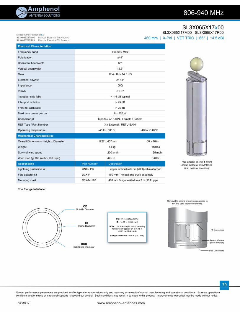
ANTENNA SOLUTIONS
Quoted performance parameters are provided to offer typical or range values only and may vary as a result of normal manufacturing and operational conditions. Extreme operational conditions and/or stress on structural supports is beyond our control. Such conditions may result in damage to this product. Improvements to product may be made without notice.
REV0510 www.amphenol-antennas.com
79
SL3X065X17x00SL3X065X17M00 SL3X065X17R00
806-940 MHz
460 mm | X-Pol | VET TRIO | 65° | 14.5 dBiModel number options (x):SL3X065X17M00 Manual Electrical Tilt AntennaSL3X065X17R00 Remote Electrical Tilt Antenna
Electrical Characteristics
Frequency band 806-940 MHz
Polarization ±45°
Horizontal beamwidth 65°
Vertical beamwidth 14.5°
Gain 12.4 dBd / 14.5 dBi
Electrical downtilt 2°-14°
Impedance 50Ω
VSWR < 1.5:1
1st upper side lobe < -16 dB typical
Inter-port isolation > 25 dB
Front-to-Back ratio > 25 dB
Maximum power per port 6 x 500 W
Connector(s) 6 ports / 7/16-DIN / Female / Bottom
RET Type / Part Number 3 x External / RETU-EA01
Operating temperature -40 to +60° C -40 to +140° F
Mechanical Characteristics
Overall Dimensions Height x Diameter 1727 x 457 mm 68 x 18 in
Weight 51 kg 113 lbs
Survival wind speed 200 km/hr 125 mph
Wind load @ 160 km/hr (100 mph) 425 N 96 lbf
Accessories Part Number Description
Lightning protection kit UNX-LPK Copper air fi nial with 6m (20 ft) cable attached
Flag adapter kit D3X-F 460 mm Trio ball and truck assembly
Mounting mast D3X-M-120 460 mm fl ange welded to a 3 m (10 ft) pipe
Trio Flange Interface:
OD: 17.75 in (450.9 mm)ID: 14.00 in (355.6 mm)
BCD: 12 x 0.56 dia (14.2 mm) mounting holes equally spaced on a 15.75 in
(400.1 mm) bolt circle
Flange Thickness: 0.50 in (12.7 mm)
RF Connectors
Access Window (panel removed)
Data Connectors
Removable panels provide easy access to RF and data cable connections.
Flag adapter kit (ball & truck) shown on top of Trio Antenna
is an optional accessory
ODOutside Diameter
IDInside Diameter
BCDBolt Circle Diameter
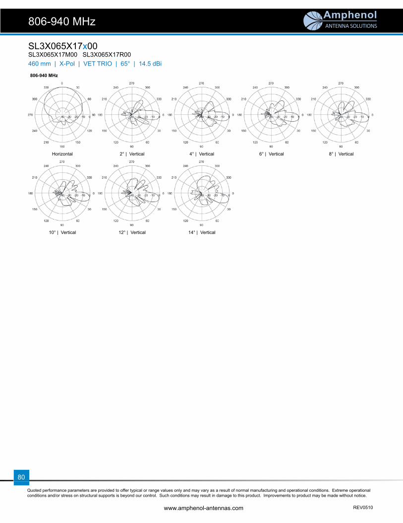
ANTENNA SOLUTIONS
Quoted performance parameters are provided to offer typical or range values only and may vary as a result of normal manufacturing and operational conditions. Extreme operational conditions and/or stress on structural supports is beyond our control. Such conditions may result in damage to this product. Improvements to product may be made without notice.
www.amphenol-antennas.com REV0510
80
SL3X065X17x00SL3X065X17M00 SL3X065X17R00
806-940 MHz
460 mm | X-Pol | VET TRIO | 65° | 14.5 dBi
806-940 MHz
Horizontal 2° | Vertical 4° | Vertical 6° | Vertical 8° | Vertical
10° | Vertical 12° | Vertical 14° | Vertical

ANTENNA SOLUTIONS
Quoted performance parameters are provided to offer typical or range values only and may vary as a result of normal manufacturing and operational conditions. Extreme operational conditions and/or stress on structural supports is beyond our control. Such conditions may result in damage to this product. Improvements to product may be made without notice.
REV0510 www.amphenol-antennas.com
81
WB3X065T17x00WB3X065T17M00 WB3X065T17R00
1710-2170 / 1710-2170 MHz
460 mm | XX-Pol | Twin Wideband VET TRIO | 65° | 17.5 dBiModel number options (x):WB3X065T17M00 Manual Electrical Tilt AntennaWB3X065T17R00 Remote Electrical Tilt Antenna
Electrical Characteristics 1710-2170 MHz
Frequency band 1710-1880 MHz 1850-1990 MHz 1900-2170 MHz
Polarization ±45°
Horizontal beamwidth 68° 65° 62°
Vertical beamwidth 6.8° 6.6° 6.2°
Gain 14.4 dBd / 16.5 dBi 14.9 dBd / 17.0 dBi 15.4 dBd / 17.5 dBi
Electrical downtilt 2°-10°
Impedance 50Ω
VSWR < 1.5:1
1st upper side lobe < -18 dB
Inter-port isolation > 30 dB
Front-to-Back ratio > 25 dB
Maximum power per port 12 x 250 W
Connector(s) 12 ports / 7/16-DIN / Female / Bottom
RET Type / Part Number 6 x External / RETU-EA01
Operating temperature -40 to +60° C -40 to +140° F
Mechanical Characteristics
Overall Dimensions Height x Diameter 1727 x 457 mm 68 x 18 in
Weight 64 kg 140 lbs
Survival wind speed 200 km/hr 125 mph
Wind load @ 160 km/hr (100 mph) 425 N 96 lbf
Accessories Part Number Description
Lightning protection kit UNX-LPK Copper air fi nial with 6m (20 ft) cable attached
Flag adapter kit D3X-F 460 mm Trio ball and truck assembly
Mounting mast D3X-M-120 460 mm fl ange welded to a 3 m (10 ft) pipe
Trio Flange Interface:
1800 MHz 1900 MHz 2100 MHz
Horizontal Horizontal Horizontal
OD: 17.75 in (450.9 mm)ID: 14.00 in (355.6 mm)
BCD: 12 x 0.56 dia (14.2 mm) mounting holes equally spaced on a 15.75 in
(400.1 mm) bolt circle
Flange Thickness: 0.50 in (12.7 mm)
ODOutside Diameter
IDInside Diameter
BCDBolt Circle Diameter

ANTENNA SOLUTIONS
Quoted performance parameters are provided to offer typical or range values only and may vary as a result of normal manufacturing and operational conditions. Extreme operational conditions and/or stress on structural supports is beyond our control. Such conditions may result in damage to this product. Improvements to product may be made without notice.
www.amphenol-antennas.com REV0510
82
WB3X065T17x00WB3X065T17M00 WB3X065T17R00
1710-2170 / 1710-2170 MHz
460 mm | XX-Pol | Twin Wideband VET TRIO | 65° | 17.5 dBi
1800 MHz 1900 MHz 2100 MHz
2° | Vertical 2° | Vertical 2° | Vertical
4° | Vertical 4° | Vertical 4° | Vertical
6° | Vertical 6° | Vertical 6° | Vertical
8° | Vertical 8° | Vertical 8° | Vertical
10° | Vertical 10° | Vertical 10° | Vertical

ANTENNA SOLUTIONS
Quoted performance parameters are provided to offer typical or range values only and may vary as a result of normal manufacturing and operational conditions. Extreme operational conditions and/or stress on structural supports is beyond our control. Such conditions may result in damage to this product. Improvements to product may be made without notice.
REV0510 www.amphenol-antennas.com
83
DS3X065X17x10DS3X065X17M10 DS3X065X17R10
806-940 / 1710-2170 MHz
460 mm | XX-Pol | Dual Band VET TRIO w/Diplexer | 65° | 14.0/17.0 dBiModel number options (x):DS3X065X17M10 Manual Electrical Tilt AntennaDS3X065X17R10 Remote Electrical Tilt Antenna
Electrical Characteristics 806-940 MHz 1710-2170 MHz
Frequency band 806-940 MHz 1710-1880 MHz 1850-1990 MHz 1900-2170 MHz
Polarization ±45° ±45°
Horizontal beamwidth 65° 65° 63° 60°
Vertical beamwidth 14.5° 6.8° 6.6° 6.2°
Gain 11.9 dBd / 14.0 dBi 13.9 dBd / 16.0 dBi 14.4 dBd / 16.5 dBi 14.9 dBd / 17.0 dBi
Electrical downtilt 2°-14° 2°-10°
Impedance 50Ω 50Ω
VSWR < 1.5:1 < 1.5:1
1st upper side lobe < -16 dB typical < -18 dB typical
Inter-port isolation > 25 dB > 30 dB
Inter-band isolation > 25 dB > 30 dB
Front-to-Back ratio > 25 dB > 25 dB
Maximum power per port 6 x 500 W 6 x 250 W
Connector(s) 6 ports / 7/16-DIN / Female / Bottom
RET Type / Part Number 6 x External / RETU-EA01
Operating temperature -40 to +60° C -40 to +140° F
Mechanical Characteristics
Overall Dimensions Height x Diameter 1727 x 457 mm 68 x 18 in
Weight 64 kg 140 lbs
Survival wind speed 200 km/hr 125 mph
Wind load @ 160 km/hr (100 mph) 425 N 96 lbf
Accessories Part Number Description
Lightning protection kit UNX-LPK Copper air fi nial with 6m (20 ft) cable attached
Flag adapter kit D3X-F 460 mm Trio ball and truck assembly
Mounting mast D3X-M-120 460 mm fl ange welded to a 3 m (10 ft) pipe
Trio Flange Interface:
OD: 17.75 in (450.9 mm)ID: 14.00 in (355.6 mm)
BCD: 12 x 0.56 dia (14.2 mm) mounting holes equally spaced on a 15.75 in
(400.1 mm) bolt circle
Flange Thickness: 0.50 in (12.7 mm)
RF Connectors
Access Window (panel removed)
Data Connectors
Removable panels provide easy access to RF and data cable connections.
Flag adapter kit (ball & truck) shown on top of Trio Antenna
is an optional accessory
ODOutside Diameter
IDInside Diameter
BCDBolt Circle Diameter

ANTENNA SOLUTIONS
Quoted performance parameters are provided to offer typical or range values only and may vary as a result of normal manufacturing and operational conditions. Extreme operational conditions and/or stress on structural supports is beyond our control. Such conditions may result in damage to this product. Improvements to product may be made without notice.
www.amphenol-antennas.com REV0510
84
DS3X065X17x10DS3X065X17M10 DS3X065X17R10
806-940 / 1710-2170 MHz
460 mm | XX-Pol | Dual Band VET TRIO w/Diplexer | 65° | 14.0/17.0 dBi
806-940 MHz
Horizontal 2° | Vertical 4° | Vertical 6° | Vertical 8° | Vertical
10° | Vertical 12° | Vertical 14° | Vertical
1710-2170 MHz
Horizontal 2° | Vertical 4° | Vertical 6° | Vertical 8° | Vertical
10° | Vertical

ANTENNA SOLUTIONS
Quoted performance parameters are provided to offer typical or range values only and may vary as a result of normal manufacturing and operational conditions. Extreme operational conditions and/or stress on structural supports is beyond our control. Such conditions may result in damage to this product. Improvements to product may be made without notice.
REV0510 www.amphenol-antennas.com
85
DS3X065X17x00DS3X065X17M00 DS3X065X17R00
806-940 / 1710-2170 MHz
460 mm | XX-Pol | Dual Band VET TRIO | 65° | 14.5/17.5 dBiModel number options (x):DS3X065X17M00 Manual Electrical Tilt AntennaDS3X065X17R00 Remote Electrical Tilt Antenna
Electrical Characteristics 806-940 MHz 1710-2170 MHz
Frequency band 806-940 MHz 1710-1880 MHz 1850-1990 MHz 1900-2170 MHz
Polarization ±45° ±45°
Horizontal beamwidth 65° 65° 63° 60°
Vertical beamwidth 14.5° 6.8° 6.6° 6.2°
Gain 12.4 dBd / 14.5 dBi 14.4 dBd / 16.5 dBi 14.9 dBd / 17.0 dBi 15.4 dBd / 17.5 dBi
Electrical downtilt 2°-14° 2°-10°
Impedance 50Ω 50Ω
VSWR < 1.5:1 < 1.5:1
1st upper side lobe < -16 dB typical < -18 dB typical
Inter-port isolation > 25 dB > 30 dB
Inter-band isolation > 25 dB > 30 dB
Front-to-Back ratio > 25 dB > 25 dB
Maximum power per port 6 x 500 W 6 x 250 W
Connector(s) 12 ports / 7/16-DIN / Female / Bottom
RET Type / Part Number 6 x External / RETU-EA01
Operating temperature -40 to +60° C -40 to +140° F
Mechanical Characteristics
Overall Dimensions Height x Diameter 1727 x 457 mm 68 x 18 in
Weight 64 kg 140 lbs
Survival wind speed 200 km/hr 125 mph
Wind load @ 160 km/hr (100 mph) 425 N 96 lbf
Accessories Part Number Description
Lightning protection kit UNX-LPK Copper air fi nial with 6m (20 ft) cable attached
Flag adapter kit D3X-F 460 mm Trio ball and truck assembly
Mounting mast D3X-M-120 460 mm fl ange welded to a 3 m (10 ft) pipe
Trio Flange Interface:
OD: 17.75 in (450.9 mm)ID: 14.00 in (355.6 mm)
BCD: 12 x 0.56 dia (14.2 mm) mounting holes equally spaced on a 15.75 in
(400.1 mm) bolt circle
Flange Thickness: 0.50 in (12.7 mm)
RF Connectors
Access Window (panel removed)
Data Connectors
Removable panels provide easy access to RF and data cable connections.
Flag adapter kit (ball & truck) shown on top of Trio Antenna
is an optional accessory
ODOutside Diameter
IDInside Diameter
BCDBolt Circle Diameter
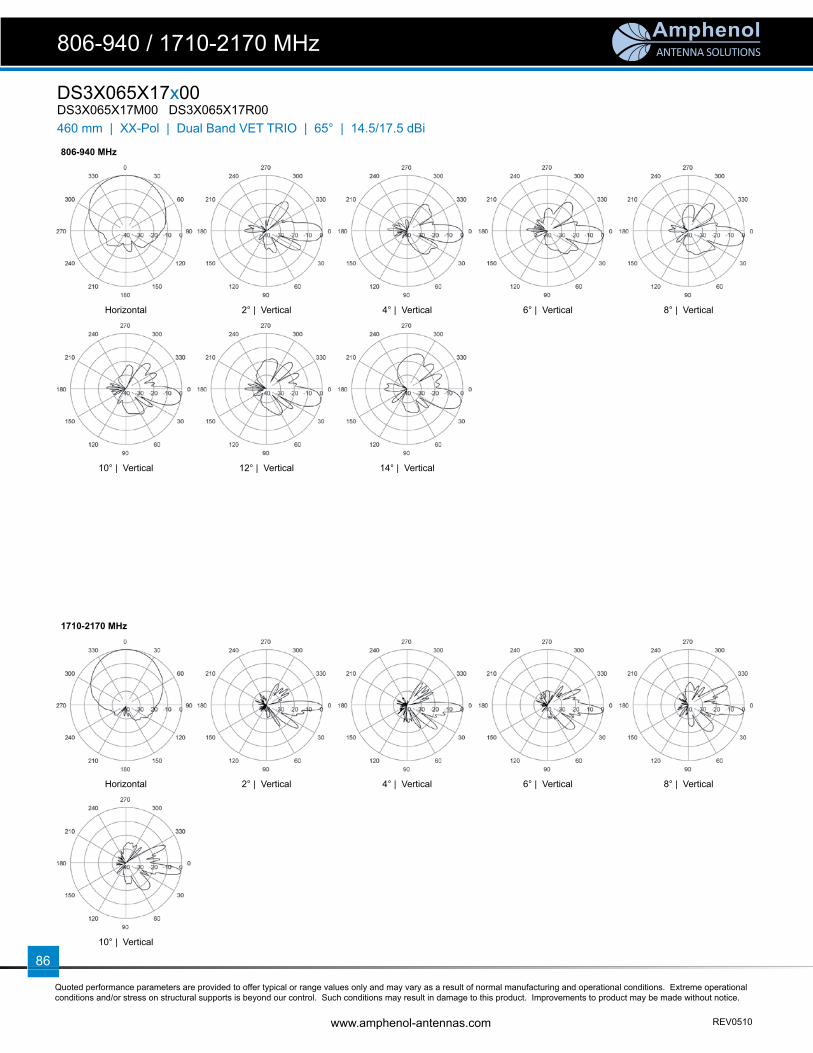
ANTENNA SOLUTIONS
Quoted performance parameters are provided to offer typical or range values only and may vary as a result of normal manufacturing and operational conditions. Extreme operational conditions and/or stress on structural supports is beyond our control. Such conditions may result in damage to this product. Improvements to product may be made without notice.
www.amphenol-antennas.com REV0510
86
DS3X065X17x00DS3X065X17M00 DS3X065X17R00
806-940 / 1710-2170 MHz
460 mm | XX-Pol | Dual Band VET TRIO | 65° | 14.5/17.5 dBi
806-940 MHz
Horizontal 2° | Vertical 4° | Vertical 6° | Vertical 8° | Vertical
10° | Vertical 12° | Vertical 14° | Vertical
1710-2170 MHz
Horizontal 2° | Vertical 4° | Vertical 6° | Vertical 8° | Vertical
10° | Vertical

ANTENNA SOLUTIONS
Quoted performance parameters are provided to offer typical or range values only and may vary as a result of normal manufacturing and operational conditions. Extreme operational conditions and/or stress on structural supports is beyond our control. Such conditions may result in damage to this product. Improvements to product may be made without notice.
REV0510 www.amphenol-antennas.com
87
TW3X065X17x00TW3X065X17M00 TW3X065X17R00
824-960 / 1710-2170 / 1710-2170 MHz
460 mm | XXX-Pol | Tri Band VET TRIO w/Diplexer | 65° | 14.0/17.0/17.0 dBiModel number options (x):TW3X065X17M00 Manual Electrical Tilt AntennaTW3X065X17R00 Remote Electrical Tilt Antenna
Electrical Characteristics 824-960 MHz 1710-2170 MHz
Frequency band 824-896 Mhz 870-960 MHz 1710-1880 MHz 1850-1990 MHz 1900-2170 MHz
Polarization ±45° ±45°
Horizontal beamwidth 65° 65° 63° 60°
Vertical beamwidth 14.5° 14.0° 6.8° 6.6° 6.2°
Gain 11.9 dBd / 14.0 dBi 13.9 dBd / 16.0 dBi 14.4 dBd / 16.5 dBi 14.9 dBd / 17.0 dBi
Electrical downtilt 2°-14° 2°-10°
Impedance 50Ω 50Ω
VSWR < 1.4:1 < 1.5:1 < 1.5:1
1st upper side lobe < -16 dB typical < -18 dB typical < -18 dB typical
In band isolation > 25 dB > 30 dB > 30 dB
Inter-band isolation > 25 dB > 30 dB > 30 dB
Front-to-Back ratio > 25 dB > 25 dB
Maximum power per port 6 x 500 W 12 x 250 W
Connector(s) 12 ports / 7/16-DIN / Female / Bottom
RET Type / Part Number 9 x External / RETU-EA01
Operating temperature -40 to +60° C -40 to +140° F
Mechanical Characteristics
Overall Dimensions Height x Diameter 1727 x 457 mm 68 x 18 in
Weight 69 kg 152 lbs
Survival wind speed 200 km/hr 125 mph
Wind load @ 160 km/hr (100 mph) 425 N 96 lbf
Accessories Part Number Description
Lightning protection kit UNX-LPK Copper air fi nial with 6m (20 ft) cable attached
Flag adapter kit D3X-F 460 mm Trio ball and truck assembly
Mounting mast D3X-M-120 460 mm fl ange welded to a 3 m (10 ft) pipe
Trio Flange Interface:
OD: 17.75 in (450.9 mm)ID: 14.00 in (355.6 mm)
BCD: 12 x 0.56 dia (14.2 mm) mounting holes equally spaced on a 15.75 in
(400.1 mm) bolt circle
Flange Thickness: 0.50 in (12.7 mm)
RF Connectors
Access Window (panel removed)
Data Connectors
Removable panels provide easy access to RF and data cable connections.
ODOutside Diameter
IDInside Diameter
BCDBolt Circle Diameter

ANTENNA SOLUTIONS
Quoted performance parameters are provided to offer typical or range values only and may vary as a result of normal manufacturing and operational conditions. Extreme operational conditions and/or stress on structural supports is beyond our control. Such conditions may result in damage to this product. Improvements to product may be made without notice.
www.amphenol-antennas.com REV0510
88
TW3X065X17x00TW3X065X17M00 TW3X065X17R00
824-960 / 1710-2170 / 1710-2170 MHz
460 mm | XXX-Pol | Tri Band VET TRIO w/Diplexer | 65° | 14.0/17.0/17.0 dBi
806-940 MHz
Horizontal 2° | Vertical 4° | Vertical 6° | Vertical 8° | Vertical
10° | Vertical 12° | Vertical 14° | Vertical
1710-2170 MHz
Horizontal 2° | Vertical 4° | Vertical 6° | Vertical 8° | Vertical
10° | Vertical

w w w . a m p h e n o l - a n t e n n a s . c o m
89
TRIO Accessor ies
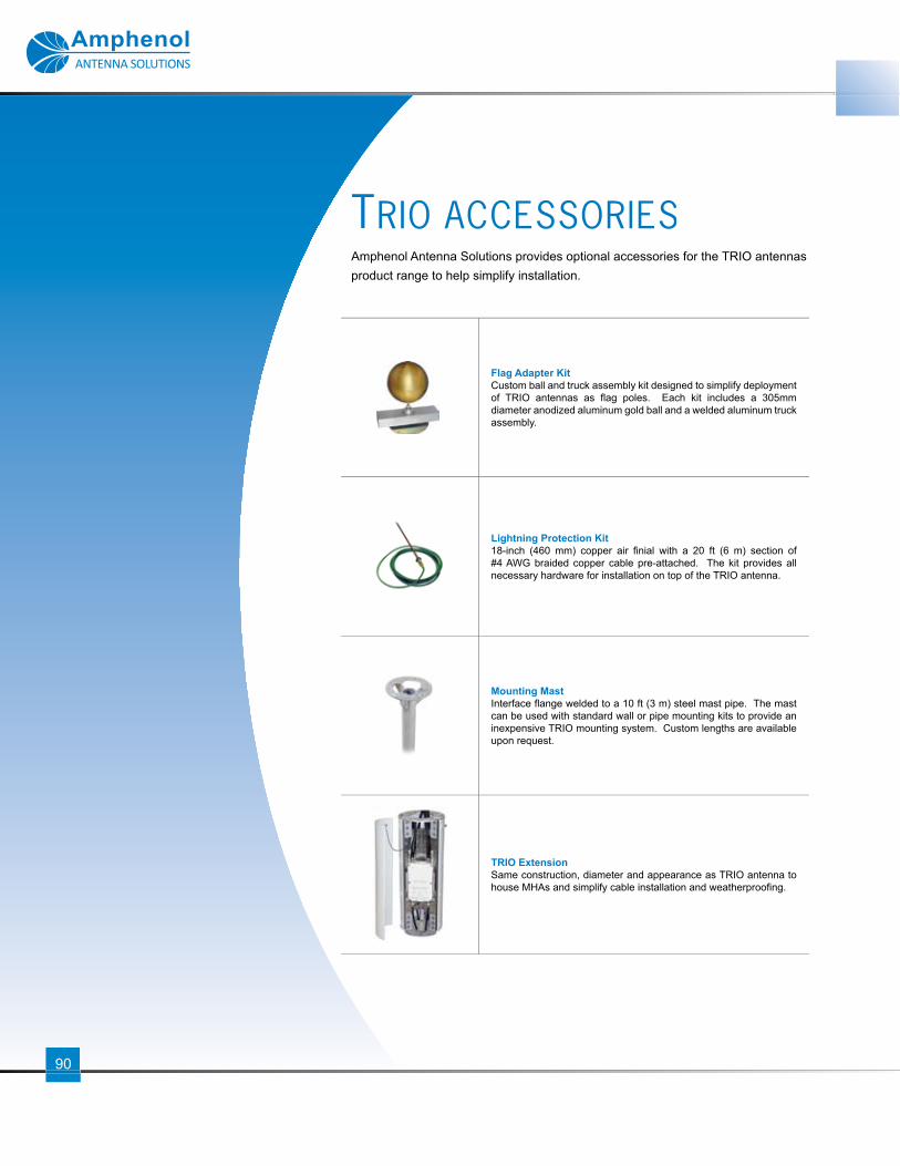
ANTENNA SOLUTIONS
90
Flag Adapter KitCustom ball and truck assembly kit designed to simplify deployment of TRIO antennas as fl ag poles. Each kit includes a 305mm diameter anodized aluminum gold ball and a welded aluminum truck assembly.
Lightning Protection Kit18-inch (460 mm) copper air fi nial with a 20 ft (6 m) section of #4 AWG braided copper cable pre-attached. The kit provides all necessary hardware for installation on top of the TRIO antenna.
Mounting MastInterface fl ange welded to a 10 ft (3 m) steel mast pipe. The mast can be used with standard wall or pipe mounting kits to provide an inexpensive TRIO mounting system. Custom lengths are available upon request.
TRIO ExtensionSame construction, diameter and appearance as TRIO antenna to house MHAs and simplify cable installation and weatherproofi ng.
Amphenol Antenna Solutions provides optional accessories for the TRIO antennas product range to help simplify installation.
TRIO ACCESSORIES

w w w . a m p h e n o l - a n t e n n a s . c o m
91
TRIO Model Numbers
Trio Accessories Part Numbers
Flag Adapter Kit Lightning Protection Kit Mounting Mast TRIO Extension Non-Pentrating
Platform compatible
TRIO
191 WB3X080X06Fx50 -- -- -- -- No
WB3X080X12Fx50 -- -- -- -- No
TRIO
230
GSM3X75-13-A -- integral -- -- Yes
GSM3X75-22-A -- integral -- -- Yes
5162703 -- TRX-LPK -- TRX230-E085-002 Yes
5176703 -- TRX-LPK -- TRX230-E085-002 Yes
5230703 -- TRX-LPK -- TRX230-E085-002 Yes
WB3X072X18x00 W3X-F UNX-LPK W3X-M-120 -- No
WB3X072X24x00 W3X-F UNX-LPK W3X-M-120 -- No
TRIO
280 5066222 -- integral -- -- Yes
5067222 -- integral -- -- Yes
TRIO
310
5176903 -- TRX-LPK -- TRX310-E085-001 TRX310-E085-002 Yes
5230903 -- TRX-LPK -- TRX310-E085-001TRX310-E085-002 Yes
5162903 -- TRX-LPK -- TRX310-E085-001TRX310-E085-002 Yes
5863703 -- TRX-LPK -- TRX310-E085-001TRX310-E085-002 Yes
5880713 -- TRX-LPK -- TRX310-E085-001TRX310-E085-002 Yes
TRIO
325
5270500 -- integral -- -- Yes
5270200 -- integral -- -- Yes
5270400 integral integral -- -- No
TRIO
380
5177703 -- TRX-LPK -- TRX380-E085-001 TRX380-E085-002 Yes
5860903 -- TRX-LPK -- TRX380-E085-001TRX380-E085-002 Yes
5863903 -- TRX-LPK -- TRX380-E085-001TRX380-E085-002 Yes
5880903 -- TRX-LPK -- TRX380-E085-001TRX380-E085-002 Yes
TRIO
460
SL3X065X17x00 D3X-F UNX-LPK D3X-M-120 -- No
WB3X065T17x00 D3X-F UNX-LPK D3X-M-120 -- No
DS3X065X17x10 D3X-F UNX-LPK D3X-M-120 -- No
DS3X065X17x00 D3X-F UNX-LPK D3X-M-120 -- No
TW3X065X17x00 D3X-F UNX-LPK D3X-M-120 -- No
TRIO Accessor ies Model Numbers
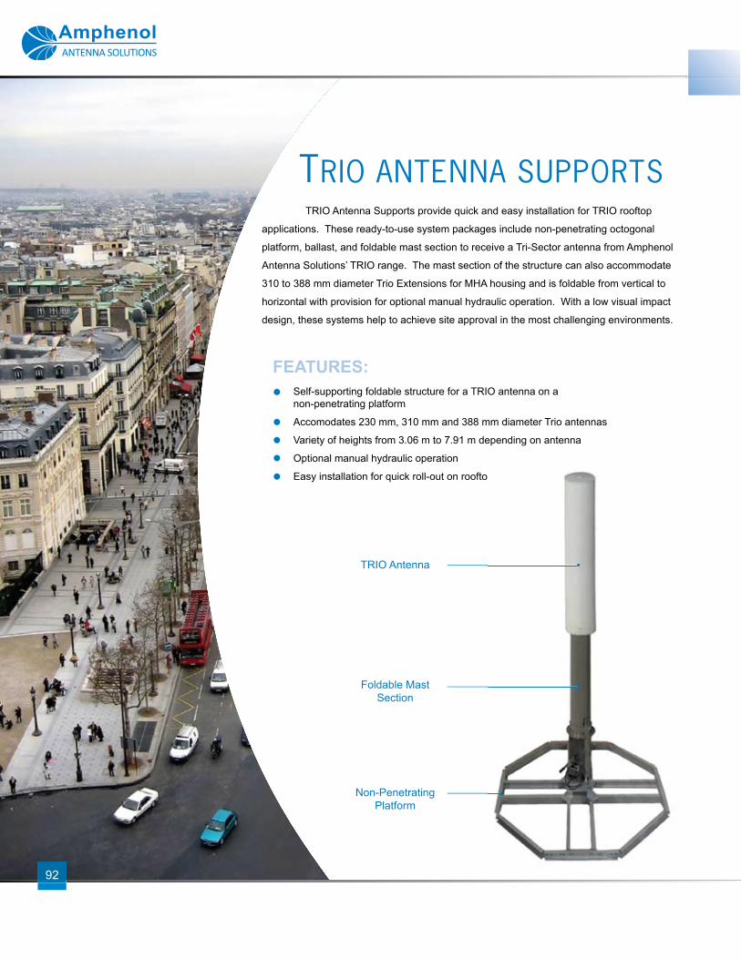
TRIO Antenna Supports provide quick and easy installation for TRIO rooftop
applications. These ready-to-use system packages include non-penetrating octogonal
platform, ballast, and foldable mast section to receive a Tri-Sector antenna from Amphenol
Antenna Solutions’ TRIO range. The mast section of the structure can also accommodate
310 to 388 mm diameter Trio Extensions for MHA housing and is foldable from vertical to
horizontal with provision for optional manual hydraulic operation. With a low visual impact
design, these systems help to achieve site approval in the most challenging environments.
TRIO ANTENNA SUPPORTS
FEATURES:Self-supporting foldable structure for a TRIO antenna on a non-penetrating platform
Accomodates 230 mm, 310 mm and 388 mm diameter Trio antennas
Variety of heights from 3.06 m to 7.91 m depending on antenna
Optional manual hydraulic operation
Easy installation for quick roll-out on rooftop
ANTENNA SOLUTIONS
92
Easy installation for quick roll-out on rooftop
TRIO Antenna
Foldable Mast Section
Non-Penetrating Platform

w w w . a m p h e n o l - a n t e n n a s . c o m
93
TRIO Antenna 3.0 m - 3.9 m 4.0 m - 4.9 m 5.0 m - 5.9 m 6.0 m - 6.9 m 7.0 m - 7.9 m
5880903 -- TRX-M2-03BTop Height: 4.42m
TRX-L2-13BTop Height: 5.42 m
TRX-L2-23BTop Height: 6.42 m
TRX-L6-33BTop Height: 7.42 m
5880903 + TRIO Extension -- -- TRX-L2-03CTop Height: 5.27 m
TRX-L2-13CTop Height: 6.27 m
TRX-L6-23CTop Height: 7.27 m
5860903 -- TRX-M2-03BTop Height: 4.42 m
TRX-L2-13BTop Height: 5.42 m
TRX-L2-23BTop Height: 6.42 m
TRX-L6-33BTop Height: 7.42 m
5860903 + TRIO Extension -- -- TRX-L2-03CTop Height: 5.27 m
TRX-L2-13CTop Height: 6.27 m
TRX-L6-23CTop Height: 7.27 m
5863903 TRX-M0-03BTop Height: 3.64 m
TRX-M2-13BTop Height: 4.64 m
TRX-L2-23BTop Height: 5.64 m
TRX-L4-33BTop Height: 6.64 m
TRX-L6-43BTop Height: 7.64 m
5863903 + TRIO Extension -- TRX-M2-03CTop Height: 4.49 m
TRX-L2-13CTop Height: 5.49 m
TRX-L2-23CTop Height: 6.49 m
TRX-L6-33CTop Height: 7.49 m
5177703 TRX-M0-03BTop Height: 3.06 m
TRX-M2-13BTop Height: 4.06 m
TRX-L2-23BTop Height: 5.06 m
TRX-L2-33BTop Height: 6.06 m
TRX-L6-43BTop Height: 7.06 m
5177703 + TRIO Extension TRX-M0-03CTop Height: 3.91 m
TRX-L2-13CTop Height: 4.91 m
TRX-L2-23CTop Height: 5.91 m
TRX-L4-33CTop Height: 6.91 m
TRX-L6-43CTop Height: 7.91 m
5162903 TRX-S0-03BTop Height: 3.34 m
TRX-M0-13BTop Height: 4.34 m
TRX-L2-23BTop Height: 5.34 m
TRX-L2-33BTop Height: 6.34 m
TRX-L6-43BTop Height: 7.34 m
5162903 + TRIO Extension -- TRX-M0-03CTop Height: 4.19 m
TRX-M2-13CTop Height: 5.19 m
TRX-L2-23CTop Height: 6.19 m
TRX-L4-33CTop Height: 7.19 m
5176903 TRX-S0-03BTop Height: 3.06 m
TRX-M0-13BTop Height: 4.06 m
TRX-M2-23BTop Height: 5.06 m
TRX-L2-33BTop Height: 6.06 m
TRX-L4-43BTop Height: 7.06 m
5176903 + TRIO Extension TRX-M0-03CTop Height: 3.91 m
TRX-M2-13CTop Height: 4.91 m
TRX-L2-23CTop Height: 5.91 m
TRX-L4-33CTop Height: 6.91 m
TRX-L6-43CTop Height: 7.91 m
5880713 -- TRX-M0-03BTop Height: 4.42 m
TRX-L2-13BTop Height: 5.42 m
TRX-L2-23BTop Height: 6.42 m
TRX-L6-33BTop Height: 7.42 m
5880713 + TRIO Extension -- -- TRX-L2-03CTop Height: 5.27 m
TRX-L2-13CTop Height: 6.27 m
TRX-L4-23CTop Height: 7.27 m
5863703 TRX-M0-03BTop Height: 3.65 m
TRX-M2-13BTop Height: 4.65 m
TRX-L2-23BTop Height: 5.65 m
TRX-L2-33BTop Height: 6.65 m
TRX-L6-43BTop Height: 7.65 m
5863703 + TRIO Extension -- TRX-M2-03CTop Height: 4.5 m
TRX-L2-13CTop Height: 5.5 m
TRX-L2-23CTop Height: 6.5 m
TRX-L6-33CTop Height: 7.5 m
5162703 TRX-S0-02ATop Height: 3.29 m
TRX-M0-12ATop Height: 4.29 m
TRX-M2-22ATop Height: 5.29 m
TRX-L2-32ATop Height: 6.29 m
TRX-L2-42ATop Height: 7.29 m
5176703 TRX-S0-02ATop Height: 3.06 m
TRX-M0-12ATop Height: 4.06 m
TRX-M2-22ATop Height: 5.06 m
TRX-L2-32ATop Height: 6.06 m
TRX-L2-42ATop Height: 7.06 m
Optional Hydraulic Cylinder and Pump TRX-HYD-01
TRIO Antenna Suppor t Model Numbers
Choose antenna, select needed height at the top, and fi nd antenna support model number option.

ANTENNA SOLUTIONS
Quoted performance parameters are provided to offer typical or range values only and may vary as a result of normal manufacturing and operational conditions. Extreme operational conditions and/or stress on structural supports is beyond our control. Such conditions may result in damage to this product. Improvements to product may be made without notice.
www.amphenol-antennas.com REV0510
94
TRIO Antenna Supports
Supporting Structure Mechanical Characteristics
Total height including antenna (TOP) 3.06 to 7.91 m (above roof)
Platform footprints: S size: M size: L size:
2040 x 2040 mm octogonal2544 x 2544 mm octogonal3378 x 3378 mm octogonal
BallastInstalled in the platform.
Ballast weight: 0 kg - 630 kg, depending on confi guration.Ballast is supplied and made of concrete blocks.
Mast section diameters: 230 mm dia TRIO 310 mm dia TRIO 388 mm dia TRIO
273 mm355 mm355 mm
Weights of steel parts: S size platform: M size platform: L size plateform: Masts:
419 kg508 kg624 kg
61 kg - 296 kg, depending on confi guration
Material: Platform and mast: Standard mast paint color:
Hot dipped galvanized steelRAL7035 (same as antenna shroud)
Other optional colors available on request
Wind Speed Operational: 160 km/hr Survival: 200 km/hr
Installation A detailed installation manual is supplied with the structure.
Hydraulic Mechanism
Option TRX-HYD-01
Manual hydraulic cylinder and pump
TRX-S0-02A* to TRX-L6-43C*Heights from 3.06 mm to 7.91 mm | Self-supporting | Foldable
* Refer to the TRIO Antenna Support Model Numbers table on page 93 for available options.

w w w . a m p h e n o l - a n t e n n a s . c o m
95
UNICELL Products

UNICELL enclosures are a family of cylindrical structures
designed to accept and conceal three standard Amphenol Antenna
Solutions dual polarized antennas. Like TRIO antennas, UNICELL
enclosures blend into their surroundings enabling rapid site approval
in sensitive urban environments.
UNICELL provides fl exibility. Flexibility to change the tilt
or pointing direction of an installed antenna; fl exibility to replace
an antenna with a different gain or azimuth beamwidth design; or
the fl exibility to change to completely new antenna technology as it
becomes available or as network requirements dictate. UNICELL
enclosures enable these changes without changing the visual
appearance of the site!
FEATURES:3-Sector antenna enclosures
2 diameters: 368 mm (14-inch) & 511 mm (20-inch)
Removable concealment panels
Easy fi eld access to internal antennas
Stackable to meet co-location requirements
Azimuth panning and mechanical tilt kits available
ANTENNA SOLUTIONS
UNICELL
96
the fl exibility to change to completely new antenna technology as it
becomes available or as network requirements dictate. UNICELL
enclosures enable these changes without changing the visual
appearance of the site!

97
w w w . a m p h e n o l - a n t e n n a s . c o m
Enclosure Family Diameter Applications / FeaturesUNICELL Model Number
1830 mm (72 inch)
2435 mm (96 inch)
2745 mm (108 inch)
UNICELL 14 368 mm (14.5 inch)
• GSM 1800, PCS 1900, UMTS, AWS
• Azimuth Swivel*UNX14-14 UNX14-19 --
UNICELL 20 511 mm (20.1 inch)
• All frequency bands
• ±30° Azimuth*
• 4° Mechanical tilt*
UNX20-14 UNX20-19 UNX20-25
* Feature is available in certain antenna and Unicell combinations only. Please refer to individual antenna datasheet for full application and features.
Accessory DescriptionAccessory Part Number for use with:
UNICELL 14 UNICELL 20
Flag Adapter KitCustom ball and truck assembly kit designed to simplify deployment of TRIO antennas as fl ag poles. Each kit includes a 305mm diameter anodized aluminum gold ball and a welded aluminum truck assembly.
UNX14-F UNX20-F
Lightning Protection Kit18-inch (460 mm) copper air fi nial with a 20 ft (6 m) section of #4 AWG braided copper cable pre-attached. The kit provides all necessary hardware for installation on top of the TRIO antenna.
UNX-LPK UNX-LPK
Mounting MastInterface fl ange welded to a 10 ft (3 m) steel mast pipe. The mast can be used with standard wall or pipe mounting kits to provide an inexpensive Trio mounting system. Custom lengths are available upon request.
UNX14-M-120 UNX20-M-120
Cable Access CanisterSteel construction with same diameter and appearance as Unicell structure to simplify cable installation and weatherproofi ng.
UNX14-C UNX20-C
Cable Support KitsThree steel plates able to mount inside a cable access canister with holes to accept standard coaxial cable snap hooks.
UNX14-CSK UNX20-CSK
Grounding Bus Bar KitsCopper grounding bar sized to fi t inside cable access canister cover with insulated supports.
UNX14-GBK UNX20-GBK
Cable Hanger KitBolt-on hooks that mount inside cable access canister to support standard cable hanging grips.
UNX-HK UNX-HK
Cable Support Kit(3 plates per kit)
Grounding Bus Bar(1 per kit)
Cable Hanger Kit(3 hook pairs per kit)
UNICELL Enclosures
UNICELL Accessor ies

Uni
cell
Model Number UNX14-14 UNX14-19 UNX20-14 UNX20-19 UNX20-25
800
MH
z
B800X065-13-x -- -- IncludedFixed Az / Fixed El
IncludedFixed Az / Fixed El --
B800X065-19-x -- -- -- IncludedFixed Az / Fixed El
IncludedFixed Az / Fixed El
B800X065-25-x -- -- -- -- IncludedFixed Az / Fixed El
BMX065X13x000 Included±25° Az / Fixed El
Included±25° Az / Fixed El
UNX20-AZ±30° Az / Fixed El
UNX20-AZ±30° Az / Fixed El --
BMX090X13x000 Included±25° Az / Fixed El
Included±25° Az / Fixed El
UNX20-AZ±30° Az / Fixed El
UNX20-AZ±30° Az / Fixed El --
1900
MH
z
PCSX065-13-x Included±30° Az / Fixed El
Included±30° Az / Fixed El
UNX20-TILT±30° Az / 0-4° El
UNX20-TILT±30° Az / 0-4° El --
PCSX065-18-x -- Included±30° Az / Fixed El -- UNX20-TILT
±30° Az / 0-4° ElUNX20-TILT
±30° Az / 0-4° El
PCSX065-18-xH -- -- -- UNX20-TILT±30° Az / 0-4° El
UNX20-TILT±30° Az / 0-4° El
PCSX065-19-x06 -- Included±25° Az / Fixed El -- UNX20-AZ
±30° Az / Fixed ElUNX20-AZ
±30° Az / Fixed El
PCSX085-13-x Included±30° Az / Fixed El
Included±30° Az / Fixed El
UNX20-TILT±30° Az / 0-4° El
UNX20-TILT±30° Az / 0-4° El --
PCSX085-18-x -- Included±30° Az / Fixed El -- UNX20-TILT
±30° Az / 0-4° ElUNX20-TILT
±30° Az / 0-4° El
PCSX085-19-x28 -- Included±25° Az / Fixed El -- UNX20-AZ
±30° Az / Fixed ElUNX20-AZ
±30° Az / Fixed El
1700
-217
0 M
Hz
W65-13-x010 Included±25° Az / Fixed El
Included±25° Az / Fixed El
UNX20-AZ±30° Az / Fixed El
UNX20-AZ±30° Az / Fixed El --
W65-19-A28 -- Included±25° Az / Fixed El -- UNX20-AZ
±30° Az / Fixed ElUNX20-AZ
±30° Az / Fixed El
W65-19-x06 -- Included±25° Az / Fixed El -- UNX20-AZ
±30° Az / Fixed ElUNX20-AZ
±30° Az / Fixed El
W85-13-x010 Included±25° Az / Fixed El
Included±25° Az / Fixed El
UNX20-AZ±30° Az / Fixed El
UNX20-AZ±30° Az / Fixed El --
W85-19-x28 -- Included±25° Az / Fixed El -- UNX20-AZ
±30° Az / Fixed ElUNX20-AZ
±30° Az / Fixed El
WBX033X14x050 -- -- UNX20-WBXFixed Az / Fixed El -- --
WBX033X17x050 -- -- -- UNX20-WBXFixed Az / Fixed El
UNX20-WBXFixed Az / Fixed El
WBX045X17x050 -- -- -- UNX20-WBXFixed Az / Fixed El
UNX20-WBXFixed Az / Fixed El
WBX065T17x050 -- -- -- UNX20-WBXFixed Az / Fixed El
UNX20-WBXFixed Az / Fixed El
WBX065T20x050 -- -- -- UNX20-WBXFixed Az / Fixed El
UNX20-WBXFixed Az / Fixed El
WBX065X10Fx00 Included±30° Az / Fixed El -- UNX20-TILT
±30° Az / 0-4° El -- --
WBX065X10x050 UNX14-WBX-AZ±30° Az / Fixed El -- UNX20-WBX-AZ
±30° Az / Fixed El -- --
WBX065X13Fx00 Included±30° Az / Fixed El
Included±30° Az / Fixed El
UNX20-TILT±30° Az / 0-4° El
UNX20-TILT±30° Az / 0-4° El --
WBX065X14x050 UNX14-WBX-AZ±30° Az / Fixed El
UNX14-WBX-AZ±30° Az / Fixed El
UNX20-WBX-AZ±30° Az / Fixed El
UNX20-WBX-AZ±30° Az / Fixed El --
WBX065X17x050 -- UNX14-WBX-AZ±30° Az / Fixed El -- UNX20-WBX-AZ
±30° Az / Fixed ElUNX20-WBX-AZ±30° Az / Fixed El
WBX065X18Fx00 -- Included±30° Az / Fixed El -- UNX20-TILT
±30° Az / 0-4° ElUNX20-TILT
±30° Az / 0-4° El
WBX065X20x050 -- UNX14-WBX-AZ±30° Az / Fixed El -- UNX20-WBX-AZ
±30° Az / Fixed ElUNX20-WBX-AZ±30° Az / Fixed El
WBX085X10Fx00 Included±30° Az / Fixed El -- UNX20-TILT
±30° Az / 0-4° El -- --
WBX085X13Fx00 Included±30° Az / Fixed El
Included±30° Az / Fixed El
UNX20-TILT±30° Az / 0-4° El
UNX20-TILT±30° Az / 0-4° El --
WBX085X18Fx00 -- Included±30° Az / Fixed El -- UNX20-TILT
±30° Az / 0-4° ElUNX20-TILT
±30° Az / 0-4° El
WWT65-13-x010 -- -- IncludedFixed Az / Fixed El
IncludedFixed Az / Fixed El --
WWT65-19-A28 -- -- -- IncludedFixed Az / Fixed El
IncludedFixed Az / Fixed El
WWT65-19-X06 -- -- -- IncludedFixed Az / Fixed El
IncludedFixed Az / Fixed El
1710
-217
0 /
2400
-270
0 M
Hz
DMX065X20x050 -- -- -- UNX20-WBXFixed Az / Fixed El
UNX20-WBXFixed Az / Fixed El
UNICELL and Antennas Compat ib i l i tyEach compatible UNICELL and Antenna sets will list the appropriate Mounting Kit and its azimuth & elevation features.
ANTENNA SOLUTIONS
98

ANTENNA SOLUTIONS
Quoted performance parameters are provided to offer typical or range values only and may vary as a result of normal manufacturing and operational conditions. Extreme operational conditions and/or stress on structural supports is beyond our control. Such conditions may result in damage to this product. Improvements to product may be made without notice.
REV0510 www.amphenol-antennas.com
99
Mechanical Specifi cations
Unicell Model Number (xx) UNX14-14 UNX14-19
Diameter of radome 368 mm 14.5 in 368 mm 14.5 in
Height 1829 mm 72 in 2438 mm 96 in
Weight (excluding antennas) 51.8 kg 114 lbs 60.9 kg 134 lbs
Antennas accommodated See Unicell and Antenna Compatibility table or individual antenna datasheet.
Azimuth swivel for antenna width < 7 in (177 mm) Yes* Yes*
Azimuth swivel for antenna width > 7 in (177 mm) No No
Mechanical tilt: No No
Stackable Yes Yes
Windload @ 100mph (160km/h) 363 N 82 lbf 484 N 109 lbf
Survival wind - single model 241 km/h 150 mph 241 km/h 150 mph
Survival wind - stacked models 241 km/h 150 mph 185 km/h 115 mph
*Azimuth swivel will depend on antenna model used. See Unicell and Antenna Compatibility table for available features.
Electrical Characteristics
Gain loss through radome < 0.3 dB
VSWR < 1.4:1 Max
Port to port isolation > 28 dB
Sector to sector isolation > 45 dB
Front to back ratio > 25 dB
Refer to individual antenna datasheets for all other electrical specifi cations.
Mounting Options Part Number Description
Mounting mast UNX14-M-120 Mounting mast, 120 in x 14 in dia
Flag adapter kit UNX14-F 14 in Unicell ball and truck assembly
Cable access canister UNX14-C 14 in Unicell Canister
Lightning protection kit UNX-LPK Copper air fi nial with 6m (20 ft) cable attached
Unicell Flange Interface:
9999
UNICELL 14
14-inch diameter Antenna Enclosure
UNX14-xx● 3-Sectors inside cylindrical enclosure
● Accommodates standard Amphenol Antenna Solutions cross-polarized antennas
● Independent azimuth adjustment per sector
● Stackable to satisfy co-location requirements
● Removable radome segments for easy fi eld access
Outside Diameter
Inside Diameter1
Bolt Circle Diameter
Inside Diameter2OD: 14.75 inches (374.7 mm)ID1: 10.00 inches (254 mm)ID2: 5.50 inches (139.7 mm)
BCD: 12 x 0.53 inch dia. (13.5 mm) on 12.0 inch dia. (304.8 mm) bolt circle
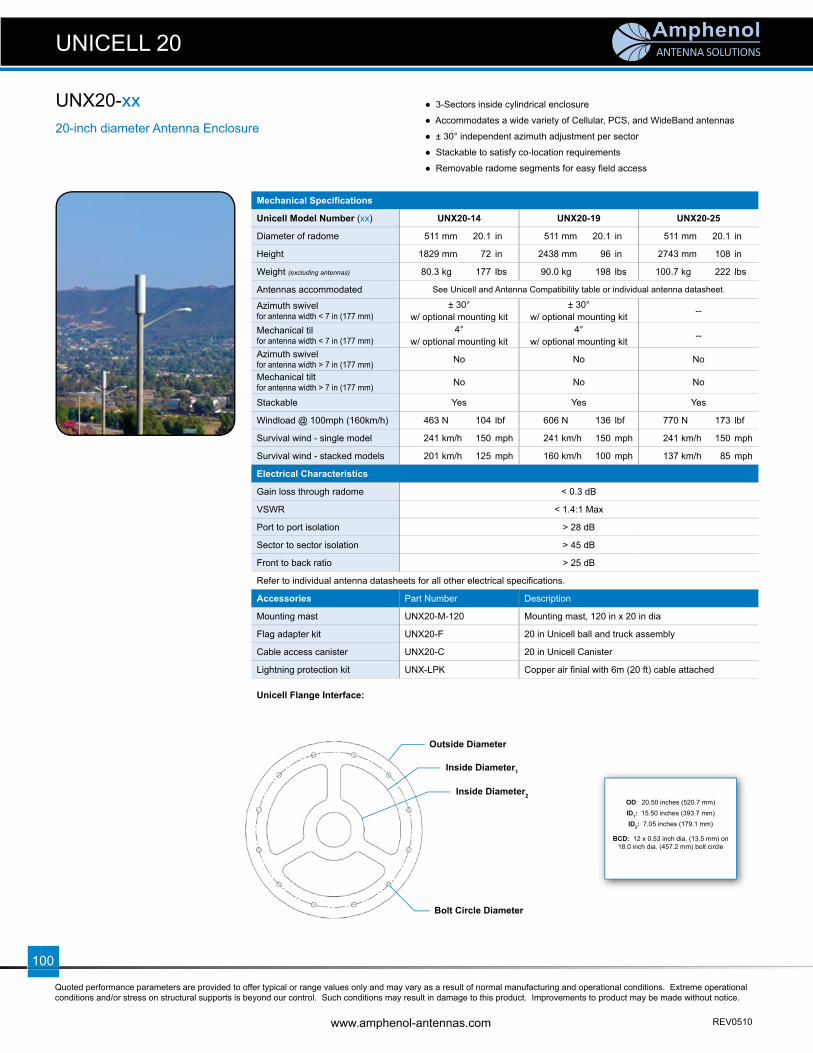
ANTENNA SOLUTIONS
Quoted performance parameters are provided to offer typical or range values only and may vary as a result of normal manufacturing and operational conditions. Extreme operational conditions and/or stress on structural supports is beyond our control. Such conditions may result in damage to this product. Improvements to product may be made without notice.
www.amphenol-antennas.com REV0510
100
Mechanical Specifi cations
Unicell Model Number (xx) UNX20-14 UNX20-19 UNX20-25
Diameter of radome 511 mm 20.1 in 511 mm 20.1 in 511 mm 20.1 in
Height 1829 mm 72 in 2438 mm 96 in 2743 mm 108 in
Weight (excluding antennas) 80.3 kg 177 lbs 90.0 kg 198 lbs 100.7 kg 222 lbs
Antennas accommodated See Unicell and Antenna Compatibility table or individual antenna datasheet.
Azimuth swivel for antenna width < 7 in (177 mm)
± 30° w/ optional mounting kit
± 30° w/ optional mounting kit --
Mechanical til for antenna width < 7 in (177 mm)
4° w/ optional mounting kit
4° w/ optional mounting kit --
Azimuth swivel for antenna width > 7 in (177 mm) No No No
Mechanical tiltfor antenna width > 7 in (177 mm) No No No
Stackable Yes Yes Yes
Windload @ 100mph (160km/h) 463 N 104 lbf 606 N 136 lbf 770 N 173 lbf
Survival wind - single model 241 km/h 150 mph 241 km/h 150 mph 241 km/h 150 mph
Survival wind - stacked models 201 km/h 125 mph 160 km/h 100 mph 137 km/h 85 mph
Electrical Characteristics
Gain loss through radome < 0.3 dB
VSWR < 1.4:1 Max
Port to port isolation > 28 dB
Sector to sector isolation > 45 dB
Front to back ratio > 25 dB
Refer to individual antenna datasheets for all other electrical specifi cations.
Accessories Part Number Description
Mounting mast UNX20-M-120 Mounting mast, 120 in x 20 in dia
Flag adapter kit UNX20-F 20 in Unicell ball and truck assembly
Cable access canister UNX20-C 20 in Unicell Canister
Lightning protection kit UNX-LPK Copper air fi nial with 6m (20 ft) cable attached
Unicell Flange Interface:
20-inch diameter Antenna Enclosure
UNX20-xx ● 3-Sectors inside cylindrical enclosure
● Accommodates a wide variety of Cellular, PCS, and WideBand antennas
● ± 30° independent azimuth adjustment per sector
● Stackable to satisfy co-location requirements
● Removable radome segments for easy fi eld access
UNICELL 20
OD: 20.50 inches (520.7 mm)ID1: 15.50 inches (393.7 mm)ID2: 7.05 inches (179.1 mm)
BCD: 12 x 0.53 inch dia. (13.5 mm) on 18.0 inch dia. (457.2 mm) bolt circle
Outside Diameter
Inside Diameter1
Bolt Circle Diameter
Inside Diameter2
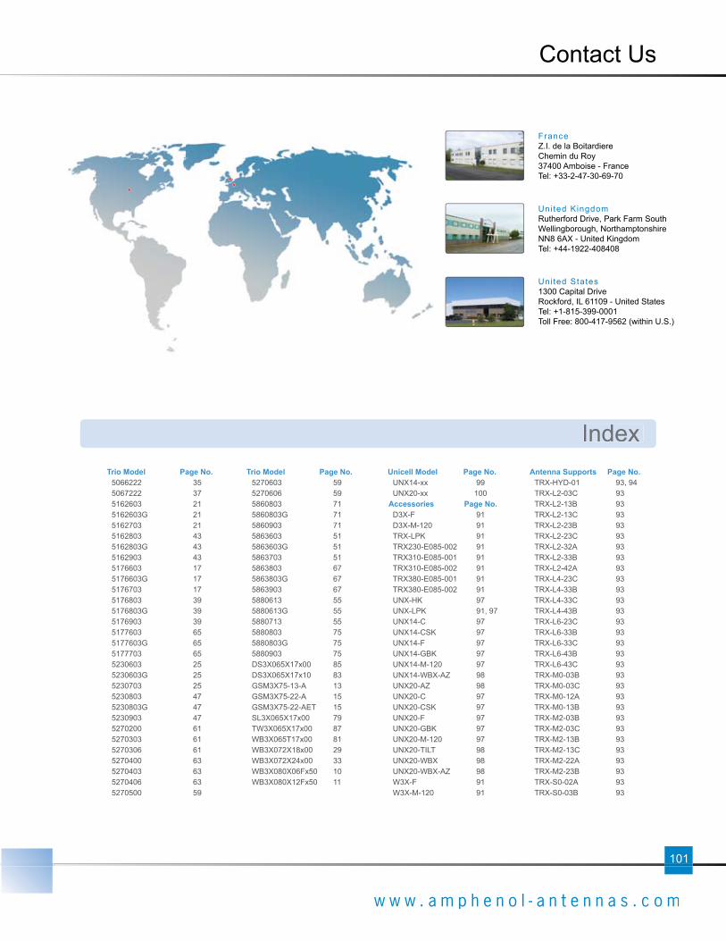
101
w w w . a m p h e n o l - a n t e n n a s . c o m
Contact Us
FranceZ.I. de la BoitardiereChemin du Roy37400 Amboise - FranceTel: +33-2-47-30-69-70
United KingdomRutherford Drive, Park Farm SouthWellingborough, Northamptonshire NN8 6AX - United KingdomTel: +44-1922-408408
United States1300 Capital DriveRockford, IL 61109 - United StatesTel: +1-815-399-0001Toll Free: 800-417-9562 (within U.S.)
Index
5066222 355067222 375162603 215162603G 215162703 215162803 435162803G 435162903 435176603 175176603G 175176703 175176803 395176803G 395176903 395177603 655177603G 655177703 655230603 255230603G 255230703 255230803 475230803G 475230903 475270200 615270303 615270306 615270400 635270403 635270406 635270500 59
5270603 595270606 595860803 715860803G 715860903 715863603 515863603G 515863703 515863803 675863803G 675863903 675880613 555880613G 555880713 555880803 755880803G 755880903 75DS3X065X17x00 85DS3X065X17x10 83GSM3X75-13-A 13GSM3X75-22-A 15GSM3X75-22-AET 15SL3X065X17x00 79TW3X065X17x00 87WB3X065T17x00 81WB3X072X18x00 29WB3X072X24x00 33WB3X080X06Fx50 10WB3X080X12Fx50 11
UNX14-xx 99UNX20-xx 100
Accessories Page No. D3X-F 91D3X-M-120 91TRX-LPK 91TRX230-E085-002 91TRX310-E085-001 91TRX310-E085-002 91TRX380-E085-001 91TRX380-E085-002 91UNX-HK 97UNX-LPK 91, 97UNX14-C 97UNX14-CSK 97UNX14-F 97UNX14-GBK 97UNX14-M-120 97UNX14-WBX-AZ 98UNX20-AZ 98UNX20-C 97UNX20-CSK 97UNX20-F 97UNX20-GBK 97UNX20-M-120 97UNX20-TILT 98UNX20-WBX 98UNX20-WBX-AZ 98W3X-F 91W3X-M-120 91
TRX-HYD-01 93, 94TRX-L2-03C 93TRX-L2-13B 93TRX-L2-13C 93TRX-L2-23B 93TRX-L2-23C 93TRX-L2-32A 93TRX-L2-33B 93TRX-L2-42A 93TRX-L4-23C 93TRX-L4-33B 93TRX-L4-33C 93TRX-L4-43B 93TRX-L6-23C 93TRX-L6-33B 93TRX-L6-33C 93TRX-L6-43B 93TRX-L6-43C 93TRX-M0-03B 93TRX-M0-03C 93TRX-M0-12A 93TRX-M0-13B 93TRX-M2-03B 93TRX-M2-03C 93TRX-M2-13B 93TRX-M2-13C 93TRX-M2-22A 93TRX-M2-23B 93TRX-S0-02A 93TRX-S0-03B 93
Trio Model Page No. Trio Model Page No. Unicell Model Page No. Antenna Supports Page No.

ANTENNA SOLUTIONS
w w w . a m p h e n o l - a n t e n n a s . c o m Issue 0510