Embed Size (px)
Citation preview
Accepted Manuscript
Antagonism between transition metal pro-oxidants in polyethylene films
Melissa Nikolic, Emilie Gauthier, Karina George, Gregory Cash, Martin D. de Jonge,Daryl L. Howard, David Paterson, Bronwyn Laycock, Peter J. Halley, Graeme George
PII: S0141-3910(12)00125-5
DOI: 10.1016/j.polymdegradstab.2012.03.036
Reference: PDST 6619
To appear in: Polymer Degradation and Stability
Received Date: 7 March 2012
Revised Date: 21 March 2012
Accepted Date: 22 March 2012
Please cite this article as: Nikolic M, Gauthier E, George K, Cash G, de Jonge MD, HowardDL, Paterson D, Laycock B, Halley PJ, George G, Antagonism between transition metalpro-oxidants in polyethylene films, Polymer Degradation and Stability (2012), doi: 10.1016/j.polymdegradstab.2012.03.036.
This is a PDF file of an unedited manuscript that has been accepted for publication. As a service toour customers we are providing this early version of the manuscript. The manuscript will undergocopyediting, typesetting, and review of the resulting proof before it is published in its final form. Pleasenote that during the production process errors may be discovered which could affect the content, and alllegal disclaimers that apply to the journal pertain.

MANUSCRIP
T
ACCEPTED
ACCEPTED MANUSCRIPT
1
PDST-D-12-00187R1 Ready
Antagonism between transition metal pro-oxidants in polyethylene films
Melissa Nikolic a*, Emilie Gauthier b, Karina George a,c, Gregory Cash b, Martin D. de Jonge d, Daryl L. Howard d, David Paterson d, Bronwyn Laycock a,b, Peter J. Halley b, Graeme George a. a Cooperative Research Centre for Polymers, School of Chemistry, Physics and Mechanical Engineering, Queensland University of Technology, Brisbane, 4001, Australia.
b Cooperative Research Centre for Polymers, School of Chemical Engineering, The University of Queensland, Brisbane, 4072, Australia.
c Current Address: Queensland Eye Institute, 41 Annerley Road, South Brisbane, Queensland 4101, Australia.
d Australian Synchrotron, 800 Blackburn Road, Clayton 3168, Australia.
Abstract: The oxidation of linear low density polyethylene (LLDPE) films containing the
combination of pro-oxidants titanium (IV) dioxide (TiO2) with either cobalt (II) stearate
(CoSt) or iron (II) stearate (FeSt) have been evaluated under accelerated photo- and thermo-
oxidative conditions as well as on outdoor weathering. LLDPE containing only surface-
compatibilised nano-TiO2 rapidly photo-whitens and embrittles at a low apparent extent of
oxidation (as measured by carbonyl index) due to formation of microscopic voids of ~150nm.
When CoSt was also included in the film, antagonism occurred shown by embrittlement
times longer by ~90%, higher carbonyl index and absence of film whitening. In contrast,
films containing TiO2/FeSt whitened during photo-oxidation and exhibited lower antagonism
with only 44% longer times to embrittlement and lower carbonyl index. Antagonism between
pro-oxidants was not observed under dark thermo-oxidative conditions. X-ray Fluorescence
Microspectroscopy elemental maps revealed that the TiO2 nanoparticles were spatially
correlated with iron and cobalt metal ions allowing scavenging of electrons and holes through
cycling of the redox states of the metal without producing radical species to initiate polymer
oxidation. It is suggested that the antagonism differences between TiO2/CoSt and TiO2/FeSt
pro-oxidants is related to the respective reduction potentials of Co3+/2+ and Fe3+/2+ and their
effect on the UV conduction and valence band edges of the TiO2 particle. In these ways the
photochemistry of TiO2 is suppressed and the photo-oxidative lifetime is governed by the
chemistry of the transition metal pro-oxidant.
Keywords: polyethylene; pro-oxidant; transition metal; photo-oxidation; thermo-oxidation;
TiO2

MANUSCRIP
T
ACCEPTED
ACCEPTED MANUSCRIPT
2
1.0 INTRODUCTION
Linear low density polyethylene (LLDPE) thin film is used for many applications and is not
easily degraded due to the inertness of the polyethylene chemical structure. Polyethylene is
traditionally disposed of by collection followed by incineration or burial in landfill. To
augment degradation and to counteract litter, pro-oxidants have long been researched in
which transition metal ions are used to promote auto-oxidation through catalytic
hydroperoxide decomposition [1]. These films are designed to degrade in the presence of
oxygen, heat and/or UV radiation into small low molecular weight fragments followed by
slow evolution into CO2. These pro-oxidant containing films are referred to as oxo-
degradable although recently it has been demonstrated that the residues after prolonged
oxidation may be assimilated by microbes and the term oxo-biodegradable has often been
used [1]. Of particular interest is the application of thin oxo-degradable polyolefin films in
agriculture to shorten the crop growing period and conserve water [2]. The tailored design of
such films alleviates the need for plastic collection and disposal at the end of their useful
lifetime, whilst maintaining optimal mechanical and barrier properties during their use. In
agricultural applications, the challenge is to achieve degradation both above and below the
ground in a timeframe compatible with the crop germination, growth and harvest cycle. For
the degradation requirements for LLDPE film to be achieved for this application, quite high
concentrations of typically more than one catalyst type are required. In this study we have
investigated oxo-degradable LLDPE films containing the photo-catalyst titanium (IV)
dioxide (TiO2) together with hydroperoxide decomposition catalysts, cobalt (II) stearate
(CoSt) and iron (II) stearate (FeSt).
As shown in equations (1), (2) & (3), transition metals such as cobalt (II) and/or iron (II) are
redox catalysts for hydroperoxide decomposition (particularly under dark thermo-oxidative
aging conditions) [3-10] and will be powerful prodegradants since the overall rate limiting
step in oxidation is the decomposition of hydroperoxides (POOH) [11]. It has been shown
that several transition metals, incorporated as the stearate into the polymer matrix during
processing, increase the rate of POOH decomposition by orders of magnitude, and
consequently accelerate the overall rate of polyethylene oxidation [3-5, 12-16].
−•++ ++→+ HOPOMPOOHM 32 (1)
MANUSCRIP
T
ACCEPTED
ACCEPTED MANUSCRIPT
3
+•++ ++→+ HPOMPOOHM 223
(2)
Overall
OHPOPOPOOH 222 ++→ ••
(3)
A well-known commercially available photoactive form of nano-TiO2, such as Degussa P25,
can be used to accelerate the photo-oxidation of polyethylene [17]. Degussa P25 TiO2 is a
mixture of crystalline structures that is approximately 80% anatase and 20% rutile with a
primary particle size of 21 nm [18, 19]. The anatase crystalline structure is the most
photoactive form of TiO2, due to the lower rate of electron-hole recombination compared to
rutile and brookite crystalline forms and also due to the higher aptitude for anatase to photo-
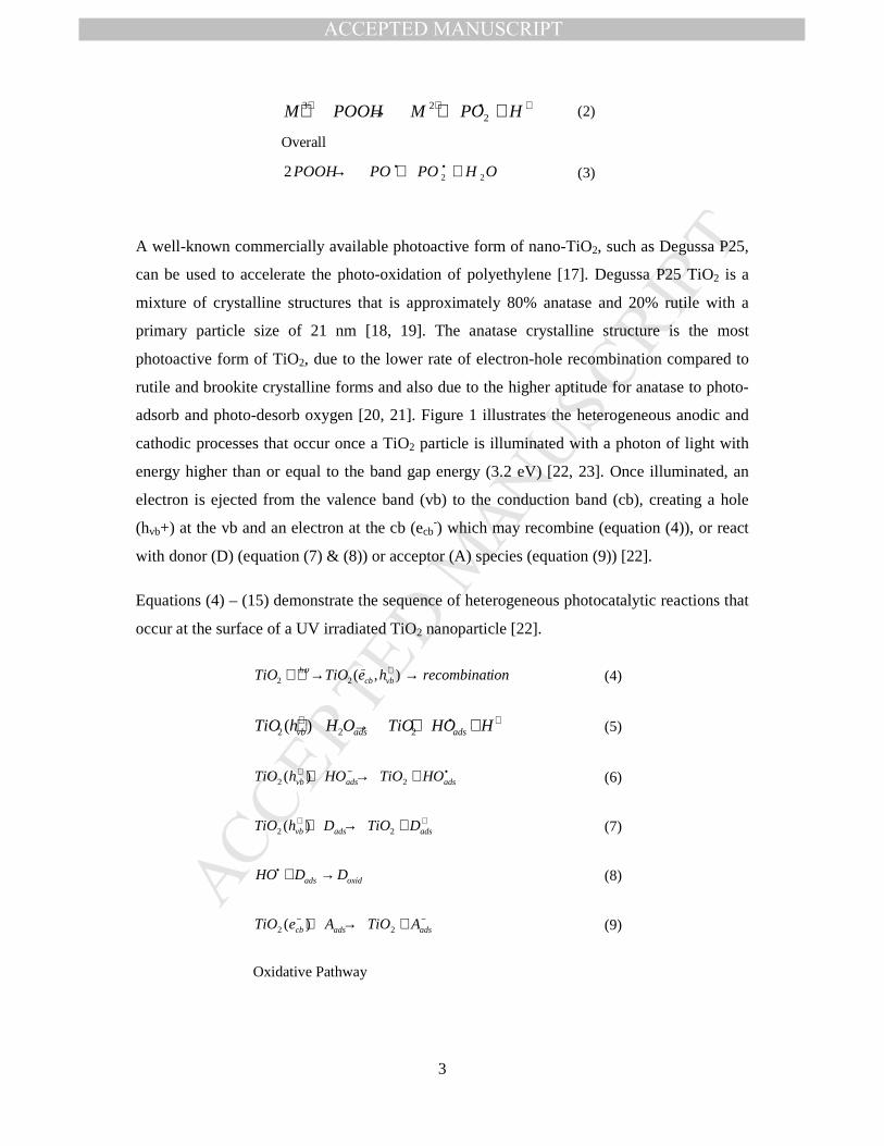
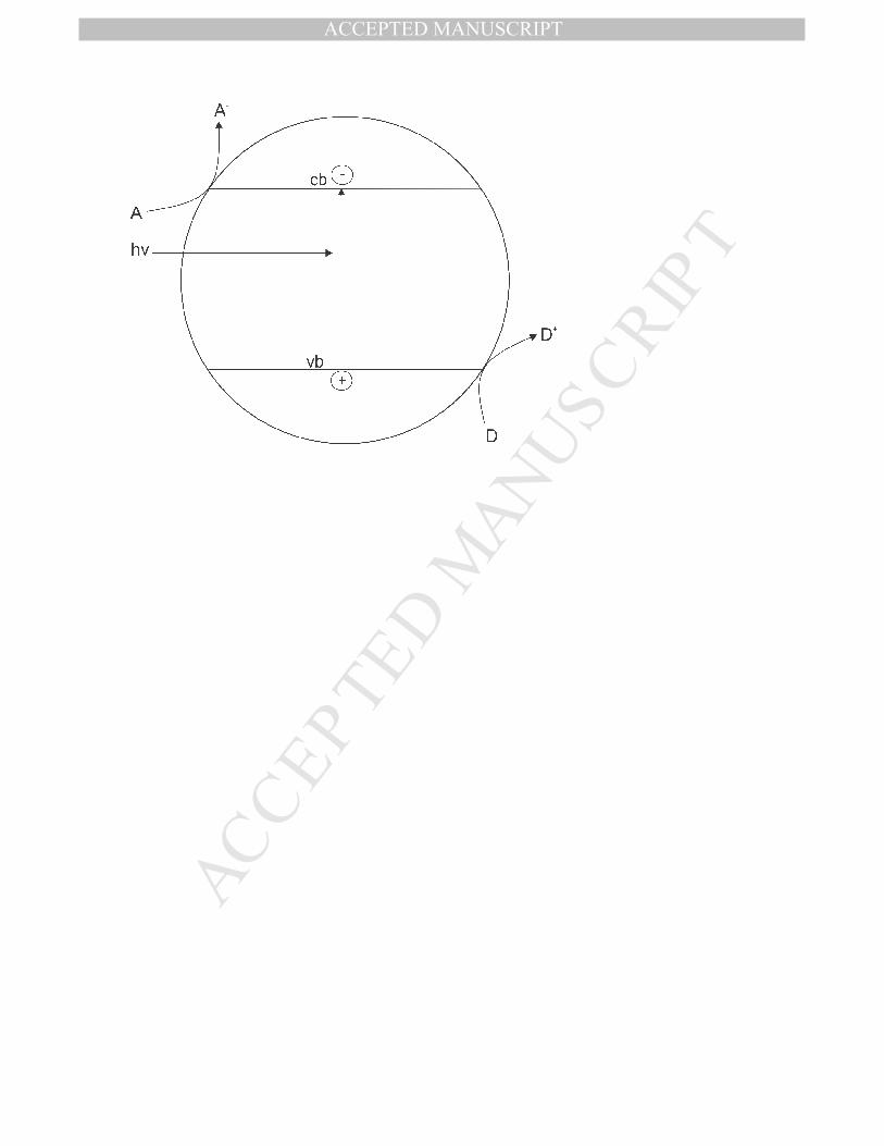
adsorb and photo-desorb oxygen [20, 21]. Figure 1 illustrates the heterogeneous anodic and
cathodic processes that occur once a TiO2 particle is illuminated with a photon of light with
energy higher than or equal to the band gap energy (3.2 eV) [22, 23]. Once illuminated, an
electron is ejected from the valence band (vb) to the conduction band (cb), creating a hole
(hvb+) at the vb and an electron at the cb (ecb-) which may recombine (equation (4)), or react
with donor (D) (equation (7) & (8)) or acceptor (A) species (equation (9)) [22].
Equations (4) – (15) demonstrate the sequence of heterogeneous photocatalytic reactions that
occur at the surface of a UV irradiated TiO2 nanoparticle [22].
ionrecombinatheTiOTiO vbcbh →→ +− ),(22υ
(4)
+•+ ++→+ HHOTiOOHhTiO adsadsvb 222 )( (5)
•−+ +→+ adsadsvb HOTiOHOhTiO 22 )( (6)
++ +→+ adsadsvb DTiODhTiO 22 )( (7)
oxidads DDHO →+• (8)
−− +→+ adsadscb ATiOAeTiO 22 )( (9)
Oxidative Pathway

MANUSCRIP
T
ACCEPTED
ACCEPTED MANUSCRIPT
4
+−••+− +↔+→++ HOHOTiOHOeTiO adscb 22222 )( (10)
OHHeTiOHO cb 222 )( →++ +−• (11)
22222 OOHHO +→• (12)
−•−• ++→+ HOOHOOOH 2222 (13)
•→+ HOhOH 222 υ (14)
−•− +→+ HOHOeTiOOH cb )(222 (15)
Ohtani et al. [24] have described the mechanism for the photo-oxidation of polyethylene in
the presence of TiO2, whereby a photo-generated hydroxyl radical abstracts a hydrogen from
the polymer, as shown in equation (16). The resulting carbon-centred polymer radical then
reacts with O2 and an auto-oxidation mechanism described in equations (16) – (21) follows:
(16)
(17)
(18)
(19)
(20)
(21)
Fa et al. [17, 19] have reported that unmodified hydrophilic TiO2 nanoparticles agglomerate
on the micrometer scale within the hydrophobic polyethylene matrix, thereby reducing the
photoactivity of the TiO2 due to a reduction in the interfacial area between the TiO2 particle
and the polyethylene. Accordingly they have dispersed the TiO2 in an oxidised polyethylene
wax, aiding dispersion and compatibilisation of the TiO2 in the polyethylene matrix. Well
dispersed Degussa P25 TiO2 within a polyethylene matrix results in film whitening during
photo-oxidation, due to the formation of microscopic voids which scatter light [24].

MANUSCRIP
T
ACCEPTED
ACCEPTED MANUSCRIPT
5
Whilst TiO2 has been shown to be a highly effective photo- pro-oxidant [17, 24, 25], it has
been shown to be very slow in oxidising LLDPE under dark thermo-oxidative conditions [26-
28]. The combined impact of photo-oxidation by TiO2 and the thermo-oxidation of transition
metal stearate pro-oxidants in polyethylene are required for a range of applications, including
crop propagation film; therefore the most obvious solution has been to include both pro-
oxidants (i.e., TiO2 and CoSt or FeSt) together in a polyethylene film. However, the impact
of these pro-oxidant combinations on the photo- and thermo-oxidation of polyethylene has
not been previously investigated and we report here conditions under which efficiency is
dramatically decreased i.e. combinations are antagonistic compared to the individual pro-
oxidants.
2.0 MATERIALS AND M ETHODS
2.1 Materials
A resin blend was used to form a base polyethylene matrix without pro-oxidant which is
suitable for agricultural applications as thin film. This mixture comprised two different
LLDPE resins (Dow Plastics), a low amount of LDPE (Qenos) and a low molecular weight
PIB as a tackifier (Daelim Corporation).
Cobalt (II) stearate and iron (II) stearate were both supplied by Alfa Caesar. The Aeroxide
Degussa P25 TiO2 was supplied by Evonik Australia Pty. Ltd. with a crystalline structure that
is approximately 80% anatase and 20% rutile, and an average primary particle size of 21 nm
[18].
2.2 Polymer Processing
Prior to blowing, the base resin masterbatch and pro-oxidant was homogenised by physical
mixing, followed by passing through a 40 L/D twin, co-rotating Entek extruder with 27 mm
diameter screws. The maximum temperature was 200°C and the screw speed was 50 rpm
giving a residence time between 3.75 and 4.0 minutes. The extrudate was passed through a
hot, die-faced pelletiser running at 200 rpm producing pellets of approximately 5 mm
diameter. A total of 300 g of pelletised material was then added to a 25 L/D Axon BX25
extruder fitted with a blowing die (215°C) of 40 mm in diameter and associated tower. The
single, 25 mm diameter Gateway screw had several cut flights towards the exit end and was
run at 28 rpm. The blow-up ratio was a maximum of 3. Table 1 describes the formulation
code that corresponds to the concentration of pro-oxidant in the final film formulation.

MANUSCRIP
T
ACCEPTED
ACCEPTED MANUSCRIPT
6
Prior to extrusion of films containing Degussa P25 TiO2, the P25 was mixed with
Sigmacote®, an organosilane obtained from Sigma Aldrich, in a weight ratio of 3.0:2.4 and
stirred in hexane to render the surface hydrophobic and improve its compatibility within the
polyethylene matrix. The solution was left to dry overnight and then placed under vacuum to
remove the residual solvent. Mobil DTE heavy oil (0.5%) was added during the extrusion of
TiO2 formulations to assist the binding of P25 to the resins. The film thickness of all films
was 12 ± 2 microns. The films containing organosilane-treated P25 were transparent,
indicating good dispersion of the nano-TiO2 in the film.
2.3 Accelerated Photo-oxidative Aging
Polyethylene film samples were mounted onto polystyrene 35 mm slide holders and exposed
to UV light using an Atlas Suntest CPS+ weathering chamber, fitted with a Xenon lamp
source and both coated quartz and solar standard filters. This filter combination was used to
simulate the solar global solar radiation outdoors. The samples were exposed to a total energy
across the spectral range of 300 – 800 nm of 765 W/m2, during a continuous 48 hour light
cycle and black panel temperature in the range of 49 ± 2oC.
2.4 Accelerated Thermo-oxidative Aging
After film blowing, duplicate samples of each film formulation were mounted onto
polystyrene 35 mm slide holders and were aged under ‘dark thermo-oxidative’ conditions in a
Contherm digital series fan-forced oven, maintained at 60°C, under conditions of 100%
humidity by being enclosed in desiccators with the base filled with 20 mL of MilliQ water.
Samples were withdrawn every 48 hours and evaluated for film embrittlement and analysed
using FTIR-ATR as described in Section 3.7. It was necessary to blot-dry samples with a lint-
free tissue prior to FTIR-ATR analysis, to remove residual water droplets from the surface of
the film. The carbonyl index (CI) was calculated as described in Section 3.7.
2.5 Outdoor Weathering
Two outdoor weathering trials were conducted at Pinjarra Hills, Qld, Australia. The first was
a six week study, investigating the changes in mechanical properties of LLDPE film
containing 1 wt% TiO2 pro-oxidant (1Ti/0Co/0Fe) and a control with no pro-oxidant which
were exposed above-ground on soil. A weather station (Campbell Scientific Inc.) was
installed at the trial site with a data logger, equipped with temperature and humidity probes

MANUSCRIP
T
ACCEPTED
ACCEPTED MANUSCRIPT
7
and a rain gauge. A pyranometer (Middleton SK08) was used to measure the total solar
global radiation across the spectral range 305 – 2800 nm and recorded with a data logger. The
films were exposed above-ground on an organic commercial garden soil (Table 2) and were
removed weekly to measure the change in the tensile mechanical properties in the film
(Section 3.8) using an Instron tensile testing machine.
The second study involved the above-ground exposure of 6 film formulations: control,
1Ti/0Co/0Fe, 0Ti/1000Co, 1Ti/1000Co, 0Ti/1000Fe and 1Ti/1000Fe. The films were
monitored every 2 days, for film whitening and embrittlement. The embrittlement point
resulted in fragmentation upon a gentle finger tap, equivalent to an elongation at break in the
film of 5% or less [29]. The total days, solar global radiation, rainfall and average daily
temperature for each formulation up until the embrittlement point was recorded and the
carbonyl index was measured at embrittlement using FTIR-ATR.
2.6 Ultraviolet-Visible (UV-Vis) Spectroscopy
Many of the films containing P25 nano-TiO2 whitened during UV exposure and the method
described by Ohtani et al. for characterising polyethylene film whitening was used [24]. The
percentage of light transmittance across the spectral range of 200 nm – 700 nm through each
film before aging and at embrittlement after photo-oxidation was measured with a Cary 50
Probe UV-Visible Spectrophotometer. The percentage of light transmittance at wavelength
585 nm was used as a benchmark to compare the degree of whitening between formulations.
2.7 Fourier Transform Infrared – Attenuated Total Reflectance Spectroscopy
(FTIR-ATR)
IR spectra from 4000 to 525 cm-1, were collected using a Nicolet 870 Nexus FTIR
spectrometer equipped with a Smart Endurance single bounce diamond-window ATR for 32
scans, 4 cm-1 resolution, a gain of 8 and a mirror velocity of 0.6329 cm/s. After initial
acquisition using OMNIC software (Thermo-Nicolet, Madison, WI), spectra were
manipulated and plotted using a GRAMS/32 software package (Galactic Corp., Salem, NH).
The measurement time for each spectrum was approximately 60 seconds. The carbonyl index
(CI) peak was measured as the height of the C=O stretching peak at 1714 cm-1 divided by the
C-H peak height at 1463cm-1.

MANUSCRIP
T
ACCEPTED
ACCEPTED MANUSCRIPT
8
2.8 Tensile Testing
Film samples were cut into 25 × 22 mm strips with the long axis in the transverse direction.
Analysis was performed on an Instron 5543 instrument fitted with a 50N load cell, equipped
with pneumatic grips. The cross head speed of 250 mm/min was chosen based on the ASTM
D882 standard test method. Reported values are quoted as the average ± 1 standard deviation
of 6 - 8 replicate samples.
2.9 Scanning Electron Microscopy (SEM)
Samples of film formulations were placed on carbon conducting pads that were then applied
to an aluminium stub. The samples were sputter-coated with platinum for 100 seconds using
an SPI coater. The Pt-coated samples were examined with a JEOL 6460 SEM (Tungsten
filament). An accelerating voltage of 10kV was used with a working distance of 10-12 mm.
Spot sizes are shown on each micrograph as the number on the right next to “SEI”. Smaller
spot sizes (25 -35) were used for magnifications above ×5000 and larger spot sizes (around
45) for lower magnifications. All images were captured as TIF files at the highest resolution
possible. TIF files were post-processed with Paint Shop Pro Version 5 to adjust brightness
and contrast where needed.
3.10 X-ray Fluorescence Microspectroscopy & Co XANES
X-ray fluorescence microscopy (XFM) and bulk X-ray Absorption Near-Edge Structure
(XANES) were employed in fluorescence mode at the XFM beamline at the Australian
Synchrotron. The XFM beamline is an undulator beamline with a Si(111) monochromator
and a nominal energy resolution (∆E/E) of 2 x 10⁻⁴ at 10 keV [30]. The distribution of Co, Fe
and Ti were mapped at 10 keV throughout the thickness of films 1Ti/1000Co and 1Ti/1000Fe
over an area of 28 µm x 25 µm with a step size of 0.2 µm x 0.1 µm (H x V) and with a
focussed x-ray spot size of 600 nm x 300 nm (H x V). After mapping, Co XANES
measurements were performed with a large beam to avoid any artefacts associated with the
relative motion of the x-ray beam to the Co nanoparticles. Co XANES were acquired from
formulation 1Ti/1000Co after no UV exposure, 6 days accelerated UV exposure and until
embrittlement after an elemental mapping experiment. The XANES spectra were collected
between 7690 and 7790 eV with a step of 1 eV.
MANUSCRIP
T
ACCEPTED
ACCEPTED MANUSCRIPT
9
3.0 RESULTS & DISCUSSION
3.1 Defining Embrittlement
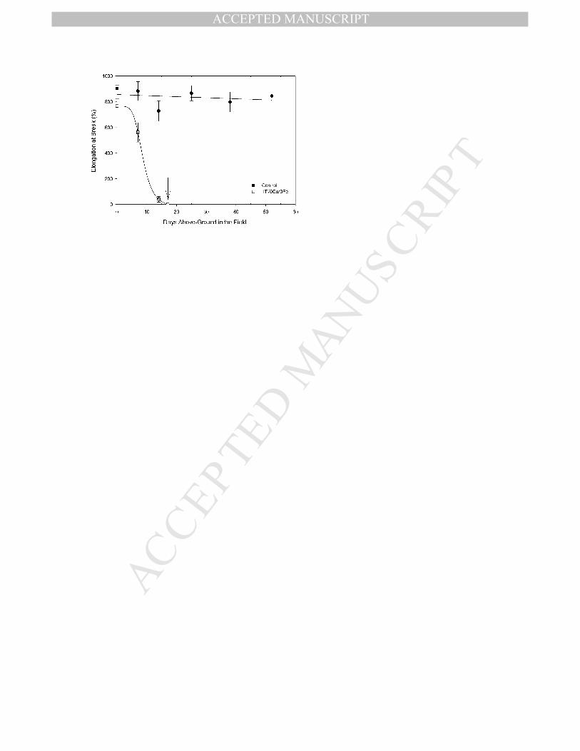
Figure 2 illustrates the progression of the decrease in tensile elongation at break for the
formulation containing only TiO2 (1Ti/0Co/0Fe), compared to the control film during
weathering. The arrow indicates the embrittlement point reached by the LLDPE film, where
the elongation was less than 5% after 17 days. At this point the film fractures and fragments
under light load. When used as agricultural film the embrittled material cannot be removed
and fragments in place. This process is distinguished from film splitting in which there is a
loss of properties only in one direction and the split agricultural film may remain intact on the
soil without fragmenting.
3.2 Accelerated Laboratory Photo-Oxidation
3.2.1 Film Embrittlement
The time to film embrittlement for photo-oxidised polyethylene formulations containing
combinations of TiO2 and CoSt pro-oxidants are summarised in Table 3 and the most rapid
degradation (9 days) occurs with the addition of either 1% TiO2 or 1000ppm Co2+. However
when the two pro-oxidants were combined at the same concentration of each, the time to
embrittle almost doubles to 17 days rather than reducing even further as might be expected.
While this is still faster than the 55 days taken for the original LLDPE to degrade, it indicates
that there is antagonism when the two pro-oxidants are used together.
The extent of this antagonism has been assessed by reducing the concentration of CoSt while
holding the TiO2 concentration at 1%. From Table 3 it may be seen that there is an initial
reduction in the time to embrittlement when the concentration is reduced to 600-800ppm
Co2+ but it then increases progressively so that even catalytic concentrations of CoSt
(200ppm Co2+) increase the time to embrittle of formulations containing 1% TiO2. Indeed the
lifetime of this combination (21 days) is very close to that with 200ppm Co2+ alone (23 days)
suggesting that the photoactivity of the TiO2 is almost totally lost.
In order to determine if this effect is restricted to CoSt, the time to embrittlement for the
photo-oxidation of LLDPE formulations containing a combination of TiO2 and FeSt pro-
oxidants was also measured (Table 3). The presence of 1000 ppm Fe2+ in combination with
1% TiO2 only increased the time to embrittle to 13 days from 9 days for the TiO2 alone

MANUSCRIP
T
ACCEPTED
ACCEPTED MANUSCRIPT
10
suggesting that not all TiO2 photoactivity is lost. FeSt is a much weaker pro-oxidant than
CoSt and when 1000ppm Fe2+ alone is added to LLDPE the time to embrittle is 28 days.
3.2.2 Film Whitening
The percentage of light transmission at 585 nm was recorded for each formulation before and
after embrittlement and is shown in Table 4. A whitened film was defined by 5% or less light
transmittance throughout the film. The percentage of light transmittance at embrittlement was
used as an indirect measure of TiO2 photoactivity within the film, where lack of film
whitening during photo-oxidation suggested that the photoactivity of the TiO2 had been
reduced.
At embrittlement, the formulation with 1% TiO2 alone was uniformly white with a light
transmission of 0.2% at 585 nm. For formulations containing CoSt in combination with TiO2,
the light transmittance was comparable at time zero and embrittlement, between 59 – 68%
(Table 4). LLDPE alone and containing only CoSt as pro-oxidant showed a reduction in the
light transmittance at embrittlement, but remained transparent.
When FeSt was used in combination with TiO2, the light transmission at 585 nm at
embrittlement was reduced to 2.4 %, compared to 0.2 % for TiO2 alone, however to the eye it
was apparent that both films whitened. The time to whiten was 38% of the time to embrittle
compared to 33% for the sample with TiO2 alone. These results suggest that the extent of
whitening of the LLDPE by the TiO2 was not significantly impacted upon by the FeSt
consistent with the observation from the data for time to embrittlement that not all TiO2
photoactivity has been lost.
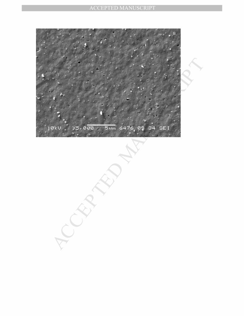
SEM analysis performed on photo-oxidised films 1Ti/0Co/0Fe and 1Ti/1000Fe at
embrittlement (Figure 3 A & B) revealed a high number of microscopic voids with an
average diameter of approximately 150 nm. It is also apparent from the upper section of
Figure 3A that the microscopic voids have coalesced to form a crack corresponding to the
onset of embrittlement. The scattering of light by the microscopic voids formed during photo-
oxidation is responsible for the whitening of these films [24]. In contrast to the films
containing only TiO2, examination of an embrittled, photo-oxidised film with a formulation
of 1Ti/1000Co (Figure 3 C), revealed very few microscopic voids consistent with reduced
photoactivity of the TiO2 in the presence of CoSt.
MANUSCRIP
T
ACCEPTED
ACCEPTED MANUSCRIPT
11
The absence of film whitening for TiO2/CoSt formulations may be related to the redox
potential of Co3+/2+ metal ions and their effect on TiO2 band edge potentials. Ohtani et al. [24]
found that heterogeneous photo-induced TiO2 oxidation reactions, shown above through
reactions (10) – (15), are responsible for film whitening. When these heterogeneous reactions
were inhibited, photo-oxidation of the polyethylene progressed through homogeneous
reactions leading to uniform degradation and no whitening.
Antagonism effects have been reported between combinations of TiO2 and dissolved metal
ions during the photo-oxidation of phenolic compounds in aqueous solutions [31-36]. This
antagonism effect has been described mechanistically by Co3+ and Fe3+ competing with
oxygen for ecb- at the surface of the excited TiO2 particle, which consequently reduces the
hydroxyl radical formation that would normally occur via equations (4) – (6). Additionally,
the oxidation of the Co2+ or Fe2+ metal ions by a hydroxy radical or hole (hvb+ ) at the surface
of the excited TiO2 particle, reduces the overall concentration of hydroxyl radicals as shown
in equation (22) [22]:
+++− →⋅+ nvb
n MHOhM )()1(
(22)
where n = 3; M is Co or Fe
While this mechanism explains the significant decrease in the rate of embrittlement for
TiO2/CoSt formulations, it does not explain why the antagonism between TiO2 and CoSt was
far more severe than that between TiO2 and FeSt, despite evidence of oxidation by the
formation of carbonyl products.
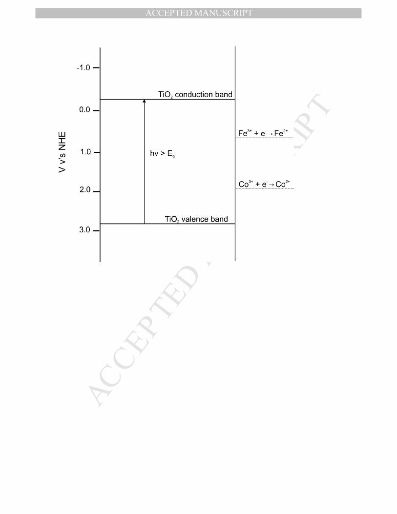
Brezova et al. [31] found that the influence of metal ions in the presence of TiO2 on phenol
photo-oxidation could be estimated by comparing the standard reduction potential of the
metal ions, such as Co2+/3+ and Fe2+/3+, to the band edge potentials of TiO2, shown in Figure
4. The higher redox potential for Co3+/2+ (1.92 V) compared with Fe3+/2+ (0.77 V) [37],
indicates that Co3+ has a higher affinity for the ecb- ejected from the TiO2 particle and can be
more easily reduced compared to Fe3+. Equations (23) and (24) show the transfer of ecb- from
the UV irradiated TiO2 particle to the transition metal ion and hvb+ of the TiO2 particle [31]:
+−−+ →+ )1(ncb
n MeM (23)

MANUSCRIP
T
ACCEPTED
ACCEPTED MANUSCRIPT
12
+++− →+ nvb
n MhM )1( (24)
where M = Co or Fe; n = 3
The cycling of these redox side reactions shown in equation (23) and (24), will decrease the
concentration of hydroxyl radicals formed, so reducing the rate of polyethylene photo-
oxidation. Effectively the initiation of heterogeneous photo-oxidation at the surface of the
TiO2 nanoparticle has been shut down and the only oxidation reactions seen are initiated by
the metal salt. This suggests close association between the TiO2 nanoparticle and the metal
stearate in the solid film to enable this scavenging to take place.
4.3 X-ray Fluorescence Microscopy
XFM was used to evaluate the distribution of metal ions throughout the films after UV
irradiation. Formulation 1Ti/1000Co (Figure 5) shows the distribution of Co, Fe and Ti ions
within the film, as well as an overlay image showing their combined distributions. Scatter
plots of these relative concentrations (i.e., normalised to the Ti-ion concentration) describe
the co-localisation in greater detail, and are included as supplementary information.
Examination of the overlay map in Figure 5 and scatter plot SI1 suggest that Ti and Co are
strongly co-localised within the film. In addition, the maximum intensity scale for the Fe map
shows that there is a low concentration of Fe present compared to Co (less than tenfold the
maximum of Co) that mostly appears to follow the same spatial distribution, which are likely
to be impurities. There are also domains of high density Fe (clearly visible in the overlay as
bright blue regions). This low concentration of Fe may be real; alternatively, it is possible
that the high concentration impurities result in artefactual elemental cross-talk between Co
and Fe. The combination of the co-localization of Ti and Co metal ions and the higher redox
potential of the Co3+/2+ would provide an ideal platform for photo-antagonistic reactions to
occur.
The elemental and overlay maps for formulation 1Ti/1000Fe (Figure 6) again shows the co-
localisation of Fe, Co and Ti metal ions within the polyethylene film. The maximum intensity
scale for the Co map compared to Fe and associated scatter plots (SI 3 & 4 in the
supplementary material), suggest a Co impurity within the film, with some domains
composed almost entirely of Co (bright red in overlay). There is also the possibility of some
fluorescence line overlap resulting in a low-level Co co-localisation. Photo-oxidation results
on formulation 1Ti/1000Fe showed minimal inhibition on the photochemistry of the TiO2,

MANUSCRIP
T
ACCEPTED
ACCEPTED MANUSCRIPT
13
which may be related to the lower redox potential of Fe3+/2+ compared to Co3+/2+, even though
there is evidence of Ti and Fe metal ion co-localisation in the film.
4.4 X-Ray Absorption Near-Edge Structure (XANES)
Fluorescence X-ray Absorption Near-Edge Structure (XANES) was used as a spectroscopic
tool to reveal changes in metal ion oxidation state and coordination chemistry of Co metal
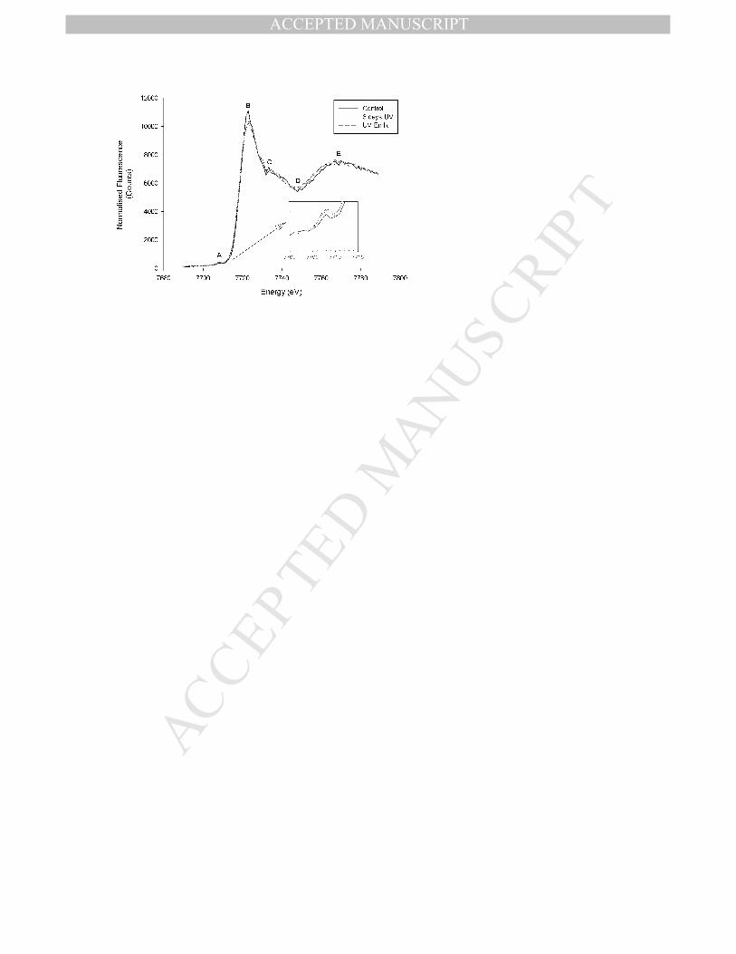
ions in the presence of TiO2 after UV exposure. Figure 7 shows the Co XANES spectra
obtained for formulation 1Ti/1000Co before UV exposure (control), after accelerated UV
exposure for 6 days and at embrittlement. The characteristic features of the Co XANES
spectra are shown by (A) the small pre-edge peak at 7708 eV, (B) the white line intensity at
7723 eV, (C) the shoulder region after the white line, (D) the post-edge minima between
7749 – 7750 eV and (E) the large oscillation mostly attributed to the multiple scattering from
neighbouring bonded groups, such as Co-O [38].
Previous studies on tetrahedral Co2+ complexes have attributed the pre-edge absorptions at ≈
7708 eV to the transition of the 1s electron to the 3d molecular orbital [38-41]. For both UV
exposed traces, the spectra suggest there may be a marginal increase in the fluorescence
intensity of this pre-edge feature, compared to the control. The white line peak at 7723 eV for
a Co2+ complex of tetrahedral coordination has been reported as the transition of the 1s
electron to the 4p molecular orbital [38]. Hall et al. [42, 43] and Robinet et al. [38] have
reported that the absorption intensity of the pre-edge and white line are influenced by the
coordination number of the Co metal ion complex.
The observed decrease in the white-line intensity at 7723 eV and the accompanying increase
in the pre-edge intensity following UV exposure suggests a decrease in the cobalt
coordination number with UV exposure [44], consistent with change in the coordination from
the octahedral CoSt to a tetrahedral complex (possibly involving hydroperoxides) after UV
irradiation. The Co XANES spectra also show there has been no change in oxidation state
with UV exposure, as previous investigations on the oxidation and reduction of Co metal ions
have shown a shift in the energy of the white line peak is expected for changes in Co
oxidation state [38, 39]. There is therefore no evidence for direct chemical reaction between
CoSt and TiO2 nanoparticles. The antagonism most likely arises from the competition
between the closely associated metal ions for the photo-generated electrons and holes at the
nanoparticle surface so the energy absorbed by the TiO2 is leading to cycling through the
oxidation states of the metal without generation of reactive species to degrade the polymer.

MANUSCRIP
T
ACCEPTED
ACCEPTED MANUSCRIPT
14
4.5 Accelerated Laboratory Thermo-Oxidation
4.5.1 Film Embrittlement on heating at 60oC in the dark
Accelerated dark thermo-oxidative experiments were performed on TiO2/CoSt formulations
to evaluate the impact of the combination of TiO2 and CoSt pro-oxidants in the absence of
UV on the oxidation of polyethylene. These simulate the expected performance of the pro-
oxidants when the agricultural film is buried. The results (Table 5) show that combinations of
TiO2 and CoSt pro-oxidants are not antagonistic under dark thermo-oxidative conditions and
there was no change in film transparency at embrittlement. This result is in agreement with
previous studies, where it was found that TiO2 was a poor pro-oxidant under dark thermo-
oxidative conditions and films did not whiten [26-28].
For these formulations, the time to embrittlement was controlled by the concentration of CoSt
in the film but the dependence was not linear with concentration. The rate of polyethylene
thermo-oxidation was not significantly different for formulations containing 1% TiO2 with up
to 600ppm Co2+. A significant decrease in the time to embrittlement was observed with 800
ppm Co2+, however at 1000 ppm Co2+ the time to embrittlement increased. According to
Black et al. [11], the rate of POOH decomposition is dependent on the pro-oxidant
concentration in the LLDPE. The POOH decomposition is accelerated up to a critical
concentration of Co2+, above which the Co2+ may act as a stabiliser [11]. The mechanism for
catalytic decomposition requires complexation of hydroperoxide by the Co2+ and the
competing stabilisation reaction can occur only when the concentration of CoSt is greater
than that of hydroperoxide [11]. The data in Table 5 suggest that above 800 ppm Co2+ the
critical concentration of CoSt is being approached so that there is a stabilising effect that
reduces the overall pro-oxidant efficiency of the formulation.
4.6 Carbonyl Index at Embrittlement
The carbonyl index (CI) at embrittlement for TiO2/CoSt and TiO2/FeSt formulations aged
under accelerated photo-oxidative and thermo-oxidative conditions are summarised in Table
6. Figure 8 shows the FTIR-ATR spectra for the photo-oxidised films at the point of
embrittlement. LLDPE without pro-oxidant showed a similar CI at embrittlement after photo-
and thermo-oxidation. When a pro-oxidant is present this is no longer seen. For all TiO2-
containing formulations, the CI at embrittlement differed significantly with type of aging,
suggesting mechanistic changes. For example, photo-oxidised 1Ti/0Co/0Fe exhibited a

MANUSCRIP
T
ACCEPTED
ACCEPTED MANUSCRIPT
15
significantly lower CI at embrittlement (0.06) compared to both a control film (0.22) and also
one that has been thermo-oxidized (0.11).
One explanation for this lower CI at embrittlement is the photolysis of carbonyl products
(such as carboxylic acids) to volatile products (equation (25)). As shown earlier, SEM
micrographs confirmed the presence of microscopic voids in photo-oxidised film
1Ti/0Co/0Fe, suggesting the formation of volatile species from the polymer in the vicinity of
the nanoparticle surface leading to a lower concentration of oxidation products in the polymer
on photo-degradation.
2, 2 CORHRCOOH TiOh + → υ (25)
Once cobalt stearate is present in the formulation and photo-antagonism is seen (Table 3), the
concentration of oxidation products at embrittlement approximately doubles. At the same
time there is no whitening of the film and the production of microscopic voids is greatly
reduced so that at 1000ppm Co (1Ti/1000Co) no voids are seen (Figure 3C) indicating that
the photochemistry of the TiO2 is totally suppressed. The extent of oxidation at embrittlement
is much higher, being greater than when only the CoSt pro-oxidant is present.
Details of the carbonyl region of photo-oxidised formulations at embrittlement are shown in
Figure 8 (with the baselines offset for clarity). The control film (upper curve) shows a
pronounced acid (1712 cm-1) peak as indicated by the CI value (0.22) in Table 6, as well as a
neighbouring ester (1735 cm-1) shoulder of significant intensity (CI1735 = 0.20). In contrast,
formulations containing pro-oxidant showed an acid and ester shoulder peak of lower
intensity compared to the control. Further examination of the IR spectra of pro-oxidant-
containing films has revealed that both whitening formulations 1Ti/0Co/0Fe and 1Ti/1000Fe
showed a very similar carbonyl distribution profile with comparable low intensities of acid
and virtually no esters, due to the volatilization of carbonyl products to CO2. In contrast, the
photo-antagonistic formulation 1Ti/1000Co showed a carbonyl profile in close agreement
with the CoSt and FeSt alone, with a higher intensity of acid and ester products compared to
whitening formulations.
For thermo-oxidised formulations containing 1 wt% TiO2 with varying concentrations of
Co2+, a general trend was observed where the CI at embrittlement increased as the
concentration of Co2+ increased within the formulation to values much higher than the control

MANUSCRIP
T
ACCEPTED
ACCEPTED MANUSCRIPT
16
film. Allen et al. [28] investigated the thermo-oxidation of a series of LDPE films containing
different grades of TiO2 in an air vented oven at 90oC, measuring the concentration of
hydroperoxides formed during thermo-oxidation. The results from their study on organically
coated anatase and rutile TiO2 nanoparticles dispersed in polyethylene, showed substantially
higher concentrations of POOH in the polyethylene plus TiO2, compared to polyethylene
alone. If this is also occurring in our system, these hydroperoxides are more efficiently
decomposed as the concentration of Co2+ is increased up to a critical concentration, resulting
in an increase in CI at embrittlement. Interestingly, this did not result in a faster time to
embrittlement for films containing 1 wt% TiO2 and CoSt under the conditions used in our
study.
3.3 Outdoor Weathering
An outdoor weathering trial was conducted on TiO2/CoSt and TiO2/FeSt formulations to
determine whether antagonism on polyethylene photo-oxidation is also observed under the
lower dose rate of natural weathering. The results (Table 7) clearly show antagonism between
pro-oxidants, confirming this effect is not an artefact of the accelerated photo-oxidation
conditions.
In agreement with accelerated photo-oxidation experiments, formulations 1Ti/1000Co and
1Ti/1000Fe showed longer times to embrittlement compared to TiO2 alone, indicating a
reduction in the photoactivity of TiO2 within the film. The absence of film whitening and
higher CI at embrittlement for formulation 1Ti/1000Co (0.33) compared to 1% TiO2 alone
(0.14) provides further evidence of antagonism between TiO2 and CoSt pro-oxidants. Also in
agreement is the whitening and lower CI at embrittlement for formulation 1Ti/1000Fe (0.08)
compared to 1% TiO2 alone. Clearly, the antagonism is so severe that the time taken to
embrittle for 1% TiO2 in the presence of 1000ppm FeSt or CoSt is effectively independent of
the presence of TiO2. However the whitening of the films with FeSt indicates that
heterogeneous photo-initiation has occurred so the lack of an effect on time to embrittle is
inconsistent with observations under accelerated photo-oxidation.
A comparison of the time to embrittlement acceleration factors for film aged outdoors to
accelerated photo-oxidation trials were variable (ranging from 1.3 to 2.7) and could not be
correlated with pro-oxidant formulation. However, differences in the weathering factors
outdoors, such as high humidity, rainfall events and fluctuations in UV and temperature
compared to the controlled and constant UV, temperature and humidity conditions during

MANUSCRIP
T
ACCEPTED
ACCEPTED MANUSCRIPT
17
accelerated tests, would contribute to these differences in acceleration factors between
formulations.
4.0 CONCLUSIONS
The effect of a combination of TiO2 with CoSt or FeSt pro-oxidants in polyethylene is to
reduce the efficiency of photo-oxidation without affecting the thermo-oxidation efficiency.
Differences in the standard reduction potential for Co3+/2+ (1.92 V) and Fe3+/2+ (0.77 V) and
their effect on the UV band edge of a TiO2 nanoparticle, may be responsible for the
differences in the antagonistic impact on the accelerated photo-oxidation of the LLDPE.
Antagonistic effects are also seen on outdoor ageing but with differences between the
magnitude of the effects. The effect of the transition metal salt is to switch off photo-
initiation by hydroxyl radicals generated at the surface of the nanoparticle by scavenging of
electrons and holes by the redox reactions of the transition metals. To achieve optimum
control of the lifetime of agricultural film both above and below ground, strategies are
required to overcome this antagonism by limiting direct physical interaction between the pro-
oxidants.
5.0 ACKNOWLEDGEMENTS
The authors would like to thank and acknowledge the Cooperative Research Centre for
Polymers and Integrated Packaging for financial support of this work. Dr Chun-Liang Yeh,
Mr Marcus Leong and Dr Babak Radi are acknowledged with thanks for performing FTIR-
ATR characterisation. The XFM & XANES part of this research was undertaken on the XFM
beamline at the Australian Synchrotron, Victoria, Australia.
MANUSCRIP
T
ACCEPTED
ACCEPTED MANUSCRIPT
18
REFERENCES
[1] Wiles D, Scott G. Polyolefins with controlled environmental degradability. Polymer Degradation and Stability. 2006;91:1581-92. [2] Billingham NC, Bonora M, De Corte D. Environmentally Degradable Plastics Based on Oxo- Biodegradation of Conventional Polyolefins. In: Chiellini E, Solaro R, editors. Biodegradable Polymers and Plastics. New York: Kluwer Academic/Plenum Publishers; 2003. [3] Roy PK, Surekha P, Rajagopal C, Choudhary V. Thermal degradation studies of LDPE containing cobalt stearate as pro-oxidant. eXPRESS Polym Lett. 2007;1:208-16. [4] Roy PK, Surekha P, Rajagopal C, Choudhary V. Degradation behaviour of linear low-density polyethylene films containing pro-oxidants under accelerated test conditions. Journal of Applied Polymer Science. 2008;108:2726-33. [5] Roy PK, Surekha P, Raman R, Rajagopal C. Investigating the role of metal oxidation state on the degradation behaviour of LDPE. Polymer Degradation and Stability. 2009;94:1033-9. [6] Khabbaz F, Albertsson A-C, Karlsson S. Chemical and morphological changes of environmentally degradable polyethylene films exposed to thermo-oxidation. Polymer Degradation and Stability. 1998;63:127-38. [7] Vogt NB, Kleppe EA. Oxo-biodegradable polyolefins show continued and increased thermal oxidative degradation after exposure to light. Polymer Degradation and Stability. 2009;94:659-63. [8] Brebu M, Bhaskar T, Murai K, Muto A, Sakata Y, Uddin MA. Thermal degradation of PE and PS mixed with ABS-Br and debromination of pyrolysis oil by Fe- and Ca-based catalysts. Polymer Degradation and Stability. 2004;84:459-67. [9] Barrkumarakulasinghe SA. Modelling the thermal oxidative-degradation kinetics of polyethylene film containing metal pro-oxidants. Polymer. 1994;35:995-1003. [10] Koutný M, Václavková T, Matisová-Rychlá L, Rychlý J. Characterization of oxidation progress by chemiluminescence: A study of polyethylene with pro-oxidant additives. Polymer Degradation and Stability. 2008;93:1515-9. [11] Black JF. Metal-Catalyzed Autoxidation. The Unrecognized Consequences of Metal- Hydroperoxide Complex Formation. Journal of the American Chemical Society. 1978;100:527-35. [12] Roy P, Surekha P, Rajagopal C, Choudhary V. Effect of cobalt carboxylates on the photooxidative degradation of low-density polyethylene. Part-I. Polymer Degradation and Stability. 2006;91:1980-8. [13] Roy PK, Surekha P, Rajagopal C, Chatterjee SN, Choudhary V. Studies on the photo-oxidative degradation of LDPE films in the presence of oxidized polyethylene. Polymer Degradation and Stability. 2007;92:1151-60. [14] Roy PK, Surekha P, Rajagopal C, Chatterjee SN, Choudhary V. Accelerated aging of LDPE films containing cobalt complexes as pro-oxidants. Polymer Degradation and Stability. 2006;91:1791-9. [15] Roy PK, Surekha P, Rajagopal C, Raman R, Choudhary V. Study on the degradation of low density polyethylene in the presence of cobalt stearate and benzil. Journal of Applied Polymer Science. 2006;99:236-43. [16] Maji S, Chattopadhyay PK, Khastgir D, Chattopadhyay S. Transition metal catalyzed oxidative aging of low density polyethylene: effect of manganese (III) acetate. Journal of Polymer Research. 2010;17:325-34. [17] Fa W, Yang C, Gong C, Peng T, Zan L. Enhanced photodegradation efficiency of polyethylene- TiO2 nanocomposite film with oxidized polyethylene wax. Journal of Applied Polymer Science. 2010;118:378-84. [18] Evonik Industries. AEROXIDE® TiO2 P 25, 2008, www.aerosil.com [19] Fa W, Zan L, Gong C, Zhong J, Deng K. Solid-phase photocatalytic degradation of polystyrene with TiO2 modified by iron (II) phthalocyanine. Applied Catalysis B: Environmental. 2008;79:216- 23.
MANUSCRIP
T
ACCEPTED
ACCEPTED MANUSCRIPT
19
[20] Sclafani A, Herrmann JM. Comparison of the photoelectronic and photocatalytic activities of various anatase and rutile forms of titania in pure liquid organic phases and in aqueous solutions. Journal of Physical Chemistry. 1996;100:13655 - 61. [21] Allen NS, Edge M, Verran J, Stratton J, Maltby J, Bygott C. Photocatalytic titania based surfaces: Environmental benefits. Polymer Degradation and Stability. 2008;93:1632-46. [22] Litter MI. Heterogeneous photocatalysis: Transition metal ions in photocatalytic systems. Applied Catalysis B: Environmental. 1999;23:89-144. [23] Almquist CB, Biswas P. Role of Synthesis Method and Particle Size of Nanostructured TiO2 on Its Photoactivity. Journal of Catalysis. 2002;212:145-56. [24] Ohtani B, Adzuma S, Nishimoto S, Kagiya T. Photocatalytic degradation of polyethylene film by incorporated extra fine particles of titanium dioxide. Polymer Degradation and Stability. 1992;35:53-60. [25] Yang R, Christensen PA, Egerton TA, White JR, Maltby A. Spectroscopic studies of photodegradation of polyethylene films containing TiO2 nanoparticles. Journal of Applied Polymer Science. 2011;119:1330-8. [26] Allen NS, Edge M, Sandoval G, Ortega A, Liauw CM, Stratton J, et al. Interrelationship of spectroscopic properties with the thermal and photochemical behaviour of titanium dioxide pigments in metallocene polyethylene and alkyd based paint films: micron versus nanoparticles. Polymer Degradation and Stability. 2002;76:305-19. [27] Allen NS, Katami H. Comparison of various thermal and photoageing conditions on the oxidation of titanium dioxide pigmented linear low density polyethylene films. Polymer Degradation and Stability. 1996;52:311-20. [28] Allen NS, Khatami H, Thompson F. Influence of titanium dioxide pigments on the thermal and photochemical oxidation of low density polyethylene film. European Polymer Journal. 1992;28:817-22. [29] ASTM Standard D3826-98, 2008, "Standard practice for determining degradation end point in degradable polyethylene and polypropylene using a tensile test", ASTM International, West Conshohocken, PA, 2008, 10.1520/D3826-98R08, www.astm.org [30] Paterson D, de Jonge MD, Howard DL, Lewis W, McKinlay J, Starritt A, et al. The X-ray Fluorescence Microscopy Beamline at the Australian Synchrotron. 2011:219-22. [31] Brezova V, Blazkova A, Borosova E, Ceppan M, Fiala R. The influence of dissolved metal ions on the photocatalytic degradation of phenol in aqueous TiO2 suspensions. Journal of Molecular Catalysis A: Chemical. 1995;98:109-16. [32] Wei T-T, Wan C-C. Kinetics of photocatalytic oxidation of phenol on TiO2 surface. Journal of Photochemistry and Photobiology A: Chemistry. 1992;69:241-9. [33] Wei T-T, Wang Y-Y, Wan C-C. Photocatalytic oxidation of phenol in the presence of hydrogen peroxide and titanium dioxide powders. Journal of Photochemistry and Photobiology A: Chemistry. 1990;55:115-26. [34] Vinu R, Madras G. Kinetics of Simultaneous Photocatalytic Degradation of Phenolic Compounds and Reduction of Metal Ions with Nano-TiO2. Environmental Science and Technology. 2008;42:913-19. [35] Zhao B, Mele G, Pio I, Li J, Palmisano L, Vasapollo G. Degradation of 4-nitrophenol (4-NP) using Fe-TiO2 as a heterogeneous photo-Fenton catalyst. Journal of Hazardous Materials. 2010;176:569-74. [36] Bouras P, Lianos P. Synergy effect in the combined photodegradation of an azo dye by titanium dioxide photocatalysis and photo-Fenton oxidation. Catalysis Letters. 2008;123:220-5. [37] Vanysek P. Electrochemical Series. In: Haynes WM, Lide DR, editors. CRC Handbook of Physics and Chemistry. 91st ed. Gaithersburg, Maryland, USA: CRC; 2011. [38] Robinet L, Spring M, Pagès-Camagna S, Vantelon D, Trcera N. Investigation of the Discoloration of Smalt Pigment in Historic Paintings by Micro-X-ray Absorption Spectroscopy at the Co K-Edge. Analytical Chemistry. 2011;83:5145-52. [39] Behrens P. X-ray absorption spectroscopy in chemistry. II X-ray absorption near edge structure. Trends in Analytical Chemistry. 1992;11:237 - 44. [40] Sano M. XANES Study at the Co K Absorption Edge in a Series of Cobalt(III) Complexes. Inorganic Chemistry. 1988;27:4249-53.
MANUSCRIP
T
ACCEPTED
ACCEPTED MANUSCRIPT
20
[41] Bonnitcha PD, Hall MD, Underwood CK, Foran GJ, Zhang M, Beale PJ, et al. XANES investigation of the Co oxidation state in solution and in cancer cells treated with Co(III) complexes. J Inorg Biochem. 2006;100:963-71. [42] Hall MD, Foran GJ, Zhang M, Beale PJ, Hambley TW. XANES Determination of the Platinum Oxidation State Distribution in Cancer Cells Treated with Platinum(IV) Anticancer Agents. J Am Chem Soc. 2003;125:7524-5. [43] Hall MD, Underwood CK, Failes TW, Foran GJ, Hambley TW. Using XANES to Monitor the Oxidation State of Cobalt Complexes. Aust J Chem. 2007;60:180-3. [44] Wilke M, Farges F, Petit P-E, Brown GE, Martin F. Oxidation state and coordination of Fe in minerals: An Fe K-XANES spectroscopic study. American Mineralogist. 2001;86:714–30.

MANUSCRIP
T
ACCEPTED
ACCEPTED MANUSCRIPT
21
Figure 1. Heterogeneous processes that occur when a TiO2 particle is illuminated with a photon of energy greater than or equal to the band gap energy [22]. Reproduced with permission from Elsevier.
Figure 2. The change in elongation at break for a TiO2-containing film (1Ti/0Co/0Fe) and a control aged outdoors above-ground on soil. The arrow denotes the embrittlement point.
Figure 3. SEM micrographs of photo-oxidised LLDPE films at embrittlement. A – 1Ti/0Co/0Fe; B - 1Ti/1000Fe & C - 1Ti/1000Co.
Figure 4. Schematic representation of the vb and cb of TiO2 with corresponding photochemical generation of reduction (e-) and oxidation sites (h+) along with the reduction potentials of Co and Fe [31]. Reproduced with permission from Elsevier.
Figure 5. The distribution of Co, Fe and Ti metal ions as well as an overlay distribution map of the 3 metal ions throughout the cross-section of film 1Ti/1000Co after UV irradiation. The images have been scaled to better indicate distribution and are not quantitative. Most particles here indicate a constant admixture of Co, Fe, and Ti although there is also a significant population of with almost pure Fe (blue in overlay).
SI 1. Scatter plot of Co vs. Ti metal ion concentration both normalised to the maximum concentration of Ti in the XFM map of formulation 1Ti/1000Co.
SI 2. Scatter plot of Fe vs. Ti metal ion concentration both normalised to the maximum concentration of Ti in the XFM map of formulation 1Ti/1000Co.
Figure 6. The distribution of Co, Fe and Ti metal ions as well as an overlay distribution map of the 3 metal ions throughout the cross-section of film 1Ti/1000Fe after UV irradiation. The images have been scaled to better indicate distribution and are not quantitative. Most particles here indicate a constant admixture of Co, Fe, and Ti with a few showing a predominance of Co (red in overlay).
SI 3. Scatter plot of Co vs. Ti metal ion concentration both normalised to the maximum concentration of Ti in the XFM map of formulation 1Ti/1000Fe.
SI 4. Scatter plot of Fe vs. Ti metal ion concentration both normalised to the maximum concentration of Ti in the XFM map of formulation 1Ti/1000Fe.
Figure 7. Co XANES spectra of formulation 1Ti/1000Co before UV exposure (control), after 6 days UV exposure and at embrittlement after UV exposure. (A) Pre-edge peak at 7708 eV; (B) White line peak at 7723 eV; (C) Shoulder peak following white line corresponding to the electronic structure and coordination of the Co; (D) Post-edge minima between 7749 – 7750 eV; (E) Large oscillation at the start of the EXAFS region [38]. The inset shows a magnification of the pre-edge region.
Figure 8. The carbonyl region of the FT-IR spectrum of LLDPE films after photo-oxidation to embrittlement.

MANUSCRIP
T
ACCEPTED
ACCEPTED MANUSCRIPT
22
Table 1. Concentrations of pro-oxidants in the final film formulations.
Formulation
Code
TiO2
Wt%
[Co2+]*
ppm
[Fe2+]**
ppm
Control - - -
0Ti/200Co - 200 -
0Ti/1000Co - 1000 -
0Ti/1000Fe - - 1000
1Ti/0Co/0Fe 1 - -
1Ti/200Co 1 200 -
1Ti/300Co 1 300 -
1Ti/400Co 1 400 -
1Ti/600Co 1 600 -
1Ti/800Co 1 800 -
1Ti/1000Co 1 1000 -
1Ti/1000Fe 1 - 1000 *Incorporated as cobalt (II) stearate **Incorporated as iron (II) stearate

MANUSCRIP
T
ACCEPTED
ACCEPTED MANUSCRIPT
23
Table 2. Properties of the commercial garden soil used in outdoor weathering trials.
Texture Coarse Sandy Clay Loam
Colour Grey
pH 7.2
Total Organic Carbon (%) 2.1
Organic Matter (%) 4.5

MANUSCRIP
T
ACCEPTED
ACCEPTED MANUSCRIPT
24
Table 3. Photo-oxidation of polyethylene containing pro-oxidants in an Atlas Suntest.
Formulation Code
Time to
Emb. (Days)
± SD (Days)
Time to Whiten. (Days)
Control 55 1 -
0Ti/200Co 23 1 -
0Ti/1000Co 9 1 -
0Ti/1000Fe 28 1 -
1Ti/0Co/0Fe 9 1 3
1Ti/200Co 21 1 -
1Ti/300Co 20 2 -
1Ti/400Co 21 1 -
1Ti/600Co 14 2 -
1Ti/800Co 12 2 -
1Ti/1000Co 17 1 -
1Ti/1000Fe 13 1 5

MANUSCRIP
T
ACCEPTED
ACCEPTED MANUSCRIPT
25
Table 4. The change in transmittance at 585 nm for TiO2/CoSt and TiO2/FeSt films at time 0 and at embrittlement after aging under accelerated photo-oxidative conditions.
Formulation
Code
t = 0 At embrittlement
%T
585 nm
±
SD
%T
585 nm
±
SD
Control 86.4 2.4 76.3 0.7
0Ti/200Co 85.4 0.8 68.2 0.3
0Ti/1000Co 80.3 0.6 77.1 3.0
0Ti/1000Fe 82.2 0.3 71.3 3.1
1Ti/0Co/0Fe 77.6 0.3 0.2 0.1
1Ti/200Co 73.8 0.7 63.7 1.0
1Ti/300Co 71.0 0.3 60. 9 3.7
1Ti/400Co 67.2 0.9 59.0 0.4
1Ti/600Co 70.7 0.0 63.8 2.4
1Ti/800Co 66.0 1.0 68.0 0.2
1Ti/1000Co 70.1 0.4 67.3 0.4
1Ti/1000Fe 75.7 2.6 2.4 0.8

MANUSCRIP
T
ACCEPTED
ACCEPTED MANUSCRIPT
26
Table 5. Thermo-oxidation of polyethylene film formulations aged at 60oC and 100%
relative humidity.
Formulation Code
Time to Emb.
(Days)
± SD (Days)
Control 111 1
0Ti/200Co 19 1
0Ti/1000Co 13 1
1Ti/0Co/0Fe 95 1
1Ti/200Co 18 2
1Ti/300Co 18 2
1Ti/400Co 17 1
1Ti/600Co 18 2
1Ti/800Co 11 2
1Ti/1000Co 15 3

MANUSCRIP
T
ACCEPTED
ACCEPTED MANUSCRIPT
27
Table 6. The CI at embrittlement for TiO2/CoSt and TiO2/FeSt formulations aged under
accelerated laboratory thermo-oxidative and photo-oxidative conditions.
Photo-Oxidation Thermo-Oxidation
Formulation CI at Emb.
± SD CI at Emb.
± SD
Control 0.22 0.03 0.23 0.01
0Ti/200Co 0.06 0.01 0.40 0.01
0Ti/1000Co 0.10 0.01 0.21 0.04
0Ti/1000Fe 0.11 0.01 0.14 0.01
1Ti/0Co/0Fe 0.06 0.01 0.11 0.01
1Ti/200Co 0.08 0.01 0.11 0.01
1Ti/300Co 0.08 0.01 0.22 0.01
1Ti/400Co 0.09 0.01 0.29 0.01
1Ti/600Co 0.09 0.02 0.43 0.03
1Ti/800Co 0.10 0.02 0.40 0.02
1Ti/1000Co 0.13 0.01 0.36 0.01
1Ti/1000Fe 0.07 0.01 0.50 0.06

MANUSCRIP
T
ACCEPTED
ACCEPTED MANUSCRIPT
28
Table 7. Outdoor aging data for film exposed above-ground at a trial site at Pinjarra
Hills, Queensland, Australia.
Formulation Code
Total Days
to Whiten
Total Solar
Energy to Whiten (MJ/m2)
Total Days
to Emb.
Total Solar
Energy to Emb.
(MJ/m2)
CI at
Emb.
Avg. Air T (OC)
Total Rainfall (mm)
Control - - 86 ± 2 1772 ± 41 0.18 ± 0.01 22 ± 3 198
1Ti/0Co/0Fe 3 ± 1 66 ± 23 16 ± 2 346 ± 44 0.14 ± 0.01 19 ± 1 3
0Ti/1000Co - - 24 ± 2 521 ± 40 0.41 ± 0.03 22 ± 2 16
1Ti/1000Co - - 23 ± 3 465 ± 79 0.33 ± 0.04 22 ± 2 16
0Ti/1000Fe - - 34 ± 2 749 ± 64 0.12 ± 0.01 23 ± 2 16
1Ti/1000Fe 15 ± 1 290 ± 17 34 ± 5 743 ± 112 0.08 ± 0.01 23 ± 2 16
MANUSCRIP
T
ACCEPTED
ACCEPTED MANUSCRIPT
MANUSCRIP
T
ACCEPTED
ACCEPTED MANUSCRIPT

MANUSCRIP
T
ACCEPTED
ACCEPTED MANUSCRIPT
MANUSCRIP
T
ACCEPTED
ACCEPTED MANUSCRIPT

MANUSCRIP
T
ACCEPTED
ACCEPTED MANUSCRIPT
MANUSCRIP
T
ACCEPTED
ACCEPTED MANUSCRIPT

MANUSCRIP
T
ACCEPTED
ACCEPTED MANUSCRIPT

MANUSCRIP
T
ACCEPTED
ACCEPTED MANUSCRIPT
MANUSCRIP
T
ACCEPTED
ACCEPTED MANUSCRIPT

MANUSCRIP
T
ACCEPTED
ACCEPTED MANUSCRIPT