Embed Size (px)
Citation preview

ANSYS
®
Workbench™
Tutorial
Structural & Thermal Analysis using the
ANSYS Workbench Release 11.0 Environment
Kent L. Lawrence
Mechanical and Aerospace Engineering University of Texas at Arlington
SDC
Schroff Development Corporation
www.schroff.com
www.schroff-europe.com
PUBLICATIONS
Copyrighted Material
Copyrighted
Material
Copyrighted Material
Copyrighted
Material
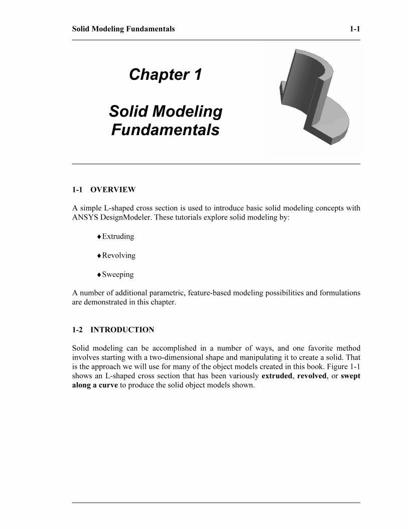
Solid Modeling Fundamentals 1-1
Chapter 1
Solid Modeling Fundamentals
1-1 OVERVIEW
A simple L-shaped cross section is used to introduce basic solid modeling concepts with
ANSYS DesignModeler. These tutorials explore solid modeling by:
♦Extruding
♦Revolving
♦Sweeping
A number of additional parametric, feature-based modeling possibilities and formulations
are demonstrated in this chapter.
1-2 INTRODUCTION
Solid modeling can be accomplished in a number of ways, and one favorite method
involves starting with a two-dimensional shape and manipulating it to create a solid. That
is the approach we will use for many of the object models created in this book. Figure 1-1
shows an L-shaped cross section that has been variously extruded, revolved, or swept
along a curve to produce the solid object models shown.
Copyrighted Material
Copyrighted
Material
Copyrighted Material
Copyrighted
Material
1-2 Solid Modeling Fundamentals
Figure 1-1 Extruding, revolving, sweeping an L-shaped section.
In the following we use this simple L-shaped section to illustrate the three fundamental
solid modeling approaches mentioned above.
1-3 TUTORIAL 1A – EXTRUSION
Follow the steps below to create a solid model of an extrusion with an L-shaped cross
section.
1. Start ANSYS Workbench
Figure 1-2 Start ANSYS Workbench in Windows.
Copyrighted Material
Copyrighted
Material
Copyrighted Material
Copyrighted
Material
Solid Modeling Fundamentals 1-3
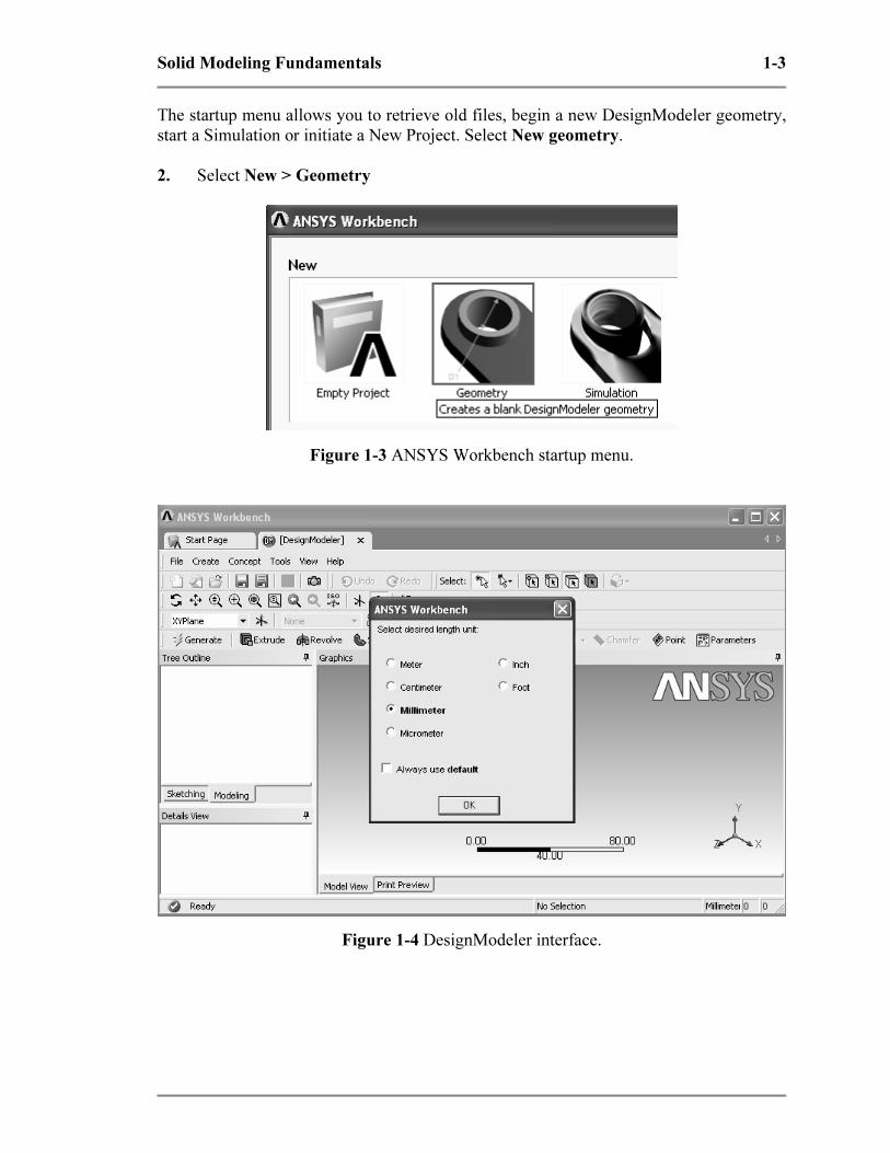
The startup menu allows you to retrieve old files, begin a new DesignModeler geometry,
start a Simulation or initiate a New Project. Select New geometry.
2. Select New > Geometry
Figure 1-3 ANSYS Workbench startup menu.
Figure 1-4 DesignModeler interface.
Copyrighted Material
Copyrighted
Material
Copyrighted Material
Copyrighted
Material
1-4 Solid Modeling Fundamentals
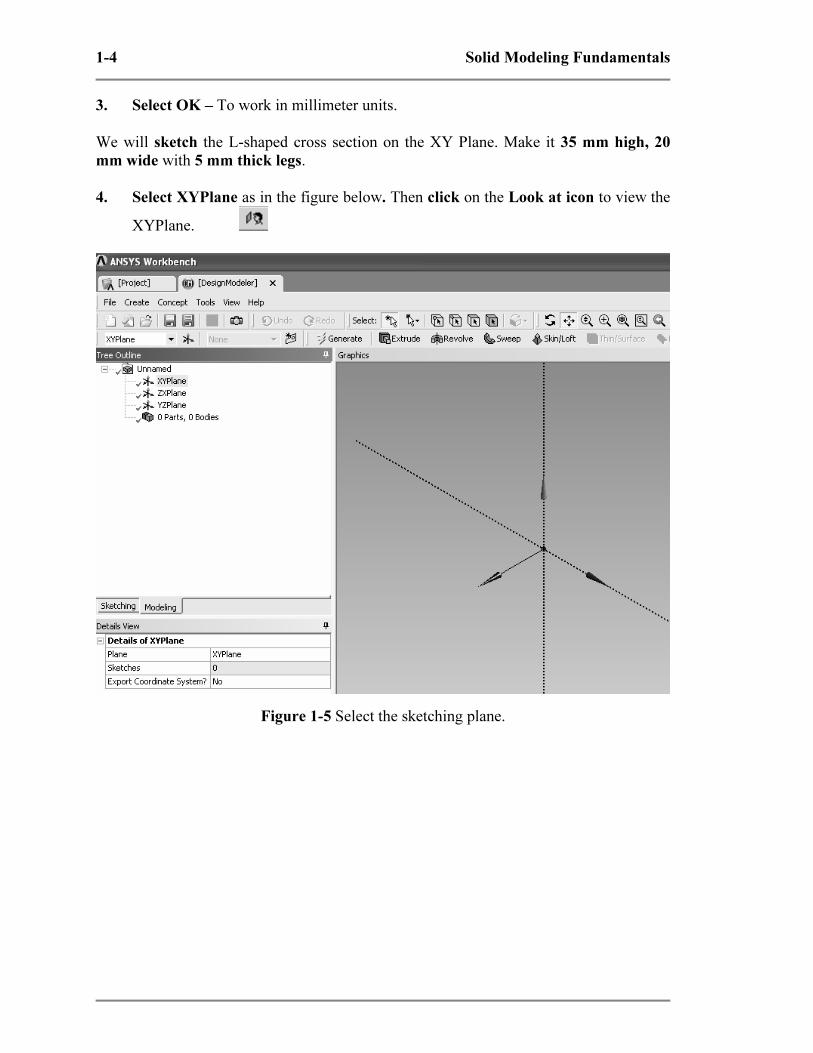
3. Select OK – To work in millimeter units.
We will sketch the L-shaped cross section on the XY Plane. Make it 35 mm high, 20
mm wide with 5 mm thick legs.
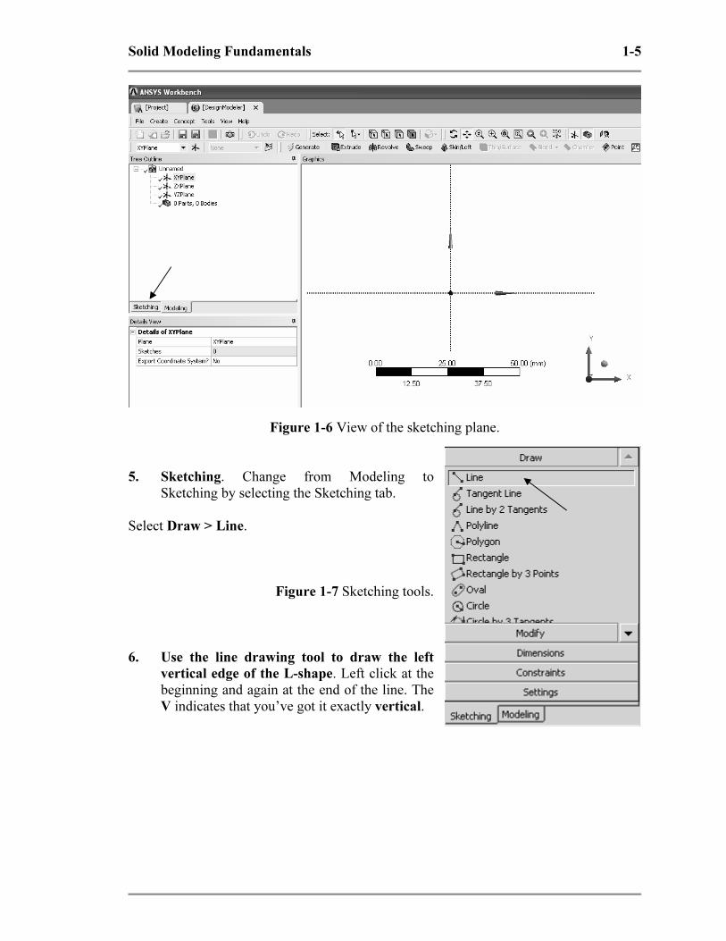
4. Select XYPlane as in the figure below. Then click on the Look at icon to view the
XYPlane.
Figure 1-5 Select the sketching plane.
Copyrighted Material
Copyrighted
Material
Copyrighted Material
Copyrighted
Material
Solid Modeling Fundamentals 1-5
Figure 1-6 View of the sketching plane.
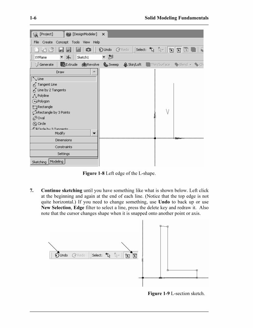
5. Sketching. Change from Modeling to
Sketching by selecting the Sketching tab.
Select Draw > Line.
Figure 1-7 Sketching tools.
6. Use the line drawing tool to draw the left
vertical edge of the L-shape. Left click at the
beginning and again at the end of the line. The
V indicates that you’ve got it exactly vertical.
Copyrighted Material
Copyrighted
Material
Copyrighted Material
Copyrighted
Material
1-6 Solid Modeling Fundamentals
Figure 1-8 Left edge of the L-shape.
7. Continue sketching until you have something like what is shown below. Left click
at the beginning and again at the end of each line. (Notice that the top edge is not
quite horizontal.) If you need to change something, use Undo to back up or use
New Selection, Edge filter to select a line, press the delete key and redraw it. Also
note that the cursor changes shape when it is snapped onto another point or axis.
Figure 1-9 L-section sketch.
Copyrighted Material
Copyrighted
Material
Copyrighted Material
Copyrighted
Material
Solid Modeling Fundamentals 1-7
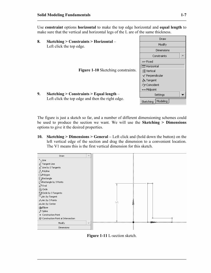
Use constraint options horizontal to make the top edge horizontal and equal length to
make sure that the vertical and horizontal legs of the L are of the same thickness.
8. Sketching > Constraints > Horizontal –
Left click the top edge.
Figure 1-10 Sketching constraints.
9. Sketching > Constraints > Equal length –
Left click the top edge and then the right edge.
The figure is just a sketch so far, and a number of different dimensioning schemes could
be used to produce the section we want. We will use the Sketching > Dimensions
options to give it the desired properties.
10. Sketching > Dimensions > General – Left click and (hold down the button) on the
left vertical edge of the section and drag the dimension to a convenient location.
The V1 means this is the first vertical dimension for this sketch.
Figure 1-11 L-section sketch.

Copyrighted Material
Copyrighted
Material
Copyrighted Material
Copyrighted
Material
1-8 Solid Modeling Fundamentals
Continue with general dimensioning to specify H2 and V4. Don’t dimension the top
edge; it has to be equal to V4. The bottom edge is located directly on the X axis but we
need to locate the vertical edge with respect to the Y axis.
11. Sketching > Dimensions > Horizontal – Left click the left vertical edge then click
the dotted Y axis and drag the H3 dimension to a convenient location.
Figure 1-12 L-section sketch with all dimensions.
The current values for the dimensions depend upon the scale used in the sketching
process, e.g., H2 = 20.012 mm in the Details of Sketch1 box shown in the figure above.
12. Edit the dimensions to give them the desired
values. – Click on a value, enter the change and
press return.
Figure 1-13 Default dimension values.

Copyrighted Material
Copyrighted
Material
Copyrighted Material
Copyrighted
Material
Solid Modeling Fundamentals 1-9
13. View > Ruler (Top menu) to turn off the ruler display. Use the middle mouse roller
to zoom in and out.
To reposition the section on the screen, right click in the graphics area of the display and
select one of the following options: Cursor Mode, View, or Zoom to Fit.
The result is shown in the figure below.
Figure 1-14 Edited dimension values.
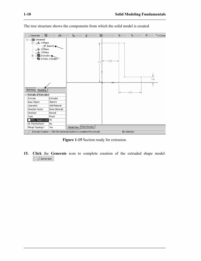
To perform the extrusion, switch back from Sketching to Modeling. If it is not already
highlighted, click Sketch1 in the Tree Outline to highlight it.
14. Modeling > Sketch1 > Extrude
The L-shaped section will be extruded along the positive Z axis by the amount specified
in the Depth field shown in the Details of Extrude1 box (next figure). Edit this value
(45 mm) to give the solid an extrude depth of 100 mm.
Copyrighted Material
Copyrighted
Material
Copyrighted Material
Copyrighted
Material
1-10 Solid Modeling Fundamentals
The tree structure shows the components from which the solid model is created.
Figure 1-15 Section ready for extrusion.
15. Click the Generate icon to complete creation of the extruded shape model.
Copyrighted Material
Copyrighted
Material
Copyrighted Material
Copyrighted
Material
Solid Modeling Fundamentals 1-11
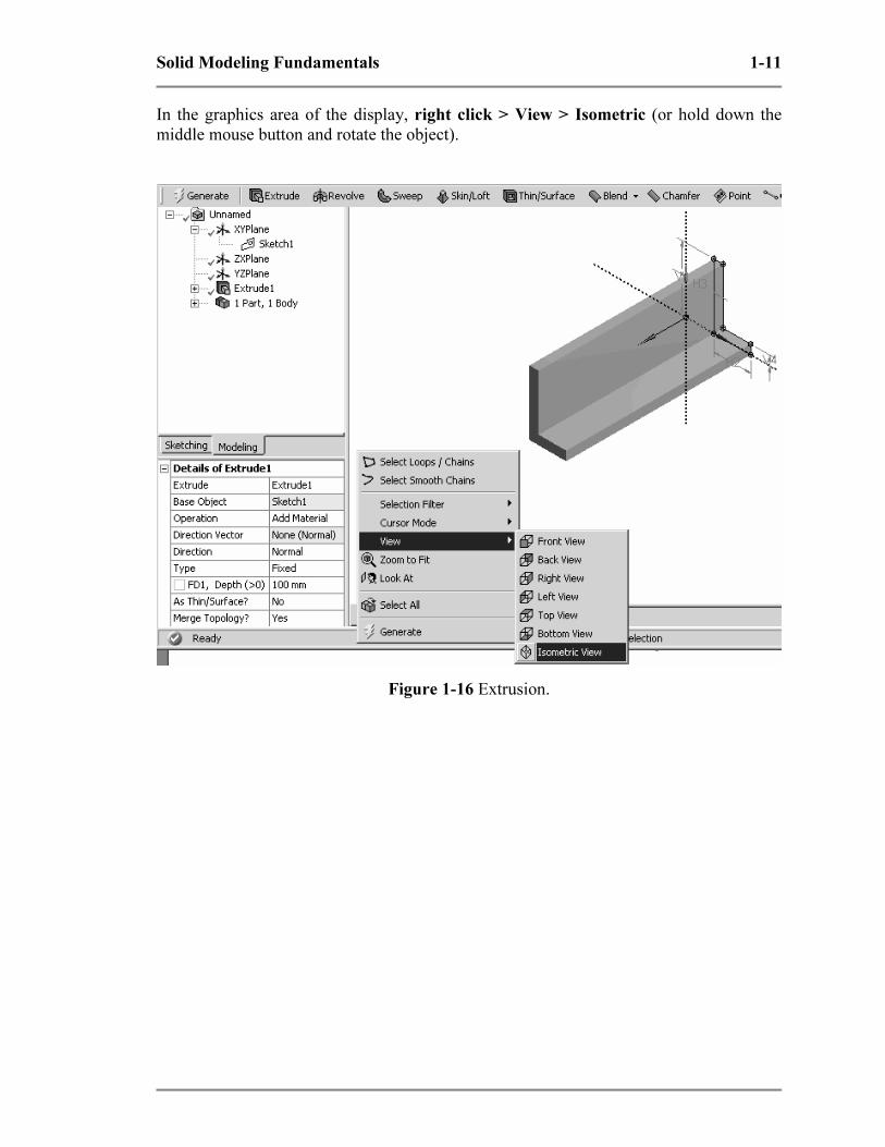
In the graphics area of the display, right click > View > Isometric (or hold down the
middle mouse button and rotate the object).
Figure 1-16 Extrusion.
Copyrighted Material
Copyrighted
Material
Copyrighted Material
Copyrighted
Material
1-12 Solid Modeling Fundamentals
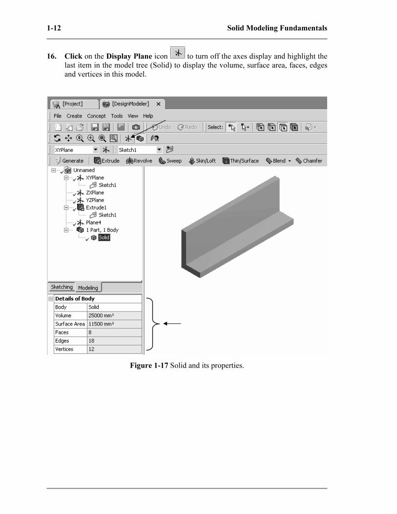
16. Click on the Display Plane icon to turn off the axes display and highlight the
last item in the model tree (Solid) to display the volume, surface area, faces, edges
and vertices in this model.
Figure 1-17 Solid and its properties.

Copyrighted Material
Copyrighted
Material
Copyrighted Material
Copyrighted
Material
Solid Modeling Fundamentals 1-13
17. Save your work – Use the Save As option to save the extrusion using a name (e.g.
T1A) and location of your choice.
Figure 1-18 File menu.
Basic solid modeling notions have been used thus far to demonstrate creating a solid by
extruding a two-dimensional section. In the next tutorial we will revolve the same L-
shape to create a solid of revolution.
1-4 TUTORIAL 1B – REVOLUTION
We can reuse the extrusion model after it has been safely saved somewhere. Start from
the screen shown below if the extrusion is still in memory, or start Workbench and reload
the extrusion.
First modify the tree structure.
Copyrighted Material
Copyrighted
Material
Copyrighted Material
Copyrighted
Material
1-14 Solid Modeling Fundamentals
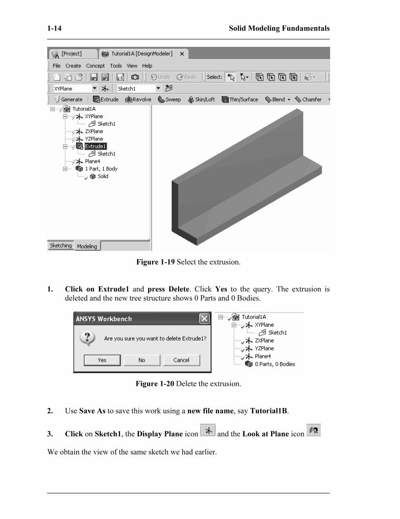
Figure 1-19 Select the extrusion.
1. Click on Extrude1 and press Delete. Click Yes to the query. The extrusion is
deleted and the new tree structure shows 0 Parts and 0 Bodies.
Figure 1-20 Delete the extrusion.
2. Use Save As to save this work using a new file name, say Tutorial1B.
3. Click on Sketch1, the Display Plane icon and the Look at Plane icon
We obtain the view of the same sketch we had earlier.

Copyrighted Material
Copyrighted
Material
Copyrighted Material
Copyrighted
Material
Solid Modeling Fundamentals 1-15
Figure 1-21 Select the sketch.
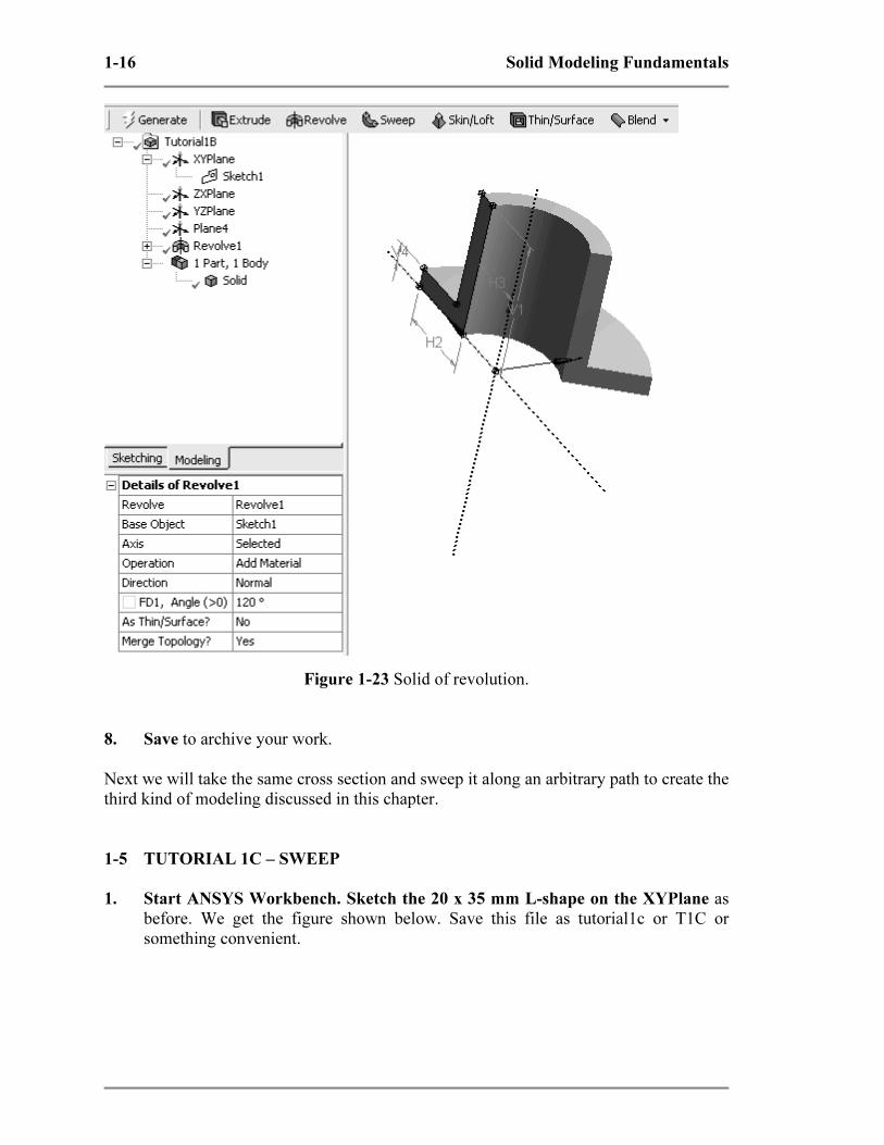
4. Be sure Sketch1 is highlighted and click
Revolve.
5. Click Axis > Select the Y axis > Apply
in Details of Revolve1 box (below right).
6. Select Angle > Enter 120 deg.
7. Click Generate
The L-shaped section is rotated about the Y axis by
120 degrees to create the solid of revolution shown
next. Direction options change the rotation direction.
Figure 1-22 Revolve1 tree.
Copyrighted Material
Copyrighted
Material
Copyrighted Material
Copyrighted
Material
1-16 Solid Modeling Fundamentals
Figure 1-23 Solid of revolution.
8. Save to archive your work.
Next we will take the same cross section and sweep it along an arbitrary path to create the
third kind of modeling discussed in this chapter.
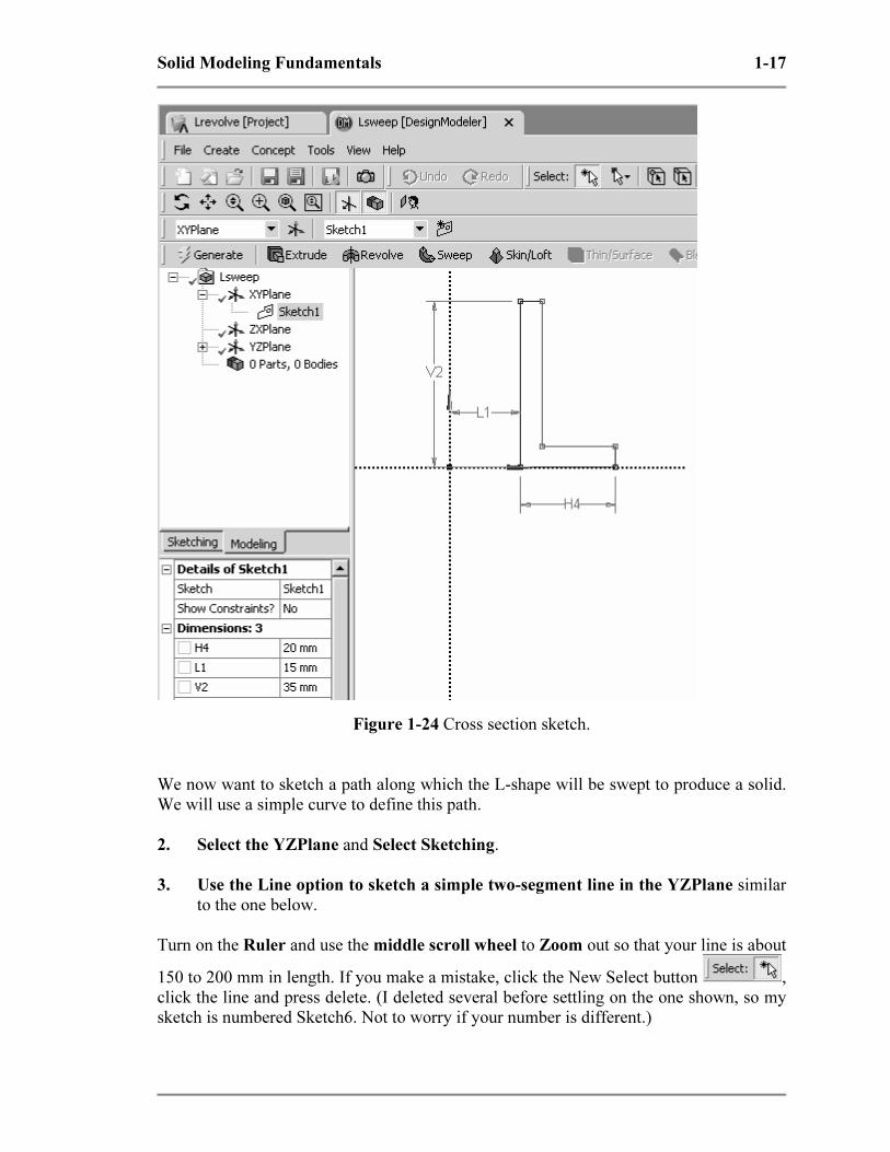
1-5 TUTORIAL 1C – SWEEP
1. Start ANSYS Workbench. Sketch the 20 x 35 mm L-shape on the XYPlane as
before. We get the figure shown below. Save this file as tutorial1c or T1C or
something convenient.
Copyrighted Material
Copyrighted
Material
Copyrighted Material
Copyrighted
Material
Solid Modeling Fundamentals 1-17
Figure 1-24 Cross section sketch.
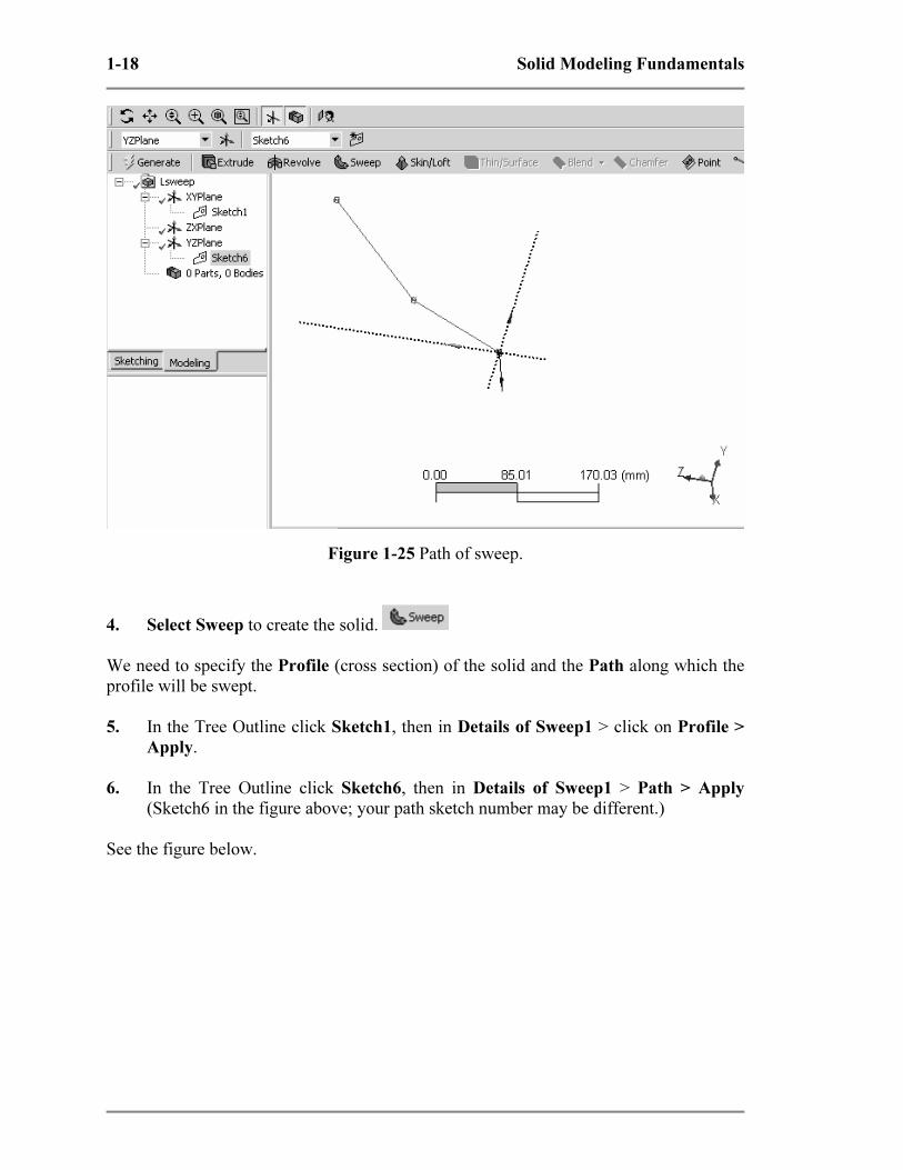
We now want to sketch a path along which the L-shape will be swept to produce a solid.
We will use a simple curve to define this path.
2. Select the YZPlane and Select Sketching.
3. Use the Line option to sketch a simple two-segment line in the YZPlane similar
to the one below.
Turn on the Ruler and use the middle scroll wheel to Zoom out so that your line is about
150 to 200 mm in length. If you make a mistake, click the New Select button ,
click the line and press delete. (I deleted several before settling on the one shown, so my
sketch is numbered Sketch6. Not to worry if your number is different.)
Copyrighted Material
Copyrighted
Material
Copyrighted Material
Copyrighted
Material
1-18 Solid Modeling Fundamentals
Figure 1-25 Path of sweep.
4. Select Sweep to create the solid.
We need to specify the Profile (cross section) of the solid and the Path along which the
profile will be swept.
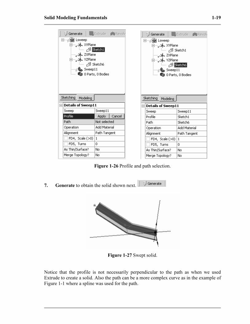
5. In the Tree Outline click Sketch1, then in Details of Sweep1 > click on Profile >
Apply.
6. In the Tree Outline click Sketch6, then in Details of Sweep1 > Path > Apply
(Sketch6 in the figure above; your path sketch number may be different.)
See the figure below.
Copyrighted Material
Copyrighted
Material
Copyrighted Material
Copyrighted
Material
Solid Modeling Fundamentals 1-19
Figure 1-26 Profile and path selection.
7. Generate to obtain the solid shown next.
Figure 1-27 Swept solid.
Notice that the profile is not necessarily perpendicular to the path as when we used
Extrude to create a solid. Also the path can be a more complex curve as in the example of
Figure 1-1 where a spline was used for the path.
Copyrighted Material
Copyrighted
Material
Copyrighted Material
Copyrighted
Material
1-20 Solid Modeling Fundamentals
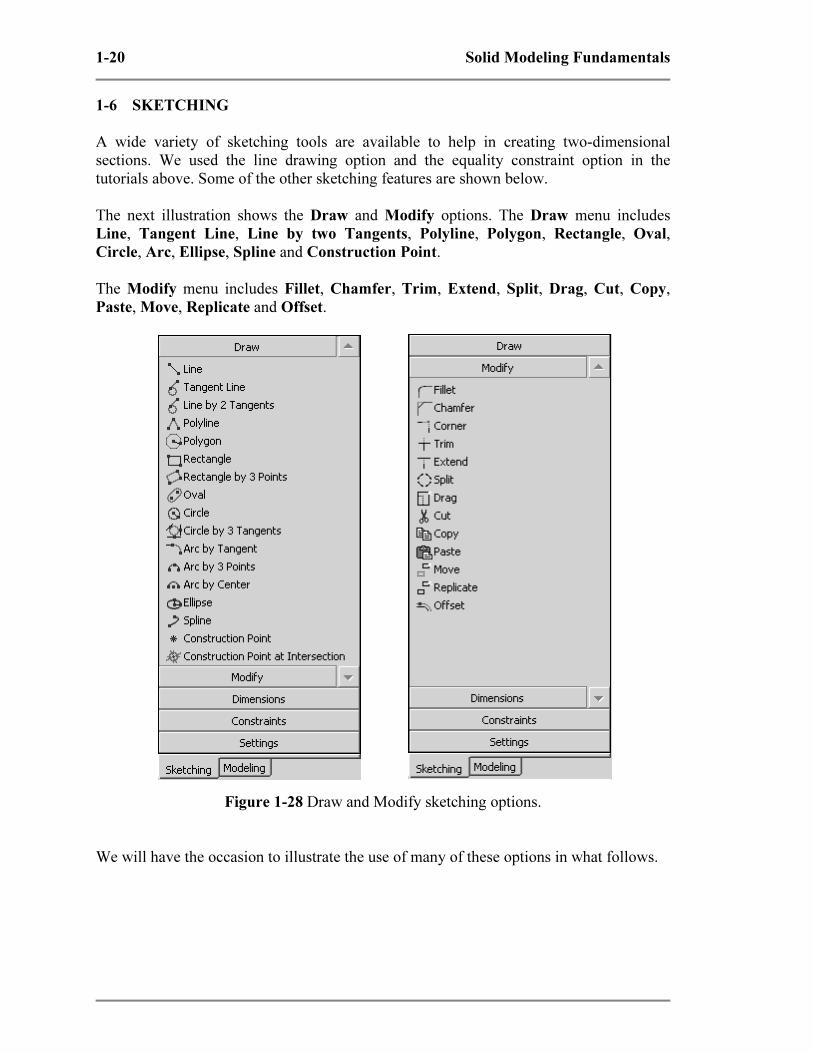
1-6 SKETCHING
A wide variety of sketching tools are available to help in creating two-dimensional
sections. We used the line drawing option and the equality constraint option in the
tutorials above. Some of the other sketching features are shown below.
The next illustration shows the Draw and Modify options. The Draw menu includes
Line, Tangent Line, Line by two Tangents, Polyline, Polygon, Rectangle, Oval,
Circle, Arc, Ellipse, Spline and Construction Point.
The Modify menu includes Fillet, Chamfer, Trim, Extend, Split, Drag, Cut, Copy,
Paste, Move, Replicate and Offset.
Figure 1-28 Draw and Modify sketching options.
We will have the occasion to illustrate the use of many of these options in what follows.
Copyrighted Material
Copyrighted
Material
Copyrighted Material
Copyrighted
Material
Solid Modeling Fundamentals 1-21
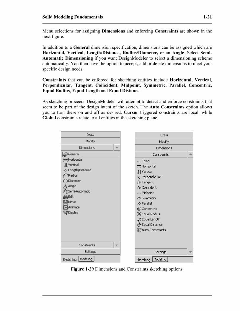
Menu selections for assigning Dimensions and enforcing Constraints are shown in the
next figure.
In addition to a General dimension specification, dimensions can be assigned which are
Horizontal, Vertical, Length/Distance, Radius/Diameter, or an Angle. Select Semi-
Automatic Dimensioning if you want DesignModeler to select a dimensioning scheme
automatically. You then have the option to accept, add or delete dimensions to meet your
specific design needs.
Constraints that can be enforced for sketching entities include Horizontal, Vertical,
Perpendicular, Tangent, Coincident, Midpoint, Symmetric, Parallel, Concentric,
Equal Radius, Equal Length and Equal Distance.
As sketching proceeds DesignModeler will attempt to detect and enforce constraints that
seem to be part of the design intent of the sketch. The Auto Constraints option allows
you to turn these on and off as desired. Cursor triggered constraints are local, while
Global constraints relate to all entities in the sketching plane.
Figure 1-29 Dimensions and Constraints sketching options.
Copyrighted Material
Copyrighted
Material
Copyrighted Material
Copyrighted
Material
1-22 Solid Modeling Fundamentals
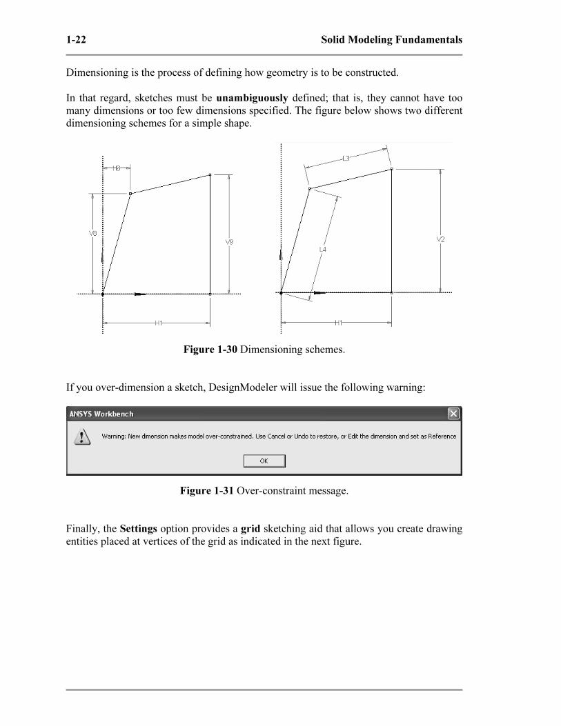
Dimensioning is the process of defining how geometry is to be constructed.
In that regard, sketches must be unambiguously defined; that is, they cannot have too
many dimensions or too few dimensions specified. The figure below shows two different
dimensioning schemes for a simple shape.
Figure 1-30 Dimensioning schemes.
If you over-dimension a sketch, DesignModeler will issue the following warning:
Figure 1-31 Over-constraint message.
Finally, the Settings option provides a grid sketching aid that allows you create drawing
entities placed at vertices of the grid as indicated in the next figure.

Copyrighted Material
Copyrighted
Material
Copyrighted Material
Copyrighted
Material
Solid Modeling Fundamentals 1-23
Figure 1-32 Settings options and a sketching grid.
1-7 SUMMARY
Three tutorials in Chapter 1 introduce basic solid model creation in ANSYS
DesignModeler and provide examples from which more complex shapes can be
developed. In the next chapter we will extend these ideas and introduce additional
modeling features.
1-8 PROBLEMS
1-1 Identify some common objects (such as an unsharpened pencil, drinking glass, etc.)
and develop models of them using the ideas presented in this chapter.
1-2 Use a “Z” shaped section to create a solid by extrusion, another by revolving, and
another by sweeping. Select your own units and dimensions.
1-3 Measure the exterior dimensions of a light bulb, estimate the wall thickness of the
glass and base, and create a model by revolving the sketch.
1-4 Create the shape shown and extrude it to form a solid. Choose your own
dimensions. Use the Sketching Trim option to help in the sketch development.
Save it and we’ll use it in a simulation problem later in the text.
Figure P1-4