Embed Size (px)
Citation preview

ANSI C29.2-1992 (R1999)
American National Standard
for Insulators-
Wet-Process Porcelain and Toughened Glass-
Suspension Type
http//:www.wangd.com
ANSI C29.2-1992 (RI 999)
Amer i ca n Nat i on a I Stand a rd for Insulators-
Wet-Process Porcelain and Toughened Glass-
Suspension Type
Secretariat
National Electrical Manufacturers Association
Approved December 8, 1999
American National Standards Institute, Inc.
http//:www.wangd.com

STD-NEMA CZ9.2-ENGL 19T2 6470247 0524115 7T8
ANSI C29.2-1992 (R1999)
American National Standard
Approval of an American National Standard requires verification by ANSI that the requirements for due process, consensus, and other criteria for approval have been met by the standards developer.
Consensus is established when, in the judgment of the ANSI Board of Standards Review, substantial agreement has been reached by directly and materially affected interests. Substantial agreement means much more than a simple majority, but not necessarily unanimity. Consensus requires that all views and objections be considered, and that a concerted effort be made toward their resolution.
The use of American National Standards is completely voluntary; their existence does not in any respect preclude anyone, whether he has approved the standards or not, from manufacturing, marketing, purchasing, or using products, processes, or procedures not conforming to the standards.
The American National Standards Institute does not develop standards and will in no circumstances give an interpretation of any American National Standard. Moreover, no person shall have the right or authority to issue an interpretation of an American National Standard in the name of the American National Standards Institute. Requests for interpretations shall be addressed to the secretariat or sponsor whose name appears on the title page of this standard.
CAUTION NOTICE: This American National Standard may be revised or withdrawn at any time. The procedures of the American National Standards Institute require that action be taken to reaffirm, revise, or withdraw this standard no later than five years from the date of approval. Purchasers of American National Standards may receive current information on all standards by calling or writing the American National Standards Institute.
Published by
National Electrical Manufacturers Association 1300 N. 17th Street, Rosslyn, Virginia 22209
Copyright O 2000 National Electrical Manufacturers Association Ali rights reserved.
No part of this publication may be reproduced in any form, in an electronic retrieval system or otherwise, without prior written permission of the publisher.
Printed in the United States of America
http//:www.wangd.com

~ ~ _ _ _ _ _ ~~~ ~ ~ ~~ ~ ~ _ _ _ _ _ ~ _ _ _ _ _ ~ ~
S T D - N E M A C29-2-ENGL 3992 M 6430247 0524336 634 D
ANSI C29.2-1992 (Rl999)
Contents Page
Foreword ....................................................................................................................................................... III 1 Scope .................................................................................................................................................... 1 2 Normative references ............................................................................................................................ 1 3 Definitions .............................................................................................................................................. 1 4 General .................................................................................................................................................. 2 5 Material .................................................................................................................................................. 2
5.1 Insulator shells ............................................................................................................................... 2 5.2 Shell surface ................................................................................................................................... 2 5.3 Metal parts ...................................................................................................................................... 3 5.4 Cotter keys ..................................................................................................................................... 3
5.4.1 Material ................................................................................................................................... 3 5.4.2 Ball-and-socket insulators ....................................................................................................... 3 5.4.3 Clevis insulators ...................................................................................................................... 3 Dimensions and characteristics ............................................................................................................. 3
Sampling, inspection, and tests ............................................................................................................. 4 8.1 General ........................................................................................................................................... 4 8.2 Design tests .................................................................................................................................... 4 8.2.1 Low-frequency dry flashover test ................................................................................................ 4 8.2.2 Low-frequency wet flashover test ............................................................................................... 4 8.2.3 Critical impulse flashover tests-positive and negative .............................................................. 4 8.2.4 Radio-influence voltage test ....................................................................................................... 4 8.2.5 Thermal-mechanical load cycle test ........................................................................................... 4 8.2.6 Thermal shock test ..................................................................................................................... 5 8.2.7 Residual-strength test ................................................................................................................. 5 8.2.8 Impact test .................................................................................................................................. 5 8.2.9 Cotter key test ............................................................................................................................. 6 8.2.1 O Cement expansion ...................................................................................................................... 6 8.3 Quality conformance tests ........................................ .............................................................. 6
8.3.1 Visual and dimensional tests ................................................................................................... 6 8.3.2 Porosity test ............................................................................................................................ 6 8.3.3 Galvanizing test ....................................................................................................................... 6 8.3.4 Combined mechanical and electrical-strength tests ............................................................... 7 8.3.5 Puncture tests ......................................................................................................................... 7
8.4 Routine tests .................................................................................................................................. 8 8.4.1 Cold-to-hot thermal shock test ................................................................................................ 8 8.4.2 Hot-to-cold thermal shock test ................................................................................................ 8 8.4.3 Tension proof test ................................................................................................................... 8 8.4.4 Flashover test .......................................................................................................................... 8
Table 4 - Dimensions and characteristics of clevis transmission insulators .......................................... 11 (ANSI classes 52-4, 52-6, 52-10, 52-12) ................................................................................................. 11 Figure 3 - Clevis suspension insulator classes 524, 52-6, 52-10, and 52-12 ........................................ 14 Figure 4 - Ball gauge for class 52-3 insulator ......................................................................................... 15
Figure 6 - Ball gauge for class 52-5 insulator ....................................................................................... 17 Figure 7 - Ball gauge for class 52-8 and 52-1 1 insulators ...................................................................... 18
Figure 9 - Schematic representation of thermal-mechanical performance test ..................................... 20
...
6
8 7 Marking .................................................................................................................................................. 3
Table 2 - Dimensions and characteristics of distribution .......................................................................... 9
Figure 5 - Socket gauge for class 52-3 and 52-5 insulator .................................................................... 16
Figure 8 - Socket gauge for class 52-8 and 52-1 1 insulators ................................................................. 19
Figure 10 - Impact testing machine ........................................................................................................ 21 Annex A ...................................................................................................................................................... 23
Packaging ............................................................................................................................................... 23 Annex B ................................................................................................................................................... 25 Bibliography ............................................................................................................................................. 25
http//:www.wangd.com

S T D D N E M A C29-Z-ENGL L992 b470247 0524117 570
ANSI C29.2-1992 (R1999)
Foreword (This Foreword is not a part of American National Standards C29.2-1992 (R1999).)
This standard has its origins in one of a series of Standards issued in 1952 by the Joint Committee on Insulator Standards of the Edison Electric Institute and the National Electrical Manufacturers Association.
That original 1952 standard was designated as: EEI-NEMA Standards for Wet-Process Porcelain Insulators (Suspension Type), EEI Publication Number TDJ-52, NEMA Publication Number 140-1 952.
Several subsequent revisions were made and issued by the American Standards Association, Incorporated, and more recently by the American National Standards Institute (ANSI), as an American National Standard.
This standard is periodically reviewed for any revisions necessary to keep it current with advancing technology. Suggestions for improvement of this standard are welcome. They should*be sent to: Vice President, Engineering, National Electrical Manufacturer's Association, 1300 North 17 Street, Suite 1847, Rosslyn, VA 22209
This standard was processed and approved for submittal to ANSI by ASC C29. Committee approval of the standard does not necessarily imply that all committee members voted for approval. At the time ANSI approved this standard, the ASC Committee had the following members:
R. Harmon, Chair J. Vamer, Vice Chair K. Masri, Secretary
Organization Represented Name of Representative
Edison Electric Institute & Electric Light and Power Group. A. S. Jagtiani J. Vamer R. Candaran (Alt.) N. J. DeSantis J. Karcher D.H. Shaffner W.D. Sneal G.C. Royster (Alt.)
R. Harmon E. Gnandt T. Girsham R. Sundararajan
G. A. Stewart R. A. Bemstorí R. Gemignani (Alt.) R. Hill A. Baker F. Richens G. Powell (Alt.) R. Stanley J. M. George C. de Tourreil (Alt.) J. Yu
Institute of Electrical & Electronic Engineers ....................... T. A. Pinkham
National Electrical Manufacturers Association .................... A. Schwalm
U. S. Department of the Army (Liaison without Vote) .......... Vacant U. S. Department of Energy ................................................. Vacant Individuals ............................................................................ J. Buchanan
. . . . 111
Previous page is blank.
http//:www.wangd.com

~~~
S T D - N E M A C27.2-ENGL 1992 h470247 0524118 407 E
AMERICAN NATIONAL STANDARD ANSI C29.2-I992 (R I9991
1 Scope
This standard covers suspension-type insulators, 4-114 inches (1 08 millimeters) in diameter and larger, made of wet-process porcelain or of toughened glass and used in the transmission and distribution of electrical energy.
2 Normative references
This standard is intended to be used in conjunction with the following American National Standards. When the referenced standards are superseded by a revision approved by the American National Standards Institute Inc., the revision shall apply.
ANSI C29.1-I 988, Test Methods of Electrical Power Insulators
ANSI 255.1-1 967 (R1973), Gray Finishes for Industrial Apparatus and Equipment'
ANSVIEEE 268-1 982, Metric Practice
ASTM A l 53-82, Specification for Zinc Coating (Hot-Dip) on Iron and Steel Hardware'
ASTM C l 51-84, Test Method for Autoclave Expansion of Portland Cement
3 Definitions
See section 2 of American National Standard Test Methods for Electrical Power Insulators, ANSI C29.1-1988, for definitions of terms.
This standard has been withdrawn but is still available in archive form. Contact ANSI's Sales Department. 1
* Available from ASTM, 1916 Race Street, Philadelphia, PA 19103.
I
http//:www.wangd.com
STD.NEMA C29-2-ENGL 1177Z m 6470247 0524LLq 343 ANSI C29.2-1992 (RI%@)
4 General
4.1 and figures supplement each other and shall be considered part of this standard.
Insulators shall conform in all respects to the requirements of this standard. The text
4.2 with all pertinent dimensions. Any variations in these dimensions due to manufacturing tolerances shall be indicated.
Manufacturer's drawings, if furnished, shall show the outline of the insulators, together
5 Material
5.1 Insulator shells
The insulator shells shall be made of wet-process porcelain or toughened glass. Shells shall be sound and free from defects that might adversely affect the insulators.
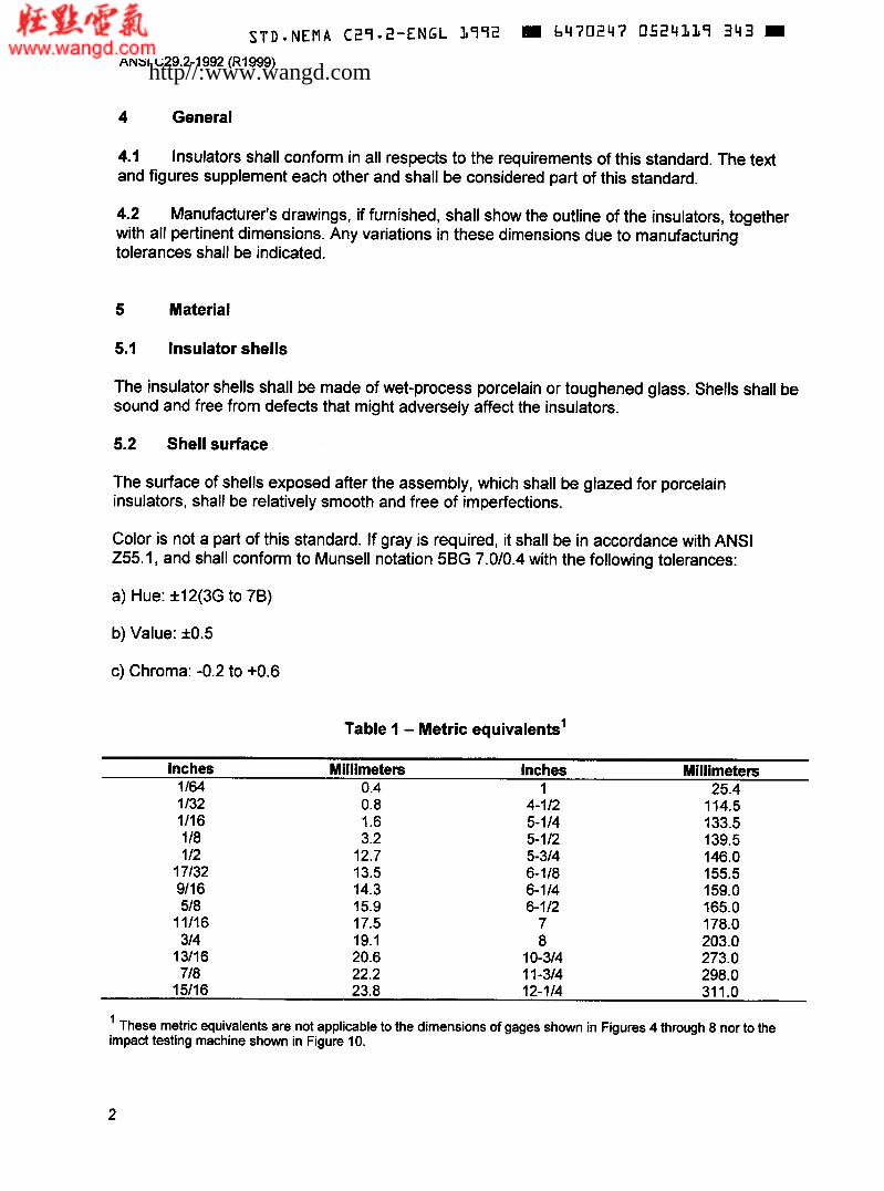
5.2 Shell surface
The surface of shells exposed after the assembly, which shall be glazed for porcelain insulators, shall be relatively smooth and free of imperfections.
Color is not a part of this standard. If gray is required, it shall be in accordance with ANSI Z55.1, and shall conform to Munsell notation 5BG 7.010.4 with the following tolerances:
a) Hue: 112(3G to 78)
b) Value: 10.5
c) Chroma: -0.2 to +0.6
Table 1 - Metric equivalents'
Inches Millimeters Inches Millimeters 1 164 0.4 1 25.4 1/32 1/16 1 I8 1 12
17/32 911 6 518
11/16 314
13/16 718
0.8 1.6 3.2
12.7 13.5 14.3 15.9 17.5 19.1 20.6 22.2
4-112 5-114 5-1 12 5-314 6-118 6-1 14 6-1 I2
7 8
10-314 1 1-314
114.5 133.5 139.5 146.0 155.5 159.0 165.0 178.0 203.0 273.0 298.0
15/16 23.8 12-114 311.0
' These metric equivalents are not applicable to the dimensions of gages shown in Figures 4 through 8 nor to the impact testing machine shown in Figure IO.
2
http//:www.wangd.com
~~ ~ _ _ _
STD.NEMA C29-2-ENGL 3992 bp70247 0524320 Ob5
ANSI C29.2-1992 (R1999)
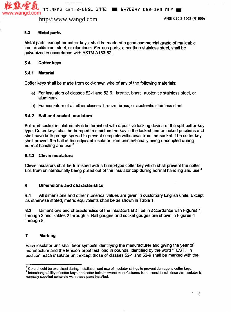
5.3 Metal parts
Metal parts, except for cotter keys, shall be made of a good commercial grade of malleable iron, ductile iron, steel, or aluminum. Ferrous parts, other than stainless steel, shall be galvanized in accordance with ASTM A I 53-82.
5.4 Cotter keys
5.4.1 Material
Cotter keys shall be made from cold-drawn wire of any of the following materials:
a) For insulators of classes 52-1 and 52-9: bronze, brass, austenitic stainless steel, or aluminum.
b) For insulators of all other classes: bronze, brass, or austenitic stainless steel.
5.4.2 Ball-and-socket insulators
Ball-and-socket insulators shall be furnished with a positive locking device of the split cotter-key type. Cotter keys shall be humped to maintain the key in the locked and unlocked positions and shall have both prongs spread to prevent complete withdrawal from the socket. The cotter key shall prevent the ball of the adjacent insulator from unintentionally being uncoupled during normal handling and use.3
5.4.3 Clevis insulators
Clevis insulators shall be furnished with a hump-type cotter key which shall prevent the cotter bolt from unintentionally being pulled out of the insulator cap during normal handling and
6 Dimensions and characteristics
6.1 as othewise stated, metric equivalents shall be as shown in Table 1.
All dimensions and other numerical values are given in customary English units. Except
6.2 through 3 and Tables 2 through 4. Ball gauges and socket gauges are shown in Figures 4 through 8.
Dimensions and characteristics of the insulators shall be in accordance with Figures I
7 Marking
Each insulator unit shall bear symbols identifying the manufacturer and giving the year of manufacture and the tension-proof test load in pounds, identified by the word "TEST." In addition, each insulator unit except those of classes 52-1 and 52-9 shall be marked with the
Care should be exercised during installation and use of insulator strings to prevent damage to cotter keys. Interchangeability of cotter keys and cotter bolts between manufacturers is not considered, since the insulator is 4
normally supplied complete with these parts installed.
http//:www.wangd.com

STD*NEMA C29-2 -ENGL 1992 II b470247 0524323 TTL
ANSI C29.2-1992 (R1999)
combined mechanical and electrical rating in pounds identified by the symbol "M&E." The markings shall be legible and durable.
8 Sampling, inspection, and tests
8.1 General
Tests described in 8.2 shall be required only on insulators of new design. Tests described in 8.3 shall be required on each lot of insulators. Tests described in 8.4 shall be made on each insulator.
8.2 Design tests
8.2.1 Low-frequency dry flashover test
Three insulators shall be selected at random and tested in accordance with 4.2 of ANSI C29.1. Failure of the average dry flashover value of the three insulators to equal or exceed 95 percent of the rated dry flashover value, as given in the applicable table, shall constitute failure to meet the requirements of this standard.
8.2.2 Low-frequency wet flashover test
Three insulators shall be selected at random and tested in accordance with 4.3 of ANSI C29.1, except that for distribution insulators normally used in a horizontal position, the mounting arrangement may be similar to service orientation. Failure of the average wet flashover value of the three insulators to equal or exceed 90 percent of the rated wet flashover value, as given in the applicable table, shall constitute failure to meet the requirements of this standard.
8.2.3 Critical impulse flashover tests-positive and negative
Three insulators shall be selected at random for the critical impulse flashover test, positive, and three for the critical impulse flashover test, negative, and tested in accordance with 4.7 of ANSI C29.1. Failure of the average critical impulse flashover value of the three insulators to equal or exceed 92 percent of the rated critical impulse flashover value, as given in the applicable table, shall constitute failure to meet the requirements of this standard.
8.2.4 Radio-influence voltage test
Three insulators shall be selected at random and tested in accordance with 4.9 of ANSI C29.1. If one or more insulators fail to meet the requirements as given in the applicable table, three additional insulators shall be selected at random and tested. Failure or one or more of these additional insulators shall constitute failure to meet the requirements of this standard.
8.2.5 Thermal-mechanical load cycle test
Ten assembled insulators shall be selected at random and subjected to the thermal-mechanical load cycle test. The insulators, which may be connected in series or parallel provided each is equally loaded, shall be subjected to four 24 hour cycles of ambient air cooling and heating with a simultaneously applied minimum tensile load maintained at 60 percent of the rated combined
4
http//:www.wangd.com

STD-NEMA C29.2-ENGL 1972 M 6470247 0524322 938
ANSI C29.2-1992 (RI999)
mechanical and electrical strength of the insulators as described in Figure 9. Each 24 hour cycle shall start with a cooling period during which a low temperature of -22°F (-30°C) shall be maintained for at least a four hour period. A heating period will follow the cooling period. During the heating period a high temperature of 104°F (40 C) shall be maintained for at least a four hour period.
During the four hour extreme temperature periods, the ambient air temperature shall be maintained at the specified extreme temperature within 9OF (5OC). The rate of temperature change is not specified. The tensile load shall be applied at room temperature before starting the first thermal cycle. The tensile load shall be completely removed and reapplied after the first, second, and third 24 hour thermal cycle. After the fourth thermal cycle, upon cooling to room temperature, the tensile load shall be removed. The ten insulators shall then be subjected to a Combined Mechanical and Electrical Test in accordance with 5.2 of ANSI C29.1 The criteria for determining conformance with the standard are as given in 8.3.4.
8.2.6 Thermal shock test
Five insulators shall be selected at random and tested for ten complete cycles in accordance with 5.5 of ANSI C29.1. The temperature of the hot water bath shall be approximately 205°F (9SoC), and the temperature of the cold water bath shall be approximately 39°F (4°C). If one or more insulators fail, five additional insulators shall be selected at random and tested. Failure of one or more of these additional insulators shall constitute failure to meet the requirements of this standard.
8.2.7 Residual-strength test
Twenty-five assembled units shall be selected at random and have the shells broken off. No portion of the shell shall remain outside the maximum diameter of the cap. Each assembly shall then be subjected to a mechanical-strength test in accordance with 5.1 of ANSI C29.1. The criteria for determining conformance to this standard are:
OR 2 (1.2 xtension-proof load) + 1.645%
Where:
OR = average residual strength of 25 units
SR = standard deviation of residual strength of the 25 units tested.
8.2.8 Impact test
Three assembled insulators shall be selected at random and tested in accordance with 5.1.2.2 of ANSI C29.1. The test specimen shall be mounted in the test machine shown in Figure I O . If one or more insulators fail to meet the requirements given in the applicable table, three additional assembled insulators shall be selected at random and tested. Failure of one or more of the additional insulators shall constitute failure to meet the requirements of this standard.
5
http//:www.wangd.com

STD-NEMA C29-2-ENGL L992 E b470247 05241i23 874 H
ANSI C29.2-1992 (R1999)
8.2.9 Cotter key test
For three test samples of ball-and-socket insulators, the disengagement force of the cotter key shall be between 25 and 150 pounds (1 11 and 667 newtons) force for three locking-to- unlocking operations.
8.2.10 Cement expansion
If Portland cement is used in the assembly of the insulators, it shall have an autoclave expansion limit of less than 0.12 percent when tested in accordance with ASTM C151-84, Test Method for Autoclave Expansion of Portland Cement.
8.3 Quality conformance tests5
8.3.1 Visual and dimensional tests
Conformity with 5.2 of this standard may be determined by visual inspection. All insulators not conforming to 5.2 fail to meet the requirements of this standard.
Three insulators shall be selected at random from the lot and their dimensions checked against the dimensions on the manufacturer’s drawing. Failure of more than one of these insulators to conform, within manufacturing tolerances, to the dimensions on this drawing shall constitute failure of the lot to meet the requirements of this standard.
8.3.2 Porosity test
Specimens shall be selected from porcelain insulators destroyed in other tests and tested in accordance with 5.4 of ANSI C29.1. Penetration of the dye into the body of the dielectric shall constitute failure of the lot to meet the requirements of this standard.
8.3.3 Galvanizing test
Five pieces representative of each type of galvanized hardware used with the insulators shall be selected at random and tested in accordance with Section 6 of ANSI C29.1. Five to ten measurements shall be randomly distributed over the entire surface. Both the average thickness value for each individual specimen and the average of the entire sample shall equal or exceed the following:
Average of Individual Average of Entire Sample Specimen
Hardware(except nuts/boits) 3.4 mil 3.1 mil Nuts/bolts 2.1 mil 1.7 mil
If the average of one specimen, or if the average of the entire sample, fails to comply with the table above, ten additional pieces of the same type of hardware shall be selected at random
Substantial test experience indicated that a total of IR of 1% of the number of insulators in the lot is sufficient to establish characteristics demonstrable by destructive tests. For additional information, reference may be made to the ASTM Manual of Presentation of Data and Control Chart Analysis, 6th Edition 1990 (ASTM Manual Series; MNL7), and further references stated therein. This manual also contains additional information on methods of computation such as those given in 8.3.4.
5
6
http//:www.wangd.com

~ ~~ ~~ ~
S T D - N E M A C29-2-ENGL 1992 6470247 0524124 700 9
ANSI C29.2-1992 (R1999)
and tested. Failure of the retest sample to comply with the minimum thickness criteria shall constitute failure of the lot to meet the requirements of this standard.
8.3.4 Combined mechanical and electrical-strength tests
Ten assembled insulators shall be selected at random from the lot and tested in accordance with 5.2 of ANSI C29.1. The criteria for determining conformance with the standard are as follows:
O2 OL
SI 1.723
Where:
O is the average value obtained on the sample of the ten insulators tested
OL is the lower control limit for the average of the ten insulators tested
OL is the rating + 1.2s
S is the standard deviation for the ten insulators tested6 - S is the average standard deviation (the historical average of S for a series of samples, determined over an extended period of time by quality conformance tests)
8.3.5 Puncture tests
Five assembled insulators shall be selected at random and tested in accordance with 4.1 1 of ANSI C29.1. The criteria for determining conformance to this standard are:
Or OL
R52.1
Where:
O is the average value obtained on the sample of five insulators tested
OL is the lower control limit for the average of the five insulators tested
OL = (0.9 rating) + 0.4 R NOTE - A manufacturer shall establish and make available before the test a value of OL that Satisfies this criterion.
(x, -xp + ( x 2 -xp + . . . + ( x " -;y ]I where x1, x p
(. - 1) The standard deviation is computed as follows: S = 6
L
are the R individual values obtained and n is the number of units tested
7
http//:www.wangd.com
S T D O N E M A C27.2-ENGL 1972 m 6470247 0524325 b47 m ANSI C29.2-1992 (R1999)
R is the range of values obtained on the sample of five insulators tested
is the average range (the historical average of R for a series of samples, determined over an extended period of time by quality conformance tests)
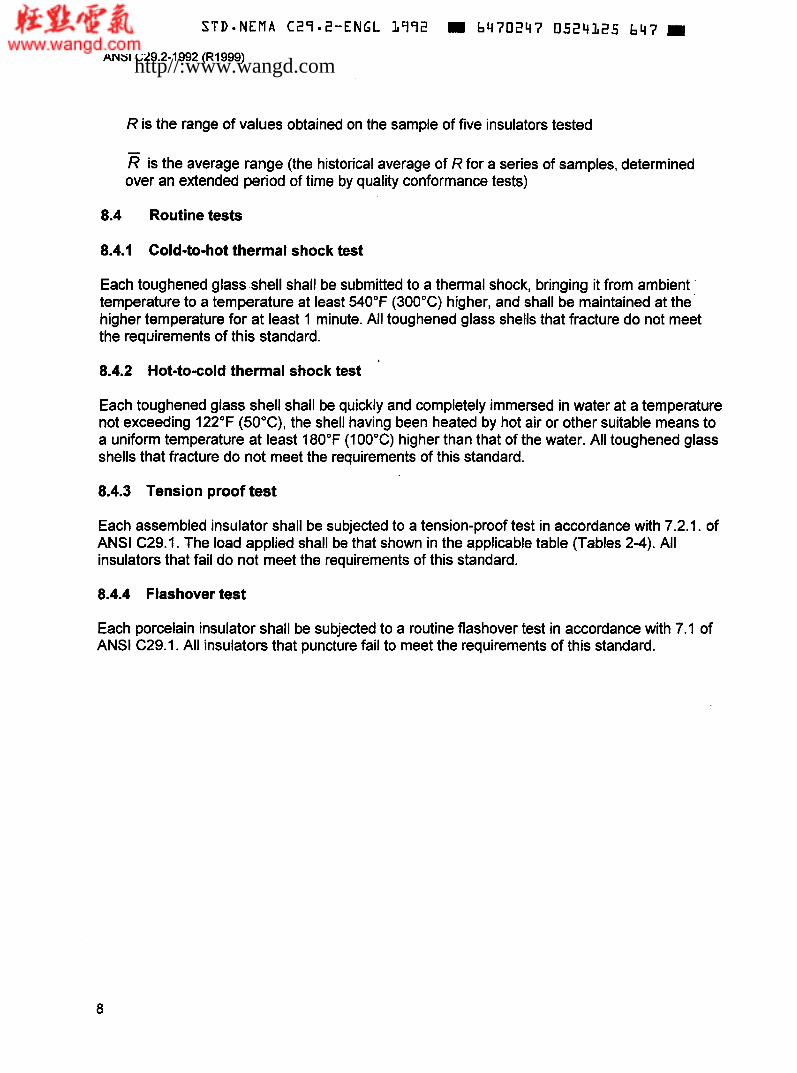
8.4 Routine tests
8.4.1 Cold-to-hot thermal shock test
Each toughened glass shell shall be submitted to a thermal shock, bringing it from ambient ' temperature to a temperature at least 540°F (300°C) higher, and shall be maintained at the higher temperature for at least 1 minute. All toughened glass shells that fracture do not meet the requirements of this standard.
8.4.2 Hot-to-cold thermal shock test
Each toughened glass shell shall be quickly and completely immersed in water at a temperature not exceeding 122°F (50°C), the shell having been heated by hot air or other suitable means to a uniform temperature at least 180°F (100°C) higher than that of the water. All toughened glass shells that fracture do not meet the requirements of this standard.
8.4.3 Tension proof test
Each assembled insulator shall be subjected to a tension-proof test in accordance with 7.2.1. of ANSI C29.1. The load applied shall be that shown in the applicable table (Tables 2-4). All insulators that fail do not meet the requirements of this standard.
8.4.4 Flashover test
Each porcelain insulator shall be subjected to a routine flashover test in accordance with 7.1 of ANSI C29.1. All insulators that puncture fail to meet the requirements of this standard.
8
http//:www.wangd.com

S TD-NEMA C29-2-ENGL 1992 W b470247 0 5 2 4 L Z b 583
ANSI C29.2-1992 (R1999)
Table 2 - Dimensions and characteristics of distribution insulators ANSI classes 52-1,52-2,52-9-A, 52-9-B)
Dimensional data See ANSI ANSI CLASS ANSI CLASS ANSI CLASS ANSI CLASS
Section (See Figure 1) (See Figure 1) (See Figure 1) (See Figure 1) C29.1-1988 52-1 52-2 52-9-A 52-9-B
Connecting hardware - Clevis Clevis Clevis Clevis coupling Leakage distance, inches (mm) Unit spacing dimension "A," inches Shell diameter dimension 'B," inches Clevis cap dimension 'C," inches Clevis cap dimension 'D," inches Clevis cap dimension "E," inches Eyebolt dimension "F," inches Eyebolt dimension "G," inches Eyebolt dimension "H," inches Cotter bolt dimension 'J," inches Mechanical Data
7( 178)
5-112
6- 1 12
11/16
11116
11/16
1 12
1 12
718
518
8-114(21 O)
5-314
8
11/16
11/16
11/16
112
17/32
11/16
518
6-314(171)
6-114
4-112
11116
11/16
11/16
1 12
1 12
718
518
6-3/4( 171)
6-114
5- 1 I4
11/16
11/16
11/16
1 12
1 12
718
518
Combined 5.2 10000 (44) 15000 (67) 10000 (44) 10000 (44) mechanical & electrical strength, pounds (kN) Mechanical impact 5.1.2.2 45 (5.0) 45 (5.0) 45 (5.0) 45 (5.0) strength, inch- pounds, (N-m) Tension proof, 7.2.1 5000 (22) 7500 (33.5) 5000 (22) 5000 (22) pounds (kN) Electrical Data
Low-frequency dry 4.2 60 65 60 60 flashover, kilovolts Low-frequency wet 4.3 30 35 30 30 ,
flashover, kilovolts Critical impulse 4.7 1 O0 115 1 O0 1 O0 flashover, positive, kilovolts Critical impulse 4.7 1 O0 115 90 90 flashover, negative, kilovolts Low-frequency 4.1 1 80 90 80 80 puncture, kilovolts Radio-Influence Voltage Data
voltage, rms to ground, kilovolts
Low-frequency test 4.7 7.5 7.5 7.5 7.5
9
http//:www.wangd.com

ANSI C29.2-1992 (R1999)
Table 3 - Dimensions and characteristics of ball-and-socket transmission insulators (ANSI classes 52-3,524,524, and 52-1 I)
Dimensional data See ANSI ANSI CLASS ANSI CLASS ANSI CLASS ANSI CLASS
Section (See Figure 2) (See Figure 2) (See Figure 2) (See Figure 2) Connecting hardware - B&STypeB B&STypeJ B&STypeK B&STypeK coupling Applicable hardware - Figures 4 & 5 Figures 5 & 6 Figures 7 & 8 Figures 7 & 8 gauges further described by: Leakage Distance, 2.5.2 11-112 (292) 11 (279) 11 (279) 15 (381) inches (mm)
dimension "A," inches
dimension "B," inches Mechanical Data
C29.1-1988 52-3 52-5 5 2 8 52-1 1
Unit spacing - 5-314 5-314 5-314 6- 1 I8
Shell diameter - 10-314 10-314 1 1-314 12-1 14
Combined 5.2 15000 (67) 25000 (1 1 1) 36000 (160) 5000 (222) mechanical & electrical strength, pounds (kN) Mechanical impact 5.1.2.2 55 (6.0) 60 (7.0) 90 (10) 90 (IO) strength, inch- pounds, (N-m) Tension proof, 7.2.1 7500 (33.5) 12500 (55.5) 18000 (80) 25000 (1 11) pounds (kN) Electrical Data
Low-frequency dry 4.2 80 80 80 80 flashover, kilovolts Low-frequency wet 4.3 50 50 50 50 flashover, kilovolts Critical impulse 4.7 125 125 125 140 flashover, positive, kilovolts Critical impulse 4.7 130 130 130 140 flashover, negative, kilovolts Low-frequency 4.1 1 110 110 110 125 puncture, kilovolts Radio-Influence Voltage Data
voltage, mis to ground, kilovolts Maximum RIV at 4.9 50 50 50 50 1 O00 kHz, microvolts
Low-frequency test 4.9 i o 10 10 10
10
http//:www.wangd.com

STDmNEMA C29-2-ENGL 1992 b470247 0524128 35b
ANSI C29.2-1992 (Rl999)
Table 4 - Dimensions and characteristics of clevis transmission insulators (ANSI classes 52-4, 52-6,52-10,52-12)
Dimensional data See ANSI ANSI CLASS ANSI CLASS ANSI CLASS ANSI CUSS C29.1-1988 524 52-6 52-1 O 52-1 2
Section (See Figure 3) (See Figure 3) (See Figure 3) (See Figure 3) Connecting hardware - Clevis Clevis Clevis Clevis coupling Leakage distance, inches (mm) Unit spacing dimension "A," inches Shell diameter dimension 'B," inches Clevis cap dimension 'C," inches Clevis cap dimension 'D," inches Clevis cap dimension 'E," inches Eyebolt dimension 'F," inches Eyebolt dimension 'G," inches Eyebolt dimension "H," inches Cotter bolt dimension "J," inches Mechanical Data
11-112 (292)
5-314
10-314
11/16
11/16
11/16
1 I2
17/32
11116
518
11 (279)
5-314
10-314
11/16
11/16
11/16
1 12
17132
11116
518
11 (279)
6- 1 12
1 1-314
11/16
718
1311 6
314
1 12
13/16
314
15 (381)
7
12-1 I4
314
1
15/16
718
911 6
1511 6
718
Combined 5.2 15000 (67) 25000 (111) 36000 (160) 50000 (222) mechanical & electrical strength, pounds (kN) Mechanical impact 5.1.2.2 55 (6.0) 60 (7.0) 90 (1 O) 90 (10) strength, inch- pounds, (N-m) Tension proof, 7.2.1 7500 (33.5) 12500 (55.5) 18000 (80) 25000 (1 11) pounds (kN) Electrical Data
Low-frequency dry 4.2 80 80 80 80 flashover, kilovolts Low-frequency wet 4.3 50 50 50 50 flashover, kilovolts Critical impulse 4.7 125 125 125 140 flashover, positive, kilovolts Critical impulse 4.7 130 130 130 140 flashover, negative, kilovolts Low-frequency 4.1 1 110 110 110 125 puncture, kilovolts Radio-lnfluence Voltage Data
voltage, rms to ground, kilovolts
Low-frequency test 4.7 10 10 10 10
11
http//:www.wangd.com
~~ ~- ~~ ~~ ~
S T D - N E M A C29-2-ENGL 1992 = 6470247 0524329 292
ANSI C29.2-1992 (RI999)
IN
r,
cuss %?-@-A
(Nol0 11
CUSS 52-1. s2-2
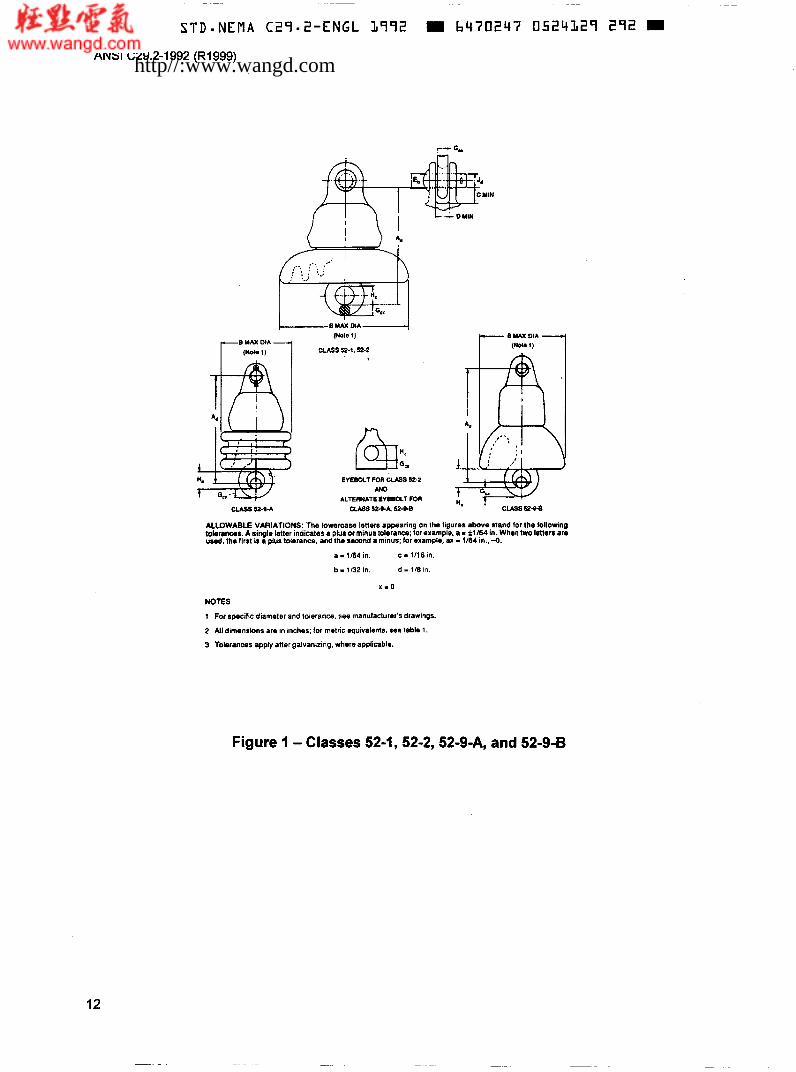
ALLOWABLE VARIATIONS: The lowercase letter8 appearing on the ligures a b w e stand for lhe following tobruiaa. A tingle lener indicates a plu$ or minus tolerance; lor example, a - i l164 in. When h o leiler8 are u d . th. lirat ia a plus tolerance, and the remnd a minus: for exampie, ax - 1/64 in.. -0.
a - 1/64 in.
b - tß2 in . d - l a i n .
c 1116 in.
X.0
NOTES
1 For specific diameter and tolerance. see manufacturer's drawings.
2 All dimensions are in inches: tor mmtric equivalents. sea table 1.
3 Tolerancas apply after galvanizing. where applimble.
Figure 1 - Classes 52-1,52-2,52-9-A, and 52-9-B
12
http//:www.wangd.com

STD*NEMA C29-2-ENGL L992 6470247 0524130 T O 4 W
ANSI C29.2-1992 (R1999)
A
I
I B MAX DIA -1 (Noie 1)
NOTES
1 For spodfic diameirr and tolerance, roe monufacturer'sdrawingr.
2 Tho cannrt3ing irngih of a string of 8ix insulaion roloclod at random shall k equal to six limas the nomi- nil apwing ai t h . insulators *3/4 in ( f i 9.1 mm). 3 Dimentiona and toirrances shall be determined. after galvanizing (where applicablo). by the ball and d o l gaugrr in?@onr 4.5.6.7. and 8.
4 Connoding hardware p u t s ara designated by Type according to applicable gauger as follom:
Type B defined by gauges in ligures 4 and 5.
Type J delinod by gauges in figurir 5 and 6.
Type K difiMd by gauges in figures 7 and 8.
Figure 2 - Ball-and-socket suspension insulator classes 52-3, 52-5,52-8, and 52-1 1
13
http//:www.wangd.com

STD-NEMA C29.2-ENGL L99S = b470247 05Z4L3L 940 W
ANSI C29.2-1992 (RI999)
(Note 1)
ALLOWABLE VARIATIONS: The lowercase letiers appearing on the figuro above stand for the folkwing erantxa. A single letter indicates a plus or minus tolerance; for example, a - f1164 in. When two letters u d . the fira is a plus tolerance. and the second a minus; for examph, ax - 1184 in., -0.
a I 1/64 in.
b = 1132 in.
c - 1/16 in.
d - 116 in.
t0l- aro
x - o NOTES
1 Fot specific diameter and tolerance. see manufacturer's drawings.
2 All dimenrions are in inches; lor metric equivalents, see table 1.
3 The connecting length oí a string of six insulators solectod at random rhail be q u a l lo six times the nomi- nal spacing dl the insulators f3/4 in (i19.1 mm).
4 Tolerances apply sRer galvanizing, whoro applicable.
Figure 3 - Clevis suspension insulator classes 524, 52-6,52-IO, and 52-1 2
14
http//:www.wangd.com

ANSI C29.2-1992 (R1999)
boG:o_I METMOD OF GAGING
SECTION &-A
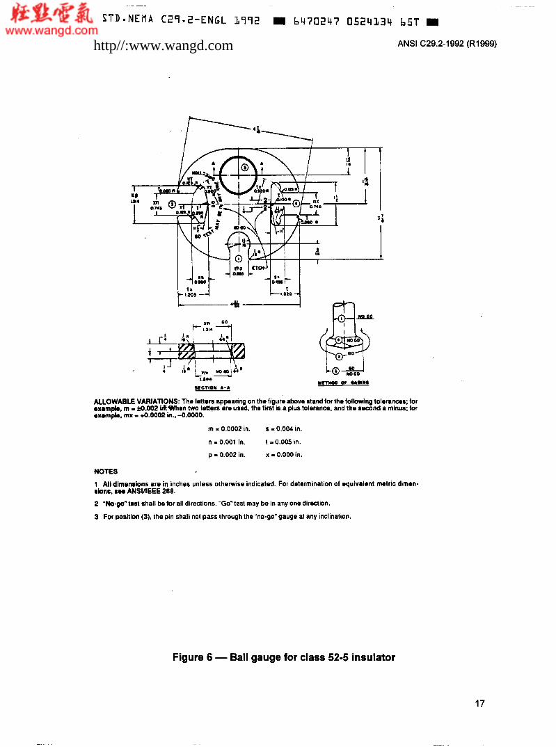
ALLOWASLE VARIATIONS: The htten appearing on tho figure above stand for the iollowiw tolorams; lor exunplo. m - Io.002 in. When two letters are usod. the firrt b a phis toleran-, and lhe s m n d a minus; lor oxampb. mx - *0.0002 in., 6.0000.
m = 0.0002 in.
n I 0.CtOl in.
p = 0.002 in.
s = O . O U in.
t - 0.005 in.
x - 0.000 in.
NOTES
1 All dimensions are in inches unless otherwise indicated. For determination of equivalent metric dimen- sions. 888 ANSUIEEE 268.
2 'Nogo' test shall be for all diraclions 'Go'test may bo in any one direction.
3 For position (3, the pin shall not pass through the "no-go" gauge at any inclination.
Figure 4 - Bali gauge for class 52-3 insulator
15
http//:www.wangd.com

ANSI C29.2-1992 (R1999)
ALLOWABLE VARIAWNS: The letters appearing on the figure above stand for the following tolerances; for example, m = fo.002 in..When two letters are used, the first k a plus tolerance. and the second a minus; loi exampb. mx =+0.0002 in.. -û.OOOO.
m = 0.0002 in.
n = 0.001 in.
p = 0.002 in.
s - O.OC4 in.
t I 0.005 in.
x - 0.000 in.
* NOTES
1 All dimensions are in inches unless otherwise indicated. For determination of equivalent metric dimsn- dons. see ANSIAEEE 268.
2 Check for'no-go" dimensions along axis A-A and B-B.
Figure 5 - Socket gauge for class 52-3 and 52-5 insulator
16
http//:www.wangd.com
~ ~~
S T D * N E M A C29.2-ENGL 1992 6470243 0524334 657' W
ANSI C29.2-1992 (R1999)
ALLOWABLE VARIAflONS: Tho lotten appearing on the figure a t w e stand for lha folbwing tolerinces; tor eumpb, m I fo.002 ¡!kWhm Wo lO(torS aro used. the first is a plus tolerance, and tho second a minus; lor .urnpi., mx - 4.0002 in.. -0.ooOO.
m - 0.0002 in.
n I 0.001 in.
p - 0.002 in.
s - 0.004 in.
1 I 0.005 in.
x - 0.000 in.
NOES
1 All dlmsntbnr are in inches unless otherwise indicated. For determination of equivalent metric dimen- rbnr. BOO ANSUIEEE 268.
2 "o-go' test shall be for all directions. "Go" test may be in any ono direction.
3 For wsltlon (3). the pin shall no1 pass through the ho-go'gauge at any inclination.
Figure 6 - Ball gauge for class 52-5 insulator
17
http//:www.wangd.com

S T D - N E M A C27*2-ENGL 1772 H 6470247 0524135 576 H
ANSI C29.2-1992 (RI999)
KLOWABLE VAdIATIONS: The letters appearing on the tigure above stand toi the lollowing lolerances; for example. m - t0.002 in. When two letters are used, the first is a plus tolerance, and lhe SocDnd a minus; for oxampio. mx - +0.0002 in., 4.0000.
m = 0.0002 in.
n I 0 . W in.
p = 0.002 in.
s = 0.004 in.
t - 0.005 in.
x = 0.000 in.
NOTES
1 All dimonrion8 are in inches unless otherwise indicated. For determination of equivalent metric dimen- sions. see ANSHEEE 268.
2 "o-go' lest shall be lor all directions. 'Go'tost may be In any one direction.
3 For position (3). lhe pin shall not pass through the 'no-go'gauge at any inclination.
Figure 7 - Ball gauge for class 52-8 and 52-1 1 insulators
18
http//:www.wangd.com
~~
S T D * N E M A C27-2-ENGL 1992 = 6470247 052413b 422 M
ANSI C29.2-1992 (Rl999)
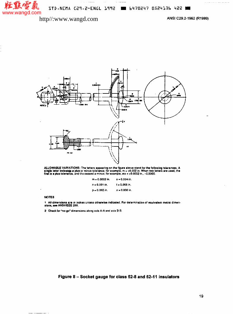
ALLOWABLE VARIATIONS: The letters appearing on the figure above stand foi tho following tolerances. A iingk kttrr indicatg a plus or minus tolerance; for example, m I iO.002 in. When two letters are Y&, the fii8l is ipks tdrrancs. and the second a minus: lor example. mx - +0.0002 in.. 4.0000.
m I 0.0002 in.
n I 0.001 in.
p - 0.002 in.
s = 0.004 in.
t I 0.005 in
x .I 0.OW in.
NOTES
1 All dimrnrions are in inches unless olherwise indicated. For determination of equivaleni metric dimen- sions, roo ANSUIEEE 268.
2 Chock for 'nopo' dimensions along axis A-A and axis E-8
Figure 8 - Socket gauge for class 52-8 and 52-1 1 insulators
19
http//:www.wangd.com

STD.NEMA C27.2-ENGL 1972 m b470247 0524137 367
ANSI C29.2-1992 (R1999)
Combined mechanical and I electrical strength rating taken as equal to 100% ioo--------------------------------------*
Figure 9 - Schematic representation of thermal-mechanical performance test
20
http//:www.wangd.com

~ ~ ~~
~~ ~~~
S TD-NEMA C29.2-ENGL LqVZ b470247 0524338 2 T C
ANSI C29.2-1992 (R1999)
Figure 10 - Impact testing machine
21
http//:www.wangd.com

STDmNEMA C29-2-ENGL 1972 6470247 0524137 131 ANSI C29.2-1992 (R1999)
DETAILS OF 808
Figure I O (concluded)
NOTES
Correct positioning of insulator for test: When the pendulum is hanging free, the point of contact between the soft capper nose and insulator shall fall on the centerline passing through the nose of the bob.
Mounting the insulator: The eye bolt A is adjusted by nuts 1 and 2 to bring the lower edge of the rim of the unit to be tested to within approximately 1/16 inch of the freely hanging pendulum nose. Nuts 1 and 2 are also adjusted to place cap B approximately 114 inch away from the side of frame C. The insulator is then inserted and tightened with nut D so that cap B is drawn firmly against frame C. The insulator is then under a load of 2000 pounds and is in the proper position, and the effect of the spring is eliminated. The pendulum and scale are moved up or down to obtain the correct position.
Determining effective weight of pendulum: Raise the pendulum until the indicator is opposite the 90-inch-pound mark. With the pendulum in this position, place the copper nose of the bob on scales and add lead until the scale reads 2.57 pounds.
Impact testing: For impact testing of class 52-9 insulators, invert the steel bob from the position shown in figure and shorten the steel tube to maintain the 35inch pendulum length.
Spring specification: The spring is made of 1R-inch-diameter steel wire, so treated and constructed that a force of 2000 pounds will compress the spring 0.25 inch in overall length.
All dimensions are in inches unless otherwise indicated. For determination of equivalent metric dimensions, see ANSIAEEE 268.
Tube to be welded at axle and pinned at bob.
3/8-inch bolts unless noted.
Ail members made of steel, painted unless otherwise noted.
22
http//:www.wangd.com

ANSI C29.2-1992 (R1999)
Annex A (informative)
Packaging
Packaging of insulators should be such as to afford reasonable and proper protection to the insulators in shipping and handling.
Each box or container should be marked with the number of insulators contained therein, the catalog number, class number, or a description of the contents; and the manufacturer's name.
http//:www.wangd.com

~ ~ ~
S T D * N E M A C29-2-ENGl- 1992 = 6470247 0524343 89T
ANSI C29.2-1992 (Rl999)
Annex B (informative) Bibliography
ASTM Manual of Presentation of Data and Control Chart Analysis, 6th edition 1990 (ASTM Manual Series; MNL7)
25
Previous page is blank.
http//:www.wangd.com