Embed Size (px)
Citation preview
Document No.: M-W3099AE-8.0
ANRITSU CORPORATION
MX269011A W-CDMA/HSPA Downlink Measurement Software
Operation Manual Remote Control
Eighth Edition
• For safety and warning information, please read this manual before attempting to use the equipment.
• Additional safety and warning information is provided within the MS2690A/MS2691A/MS2692A Signal Analyzer Operation Manual (Mainframe operation), MS2830A Signal Analyzer Operation Manual (Mainframe operation), or MS2850A Signal Analyzer Operation Manual (Mainframe operation) and MX269011A W-CDMA/HSPA Downlink Measurement Software Operation Manual (Operation). Please also refer to these documents before using the equipment.
• Keep this manual with the equipment.
ii
Safety Symbols To prevent the risk of personal injury or loss related to equipment malfunction, Anritsu Corporation uses the following safety symbols to indicate safety-related information. Ensure that you clearly understand the meanings of the symbols BEFORE using the equipment. Some or all of the following symbols may be used on all Anritsu equipment. In addition, there may be other labels attached to products that are not shown in the diagrams in this manual.
Symbols used in manual This indicates a very dangerous procedure that could result in serious injury or death if not performed properly.
This indicates a hazardous procedure that could result in serious injury or death if not performed properly. This indicates a hazardous procedure or danger that could result in light-to-severe injury, or loss related to equipment malfunction, if proper precautions are not taken.
Safety Symbols Used on Equipment and in Manual The following safety symbols are used inside or on the equipment near operation locations to provide information about safety items and operation precautions. Ensure that you clearly understand the meanings of the symbols and take the necessary precautions BEFORE using the equipment.
This indicates a prohibited operation. The prohibited operation is indicated symbolically in or near the barred circle.
This indicates an obligatory safety precaution. The obligatory operation is
indicated symbolically in or near the circle. This indicates a warning or caution. The contents are indicated symbolically in or
near the triangle. This indicates a note. The contents are described in the box. These indicate that the marked part should be recycled.
MX269011A W-CDMA/HSPA Downlink Measurement Software Operation Manual Remote Control 15 August 2008 (First Edition) 28 April 2017 (Eighth Edition) Copyright © 2008-2017, ANRITSU CORPORATION. All rights reserved. No part of this manual may be reproduced without the prior written permission of the publisher. The contents of this manual may be changed without prior notice. Printed in Japan
DANGER
WARNING
CAUTION

iii
Notes On Export Management This product and its manuals may require an Export License/Approval by the Government of the product's country of origin for re-export from your country. Before re-exporting the product or manuals, please contact us to confirm whether they are export-controlled items or not. When you dispose of export-controlled items, the products/manuals need to be broken/shredded so as not to be unlawfully used for military purpose.
Cautions against computer virus infection • Copying files and data Only files that have been provided directly from Anritsu or generated
using Anritsu equipment should be copied to the instrument. All other required files should be transferred by means of USB or
CompactFlash media after undergoing a thorough virus check. • Adding software Do not download or install software that has not been specifically
recommended or licensed by Anritsu. • Network connections Ensure that the network has sufficient anti-virus security protection in
place.

iv
I
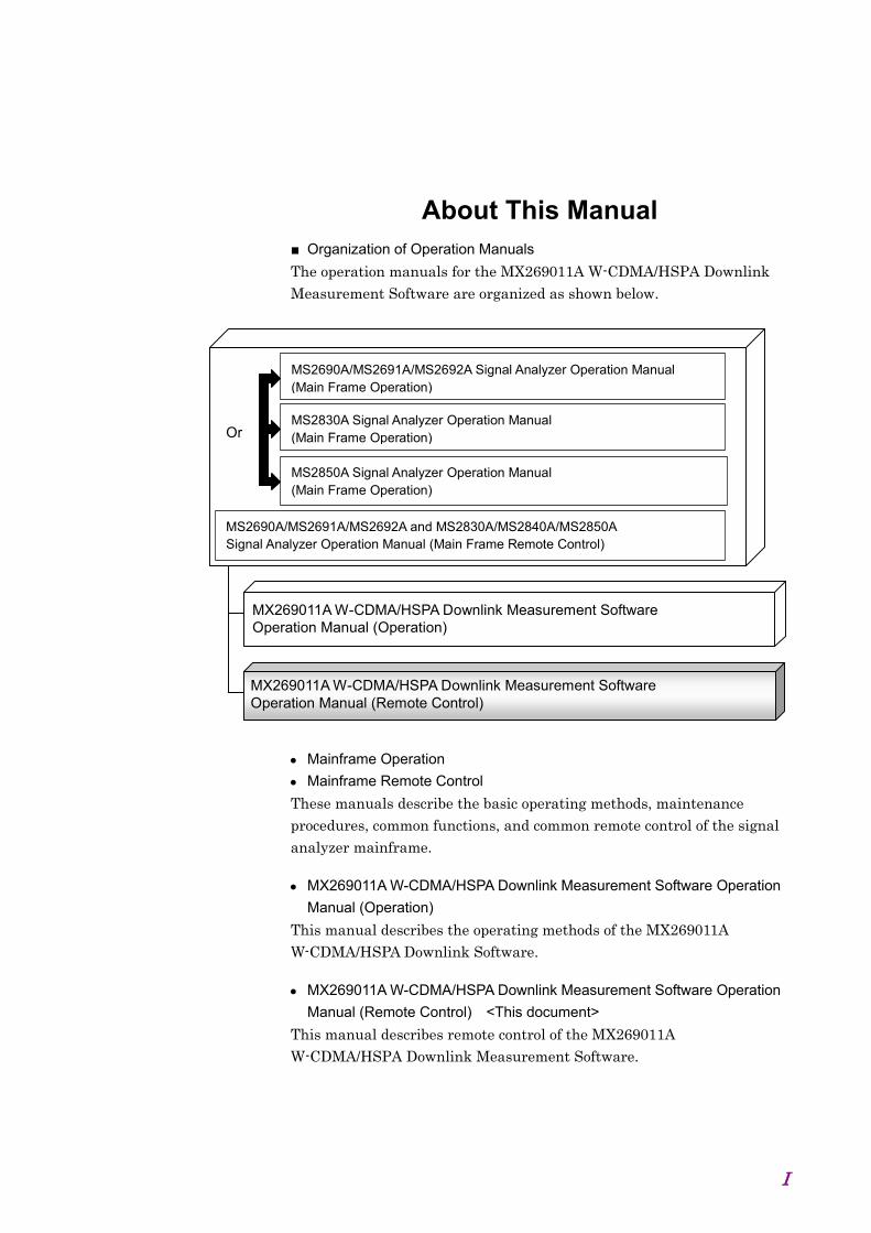
About This Manual ■ Organization of Operation Manuals
The operation manuals for the MX269011A W-CDMA/HSPA Downlink Measurement Software are organized as shown below.
MX269011A W-CDMA/HSPA Downlink Measurement Software Operation Manual (Operation)
MX269011A W-CDMA/HSPA Downlink Measurement Software Operation Manual (Remote Control)
MS2690A/MS2691A/MS2692A Signal Analyzer Operation Manual (Main Frame Operation)
MS2690A/MS2691A/MS2692A and MS2830A/MS2840A/MS2850A Signal Analyzer Operation Manual (Main Frame Remote Control)
MS2850A Signal Analyzer Operation Manual (Main Frame Operation)
Or MS2830A Signal Analyzer Operation Manual (Main Frame Operation)
Mainframe Operation
Mainframe Remote Control
These manuals describe the basic operating methods, maintenance procedures, common functions, and common remote control of the signal analyzer mainframe.
MX269011A W-CDMA/HSPA Downlink Measurement Software Operation
Manual (Operation)
This manual describes the operating methods of the MX269011A W-CDMA/HSPA Downlink Software.
MX269011A W-CDMA/HSPA Downlink Measurement Software Operation
Manual (Remote Control) <This document>
This manual describes remote control of the MX269011A W-CDMA/HSPA Downlink Measurement Software.
II
Table of Contents
About This Manual........................................ I
Chapter 1 Overview .................................... 1-1 1.1 Outline ........................................................................... 1-2
1.2 Basic Flow of Control .................................................... 1-3
1.3 How to use the Native Mode ......................................... 1-24
1.4 Character Programs Available for Setting
Numeric Program Data ................................................. 1-29
Chapter 2 SCPI Device Message Details .. 2-1 2.1 Selecting applications ................................................... 2-8
2.2 Settings parameters ...................................................... 2-15
2.3 Setting of System Parameters ...................................... 2-27
2.4 Utility Functions ............................................................. 2-63
2.5 Common Measurement Function ................................. 2-67
2.6 ACP/Channel Power/OBW/SEM measurement function 2-82
2.7 Modulation Measurement Function .............................. 2-94
2.8 Code Domain measurement function ........................... 2-138
2.9 Code vs Time measurement function ........................... 2-174
Chapter 3 SCPI Status Register ................ 3-1 3.1 Querying Measurement Status ..................................... 3-2
3.2 STATus:QUEStionable Register ................................... 3-3
3.3 STATus:OPERation Register ....................................... 3-15

III
1
2
3

IV.

Chapter 1 Overview
1-1
1
Overview
This chapter provides an overview of the remote control of the MX269011A W-CDMA/HSPA Downlink Measurement Software (hereinafter, referred to as “this application”).
1.1 Outline ........................................................................... 1-2
1.1.1 Interface ............................................................ 1-2 1.1.2 Controlled Application....................................... 1-2
1.2 Basic Flow of Control .................................................... 1-3 1.2.1 Initialization ....................................................... 1-5 1.2.2 Basic Parameter Settings ................................. 1-7 1.2.3 Modulation/Code Domain/Code vs Time
Common Settings ............................................. 1-8 1.2.4 Modulation Measurement ............................... 1-10 1.2.5 Code Domain Measurement .......................... 1-12 1.2.6 Code vs Time Measurement .......................... 1-14 1.2.7 ACP (Adjacent Channel Power)
Measurement .................................................. 1-16 1.2.8 Channel Power Measurement ........................ 1-18 1.2.9 OBW (Occupied Bandwidth) Measurement ... 1-20 1.2.10 SEM (Spectrum Emission Mask)
Measurement .................................................. 1-21 1.2.11 Signal Analyzer/Spectrum Analyzer
Switching ........................................................ 1-22 1.3 How to use the Native Mode ....................................... 1-24 1.4 Character Programs Available for Setting Numeric
Program Data.............................................................. 1-29
Chapter 1 Overview
1-2
1.1 Outline This application can be controlled from an external controller (PC) by remote control commands using the MS2690/MS2691/MS2692A, MS2830A, or MS2850A Signal Analyzer (hereafter referred to as “this instrument”). Remote control commands for this application are in the SCPI format defined by the SCPI Consortium.
1.1.1 Interface This instrument has GPIB, Ethernet, and USB interfaces for remote control. Only one interface can be used at a time.
The interface is determined automatically when a command is received at the start of communication. The interface enters the remote state when a remote command is detected from the external controller (PC). At remote-interface operation, the front panel lamp lights; the lamp is off at local-interface operation.
Refer to the “MS2690A/MS2691A/MS2692A and MS2830A/MS2840A/MS2850A Signal Analyzer manual (Mainframe Remote Control)” for more details about remote control and interface setting.
1.1.2 Controlled Application Two kinds of remote control commands can be used with this instrument: commands that are common to all applications (hereafter common commands), and other commands unique to a specific application. Common commands can be executed at any time and do not depend on the currently controlled application. However, when a command unique to a specific application is executed at another application, the command is not executed and an error occurs.
In this instrument, multiple applications can be activated at the same time. Only one application resource can be executed per piece of hardware at one time. This application performs a measurement for an input signal by using the resource of RF input. Thus, this application cannot be executed at the same time with another application using the same resource. In order to execute a function unique to the application by using remote control, you need to select this application while it has been loaded. Furthermore, this application can be executed at the same time as another application that uses by itself a resource not used by this application, such as the Vector Signal Generator Option.

1.2 Basic Flow of Control
1-3
1
Overview
1.2 Basic Flow of Control This section explains the basic remote control command programming for measuring a W-CDMA Downlink signal.
Figure 1.2-1 shows the control flow for a basic test. Note the parameter settings for the measurement, type of measurement function, and measurement execution order (although the measurement order can change).
Modulation Measurement
ACP Measurement
Channel Power Measurement
OBW Measurement
End
Basic Parameter Settings
Initialization Alteration of
conditions
Modulation/Code Domain /Code vs Time
Common Settings
Start
SEM Measurement
Figure 1.2-1 Basic Test Flow
Chapter 1 Overview
1-4
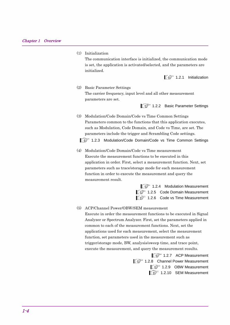
(1) Initialization The communication interface is initialized, the communication mode is set, the application is activated/selected, and the parameters are initialized.
1.2.1 Initialization
(2) Basic Parameter Settings The carrier frequency, input level and all other measurement parameters are set.
1.2.2 Basic Parameter Settings
(3) Modulation/Code Domain/Code vs Time Common Settings Parameters common to the functions that this application executes, such as Modulation, Code Domain, and Code vs Time, are set. The parameters include the trigger and Scrambling Code settings.
1.2.3 Modulation/Code Domain/Code vs Time Common Settings
(4) Modulation/Code Domain/Code vs Time measurement Execute the measurement functions to be executed in this application in order. First, select a measurement function. Next, set parameters such as trace/storage mode for each measurement function in order to execute the measurement and query the measurement result.
1.2.4 Modulation Measurement 1.2.5 Code Domain Measurement 1.2.6 Code vs Time Measurement
(5) ACP/Channel Power/OBW/SEM measurement Execute in order the measurement functions to be executed in Signal Analyzer or Spectrum Analyzer. First, set the parameters applied in common to each of the measurement functions. Next, set the applications used for each measurement, select the measurement function, set parameters used in the measurement such as trigger/storage mode, BW, analysis/sweep time, and trace point, execute the measurement, and query the measurement results.
1.2.7 ACP Measurement 1.2.8 Channel Power Measurement
1.2.9 OBW Measurement 1.2.10 SEM Measurement

1.2 Basic Flow of Control
1-5
1
Overview
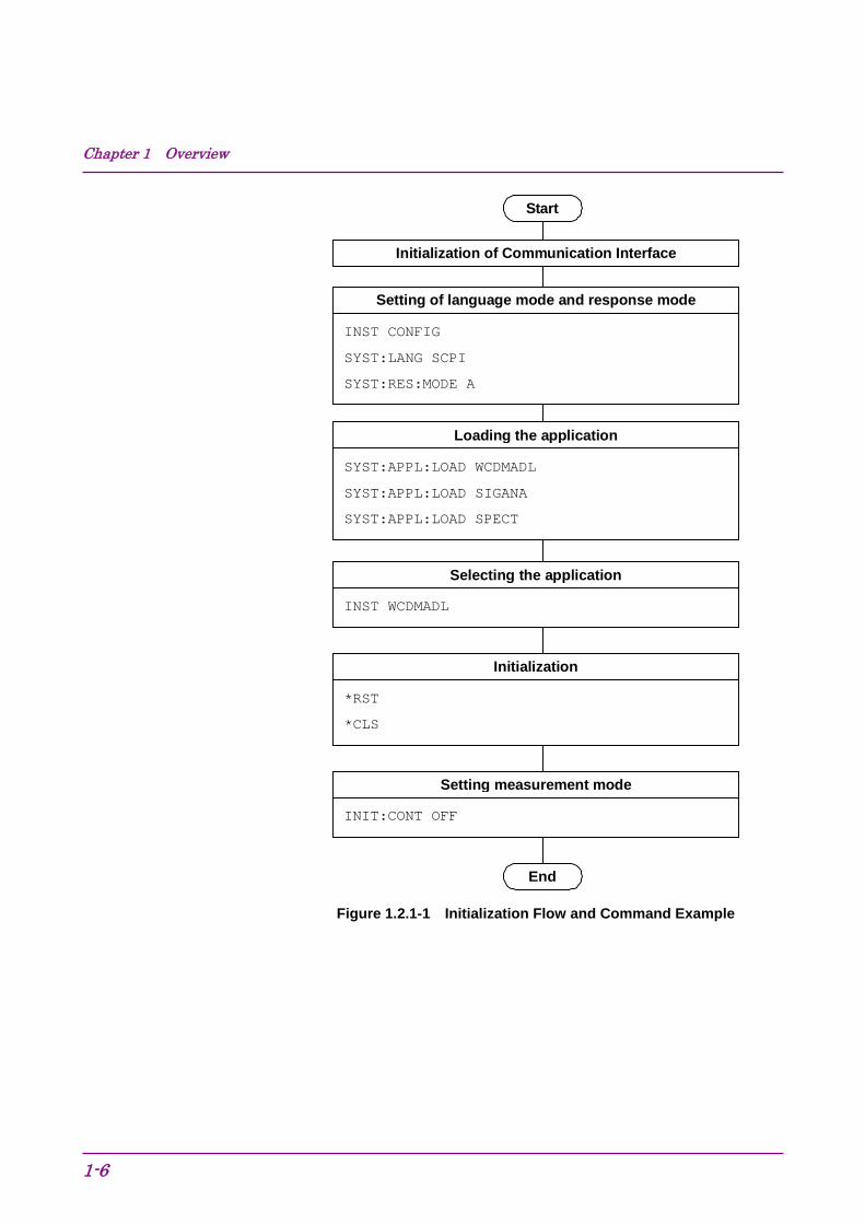
1.2.1 Initialization As part of the initial settings, perform the preparations for using the measuring instrument and the application. The following actions are included in the initial settings.
(1) Initialization of Communication Interface The remote control interface to be used is initialized so sending and receiving of commands can start. Refer to the “MS2690A/MS2691A/MS2692A and MS2830A/MS2840A/MS2850A Signal Analyzer manual (Mainframe Remote Control)” for details about the remote control interface.
(2) Setting Language Mode and Response Format The language mode and the response format used to communicate are set. Refer to the “MS2690/MS2691/MS2692A and MS2830A/MS2840A/MS2850A Signal Analyzer manual (Mainframe Remote Control)” for details about the language mode and response format.
(3) Loading Application The application is loaded. The signal analyzer and spectrum analyzer applications should be loaded too.
(4) Selecting Application The target application is selected.
(5) Initialization All parameters and states are reset at initialization.
(6) Setting Measurement Mode. After initialization, the measurement mode is at continuous measurement mode. To select single measurement mode, switch to the single measurement mode.
Chapter 1 Overview
1-6
Start
Loading the application
End
Setting of language mode and response mode
Initialization of Communication Interface
INST CONFIG
SYST:LANG SCPI
SYST:RES:MODE A
SYST:APPL:LOAD WCDMADL
SYST:APPL:LOAD SIGANA
SYST:APPL:LOAD SPECT
Selecting the application
INST WCDMADL
Initialization
*RST
*CLS
Setting measurement mode
INIT:CONT OFF
Figure 1.2.1-1 Initialization Flow and Command Example
1.2 Basic Flow of Control
1-7
1
Overview
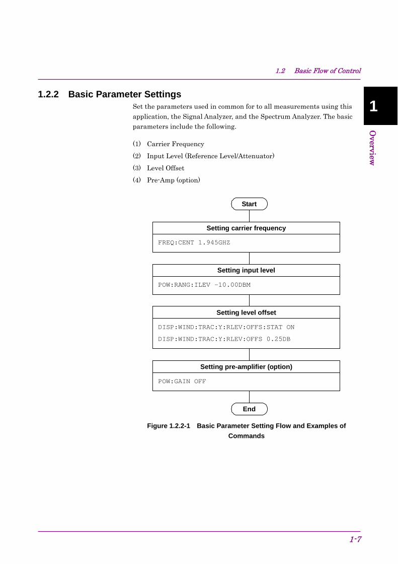
1.2.2 Basic Parameter Settings Set the parameters used in common for to all measurements using this application, the Signal Analyzer, and the Spectrum Analyzer. The basic parameters include the following.
(1) Carrier Frequency
(2) Input Level (Reference Level/Attenuator)
(3) Level Offset
(4) Pre-Amp (option)
Start
End
Setting carrier frequency
FREQ:CENT 1.945GHZ
POW:RANG:ILEV -10.00DBM
Setting level offset
DISP:WIND:TRAC:Y:RLEV:OFFS:STAT ON
DISP:WIND:TRAC:Y:RLEV:OFFS 0.25DB
Setting pre-amplifier (option)
POW:GAIN OFF
Setting input level
Figure 1.2.2-1 Basic Parameter Setting Flow and Examples of Commands
Chapter 1 Overview
1-8
1.2.3 Modulation/Code Domain/Code vs Time Common Settings Set the parameters used in common for the Modulation/Code Domain /Code vs Time measurement functions executed in this application. Unless specified, there is no specific parameter setting order.
(1) Trigger
(a) Trigger Switch
(b) Trigger Source
(c) Trigger Slope
(d) Trigger Delay
(2) Scrambling Code Synchronization
(3) Scrambling Code (when Scrambling Code Synchronization is set to User Defined)
(4) Frame Sync Code Type
(5) Frame Sync Spreading Factor (when Frame Sync Code Type is set to User Defined)
(6) Frame Sync Code Number (when Frame Sync Code Type is set to User Defined)
(7) Channel Detection
(8) Origin Offset
(9) Active Code Threshold
(10) PICH CH Number

1.2 Basic Flow of Control
1-9
1
Overview
Setting of PICH CH Number
EVM:PICH:CCOD 0
End
Setting of Trigger
TRIG ON
TRIG:SOUR EXT
TRIG:SLOP POS
TRIG:DEL 0
EVM:SYNC:SCSY SCH
Setting of Frame Sync Code Type
EVM:SYNC:FSCT CPIC
Setting of Channel Detection
EVM:CDET AUTO
Setting of Scrambling Code Synchronization
Setting of Active Code Threashold
CALC:EVM:ASET:THR -30DB
Start
Setting of Origin Offset
EVM:ORIG INCL
Figure 1.2.3-1 Flow of Common Settings for Modulation/Code Domain and Examples of Commands

Chapter 1 Overview
1-10
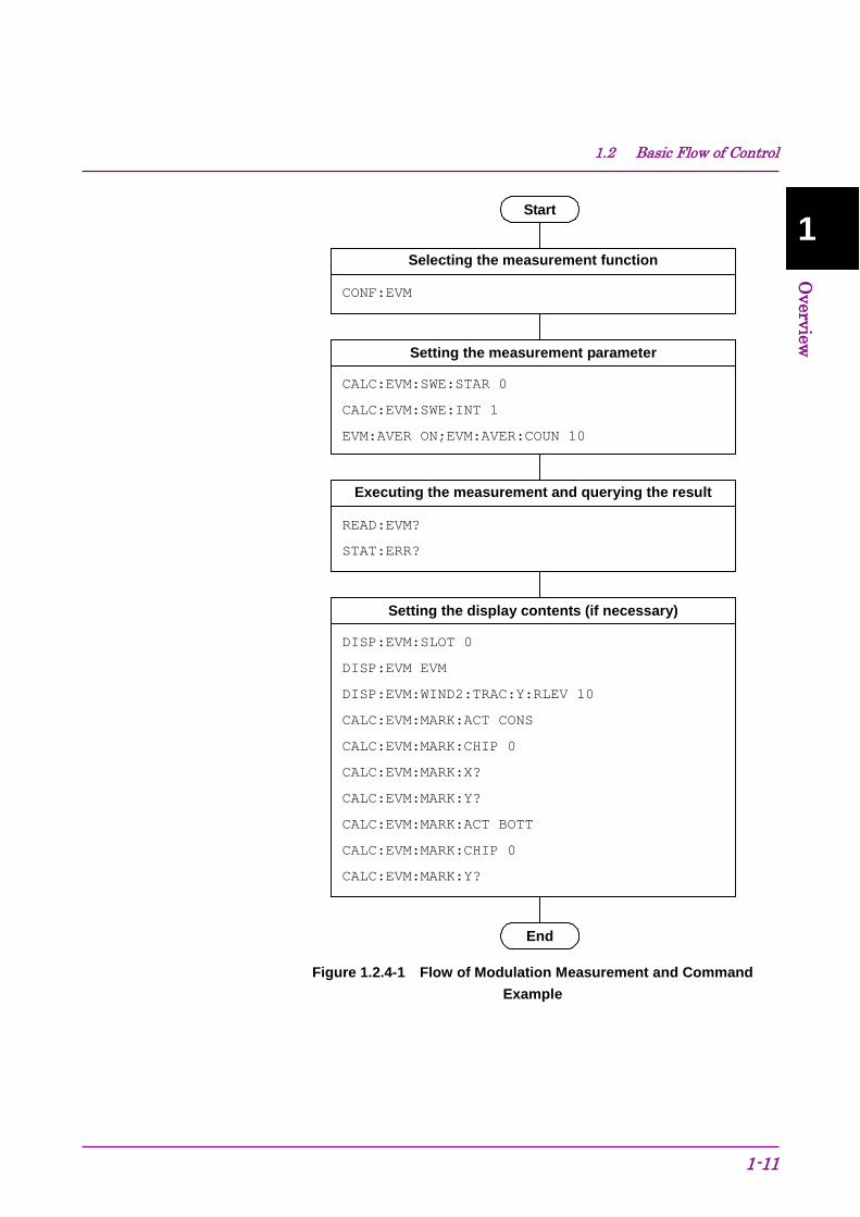
1.2.4 Modulation Measurement This executes the Modulation analysis function as follows:
(1) Select the measurement function.
(2) Set the measurement parameters. The following parameters are only applied to Modulation measurement:
(a) Starting Slot Number
(b) Measurement Interval
(c) Storage
(3) Execute measurement and query the result.
(4) Setting the display contents This setting is required when displaying measured results on the screen or when querying specific data.
(a) Trace Mode
(b) Scale
(c) Marker
(d) Target Slot Number
1.2 Basic Flow of Control
1-11
1
Overview
Start
End
Selecting the measurement function
CONF:EVM
CALC:EVM:SWE:STAR 0
CALC:EVM:SWE:INT 1
EVM:AVER ON;EVM:AVER:COUN 10
Executing the measurement and querying the result
READ:EVM?
STAT:ERR?
Setting the display contents (if necessary)
DISP:EVM:SLOT 0
DISP:EVM EVM
DISP:EVM:WIND2:TRAC:Y:RLEV 10
CALC:EVM:MARK:ACT CONS
CALC:EVM:MARK:CHIP 0
CALC:EVM:MARK:X?
CALC:EVM:MARK:Y?
CALC:EVM:MARK:ACT BOTT
CALC:EVM:MARK:CHIP 0
CALC:EVM:MARK:Y?
Setting the measurement parameter
Figure 1.2.4-1 Flow of Modulation Measurement and Command Example

Chapter 1 Overview
1-12
1.2.5 Code Domain Measurement This executes the Code Domain measurement as follows:
(1) Select the measurement function.
(2) Set the measurement parameter. The following parameters are only applied to Code Domain measurement:
(a) Starting Slot Number
(b) Measurement Interval
(3) Execute the measurement and query the result.
(4) Setting the display contents (Required when displaying measured results on the screen or when querying specific data.)
(a) Code Number
(b) Target Slot Number
(c) Trace Mode
(d) Scale
(e) Marker

1.2 Basic Flow of Control
1-13
1
Overview
Start
End
Selecting the measurement function
CONF:CDP
CALC:CDP:SWE:STAR 0
CALC:CDP:SWE:INT 1
Executing the measurement and querying the result
READ:CDP?
STAT:ERR?
Setting the display contents (if necessary)
CALC:CDP:CODE 0
DISP:CDP:SLOT 0
DISP:CDP CPOW
DISP:CDP:WIND7:TRAC:Y:RLEV 40
CALC:CDP:MARK:SYMB 0
CALC:CDP:MARK:Y?
DISP:CDP:CDOM POW
CALC:CDP:MARK:Y:CDOM:CPOW?
CALC:CDP:MARK:Y:CDOM:CERR?
Setting the measurement parameter
Figure 1.2.5-1 Flow of Code Domain Measurement and Command Example

Chapter 1 Overview
1-14
1.2.6 Code vs Time Measurement This executes the Code vs Time measurement as follows:
(1) Select the measurement function.
(2) Set the measurement parameter. The following parameters are only applied to Code vs Time measurement:
(a) Measurement Interval
(3) Execute the measurement and query the result.
(4) Setting the display contents This setting is required when displaying measured results on the screen or when querying specific data.
(a) Trace Mode
(b) Scale
(c) Marker
(d) Code vs Time Target Code
(e) Code vs Time Slot Number

1.2 Basic Flow of Control
1-15
1
Overview
Start
End
Selecting the measurement function
CONF:CVT
CALC:CVT:SWE:INT 20
Executing the measurement and querying the result
READ:CVT?
STAT:ERR?
Setting the display contents (if necessary)
DISP:CVT POW
DISP:CVT:WIND8:TRAC:Y:RLEV 60
CALC:CVT:SLOT 0
CALC:CVT:MARK:Y:CVT:MPOW?
CALC:CVT:MARK:MNUM 0
CALC:CVT:MARK:Y:CDOM:CPOW?
Setting the measurement parameter
Figure 1.2.6-1 Flow of Code vs Time Measurement and Command Example

Chapter 1 Overview
1-16
1.2.7 ACP (Adjacent Channel Power) Measurement ACP measurement is basically executed in the following order:
(1) Selecting application and the measurement function Select either Signal Analyzer or Spectrum Analyzer as the application to execute the ACP measurement function. The application is switched to the selected one if the ACP measurement function is selected. The basic parameter values are applied to the selected application. Subsequently, only the command/query available in the selected application can be used.
(2) Setting measurement parameters The following parameters apply only to the specific application selected.
(a) Trigger
(b) Time Length/Filter Type/Storage, etc. (in Signal Analyzer)
(c) Sweep Time/Filter Type/Storage, etc. (in Spectrum Analyzer)
(3) Executing the measurement and querying the result
(4) Setting the display contents This setting is for displaying the result on the screen. However, you do not need to perform the setting if you only query the result through remote control.

1.2 Basic Flow of Control
1-17
1
Overview
Start
End
Selecting the application to be used and the measurement function
CONF:SWEP:ACP
TRIG OFF
Executing the measurement and querying the result READ:ACP? STAT:ERR?
Setting the measurement parameters
Figure 1.2.7-1 Flow of ACP Measurement using Spectrum Analyzer and Command Example

Chapter 1 Overview
1-18
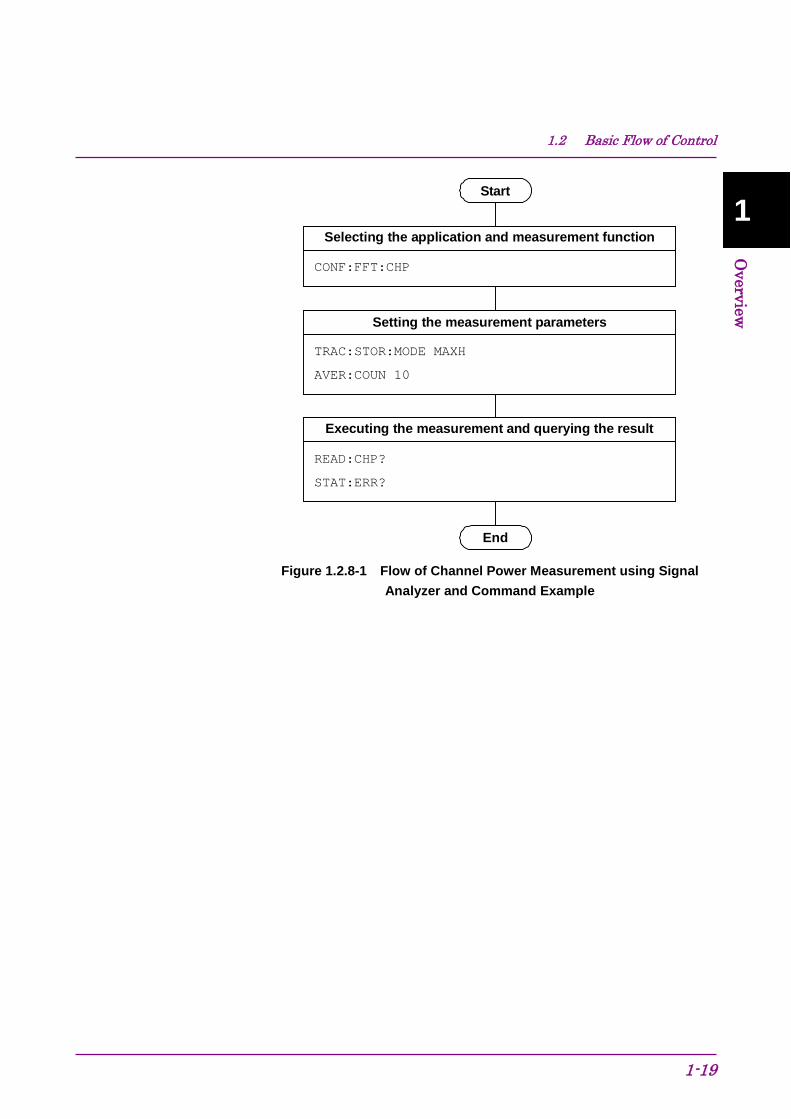
1.2.8 Channel Power Measurement The Channel Power measurement is basically executed in the following order:
(1) Selecting the application and measurement function Select either Signal Analyzer or Spectrum Analyzer as the application to execute the Channel Power measurement function. The application is switched to the selected one if the Channel Power measurement function is selected. The basic parameter values are applied to the selected application. Subsequently, only the commands/queries available in the selected application can be used.
(2) Setting the measurement parameters The following parameters apply only to the specific application selected.
(a) Trigger
(b) Time Length/Filter Type/Storage, etc. (in Signal Analyzer)
(c) Sweep Time/Filter Type/Storage, etc. (in Spectrum Analyzer)
(3) Executing the measurement and querying the result
(4) Setting the display contents This setting is for displaying the result on the screen. However, you do not need to perform the setting if you only query the result through remote control.
1.2 Basic Flow of Control
1-19
1
Overview
Start
End
Selecting the application and measurement function
CONF:FFT:CHP
TRAC:STOR:MODE MAXH
AVER:COUN 10
Executing the measurement and querying the result
READ:CHP?
STAT:ERR?
Setting the measurement parameters
Figure 1.2.8-1 Flow of Channel Power Measurement using Signal Analyzer and Command Example

Chapter 1 Overview
1-20
1.2.9 OBW (Occupied Bandwidth) Measurement The OBW measurement is basically executed in the following order:
(1) Selecting the application and measurement function Select either Signal Analyzer or Spectrum Analyzer as the application to execute the OBW measurement function. The application is switched to the selected one if the OBW measurement function is selected. The basic parameter values are applied to the selected application. Subsequently, only the commands/queries available in the selected application can be used.
(2) Setting the measurement parameters The following parameters apply only to the specific application selected.
(a) Trigger
(b) Method/N% Ratio/XdB Value, etc.
(3) Executing the measurement and querying the result
(4) Setting the display contents This setting is for displaying the result on the screen. However, you do not need to perform the setting if you only query the result through remote control.
Start
End
Selecting the application and measurement function
CONF:FFT:OBW
OBW:METH NPER
OBW:PERC 99.0
Executing the measurement and querying the result
READ:OBW?
STAT:ERR?
Setting the measurement parameters
Figure 1.2.9-1 Flow of OBW Measurement using Signal Analyzer and Command Example

1.2 Basic Flow of Control
1-21
1
Overview
1.2.10 SEM (Spectrum Emission Mask) Measurement The SEM measurement is basically executed in the following order:
(1) Selecting the measurement function The application is switched to the selected one if the SEM measurement function is selected. The basic parameter values are applied to the spectrum analyzer. Subsequently, only the commands/queries available in the selected application can be used.
Note: The SEM measurement function is enabled only in the Spectrum Analyzer.
(2) Setting the measurement parameters The following parameters apply only to the specific application selected.
(a) Trigger
(b) Storage, etc.
(3) Executing the measurement and querying the result
(4) Setting the display contents This setting is for displaying the result on the screen. However, you do not need to perform the setting if you only query the result through remote control.
Start
End
Selecting the measurement function
CONF:SWEP:SEM
TRIG:SOUR IMM
TRAC:STOR:MODE MAXH
AVER:COUN 10
Executing the measurement and querying the result
READ:SEM?
STAT:ERR?
Setting the measurement parameters
Figure 1.2.10-1 Flow of SEM Measurement using Spectrum Analyzer and Command Example
Chapter 1 Overview
1-22
1.2.11 Signal Analyzer/Spectrum Analyzer Switching There are the following two methods for switching from this application to Signal Analyzer/Spectrum Analyzer during remote control.
Note: For MS2830A: To switch to signal analyzer, the analysis bandwidth option 31.25 MHz or greater is required.
(1) Execute CONFigure[:FFT|SWEPt]:<measure> Basic parameters such as carrier frequency and input level (reference level) are applied to the selected application. Furthermore, a template is automatically set depending on the state of this application. There is no limitation on control of the selected application.
Note: This may be impossible depending on the application used and the selected measurement function.
Also, you can switch between Signal Analyzer and Spectrum Analyzer by using CONFigure:FFT|SWEPt:<measure>. In the same way, basic parameters such as carrier frequency and input level (reference level) and templates are applied. When switching back to control of the measurement application using CONFigure:<measure>, the basic parameters changed in Signal Analyzer and Spectrum Analyzer such as carrier frequency and input level (reference level) are also applied. Compared with method (2), you can shorten the execution time of the program, since you do not need to reset the basic parameter per a measurement function.
(2) Execute :INSTrument[:SELect] SIGANA|SPECT With this method, the parameter and template changes are not applied.
1.2 Basic Flow of Control
1-23
1
Overview
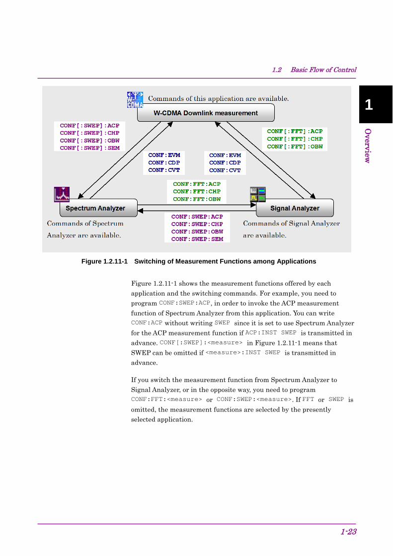
Figure 1.2.11-1 Switching of Measurement Functions among Applications
Figure 1.2.11-1 shows the measurement functions offered by each application and the switching commands. For example, you need to program CONF:SWEP:ACP, in order to invoke the ACP measurement function of Spectrum Analyzer from this application. You can write CONF:ACP without writing SWEP since it is set to use Spectrum Analyzer for the ACP measurement function if ACP:INST SWEP is transmitted in advance. CONF[:SWEP]:<measure> in Figure 1.2.11-1 means that SWEP can be omitted if <measure>:INST SWEP is transmitted in advance.
If you switch the measurement function from Spectrum Analyzer to Signal Analyzer, or in the opposite way, you need to program CONF:FFT:<measure> or CONF:SWEP:<measure>. If FFT or SWEP is omitted, the measurement functions are selected by the presently selected application.

Chapter 1 Overview
1-24
1.3 How to use the Native Mode In this instrument, types of syntax/format of the remote control commands are defined as “Language mode”. The language mode has two modes, SCPI and Native.
(1) SCPI Mode Processes commands conforming to the grammar/document format defined in SCPI (ver1999.0). In the SCPI mode, you can use the character string in long/short form format and can omit angled bracket ([ ]) definition character strings. On the Configuration screen, the SCPI mode is automatically set after transmitting command SYST:LANG SCPI.
(2) Native Mode Processes commands that are in this instrument’s own definition type. Unless otherwise specified, the character string of a command header is fixed. If a command of the application is only defined by SCPI mode, the character string converted by the conversion rule is a command in the Native mode. For programming, you cannot use the grammar of SCPI mode, such as character string in long/short form format and cannot omit any angled bracket ([ ]) definition character strings.
Note: The STATus:QUEStionable and STATus:OPERation registers cannot be used in the Native mode, even when the corresponding commands are converted to Native-mode commands according to the conversion rules. On the Configuration screen, the Native mode is automatically set after transmitting the command SYST:LANG NAT.

1.3 How to use the Native Mode
1-25
1
Overview
SCPI mode
Command definition AAAAaa:BBBBbb[:CCCCcc]:D|E <n>
Programming Examples: AAAAaa:BBBBbb:CCCCcc:D 0
AAAA:BBBB:CCCC:D 0
AAAA:BBBB:D 0
AAAA:BBBB:CCCC:E 0
Native mode (initial state)
Command definition (unique) VWXYZ1 <n>
Programming Example: VWXYZ 0
Command definition (converted to SCPI)
AAAA:BBBB:D <n>
Programming Example: AAAA:BBBB:D 0
SYST:LANG SCPI
SYST:LANG NAT
AAAA:BBBB:E 0
Figure 1.3-1 SCPI mode and Native mode

Chapter 1 Overview
1-26
This application is only defined as the commands of the SCPI mode. You need to follow the conversion rule below in order to control this application by using the Native mode.
Conversion rule [1] Delete the numeric parameter in the program header of an SCPI
command, and describe the argument corresponding to the numeric parameter as the first argument. If the argument can have only one numeric value and the argument can be omitted, omit it. Describe the argument if it cannot be omitted.
[2] Use the first one if multiple nodes can be selected.
[3] Delete those layers which can be deleted.
[4] Alter all long forms into short forms.
[5] Delete the colon mark (“:”) at the head. Example 1 Convert :CALCulate:MARKer[1]|2[:SET]:CENTer into a Native command. [1] Move the numeric parameter in the program header to the head of
the argument. :CALCulate:MARKer[1]|2[:SET]:CENTer
↓ :CALCulate:MARKer[:SET]:CENTer <integer>
(<integer> indicates an argument to which 1 or 2 is assigned.)
[2] Delete the layers that can be deleted. :CALCulate:MARKer[:SET]:CENTer <integer>
↓ :CALCulate:MARKer:CENTer <integer>
[3] Alter all long forms into short forms.
:CALCulate:MARKer:CENTer <integer>
↓ :CALC:MARK:CENT <integer>
[4] Delete the colon mark (“:”) at the head.
:CALC:MARK:CENT <integer>
↓ CALC:MARK:CENT <integer>

1.3 How to use the Native Mode
1-27
1
Overview
Example 2 Convert[:SENSe]:BPOWer|:TXPower[:STATe]? into a Native command. [1] Use the first node if multiple ones can be selected.
[:SENSe]:BPOWer|:TXPower[:STATe]?
↓ [:SENSe]:BPOWer[:STATe]?
[2] Delete the layers that can be deleted.
[:SENSe]:BPOWer[:STATe]?
↓ :BPOWer?
[3] Alter all long forms into short forms.
:BPOWer?
↓ :BPOW?
[4] Delete the colon mark (“:”) at the head.
:BPOW?
↓ BPOW?

Chapter 1 Overview
1-28
Example 3 To convert :FETCh:EVM[n]? into a Native-mode command. [1] Move the numeric parameter in the program header to the head of
the argument. :FETCh:EVM[n]? ↓ :FETCh:EVM? <integer>
(<integer> indicates a numeric value.)
[2] Alter all the long-formed characters into short-formed ones. :FETCh:EVM? <integer>
↓ :FETC:EVM? <integer>
[3] Delete the colon mark (“:”) at the head.
:FETC:EVM? <integer>
↓ FETC:EVM? <integer>
Set a numeric value to the argument.
:FETC:EVM? <integer>
↓ FETC:EVM? 1
1.4 Character Programs Available for Setting Numeric Program Data
1-29
1
Overview
1.4 Character Programs Available for Setting Numeric Program Data
The following character programs can be used for setting numeric program data (numeric parameter) and are applicable only when using the SCPI mode.
(1) DEFault When DEFault is specified for numeric program data, the initial value is set for the target parameter.
(2) MINimum
When MINimum is specified for numeric program data, the minimum value is set for the target parameter.
(3) MAXimum
When MAXimum is specified for numeric program data, the maximum value is set for the target parameter.
In this application, DEFault, MINimum, and MAXimum can be used for the following parameters:
<freq>
<real>
<integer>
<rel_power>
<rel_ampl>
<time>

Chapter 1 Overview
1-30.
Chapter 2 SCPI Device Message Details
2-1
2
SCPI Device M
essage Details
This chapter describes the detailed specifications of SCPI remote control commands for executing the functions of this application. The device messages are listed according to function. Refer to the “MS2690/MS2691/MS2692A and MS2830A/MS2840A/MS2850A Signal Analyzer Operation Manual (Mainframe Remote Control)” for detailed specifications of the IEEE488.2 common device messages and application common device messages.
2.1 Selecting applications .......................................................................................................... 2-8 2.1.1 Loading applications ............................................................................................................. 2-9
:SYSTem:APPLication:LOAD WCDMADL ................................................................................ 2-9 :SYSTem:APPLication:UNLoad WCDMADL ............................................................................. 2-9
2.1.2 Selecting applications ......................................................................................................... 2-10 :INSTrument[:SELect] WCDMADL|CONFIG ........................................................................... 2-10 :INSTrument[:SELect]? ............................................................................................................ 2-11 :INSTrument:SYSTem WCDMADL,[ACTive]|INACtive|MINimum ........................................... 2-12 :INSTrument:SYSTem? WCDMADL ....................................................................................... 2-13
2.1.3 Initialization ......................................................................................................................... 2-14 :INSTrument:DEFault .............................................................................................................. 2-14 :SYSTem:PRESet .................................................................................................................... 2-14
2.2 Settings parameters .......................................................................................................... 2-15 2.2.1 Carrier Frequency ............................................................................................................... 2-16
[:SENSe]:FREQuency:CENTer <freq> .................................................................................... 2-16 [:SENSe]:FREQuency:CENTer? ............................................................................................. 2-17
2.2.2 Input Level .......................................................................................................................... 2-18 [:SENSe]:POWer[:RF]:RANGe:ILEVel <real> ......................................................................... 2-18 [:SENSe]:POWer[:RF]:RANGe:ILEVel? .................................................................................. 2-19
2.2.3 Reference Level .................................................................................................................. 2-20 :DISPlay:WINDow[1]:TRACe:Y[:SCALe]:RLEVel <real> ........................................................ 2-20 :DISPlay:WINDow[1]:TRACe:Y[:SCALe]:RLEVel? .................................................................. 2-21
2.2.4 Level Offset ......................................................................................................................... 2-22 :DISPlay:WINDow[1]:TRACe:Y[:SCALe]:RLEVel:OFFSet <rel_power> ................................. 2-22 :DISPlay:WINDow[1]:TRACe:Y[:SCALe]:RLEVel:OFFSet? .................................................... 2-22
2.2.5 Level Offset State ............................................................................................................... 2-23 :DISPlay:WINDow[1]:TRACe:Y[:SCALe]:RLEVel:OFFSet:STATe OFF|ON|0|1 ..................... 2-23 :DISPlay:WINDow[1]:TRACe:Y[:SCALe]:RLEVel:OFFSet:STATe? ........................................ 2-23
2.2.6 Pre Amp .............................................................................................................................. 2-24 [:SENSe]:POWer[:RF]:GAIN[:STATe] OFF|ON|0|1 ................................................................. 2-24 [:SENSe]:POWer[:RF]:GAIN[:STATe]? ................................................................................... 2-25
2.2.7 Auto Range ......................................................................................................................... 2-26 [:SENSe]:POWer[:RF]:RANGe:AUTO ONCE ......................................................................... 2-26
2.3 Setting of System Parameters ........................................................................................... 2-27 2.3.1 Scrambling Code ................................................................................................................ 2-29
[:SENSe]:EVM:SYNC:SCRamble <integer> ........................................................................... 2-29 [:SENSe]:EVM:SYNC:SCRamble? .......................................................................................... 2-30 [:SENSe]:RHO:SYNC:SCRamble[:BTS] <integer> ................................................................. 2-30 [:SENSe]:RHO:SYNC:SCRamble[:BTS]? ............................................................................... 2-31
Chapter 2 SCPI Device Message Details
2-2
[:SENSe]:CDPower:SYNC:SCRamble[:BTS] <integer> .......................................................... 2-31 [:SENSe]:CDPower:SYNC:SCRamble[:BTS]? ........................................................................ 2-31 [:SENSe]:PCONtrol:SYNC:SCRamble[:BTS] <integer> .......................................................... 2-32 [:SENSe]:PCONtrol:SYNC:SCRamble[:BTS]? ........................................................................ 2-32
2.3.2 Origin Offset ........................................................................................................................ 2-33 [:SENSe]:EVM:ORIGin INCLude|EXCLude............................................................................. 2-33 [:SENSe]:EVM:ORIGin? .......................................................................................................... 2-33 :CALCulate:RHO:IQOFfset:INCLude OFF|ON|0|1 .................................................................. 2-34 :CALCulate:RHO:IQOFfset:INCLude?..................................................................................... 2-34
2.3.3 Active Code Threshold ....................................................................................................... 2-35 :CALCulate:EVM:ASET:THReshold <rel_ampl> ..................................................................... 2-35 :CALCulate:EVM:ASET:THReshold? ...................................................................................... 2-36 :CALCulate:RHO:ASET:THReshold <rel_ampl> ..................................................................... 2-37 :CALCulate:RHO:ASET:THReshold? ...................................................................................... 2-37 :CALCulate:CDPower:ASET:THReshold <rel_ampl> ............................................................. 2-38 :CALCulate:CDPower:ASET:THReshold? .............................................................................. 2-38
2.3.4 Scrambling Code Synchronization...................................................................................... 2-39 [:SENSe]:EVM:SYNC:SCSYnc SCH|UDEFined ..................................................................... 2-39 [:SENSe]:EVM:SYNC:SCSYnc? .............................................................................................. 2-39
2.3.5 Frame Sync Code Type ...................................................................................................... 2-40 [:SENSe]:EVM:SYNC:FSCType CPICh|UDEFined ................................................................. 2-40 [:SENSe]:EVM:SYNC:FSCType? ............................................................................................ 2-40
2.3.6 Frame Sync Spreading Factor ............................................................................................ 2-41 [:SENSe]:EVM:SYNC:FSSFactor 4|8|16|32|64|128|256|512 .................................................. 2-41 [:SENSe]:EVM:SYNC:FSSFactor? .......................................................................................... 2-42
2.3.7 Frame Sync Code Number ................................................................................................. 2-43 [:SENSe]:EVM:SYNC:FSCNumber <integer> ......................................................................... 2-43 [:SENSe]:EVM:SYNC:FSCNumber? ....................................................................................... 2-43
2.3.8 Channel Detection .............................................................................................................. 2-44 [:SENSe]:EVM:CDETection[:BTS]
AUTO|TM1D16|TM1D32|TM1D64|TM2|TM3D16|TM3D32|TM4|TM4CP|TM5H2|TM5H4 |TM5H8|TM6|UDEF|UDEF2 .......................................................................................... 2-44
[:SENSe]:EVM:CDETection[:BTS]? ......................................................................................... 2-45 [:SENSe]:RHO:SBOundary[:BTS]
AUTO|TM1D16|TM1D32|TM1D64|TM2|TM3D16|TM3D32|TM4|TM4CP|TM5H2|TM5H4 |TM5H8|TM6|UDEF|UDEF2 .......................................................................................... 2-46
[:SENSe]:RHO:SBOundary[:BTS]? ........................................................................................ 2-47 [:SENSe]:EVM:CDETection:UDEFined:FSELect .................................................................... 2-48 [:SENSe]:EVM:CDETection:UDEFined:FSELect? .................................................................. 2-51 [:SENSe]:EVM:CDETection:UDEFined2:LIST[:BTS] <SF1>,<CH1>,<Modulation
Scheme1>,[<SF2>,<CH2>,<Modulation Scheme2>],,,,,,[<SF256>,<CH256>, <Modulation Scheme256>] ............................................................................................ 2-52
[:SENSe]:EVM:CDETection:UDEFined2:LIST[:BTS]? ............................................................ 2-53 :MMEMory:MOVE:CCONfiguration <filename>,<apl_name>,<device> .................................. 2-54 :MMEMory:COPY:CCONfiguration <filename>,<apl_name>,<device> .................................. 2-55 :MMEMory:DELete:CCONfiguration <filename>,<apl_name>,<device> ................................ 2-56 :MMEMory:PROTection:CCONfiguration[:STATe] <filename>,ON|OFF|0|1,<apl_name>,
<device> ........................................................................................................................ 2-57 :MMEMory:PROTection:CCONfiguration[:STATe]? <filename>,<apl_name>,<device> ........ 2-58
Chapter 2 SCPI Device Message Details
2-3
2
SCPI Device M
essage Details
MMEMory:CATalog:CCONfiguration? <apl_name>,<device> ................................................ 2-59 2.3.9 PICH CH Number ............................................................................................................... 2-60
[:SENSe]:EVM:PICH:CCODe <integer> .................................................................................. 2-60 [:SENSe]:EVM:PICH: CCODe? ............................................................................................... 2-60
2.3.10 SCH Interference of Relative CDE ..................................................................................... 2-61 [:SENSe]:EVM:SINTerference INCLude|EXCLude ................................................................. 2-61 [:SENSe]:EVM:SINTerference? ............................................................................................... 2-61
2.3.11 Peak Relative CDE Detection Mode ................................................................................... 2-62 [:SENSe]:EVM:PRDM SLOT|MINT ......................................................................................... 2-62 [:SENSe]:EVM:PRDM? ............................................................................................................ 2-62
2.4 Utility Functions ................................................................................................................. 2-63 2.4.1 Erase Warm Up Message ................................................................................................... 2-64
:DISPlay:ANNotation:WUP:ERASe ......................................................................................... 2-64 2.4.2 Display Title ........................................................................................................................ 2-65
:DISPlay:ANNotation:TITLe[:STATe] OFF|ON|0|1 .................................................................. 2-65 :DISPlay:ANNotation:TITLe[:STATe]? ..................................................................................... 2-65
2.4.3 Title Entry ............................................................................................................................ 2-66 :DISPlay:ANNotation:TITLe:DATA <string> ............................................................................ 2-66 :DISPlay:ANNotation:TITLe:DATA? ........................................................................................ 2-66
2.5 Common Measurement Function ...................................................................................... 2-67 2.5.1 Measurement and Control .................................................................................................. 2-68
:INITiate:CONTinuous OFF|ON|0|1 ......................................................................................... 2-68 :INITiate:CONTinuous? ........................................................................................................... 2-68 :INITiate:MODE:CONTinuous .................................................................................................. 2-69 :INITiate:MODE:SINGle ........................................................................................................... 2-69 :INITiate[:IMMediate]................................................................................................................ 2-69 :CONFigure? ............................................................................................................................ 2-70
2.5.2 Trigger Switch ..................................................................................................................... 2-71 :TRIGger[:SEQuence][:STATe] OFF|ON|0|1 ........................................................................... 2-71 :TRIGger[:SEQuence][:STATe]? ............................................................................................. 2-71
2.5.3 Trigger Source .................................................................................................................... 2-72 :TRIGger[:SEQuence]:SOURce EXTernal[1|2]|EXT2|IMMediate|SG ..................................... 2-72 :TRIGger[:SEQuence]:SOURce? ............................................................................................ 2-73 :TRIGger:RHO[:SEQuence]:SOURce EXTernal[1|2]|EXT2|IMMediate|SG ............................ 2-74 :TRIGger:RHO[:SEQuence]:SOURce? ................................................................................... 2-75 :TRIGger:CDPower[:SEQuence]:SOURce EXTernal[1|2]|EXT2|IMMediate|SG ..................... 2-75 :TRIGger:CDPower[:SEQuence]:SOURce? ............................................................................ 2-75
2.5.4 Trigger Slope ...................................................................................................................... 2-76 :TRIGger[:SEQuence]:SLOPe POSitive|NEGative ................................................................. 2-76 :TRIGger[:SEQuence]:SLOPe? ............................................................................................... 2-77 :TRIGger[:SEQuence]:EXTernal[1|2]:SLOPe POSitive|NEGative .......................................... 2-78 :TRIGger[:SEQuence]:EXTernal[1|2]:SLOPe? ........................................................................ 2-78
2.5.5 Trigger Delay ...................................................................................................................... 2-79 :TRIGger[:SEQuence]:DELay <time> ...................................................................................... 2-79 :TRIGger[:SEQuence]:DELay? ................................................................................................ 2-80 :TRIGger[:SEQuence]:EXTernal[1|2]:DELay <time> ............................................................... 2-81 :TRIGger[:SEQuence]:EXTernal[1|2]:DELay? ......................................................................... 2-81
2.6 ACP/Channel Power/OBW/SEM measurement function .................................................. 2-82 :CONFigure[:FFT|SWEPt]:ACP ............................................................................................... 2-83
Chapter 2 SCPI Device Message Details
2-4
:CONFigure[:FFT|SWEPt]:CHPower ....................................................................................... 2-84 :CONFigure[:FFT|SWEPt]:OBWidth ........................................................................................ 2-85 :CONFigure[:SWEPt]:SEMask ................................................................................................. 2-85 [:SENSe]:ACPower:INSTrument[:SELect] FFT|SWEPt .......................................................... 2-86 [:SENSe]:ACPower:INSTrument[:SELect]? ............................................................................. 2-87 [:SENSe]:CHPower:INSTrument[:SELect] FFT|SWEPt .......................................................... 2-88 [:SENSe]:CHPower:INSTrument[:SELect]? ............................................................................ 2-89 [:SENSe]:OBWidth:INSTrument[:SELect] FFT|SWEPt ........................................................... 2-90 [:SENSe]:OBWidth:INSTrument[:SELect]? ............................................................................. 2-91 [:SENSe]:ASETting:CATT OFF|ON|0|1 ................................................................................... 2-92 [:SENSe]:ASETting:CATT? ..................................................................................................... 2-93
2.7 Modulation Measurement Function ................................................................................... 2-94 2.7.1 Measure ............................................................................................................................ 2-107
:CONFigure:EVM ................................................................................................................... 2-107 :CONFigure:RHO ................................................................................................................... 2-107 :INITiate:EVM ......................................................................................................................... 2-108 :INITiate:RHO ........................................................................................................................ 2-108 :FETCh:EVM[n]? .................................................................................................................... 2-109 :FETCh:RHO[n]? .................................................................................................................... 2-109 :READ:EVM[n]? ..................................................................................................................... 2-110 :READ:RHO[n]? ..................................................................................................................... 2-110 :MEASure:EVM[n]? ................................................................................................................ 2-111 :MEASure:RHO[n]?................................................................................................................ 2-111
2.7.2 Starting Slot Number ........................................................................................................ 2-112 :CALCulate:EVM:SWEep:STARt <integer> .......................................................................... 2-112 :CALCulate:EVM:SWEep:STARt? ......................................................................................... 2-113 :CALCulate:RHO:SWEep:OFFSet <integer> ........................................................................ 2-114 :CALCulate:RHO:SWEep:OFFSet? ....................................................................................... 2-114
2.7.3 Measurement Interval ....................................................................................................... 2-115 :CALCulate:EVM:SWEep:INTerval <integer> ....................................................................... 2-115 :CALCulate:EVM:SWEep:INTerval? ...................................................................................... 2-115
2.7.4 Trace Mode ....................................................................................................................... 2-116 :DISPlay:EVM[:VIEW][:SELect] EVM|MAGNitude|PHASe|SUMMary ................................ 2-116 :DISPlay:EVM[:VIEW][:SELect]? ........................................................................................... 2-116
2.7.5 Target Slot Number .......................................................................................................... 2-117 :DISPlay:EVM[:VIEW]:SLOT <integer> ................................................................................. 2-117 :DISPlay:EVM[:VIEW]:SLOT? ............................................................................................... 2-118
2.7.6 Scale – EVM ..................................................................................................................... 2-119 :DISPlay:EVM[:VIEW]:WINDow2:TRACe:Y[:SCALe]:RLEVel 5|10|20|50............................. 2-119 :DISPlay:EVM[:VIEW]:WINDow2:TRACe:Y[:SCALe]:RLEVel? ............................................ 2-120
2.7.7 Scale – Magnitude Error ................................................................................................... 2-121 :DISPlay:EVM[:VIEW]:WINDow3:TRACe:Y[:SCALe]:RLEVel 5|10|20|50............................. 2-121 :DISPlay:EVM[:VIEW]:WINDow3:TRACe:Y[:SCALe]:RLEVel? ............................................ 2-122
2.7.8 Scale – Phase Error .......................................................................................................... 2-123 :DISPlay:EVM[:VIEW]:WINDow4:TRACe:Y[:SCALe]:RLEVel 5|10|20|50............................. 2-123 :DISPlay:EVM[:VIEW]:WINDow4:TRACe:Y[:SCALe]:RLEVel? ............................................ 2-124
2.7.9 Storage Mode ................................................................................................................... 2-125 [:SENSe]:EVM:AVERage[:STATe] OFF|ON|AMAXimum|0|1|2 ............................................. 2-125 [:SENSe]:EVM:AVERage[:STATe]? ...................................................................................... 2-126
Chapter 2 SCPI Device Message Details
2-5
2
SCPI Device M
essage Details
[:SENSe]:RHO:AVERage[:STATe] OFF|ON|AMAXimum|0|1|2 ............................................ 2-127 [:SENSe]:RHO:AVERage[:STATe]? ...................................................................................... 2-127
2.7.10 Storage Count ................................................................................................................... 2-128 [:SENSe]:EVM:AVERage:COUNt <integer> ......................................................................... 2-128 [:SENSe]:EVM:AVERage:COUNt? ........................................................................................ 2-129 [:SENSe]:RHO:AVERage:COUNt <integer> ......................................................................... 2-130 [:SENSe]:RHO:AVERage:COUNt? ........................................................................................ 2-130
2.7.11 Display Page ..................................................................................................................... 2-131 :DISPlay:EVM[:VIEW]:WINDow7:PAGE:NUMBer <integer> ................................................ 2-131 :DISPlay:EVM[:VIEW]:WINDow7:PAGE:NUMBer? ............................................................... 2-131
2.7.12 Marker – On/Off ................................................................................................................ 2-132 :CALCulate:EVM:MARKer[:STATe] OFF|ON|0|1 .................................................................. 2-132 :CALCulate:EVM:MARKer[:STATe]? ..................................................................................... 2-132
2.7.13 Active Trace ...................................................................................................................... 2-133 :CALCulate:EVM:MARKer:ACTive CONStellation|BOTTom ................................................. 2-133 :CALCulate:EVM:MARKer:ACTive? ...................................................................................... 2-133
2.7.14 Chip Number ..................................................................................................................... 2-134 :CALCulate:EVM:MARKer:CHIP <integer> ........................................................................... 2-134 :CALCulate:EVM:MARKer:CHIP? ......................................................................................... 2-135
2.7.15 Marker Value..................................................................................................................... 2-136 :CALCulate:EVM:MARKer:X? ................................................................................................ 2-136 :CALCulate:EVM:MARKer:Y? ................................................................................................ 2-137
2.8 Code Domain measurement function .............................................................................. 2-138 2.8.1 Measure ............................................................................................................................ 2-145
:CONFigure:CDPower ........................................................................................................... 2-145 :INITiate:CDPower ................................................................................................................. 2-145 :FETCh:CDPower[n]? ............................................................................................................ 2-146 :READ:CDPower[n]?.............................................................................................................. 2-146 :MEASure:CDPower[n]? ........................................................................................................ 2-147
2.8.2 Starting Slot Number ........................................................................................................ 2-148 :CALCulate:CDPower:SWEep:STARt|OFFSet <integer> ..................................................... 2-148 :CALCulate:CDPower:SWEep:STARt|OFFSet? ................................................................... 2-148
2.8.3 Measurement Interval ....................................................................................................... 2-149 :CALCulate:CDPower:SWEep:INTerval|TIME <integer> ...................................................... 2-149 :CALCulate:CDPower:SWEep:INTerval|TIME? .................................................................... 2-149
2.8.4 Code Number.................................................................................................................... 2-150 :CALCulate:CDPower:CODE <integer> ................................................................................ 2-150 :CALCulate:CDPower:CODE? ............................................................................................... 2-150
2.8.5 Trace Mode ....................................................................................................................... 2-151 :DISPlay:CDPower[:VIEW][:SELect] CONStellation|EVM|MAGNitude|PHASe |CPOWer .... 2-151 :DISPlay:CDPower[:VIEW][:SELect]?.................................................................................... 2-152
2.8.6 Code Domain Trace .......................................................................................................... 2-153 :DISPlay:CDPower[:VIEW]:CDOMain[:SELect] POWer|ERRor ............................................ 2-153 :DISPlay:CDPower[:VIEW]:CDOMain[:SELect]? ................................................................... 2-153
2.8.7 Target Slot Number .......................................................................................................... 2-154 :DISPlay:CDPower[:VIEW]:SLOT <integer> ......................................................................... 2-154 :DISPlay:CDPower[:VIEW]:SLOT? ........................................................................................ 2-154
2.8.8 Scale – Code Domain Power ............................................................................................ 2-155 :DISPlay:CDPower[:VIEW]:WINDow5:TRACe:Y[:SCALe]:RLEVel 20|40|60|80 ................... 2-155

Chapter 2 SCPI Device Message Details
2-6
:DISPlay:CDPower[:VIEW]:WINDow5:TRACe:Y[:SCALe]:RLEVel? ..................................... 2-156 2.8.9 Scale – Code Domain Error .............................................................................................. 2-157
:DISPlay:CDPower[:VIEW]:WINDow6:TRACe:Y[:SCALe]:RLEVel 20|40|60|80 ................... 2-157 :DISPlay:CDPower[:VIEW]:WINDow6:TRACe:Y[:SCALe]:RLEVel? ..................................... 2-158
2.8.10 Scale – EVM vs Symbol ................................................................................................... 2-159 :DISPlay:CDPower[:VIEW]:WINDow2:TRACe:Y[:SCALe]:RLEVel 5|10|20|50 ..................... 2-159 :DISPlay:CDPower[:VIEW]:WINDow2:TRACe:Y[:SCALe]:RLEVel? ..................................... 2-160
2.8.11 Scale – Magnitude Error vs Symbol ................................................................................. 2-161 :DISPlay:CDPower[:VIEW]:WINDow3:TRACe:Y[:SCALe]:RLEVel 5|10|20|50 ..................... 2-161 :DISPlay:CDPower[:VIEW]:WINDow3:TRACe:Y[:SCALe]:RLEVel? ..................................... 2-162
2.8.12 Scale – Phase Error vs Symbol ........................................................................................ 2-163 :DISPlay:CDPower[:VIEW]:WINDow4:TRACe:Y[:SCALe]:RLEVel 5|10|20|50 ..................... 2-163 :DISPlay:CDPower[:VIEW]:WINDow4:TRACe:Y[:SCALe]:RLEVel? ..................................... 2-164
2.8.13 Scale – Code Power vs Symbol ....................................................................................... 2-165 :DISPlay:CDPower[:VIEW]:WINDow7:TRACe:Y[:SCALe]:RLEVel 20|40|60|80 ................... 2-165 :DISPlay:CDPower[:VIEW]:WINDow7:TRACe:Y[:SCALe]:RLEVel? ..................................... 2-166
2.8.14 Marker – On/Off ................................................................................................................ 2-167 :CALCulate:CDPower:MARKer[:STATe] OFF|ON|0|1 ........................................................... 2-167 :CALCulate:CDPower:MARKer[:STATe]? ............................................................................. 2-167
2.8.15 Marker Number ................................................................................................................. 2-168 :CALCulate:CDPower:MARKer:SYMBol <integer> ............................................................... 2-168 :CALCulate:CDPower:MARKer:SYMBol? ............................................................................. 2-168
2.8.16 Marker Value..................................................................................................................... 2-169 :CALCulate:CDPower:MARKer:X? ........................................................................................ 2-169 :CALCulate:CDPower:MARKer:Y? ........................................................................................ 2-170 :CALCulate:CDPower:MARKer:Y:CDOMain? ....................................................................... 2-171 :CALCulate:CDPower:MARKer:Y:CDOMain:CPOWer? ........................................................ 2-171 :CALCulate:CDPower:MARKer:Y:CDOMain:CERRor? ......................................................... 2-172 :CALCulate:CDPower:MARKer:Y:CDOMain:SFACtor? ........................................................ 2-172 :CALCulate:CDPower:MARKer:Y:CDOMain:CCODe? ......................................................... 2-173 :CALCulate:CDPower:MARKer:Y:CDOMain:MODulation? ................................................... 2-173
2.9 Code vs Time measurement function ............................................................................. 2-174 2.9.1 Measure ............................................................................................................................ 2-182
:CONFigure:CVTime .............................................................................................................. 2-182 :INITiate:CVTime ................................................................................................................... 2-182 :FETCh:CVTime[n]?............................................................................................................... 2-183 :READ:CVTime[n]? ................................................................................................................ 2-183 :MEASure:CVTime[n]? .......................................................................................................... 2-184
2.9.2 Measurement Interval ....................................................................................................... 2-185 :CALCulate:CVTime:SWEep:INTerval <integer> .................................................................. 2-185 :CALCulate:CVTime:SWEep:INTerval? ................................................................................ 2-185
2.9.3 Code vs Time Target Code ............................................................................................... 2-186 :CALCulate:CVTime:CODE <integer> ................................................................................... 2-186 :CALCulate:CVTime:CODE? ................................................................................................. 2-186
2.9.4 Set Marker Number to Target Code ................................................................................. 2-187 :CALCulate:CVTime:STCode ................................................................................................ 2-187
2.9.5 Trace Mode ....................................................................................................................... 2-188 :DISPlay:CVTime[:VIEW][:SELect] CDPower|CDError ......................................................... 2-188 :DISPlay:CVTime[:VIEW][:SELect]? ...................................................................................... 2-188

Chapter 2 SCPI Device Message Details
2-7
2
SCPI Device M
essage Details
2.9.6 Scale – Code vs Time ....................................................................................................... 2-189 :DISPlay:CVTime[:VIEW]:WINDow8:TRACe:Y[:SCALe]:RLEVel 20|40|60|80 ..................... 2-189 :DISPlay:CVTime[:VIEW]:WINDow8:TRACe:Y[:SCALe]:RLEVel? ....................................... 2-190
2.9.7 Scale – Code Domain Power ............................................................................................ 2-191 :DISPlay:CVTime[:VIEW]:WINDow5:TRACe:Y[:SCALe]:RLEVel 20|40|60|80 ..................... 2-191 :DISPlay:CVTime[:VIEW]:WINDow5:TRACe:Y[:SCALe]:RLEVel? ....................................... 2-192
2.9.8 Scale – Code Domain Error .............................................................................................. 2-193 :DISPlay:CVTime[:VIEW]:WINDow6:TRACe:Y[:SCALe]:RLEVel 20|40|60|80 ..................... 2-193 :DISPlay:CVTime[:VIEW]:WINDow6:TRACe:Y[:SCALe]:RLEVel? ....................................... 2-194
2.9.9 Scale – Code vs Time Scale Offset .................................................................................. 2-195 :DISPlay:CVTime[:VIEW]:WINDow8:TRACe:Y[:SCALe]:RLEVel:OFFSet <rel_power> ...... 2-195 :DISPlay:CVTime[:VIEW]:WINDow8:TRACe:Y[:SCALe]:RLEVel:OFFSet? .......................... 2-196
2.9.10 Marker – On/Off ................................................................................................................ 2-197 :CALCulate:CVTime:MARKer[:STATe] OFF|ON|0|1 ............................................................. 2-197 :CALCulate:CVTime:MARKer[:STATe]?................................................................................ 2-197
2.9.11 Active Trace ...................................................................................................................... 2-198 :CALCulate:CVTime:MARKer:ACTive CVTime|BOTTom ..................................................... 2-198 :CALCulate:CVTime:MARKer:ACTive? ................................................................................. 2-198
2.9.12 Code vs Time Slot Number ............................................................................................... 2-199 :CALCulate:CVTime:SLOT <integer> .................................................................................... 2-199 :CALCulate:CVTime:SLOT? .................................................................................................. 2-199
2.9.13 Marker Value..................................................................................................................... 2-200 :CALCulate:CVTime:MARKer:Y:CVTime:MPOWer? ............................................................ 2-200 :CALCulate:CVTime:MARKer:Y:CVTime:CPOWer? ............................................................. 2-200 :CALCulate:CVTime:MARKer:Y:CVTime:SFACtor? ............................................................. 2-201 :CALCulate:CVTime:MARKer:Y:CVTime:CCODe? ............................................................... 2-201 :CALCulate:CVTime:MARKer:Y:CVTime:MODulation? ........................................................ 2-202
2.9.14 Bottom Graph Marker Number ......................................................................................... 2-203 :CALCulate:CVTime:MARKer:MNUMber <integer> .............................................................. 2-203 :CALCulate:CVTime:MARKer:MNUMber? ............................................................................ 2-203
2.9.15 Marker Value..................................................................................................................... 2-204 :CALCulate:CVTime:MARKer:Y:CDOMain? ......................................................................... 2-204 :CALCulate:CVTime:MARKer:Y:CDOMain:CPOWer? .......................................................... 2-204 :CALCulate:CVTime:MARKer:Y:CDOMain:CERRor? ........................................................... 2-205 :CALCulate:CVTime:MARKer:Y:CDOMain:SFACtor? ........................................................... 2-205 :CALCulate:CVTime:MARKer:Y:CDOMain:CCODe? ............................................................ 2-206 :CALCulate:CVTime:MARKer:Y:CDOMain:MODulation? ..................................................... 2-207
Chapter 2 SCPI Device Message Details
2-8
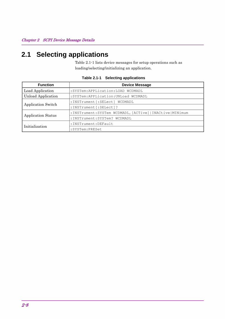
2.1 Selecting applications Table 2.1-1 lists device messages for setup operations such as loading/selecting/initializing an application.
Table 2.1-1 Selecting applications
Function Device Message Load Application :SYSTem:APPLication:LOAD WCDMADL
Unload Application :SYSTem:APPLication:UNLoad WCDMADL
Application Switch :INSTrument[:SELect] WCDMADL
:INSTrument[:SELect]?
Application Status :INSTrument:SYSTem WCDMADL,[ACTive]|INACtive|MINimum
:INSTrument:SYSTem? WCDMADL
Initialization :INSTrument:DEFault
:SYSTem:PRESet

2.1 Selecting applications
2-9
2
SCPI Device M
essage Details
2.1.1 Loading applications :SYSTem:APPLication:LOAD WCDMADL Load Application Function
This command loads the application.
Command :SYSTem:APPLication:LOAD WCDMADL
Details This function loads an installed application and registers it to the Application Switch menu. This function is available when the control-targeted application is Config.
Example of Use To load the application. INST CONFIG
SYST:APPL:LOAD WCDMADL
:SYSTem:APPLication:UNLoad WCDMADL Unload Application Function
This command exits the application.
Command :SYSTem:APPLication:UNLoad WCDMADL
Details This function exits the active application and deletes it from the Application Switch menu. This function is available when the control-targeted application is Config.
Example of Use To exit the application. INST CONFIG
SYST:APPL:UNL WCDMADL
Chapter 2 SCPI Device Message Details
2-10
2.1.2 Selecting applications :INSTrument[:SELect] WCDMADL|CONFIG Application Switch Function
This command selects the controlled application.
Command :INSTrument[:SELect] <apl_name>
Parameter <apl_name> Application
WCDMADL This application CONFIG Config
Details
To select a measurement function of Signal Analyzer or Spectrum Analyzer from this application, use the following commands: :CONFigure[:FFT|SWEPt]:ACP
:CONFigure[:FFT|SWEPt]:CHPower
:CONFigure[:FFT|SWEPt]:OBWidth
:CONFigure[:SWEPt]:SEMask
Example of Use To switch the control target to this application. INST WCDMADL

2.1 Selecting applications
2-11
2
SCPI Device M
essage Details
:INSTrument[:SELect]? Application Switch Query Function
This command queries the controlled application.
Query :INSTrument[:SELect]?
Response <apl_name>
Parameter <apl_name>Application
WCDMADL This application SIGANA Signal Analyzer SPECT Spectrum Analyzer CONFIG Config
Details WCDMADL is returned when a measurement function of this application, such as Modulation or Code Domain, is selected.
SIGANA or SPECT is returned when a measurement function of Signal Analyzer or Spectrum Analyzer, such as ACP, Channel Power, OBW, or SEM, is selected.
Example of Use To query the controlled application. INST?
> WCDMADL

Chapter 2 SCPI Device Message Details
2-12
:INSTrument:SYSTem WCDMADL,[ACTive]|INACtive|MINimum Application Switch And Window Status Function
This command selects the application to be controlled by specifying the window status.
Command :INSTrument:SYSTem <apl_name>,<window>
Parameter <apl_name> Application
WCDMADL This application SIGANA Signal Analyzer SPECT Spectrum Analyzer CONFIG Config
<window> Window status ACTive Active INACtive Inactive MINimum Minimized When omitted Active
Example of Use
To select this application with the window active. INST:SYST WCDMADL,ACT
2.1 Selecting applications
2-13
2
SCPI Device M
essage Details
:INSTrument:SYSTem? WCDMADL Application Switch And Window Status Query Function
This command queries the status of the specified application.
Query :INSTrument:SYSTem? <apl_name>
Response <status>,<window>
Parameter <apl_name> Application
WCDMADL This application SIGANA Signal Analyzer SPECT Spectrum Analyzer CONFIG Config
<status> Application status
CURR Executed and targeted for control RUN Executed but not targeted for control IDLE Loaded but not executed UNL Not loaded
<window> Window status
ACT Active INAC Inactive MIN Minimized NON Window not displayed
Example of Use
To query the status of this application. INST:SYST? WCDMADL
> CURR,ACT

Chapter 2 SCPI Device Message Details
2-14
2.1.3 Initialization :INSTrument:DEFault Preset Current Application Function
This command initializes the settings and status of the currently selected application.
Command :INSTrument:DEFault
Details The parameter of Signal Analyzer/Spectrum Analyzer is initialized, when the ACP/Channel Power/OBW/SEM measurement function is selected by the following commands after :INST:DEF has been sent by this application. :CONFigure[:FFT|SWEPt]:ACP :CONFigure[:FFT|SWEPt]:CHPower :CONFigure[:FFT|SWEPt]:OBWidth :CONFigure[:SWEPt]:SEMask
Example of Use To initialize the settings and status of the currently selected application. INST:DEF
:SYSTem:PRESet Preset Current Application Function
This command initializes the settings and status of the currently selected application.
Refer to :INSTrument:DEFault
Example of Use To initialize the settings and status of the currently selected application. SYST:PRES

2.2 Settings parameters
2-15
2
SCPI Device M
essage Details
2.2 Settings parameters Table 2.2-1 lists device messages for setting the parameters commonly applied to this application, such as frequency and level.
Table 2.2-1 Settings parameters
Parameter Device Message
Carrier Frequency [:SENSe]:FREQuency:CENTer <freq>
[:SENSe]:FREQuency:CENTer?
Input Level [:SENSe]:POWer[:RF]:RANGe:ILEVel <real>
[:SENSe]:POWer[:RF]:RANGe:ILEVel?
Reference Level (Remote only)
:DISPlay:WINDow[1]:TRACe:Y[:SCALe]:RLEVel <real>
:DISPlay:WINDow[1]:TRACe:Y[:SCALe]:RLEVel?
Level Offset :DISPlay:WINDow[1]:TRACe:Y[:SCALe]:RLEVel:OFFSet <rel_power>
:DISPlay:WINDow[1]:TRACe:Y[:SCALe]:RLEVel:OFFSet?
Level Offset State
:DISPlay:WINDow[1]:TRACe:Y[:SCALe]:RLEVel:OFFSet:STATe OFF|ON|0|1
:DISPlay:WINDow[1]:TRACe:Y[:SCALe]:RLEVel:OFFSet:STATe?
Pre-Amp State [:SENSe]:POWer[:RF]:GAIN[:STATe] OFF|ON|0|1
[:SENSe]:POWer[:RF]:GAIN[:STATe]?
Auto Range [:SENSe]:POWer[:RF]:RANGe:AUTO ONCE

Chapter 2 SCPI Device Message Details
2-16
2.2.1 Carrier Frequency [:SENSe]:FREQuency:CENTer <freq> Carrier Frequency Function
This command sets the carrier frequency of the measured signal.
Command [:SENSe]:FREQuency:CENTer <freq>
Parameter <freq> Carrier frequency
Range 30 MHz to the upper limit of the main unit Resolution 1 Hz Suffix codes HZ,KHZ,KZ,MHZ,MZ,GHZ,GZ
Hz is used when omitted. Default value 2110 MHz
Example of Use To set the carrier frequency to 1.945 GHz. FREQ:CENT 1.945GHZ

2.2 Settings parameters
2-17
2
SCPI Device M
essage Details
[:SENSe]:FREQuency:CENTer? Carrier Frequency Query Function
This command queries the carrier frequency of the measured signal.
Query [:SENSe]:FREQuency:CENTer?
Response <freq>
Parameter <freq> Carrier frequency
Range 30 MHz to the upper limit of the main unit Resolution 1 Hz
Value is returned in Hz units.
Example of Use To query the carrier frequency. FREQ:CENT?
> 1920000000

Chapter 2 SCPI Device Message Details
2-18
2.2.2 Input Level [:SENSe]:POWer[:RF]:RANGe:ILEVel <real> Input Level Function
This command sets the input level of RF signals.
Command [:SENSe]:POWer[:RF]:RANGe:ILEVel <real>
Parameter <real> Input level
Range (–60.00 + Level Offset) to (30.00 + Level Offset) dBm (when Pre Amp is Off) (–80.00 + Level Offset) to (10.00 + Level Offset) dBm (when Pre Amp is On) 0.01 dB
Resolution 0.01 dB Suffix codes DBM
dBm is used when omitted. Default value –10.00 dBm
Details The setting range when Pre Amp is Off is applied if the MS2690A/MS2691A/MS2692A-008 6 GHz Preamplifier, MS2830A-008 or MS2850A-068 Preamplifier (hereinafter referred to as “Option 008”) is not installed.
Example of Use To set the input level to –15.00 dBm. POW:RANG:ILEV –15.00

2.2 Settings parameters
2-19
2
SCPI Device M
essage Details
[:SENSe]:POWer[:RF]:RANGe:ILEVel? Input Level Query Function
This command queries the input level of RF signals.
Query [:SENSe]:POWer[:RF]:RANGe:ILEVel?
Parameter <real> Input level
Range (–60.00 + Level Offset) to (30.00 + Level Offset) dBm (when Pre Amp is Off) (–80.00 + Level Offset) to (10.00 + Level Offset) dBm (when Pre Amp is On)
Resolution 0.01 dB Value is returned in dBm units.
Example of Use To query the input level. POW:RANG:ILEV?
> –15.00

Chapter 2 SCPI Device Message Details
2-20
2.2.3 Reference Level :DISPlay:WINDow[1]:TRACe:Y[:SCALe]:RLEVel <real> Reference Level Function
This command sets the reference level for ACP, Channel Power, OBW, and SEM measurements.
Command :DISPlay:WINDow[1]:TRACe:Y[:SCALe]:RLEVel <real>
Parameter <real> Reference level value
Range (Minimum input level +10) to (Maximum input level +10) dBm
Resolution 0.01 dB Suffix codes DBM
dBm is used when omitted. Default value 0.00 dBm
Details Reference Level indicates the peak level of the input signal by using the internal parameter which is automatically calculated to Input Level and is not shown on the screen. This Reference level value is applied to the measurement function when fetching ACP/Channel Power/OBW/SEM measurement functions. The Input Level value is also changed when the Reference Level is changed.
Example of Use To set the reference level to 0.00 dBmV DISP:WIND:TRAC:Y:RLEV 0.00DBM
2.2 Settings parameters
2-21
2
SCPI Device M
essage Details
:DISPlay:WINDow[1]:TRACe:Y[:SCALe]:RLEVel? Reference Level Query Function
This command queries the reference level for ACP/Channel Power/OBW/SEM measurements.
Query :DISPlay:WINDow[1]:TRACe:Y[:SCALe]:RLEVel?
Parameter <real> Reference level value
Range (Minimum input level +10) to (Maximum input level +10) dBm
Resolution 0.01 dB Value is returned in dBm units.
Example of Use To query the reference level. DISP:WIND:TRAC:Y:RLEV?
> 0.00
Chapter 2 SCPI Device Message Details
2-22
2.2.4 Level Offset :DISPlay:WINDow[1]:TRACe:Y[:SCALe]:RLEVel:OFFSet <rel_power> Level Offset Function
This command sets the input level offset value.
Command :DISPlay:WINDow[1]:TRACe:Y[:SCALe]:RLEVel:OFFSet
<rel_power>
Parameter < rel_power > Offset value
Range –99.99 to 99.99 dB Resolution 0.01 dB Suffix codes DB
dB is used when omitted. Default value 0.00 dB
Example of Use To set the input level offset value to +10 dB DISP:WIND:TRAC:Y:RLEV:OFFS 10
:DISPlay:WINDow[1]:TRACe:Y[:SCALe]:RLEVel:OFFSet? Level Offset Query Function
This command sets the input level offset value.
Query :DISPlay:WINDow[1]:TRACe:Y[:SCALe]:RLEVel:OFFSet?
Parameter < rel_power > Offset value
Range –99.99 to 99.99 dB Resolution 0.01 dB
Example of Use To set the input level offset value. DISP:WIND:TRAC:Y:RLEV:OFFS?
> 10.00

2.2 Settings parameters
2-23
2
SCPI Device M
essage Details
2.2.5 Level Offset State :DISPlay:WINDow[1]:TRACe:Y[:SCALe]:RLEVel:OFFSet:STATe OFF|ON|0|1 Level Offset State Function
This command enables/disables the offset function of the input level.
Command :DISPlay:WINDow[1]:TRACe:Y[:SCALe]:RLEVel:OFFSet:STATe
<switch>
Parameter <switch> Input level offset On/Off
OFF|0 Disabled (Default value) ON|1 Enabled
Example of Use To enable the input level offset value. DISP:WIND:TRAC:Y:RLEV:OFFS:STAT ON
:DISPlay:WINDow[1]:TRACe:Y[:SCALe]:RLEVel:OFFSet:STATe? Level Offset State Query Function
This command queries the state of the input level offset function.
Query :DISPlay:WINDow[1]:TRACe:Y[:SCALe]:RLEVel:OFFSet:STATe?
Parameter <switch> Input level offset On/Off
0 Disabled 1 Enabled
Example of Use To query the state of the input level offset function. DISP:WIND:TRAC:Y:RLEV:OFFS:STAT?
> 1

Chapter 2 SCPI Device Message Details
2-24
2.2.6 Pre Amp [:SENSe]:POWer[:RF]:GAIN[:STATe] OFF|ON|0|1 Pre Amp Function
This command sets Pre-Amp to On/Off.
Command [:SENSe]:POWer[:RF]:GAIN[:STATe] <switch>
Parameter <switch> Pre-Amp On/Off
OFF|0 Off (Default value) ON|1 On
Details This command is invalid when the Option 008 is not installed.
Example of Use To set Pre-Amp to On. POW:GAIN ON

2.2 Settings parameters
2-25
2
SCPI Device M
essage Details
[:SENSe]:POWer[:RF]:GAIN[:STATe]? Pre Amp Query
Function
This command queries the state of Pre-Amp.
Query [:SENSe]:POWer[:RF]:GAIN[:STATe]?
Response <switch>
Parameter <switch> Pre-Amp On/Off
0 Off 1 On
Details
Off is returned when the Option 008 is not installed.
Example of Use To query the setting of Pre-Amp. POW:GAIN?
> 1

Chapter 2 SCPI Device Message Details
2-26
2.2.7 Auto Range [:SENSe]:POWer[:RF]:RANGe:AUTO ONCE Auto Range Function
This command executes Auto Range and adjust input level.
Command [:SENSe]:POWer[:RF]:RANGe:AUTO ONCE
Details This command is not available when the Replay function is executed.
Example of Use To execute Auto Range. POW:RANG:AUTO ONCE

2.3 Setting of System Parameters
2-27
2
SCPI Device M
essage Details
2.3 Setting of System Parameters Table 2.3-1 lists device messages for setting the parameters of the communication system to be measured. These parameters are commonly applied to Modulation, Code Domain, and Code vs Time measurements.
Table 2.3-1 Setting of System Parameters
Parameter Device Message
Scrambling Code
[:SENSe]:EVM:SYNC:SCRamble <integer>
[:SENSe]:EVM:SYNC:SCRamble?
[:SENSe]:RHO:SYNC:SCRamble[:BTS] <integer>
[:SENSe]:RHO:SYNC:SCRamble[:BTS]?
[:SENSe]:CDPower:SYNC:SCRamble[:BTS] <integer>
[:SENSe]:CDPower:SYNC:SCRamble[:BTS]?
[:SENSe]:PCONtrol:SYNC:SCRamble[:BTS] <integer>
[:SENSe]:PCONtrol:SYNC:SCRamble[:BTS]?
Origin Offset
[:SENSe]:EVM:ORIGin INCLude|EXCLude
[:SENSe]:EVM:ORIGin?
:CALCulate:RHO:IQOFfset:INCLude OFF|ON|0|1
:CALCulate:RHO:IQOFfset:INCLude?
Active Code Threshold
:CALCulate:EVM:ASET:THReshold <rel_ampl>
:CALCulate:EVM:ASET:THReshold?
:CALCulate:RHO:ASET:THReshold <rel_ampl>
:CALCulate:RHO:ASET:THReshold?
:CALCulate:CDPower:ASET:THReshold <rel_ampl>
:CALCulate:CDPower:ASET:THReshold?

Chapter 2 SCPI Device Message Details
2-28
Table 2.3-1 Setting of System Parameters (Cont’d)
Parameter Device Message Scrambling Code Synchronization
[:SENSe]:EVM:SYNC:SCSYnc SCH|UDEFined
[:SENSe]:EVM:SYNC:SCSYnc?
Frame Sync Code Type [:SENSe]:EVM:SYNC:FSCType CPICh|UDEFined
[:SENSe]:EVM:SYNC:FSCType?
Frame Sync Spreading Factor
[:SENSe]:EVM:SYNC:FSSFactor 4|8|16|32|64|128|256|512
[:SENSe]:EVM:SYNC:FSSFactor?
Frame Sync Code Number [:SENSe]:EVM:SYNC:FSCNumber <integer>
[:SENSe]:EVM:SYNC:FSCNumber?
Channel Detection
[:SENSe]:EVM:CDETection[:BTS] AUTO|TM1D16|TM1D32|TM1D64|TM2|TM3D16|TM3D32|TM4|TM4CP|TM5H2|TM5H4|TM5H8|TM6|UDEF|UDEF2
[:SENSe]:EVM:CDETection[:BTS]?
[:SENSe]:RHO:SBOundary[:BTS] AUTO|TM1D16|TM1D32|TM1D64|TM2|TM3D16|TM3D32|TM4|TM4CP|TM5H2|TM5H4|TM5H8|TM6|UDEF|UDEF2
[:SENSe]:RHO:SBOundary[:BTS]?
User Defined Select File [:SENSe]:EVM:CDETection:UDEFined:FSELect <filename>
User Defined2 For Remote
[:SENSe]:EVM:CDETection:UDEFined2:LIST[:BTS] <SF1>,<CH1>,<Modulation Scheme1>,[<SF2>,<CH2>,<Modulation Scheme2>],,,,,,[<SF256>,<CH256>,<Modulation Scheme256>]
Move Channel Configuration File (HDD to Device)
:MMEMory:MOVE:CCONfiguration <filename>,<apl_name>,<device>
Copy Channel Configuration File (Device to HDD)
:MMEMory:COPY:CCONfiguration <filename>,<apl_name>,<device>
Delete Channel Configuration File
:MMEMory:DELete:CCONfiguration <filename>,<apl_name>,<device>
Protect Channel Configuration File
:MMEMory:PROTection:CCONfiguration[:STATe] <filename>,ON|OFF|0|1,<apl_name>,<device>
:MMEMory:PROTection:CCONfiguration[:STATe]? <filename>, <apl_name>,<device>
Channel Configuration File List Query MMEMory:CATalog:CCONfiguration?
PICH CH Number [:SENSe]:EVM:PICH:CCODe <integer>
[:SENSe]:EVM:PICH:CCODe?
Peak Relative CDE Detection Mode
[:SENSe]:EVM:PRDM SLOT|MINT
[:SENSe]:EVM:PRDM?

2.3 Setting of System Parameters
2-29
2
SCPI Device M
essage Details
2.3.1 Scrambling Code [:SENSe]:EVM:SYNC:SCRamble <integer> Scrambling Code Function
This command sets the Scrambling Code when Scrambling Code Synchronization is set to User Defined.
Command [:SENSe]:EVM:SYNC:SCRamble <integer>
Parameter <integer> Scrambling Code
Range 0 to 8191 (0x0 to 0x1FFF) Resolution 1 Default value 0
Details Values with the prefix “#H” are settings value input hexadecimal.
Example of Use To set Scrambling Code to 1FFF. EVM:SYNC:SCR #H1FFF
Related Command This command has the same function as the following commands. [:SENSe]:RHO:SYNC:SCRamble[:BTS] <integer>
[:SENSe]:CDPower:SYNC:SCRamble[:BTS] <integer>
[:SENSe]:PCONtrol:SYNC:SCRamble[:BTS] <integer>
Chapter 2 SCPI Device Message Details
2-30
[:SENSe]:EVM:SYNC:SCRamble? Scrambling Code Query Function
This command queries the Scrambling Code. The response is always returned in a decimal value.
Query [:SENSe]:EVM:SYNC:SCRamble?
Response <integer>
Parameter <integer> Scrambling Code
Range 0 to 8191 (Decimal) Resolution 1
Example of Use
To query the Scrambling Code. EVM:SYNC:SCR?
> 8191
Related Command This command has the same function as the following commands. [:SENSe]:RHO:SYNC:SCRamble[:BTS]?
[:SENSe]:CDPower:SYNC:SCRamble[:BTS]?
[:SENSe]:PCONtrol:SYNC:SCRamble[:BTS]?
[:SENSe]:RHO:SYNC:SCRamble[:BTS] <integer> Scrambling Code Function
This command sets the Scrambling Code.
Refer to [:SENSe]:EVM:SYNC:SCRamble <integer>
Related Command This command has the same function as the following commands. [:SENSe]:EVM:SYNC:SCRamble <integer>
[:SENSe]:CDPower:SYNC:SCRamble[:BTS] <integer>
[:SENSe]:PCONtrol:SYNC:SCRamble[:BTS] <integer>

2.3 Setting of System Parameters
2-31
2
SCPI Device M
essage Details
[:SENSe]:RHO:SYNC:SCRamble[:BTS]? Scrambling Code Query Function
This command queries the Scrambling Code.
Refer to [:SENSe]:EVM:SYNC:SCRamble?
Related Command This command has the same function as the following commands. [:SENSe]:EVM:SYNC:SCRamble?
[:SENSe]:CDPower:SYNC:SCRamble[:BTS]?
[:SENSe]:PCONtrol:SYNC:SCRamble[:BTS]?
[:SENSe]:CDPower:SYNC:SCRamble[:BTS] <integer> Scrambling Code Function
This command sets the Scrambling Code.
Refer to [:SENSe]:EVM:SYNC:SCRamble <integer>
Related Command This command has the same function as the following commands. [:SENSe]:EVM:SYNC:SCRamble <integer>
[:SENSe]:RHO:SYNC:SCRamble[:BTS] <integer>
[:SENSe]:PCONtrol:SYNC:SCRamble[:BTS] <integer>
[:SENSe]:CDPower:SYNC:SCRamble[:BTS]? Scrambling Code Query Function
This command queries the Scrambling Code.
Refer to [:SENSe]:EVM:SYNC:SCRamble?
Related Command This command has the same function as the following commands. [:SENSe]:EVM:SYNC:SCRamble?
[:SENSe]:RHO:SYNC:SCRamble[:BTS]?
[:SENSe]:PCONtrol:SYNC:SCRamble[:BTS]?
Chapter 2 SCPI Device Message Details
2-32
[:SENSe]:PCONtrol:SYNC:SCRamble[:BTS] <integer> Scrambling Code Function
This command sets the Scrambling Code.
Refer to [:SENSe]:EVM:SYNC:SCRamble <integer>
Related Command This command has the same function as the following commands. [:SENSe]:EVM:SYNC:SCRamble <integer>
[:SENSe]:RHO:SYNC:SCRamble[:BTS] <integer>
[:SENSe]:CDPower:SYNC:SCRamble[:BTS] <integer>
[:SENSe]:PCONtrol:SYNC:SCRamble[:BTS]? Scrambling Code Query Function
This command queries the Scrambling Code.
Refer to [:SENSe]:EVM:SYNC:SCRamble?
Related Command This command has the same function as the following commands. [:SENSe]:EVM:SYNC:SCRamble?
[:SENSe]:RHO:SYNC:SCRamble[:BTS]?
[:SENSe]:CDPower:SYNC:SCRamble[:BTS]?

2.3 Setting of System Parameters
2-33
2
SCPI Device M
essage Details
2.3.2 Origin Offset [:SENSe]:EVM:ORIGin INCLude|EXCLude Origin Offset Function
This is used to set whether or not to include Origin Offset at EVM calculation.
Command [:SENSe]:EVM:ORIGin INCLude|EXCLude
Parameter <mode> Origin Offset
INCLude Includes Origin Offset (Default value) EXCLude Does not include Origin Offset
Example of Use
To include Origin Offset at EVM calculation. EVM:ORIG INCL
[:SENSe]:EVM:ORIGin? Origin Offset Query Function
This command queries the Origin Offset.
Query [:SENSe]:EVM:ORIGin?
Parameter <mode> Origin Offset
INCL Includes Origin Offset EXCL Does not include Origin Offset
Example of Use
To query the Origin Offset. EVM:ORIG?
> INCL

Chapter 2 SCPI Device Message Details
2-34
:CALCulate:RHO:IQOFfset:INCLude OFF|ON|0|1 Origin Offset Function
This is used to set whether or not to include Origin Offset at EVM calculation.
Command :CALCulate:RHO:IQOFfset:INCLude OFF|ON|0|1
Parameter <mode> Origin Offset
OFF|0 Does not include Origin Offset ON|1 Includes Origin Offset (Default value)
Example of Use
To set whether or not to include Origin Offset at EVM calculation. CALC:RHO:IQOF:INCL ON
:CALCulate:RHO:IQOFfset:INCLude? Origin Offset Query Function
This command queries the Origin Offset.
Query [:SENSe]:EVM:ORIGin?
Parameter <mode> Origin Offset
0 Does not include Origin Offset 1 Includes Origin Offset
Example of Use
To query the Origin Offset. CALC:RHO:IQOF:INCL?
> 1

2.3 Setting of System Parameters
2-35
2
SCPI Device M
essage Details
2.3.3 Active Code Threshold :CALCulate:EVM:ASET:THReshold <rel_ampl> Active Code Threshold Function
This command sets the Active Code Threshold.
This command can be set when Channel Detection is set to Auto.
Command :CALCulate:EVM:ASET:THReshold <rel_ampl>
Parameter <rel_ampl> Active Code Threshold
Range –40.0 to –10.0 dB Resolution 0.1 dB Suffix codes DB
dB is used when omitted. Default value –30.0 dB
Example of Use To set the Active Code Threshold to –20.0 dB. CALC:EVM:ASET:THR –20.0
Related Command This command has the same function as the following command. :CALCulate:RHO:ASET:THReshold <rel_ampl>

Chapter 2 SCPI Device Message Details
2-36
:CALCulate:EVM:ASET:THReshold? Active Code Threshold Query Function
This command queries the Active Code Threshold.
Query :CALCulate:EVM:ASET:THReshold?
Parameter <rel_ampl> Active Code Threshold
Range –40.0 to –10.0 dB Resolution 0.1 dB
Value is returned in dB units.
Example of Use To query the Active Code Threshold. CALC:EVM:ASET:THR?
> –20.0
Related Command This command has the same function as the following command. :CALCulate:RHO:ASET:THReshold?
2.3 Setting of System Parameters
2-37
2
SCPI Device M
essage Details
:CALCulate:RHO:ASET:THReshold <rel_ampl> Active Code Threshold Function
This command sets Active Code Threshold.
Refer to :CALCulate:EVM:ASET:THReshold <rel_ampl>
Related Command This command has the same function as the following command. :CALCulate:EVM:ASET:THReshold <rel_ampl>
:CALCulate:RHO:ASET:THReshold? Active Code Threshold Query Function
This command queries the Active Code Threshold.
Refer to :CALCulate:EVM:ASET:THReshold?
Related Command This command has the same function as the following command. :CALCulate:EVM:ASET:THReshold?

Chapter 2 SCPI Device Message Details
2-38
:CALCulate:CDPower:ASET:THReshold <rel_ampl> Active Code Threshold Function
This command sets the Active Code Threshold.
Refer to :CALCulate:EVM:ASET:THReshold <rel_ampl>
Related Command This command has the same function as the following command. :CALCulate:EVM:ASET:THReshold <rel_ampl>
:CALCulate:CDPower:ASET:THReshold? Active Code Threshold Query Function
This command queries the Active Code Threshold.
Refer to :CALCulate:EVM:ASET:THReshold?
Related Command This command has the same function as the following command. :CALCulate:EVM:ASET:THReshold?
2.3 Setting of System Parameters
2-39
2
SCPI Device M
essage Details
2.3.4 Scrambling Code Synchronization [:SENSe]:EVM:SYNC:SCSYnc SCH|UDEFined Scrambling Code Synchronization Function
This command sets Scrambling Code Synchronization.
Command [:SENSe]:EVM:SYNC:SCSYnc SCH|UDEFined
Parameter <mode> Scrambling Code Synchronization
SCH Scrambling Code is deduced from SCH information.
UDEFined User-specified Scrambling Code is used. Example of Use
To set Scrambling Code Synchronization to SCH. EVM:SYNC:SCSY SCH
[:SENSe]:EVM:SYNC:SCSYnc? Scrambling Code Synchronization Query Function
This command queries the Scrambling Code Synchronization.
Query [:SENSe]:EVM:SYNC:SCSYnc?
Parameter <mode> Scrambling Code Synchronization
SCH Scrambling Code is deduced from SCH information.
UDEF User-specified Scrambling Code is used. Example of Use
To query Scrambling Code Synchronization. EVM:SYNC:SCSY?
> SCH
Chapter 2 SCPI Device Message Details
2-40
2.3.5 Frame Sync Code Type [:SENSe]:EVM:SYNC:FSCType CPICh|UDEFined Frame Sync Code Type Function
This command sets the Frame Sync Code Type.
This command can be set when Channel Detection is set to Auto.
Command [:SENSe]:EVM:SYNC:FSCType CPICh|UDEFined
Parameter <mode> Frame Sync Code Type
CPICh P-CPICH is used for synchronization. UDEFined User-specified channel is used for
synchronization. Example of Use
To set Frame Sync Code Type to P-CPICH. EVM:SYNC:FSCT CPIC
[:SENSe]:EVM:SYNC:FSCType? Frame Sync Code Type Query Function
This command queries the Frame Sync Code Type.
Command [:SENSe]:EVM:SYNC:FSCType?
Parameter <mode> Frame Sync Code Type
CPIC P-CPICH is used for synchronization. UDEF User-specified channel is used for
synchronization. Example of Use
To query the Frame Sync Code Type. EVM:SYNC:FSCT?
> CPIC

2.3 Setting of System Parameters
2-41
2
SCPI Device M
essage Details
2.3.6 Frame Sync Spreading Factor [:SENSe]:EVM:SYNC:FSSFactor 4|8|16|32|64|128|256|512 Frame Sync Spreading Factor Function
This command sets the Frame Sync Spreading Factor when Frame Sync Code Type is set to User Defined.
This command can be set when Channel Detection is set to Auto.
Command [:SENSe]:EVM:SYNC:FSSFactor 4|8|16|32|64|128|256|512
Parameter <mode> Frame Sync Spreading Factor
4 Synchronization detection is executed for channels whose SF is 4.
8 Synchronization detection is executed for channels whose SF is 8.
16 Synchronization detection is executed for channels whose SF is 16.
32 Synchronization detection is executed for channels whose SF is 32.
64 Synchronization detection is executed for channels whose SF is 64.
128 Synchronization detection is executed for channels whose SF is 128.
256 Synchronization detection is executed for channels whose SF is 256 (Default value).
512 Synchronization detection is executed for channels whose SF is 512.
Example of Use To set the Frame Sync Spreading Factor to 256. 1: EVM:SYNC:FSCT UDEF
2: EVM:SYNC:FSSF 256

Chapter 2 SCPI Device Message Details
2-42
[:SENSe]:EVM:SYNC:FSSFactor? Frame Sync Spreading Factor Query Function
This command queries the Frame Sync Spreading Factor.
Command [:SENSe]:EVM:SYNC:FSSFactor?
Parameter <mode> Frame Sync Spreading Factor
4 Synchronization detection is executed for channels whose SF is 4.
8 Synchronization detection is executed for channels whose SF is 8.
16 Synchronization detection is executed for channels whose SF is 16.
32 Synchronization detection is executed for channels whose SF is 32.
64 Synchronization detection is executed for channels whose SF is 64.
128 Synchronization detection is executed for channels whose SF is 128.
256 Synchronization detection is executed for channels whose SF is 256.
512 Synchronization detection is executed for channels whose SF is 512.
Example of Use To query the Frame Sync Spreading Factor. EVM:SYNC:FSSF?
> 256

2.3 Setting of System Parameters
2-43
2
SCPI Device M
essage Details
2.3.7 Frame Sync Code Number [:SENSe]:EVM:SYNC:FSCNumber <integer> Frame Sync Code Number Function
This command sets the Frame Sync Code Number when Frame Sync Code Type is set to User Defined.
This command can be set when Channel Detection is set to Auto.
Command [:SENSe]:EVM:SYNC:FSCNumber <integer>
Parameter <integer> Frame Sync Code Number
Range 0 to Frame Sync Spreading Factor –1 Resolution 1 Suffix codes None Default value 0
Example of Use To set the Frame Sync Code Number to 16. 1: EVM:SYNC:FSCT UDEF
2: EVM:SYNC:FSCN 16
[:SENSe]:EVM:SYNC:FSCNumber? Frame Sync Code Number Query Function
This command queries the Frame Sync Code Number.
Command [:SENSe]:EVM:SYNC:FSCNumber?
Parameter <integer> Frame Sync Code Number
Range 0 to Frame Sync Spreading Factor –1 Resolution 1
Example of Use To query the Frame Sync Code Number. EVM:SYNC:FSCN?
> 16

Chapter 2 SCPI Device Message Details
2-44
2.3.8 Channel Detection [:SENSe]:EVM:CDETection[:BTS] AUTO|TM1D16|TM1D32|TM1D64|TM2|TM3D16|TM3D32|TM4|TM4CP|TM5H2|TM5H4|TM5H8|TM6|UDEF|UDEF2 Channel Detection Function
This command sets the Channel Detection.
Command [:SENSe]:EVM:CDETection[:BTS]
AUTO|TM1D16|TM1D32|TM1D64|TM2|TM3D16|TM3D32|TM4|TM4CP|TM
5H2|TM5H4|TM5H8|TM6|UDEF|UDEF2
Parameter <mode> Channel Detection
AUTO TestModel is not specified (Default value). TM1D16 Signals of TestModel1, 16DCH are measured. TM1D32 Signals of TestModel1, 32DCH are measured. TM1D64 Signals of TestModel1, 64DCH are measured. TM2 Signals of TestModel2 are measured. TM3D16 Signals of TestModel3, 16DCH are measured. TM3D32 Signals of TestModel3, 32DCH are measured. TM4 Signals of TestModel4, without P-CPICH are
measured. TM4CP Signals of TestModel4, with P-CPICH are
measured. TM5H2 Signals of TestModel5, 2HS-PDSCH+6DPCH
are measured. TM5H4 Signals of TestModel5, 4HS-PDSCH+14DPCH
are measured. TM5H8 Signals of TestModel5, 8HS-PDSCH+30DPCH
are measured. TM6 Signals of TestModel6 are measured. UDEF Conducts analysis with the channel
configuration specified in the User Defined file. UDEF2 Conducts analysis with the channel
configuration specified in the remote-controlled User Defined file.
Example of Use
To set the Channel Detection to TM6. EVM:CDET TM6
2.3 Setting of System Parameters
2-45
2
SCPI Device M
essage Details
[:SENSe]:EVM:CDETection[:BTS]? Channel Detection Query Function
This command queries the Channel Detection.
Command [:SENSe]:EVM:CDETection[:BTS]?
Parameter <mode> Channel Detection
AUTO TestModel is not specified. TM1D16 Signals of TestModel1, 16DCH are measured. TM1D32 Signals of TestModel1, 32DCH are measured. TM1D64 Signals of TestModel1, 64DCH are measured. TM2 Signals of TestModel2 are measured. TM3D16 Signals of TestModel3, 16DCH are measured. TM3D32 Signals of TestModel3, 32DCH are measured. TM4 Signals of TestModel4, without P-CPICH are
measured. TM4CP Signals of TestModel4, with P-CPICH are
measured. TM5H2 Signals of TestModel5, 2HS-PDSCH+6DPCH
are measured. TM5H4 Signals of TestModel5, 4HS-PDSCH+14DPCH
are measured. TM5H8 Signals of TestModel5, 8HS-PDSCH+30DPCH
are measured. TM6 Signals of TestModel6 are measured. UDEF Conducts analysis with the channel
configuration specified in the User Defined file. UDEF2 Conducts analysis with the channel
configuration specified in the remote-controlled User Defined file.
Example of Use
To query the Channel Detection. EVM:CDET?
> TM6

Chapter 2 SCPI Device Message Details
2-46
[:SENSe]:RHO:SBOundary[:BTS] AUTO|TM1D16|TM1D32|TM1D64|TM2|TM3D16|TM3D32|TM4|TM4CP|TM5H2|TM5H4|TM5H8|TM6|UDEF|UDEF2 Channel Detection Function
This command sets the Channel Detection.
Command [:SENSe]:RHO:SBOundary[:BTS]
AUTO|TM1D16|TM1D32|TM1D64|TM2|TM3D16|TM3D32|TM4|TM4CP|TM
5H2|TM5H4|TM5H8|TM6|UDEF|UDEF2
Parameter <mode> Channel Detection
AUTO Does not specify TestModel (Default value). TM1D16 Measures signals of TestModel1, 16DCH. TM1D32 Measures signals of TestModel1, 32DCH. TM1D64 Measures signals of TestModel1, 64DCH. TM2 Measures signals of TestModel2. TM3D16 Measures signals of TestModel3, 16DCH. TM3D32 Measures signals of TestModel3, 32DCH. TM4 Measures signals of TestModel4, without
P-CPICH. TM4CP Measures signals of TestModel4, with P-CPICH. TM5H2 Measures signals of TestModel5,
2HS-PDSCH+6DPCH. TM5H4 Measures signals of TestModel5,
4HS-PDSCH+14DPCH. TM5H8 Measures signals of TestModel5,
8HS-PDSCH+30DPCH. TM6 Measures signals of TestModel6. UDEF Conducts analysis with the channel
configuration specified in the User Defined file. UDEF2 Conducts analysis with the channel
configuration specified in the remote-controlled User Defined file.
Example of Use
To set the Channel Detection to TM6. RHO:SBO TM6

2.3 Setting of System Parameters
2-47
2
SCPI Device M
essage Details
[:SENSe]:RHO:SBOundary[:BTS]? Channel Detection Query Function
This command queries the Channel Detection.
[:SENSe]:RHO:SBOundary[:BTS]?
Parameter <mode> Channel Detection
AUTO TestModel is not specified. TM1D16 Signals of TestModel1, 16DCH are measured. TM1D32 Signals of TestModel1, 32DCH are measured. TM1D64 Signals of TestModel1, 64DCH are measured. TM2 Signals of TestModel2 are measured. TM3D16 Signals of TestModel3, 16DCH are measured. TM3D32 Signals of TestModel3, 32DCH are measured. TM4 Signals of TestModel4, without P-CPICH are
measured. TM4CP Signals of TestModel4, with P-CPICH are
measured. TM5H2 Signals of TestModel5, 2HS-PDSCH+6DPCH
are measured. TM5H4 Signals of TestModel5, 4HS-PDSCH+14DPCH
are measured. TM5H8 Signals of TestModel5, 8HS-PDSCH+30DPCH
are measured. TM6 Signals of TestModel6 are measured. UDEF Conducts analysis with the channel
configuration specified in the User Defined file. UDEF2 Conducts analysis with the channel
configuration specified in the remote-controlled User Defined file.
Example of Use
To query the Channel Detection. RHO:SBO?
> TM6
Chapter 2 SCPI Device Message Details
2-48
[:SENSe]:EVM:CDETection:UDEFined:FSELect User Defined Select File Function
This command selects the file that contains the channel configuration to be used when User Defined is selected for Channel Detection.
Command [:SENSe]:EVM:CDETection:UDEFined:FSELect <filename>
Parameter <filename> Channel configuration file name
Specify with any character string enclosed by double quotes (“ ”) or single quotes (‘ ’)
Details The channel configuration file must be stored in the following directory: D:\Anritsu Corporation\Signal Analyzer\User Data\Channel Configuration\W-CDMA Downlink
Example of Use To load the channel configuration file EVM:CDET:UDEF:FSEL “Sample”

2.3 Setting of System Parameters
2-49
2
SCPI Device M
essage Details
Channel configuration list file format The table below shows the example of channel configuration list file.
Table 2.3.8-1 Channel Configuration List File Example
<?xml version="1.0" encoding="utf-8"?> <!-- AutoDetection UserDefine XML Parameter--> <WCDMA_DL_Channel_Configuration FileFormatVersion="0.1"> <Description Text="Default"/> <!-- Measurement Settings --> <MeasurementSettings> <MeasSettings CodeType="UserDefined" /> <MeasSettings SyncSf="256" /> <MeasSettings SyncCh="0" /> <MeasSettings PichInfoCH="16" /> </MeasurementSettings> <ChannelConfiguration> <!-- Channel Table --> <!-- Modulation="QPSK"or"16QAM"or"64QAM" --> <Channel SF="256" CH="0" Modulation="QPSK" /> <Channel SF="256" CH="1" Modulation="QPSK" /> <Channel SF="256" CH="16" Modulation="QPSK" /> <Channel SF="256" CH="3" Modulation="QPSK" /> <Channel SF="128" CH="2" Modulation="QPSK"/> <Channel SF="128" CH="11" Modulation="QPSK"/> <Channel SF="128" CH="17" Modulation="QPSK"/> <Channel SF="128" CH="23" Modulation="QPSK"/> <Channel SF="128" CH="31" Modulation="QPSK"/> <Channel SF="128" CH="38" Modulation="QPSK"/> <Channel SF="128" CH="47" Modulation="QPSK"/> <Channel SF="128" CH="55" Modulation="QPSK"/> <Channel SF="128" CH="62" Modulation="QPSK"/> </ChannelConfiguration> </WCDMA_DL_Channel_Configuration>
The parameters are specified in the portion enclosed by the “MeasurementSettings” and “ChannelConfiguration” element.Refer to Table 2.3.8-2, and enter the value described in “Value Setting” column for the corresponding “Name Setting”. <“Name” = “Value”>
The bold portion in Table 2.3.8-1 is the actual example. The rest of the table must be specified as is.
Because settings are used in order, be careful of the order when specifying parameters that are dependent on each other. If values that

Chapter 2 SCPI Device Message Details
2-50
are outside the valid range or unusable values are entered, the settings are ignored.
Table 2.3.8-2 Channel Configuration List File Example
Parameter Name Setting Value Setting
Frame Sync Code Type
“MeasSettings CodeType”
“UserDefined”:Off “P-CPICH”:On
Frame Sync Spreading Factor “MeasSettings SyncSf”
“4”: Detects sync with SF=4 channel “8”: Detects sync with SF=8 channel
“16”: Detects sync with SF=16 channel “32”: Detects sync with SF=32 channel “64”: Detects sync with SF=64 channel
“128”: Detects sync with SF=128 channel “256”: Detects sync with SF=256 channel “512”: Detects sync with SF=512 channel
Frame Sync Code Number
“MeasSettings SyncCh”
“0” to (“Frame Sync Spreading Factor set value - 1”)
PICH CH Number “MeasSettings PichInfoCH” “0” to “255”
Each Spreading Factor, Code, Modulation
Method of channel that comprises
signal
“Channel SF”
Spreading factor of channel that comprises signal “4”: SF=4 “8”: SF=8
“16”: SF=16 “32”: SF=32 “64”: SF=64
“128”: SF=128 “256”: SF=256 “512”: SF=512
“CH” Code of channel that comprises signal
“0” to (“Channel SF set value - 1”)
“Modulation”
Modulation method of channel that comprises signal “QPSK”: Modulation Method=QPSK
“16QAM”: Modulation Method=16QAM “64QAM”: Modulation Method=64QAM

2.3 Setting of System Parameters
2-51
2
SCPI Device M
essage Details
[:SENSe]:EVM:CDETection:UDEFined:FSELect? User Defined Select File Query Function
This command queries the file that contains the channel configuration to be used when User Defined is selected for Channel Detection.
Query [:SENSe]:EVM:CDETection:UDEFined:FSELect?
Response <filename>
Parameter <fielname> Channel configuration file name
Example of Use To query the file that contains the channel configuration to be used when User Defined is selected for Channel Detection. EVM:CDET:UDEF:FSEL?
> Sample
Chapter 2 SCPI Device Message Details
2-52
[:SENSe]:EVM:CDETection:UDEFined2:LIST[:BTS] <SF1>,<CH1>,<Modulation Scheme1>,[<SF2>,<CH2>,<Modulation Scheme2>],,,,,,[<SF256>,<CH256>,<Modulation Scheme256>] User Defined2 For Remote Function
This command defines, via remote control, the file that contains the channel configuration to be used when User Defined2 is selected for Channel Detection.
Command [:SENSe]:EVM:CDETection:UDEFined2:LIST[:BTS]
<SF1>,<CH1>,<Modulation Scheme1>,[<SF2>,<CH2>,<Modulation
Scheme2>],,,,,,[<SF256>,<CH256>,<Modulation Scheme256>]
Parameter <SFn> Spread factor of channel n
Range 4, 8, 16, 32, 64, 128, 256, 512 Suffix code None
<CHn> Code of channel n Range 0 to (Spread factor of channel n – 1) Suffix code None
<Modulation Scheme>
Modulation scheme of channel n QPSK Analyzes channel n in the QPSK modulation
mode 16Qam Analyzes channel n in the 16QAM modulation
mode 64Qam Analyzes channel n in the 64QAM modulation
mode Details
User Defined2 option is not available unless channel configuration is specified using this command.
Example of Use To specify channel configuration via remote control EVM:CDET:UDEF2:LIST 256,0,QPSK

2.3 Setting of System Parameters
2-53
2
SCPI Device M
essage Details
[:SENSe]:EVM:CDETection:UDEFined2:LIST[:BTS]? User Defined2 For Remote Query Function
This command queries the file that contains the channel configuration to be used when User Defined2 is selected for Channel Detection.
Query [:SENSe]:EVM:CDETection:UDEFined2:LIST[:BTS]?
Response <SF1>,<CH1>,<Modulation Scheme1>,…,
<SFn>,<CHn>,<Modulation Scheme>
Parameter <SFn> Spread factor of channel n
Range 4, 8, 16, 32, 64, 128, 256, 512 <CHn> Code of channel n
Range 0 to (Spread factor of channel n – 1) <Modulation Scheme>
Modulation scheme of channel n QPSK Analyzes channel n in the QPSK modulation
mode 16Q Analyzes channel n in the 16QAM modulation
mode 64Q Analyzes channel n in the 64QAM modulation
mode Example of Use
To query the file that contains the channel configuration to be used when User Defined2 is selected for Channel Detection. EVM:CDET:UDEF2:LIST?
> 256,0,QPSK

Chapter 2 SCPI Device Message Details
2-54
:MMEMory:MOVE:CCONfiguration <filename>,<apl_name>,<device> Move Channel Configuration File (HDD to Device) Function
This command moves a channel configuration file saved in the internal hard disk to the specified device.
Command :MMEMory:MOVE:CCONfiguration
<filename>,<apl_name>,<device>
Parameter <filename> Target file name
Character string within 32 characters enclosed by double quotes (" ") or single quotes (' ') (excluding extension)
The following characters cannot be used: \ / : * ? “ ” ‘ ’ < > |
<apl_name> Target application name WCDMADL W-CDMA/HSPA Downlink
<device> Drive name A,B,E,F,...
Details If a file of the same name already exists in the move destination folder, the file in the move destination folder is deleted.
This command is the Config function device message. Make sure to turn on the Config function.
Example of Use To move the "Default" channel configuration file to drive E MMEM:MOVE:CCON “Default”,WCDMADL,e
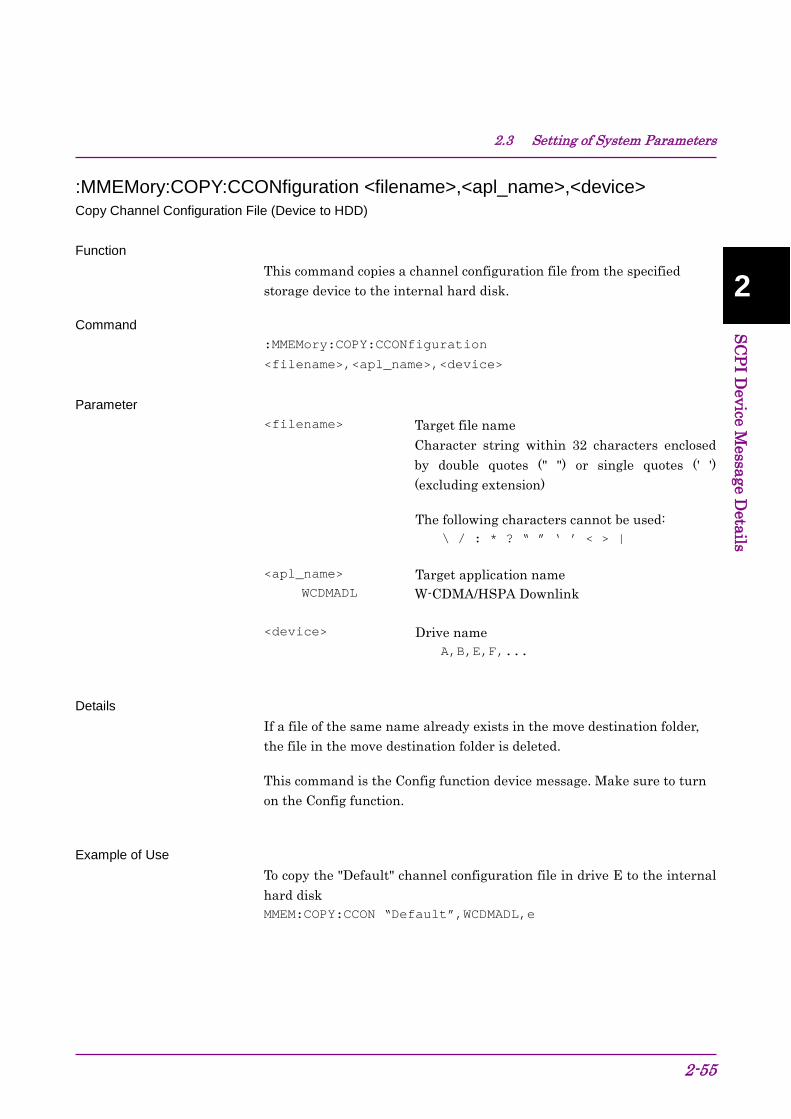
2.3 Setting of System Parameters
2-55
2
SCPI Device M
essage Details
:MMEMory:COPY:CCONfiguration <filename>,<apl_name>,<device> Copy Channel Configuration File (Device to HDD)
Function
This command copies a channel configuration file from the specified storage device to the internal hard disk.
Command :MMEMory:COPY:CCONfiguration
<filename>,<apl_name>,<device>
Parameter <filename> Target file name
Character string within 32 characters enclosed by double quotes (" ") or single quotes (' ') (excluding extension)
The following characters cannot be used: \ / : * ? “ ” ‘ ’ < > |
<apl_name> Target application name WCDMADL W-CDMA/HSPA Downlink
<device> Drive name A,B,E,F,...
Details
If a file of the same name already exists in the move destination folder, the file in the move destination folder is deleted.
This command is the Config function device message. Make sure to turn on the Config function.
Example of Use
To copy the "Default" channel configuration file in drive E to the internal hard disk MMEM:COPY:CCON “Default”,WCDMADL,e

Chapter 2 SCPI Device Message Details
2-56
:MMEMory:DELete:CCONfiguration <filename>,<apl_name>,<device> Delete Channel Configuration File Function
This command deletes a channel configuration file from the specified storage device.
Command :MMEMory:DELete:CCONfiguration
<filename>,<apl_name>,<device>
Parameter <filename> Target file name
Character string within 32 characters enclosed by double quotes (" ") or single quotes (' ') (excluding extension)
The following characters cannot be used: \ / : * ? “ ” ‘ ’ < > |
<apl_name> Target application name WCDMADL W-CDMA/HSPA Downlink
<device> Drive name A,B,E,F,...
Details
This command is the Config function device message. Make sure to turn on the Config function.
Example of Use
To delete the channel configuration file “Default” saved in drive E
MMEM:DEL:CCON “Default”,WCDMADL,e

2.3 Setting of System Parameters
2-57
2
SCPI Device M
essage Details
:MMEMory:PROTection:CCONfiguration[:STATe] <filename>,ON|OFF|0|1,<apl_name>,<device> Protect Channel Configuration File Function
This command protects a channel configuration file saved in the specified drive. Protected files cannot be deleted.
Command :MMEMory:PROTection:CCONfiguration[:STATe]
<filename>,<switch>,<apl_name>,<device>
Parameter <filename> Target file name
Character string within 32 characters enclosed by double quotes (" ") or single quotes (' ') (excluding extension)
The following characters cannot be used: \ / : * ? “ ” ‘ ’ < > |
<switch> Protection ON/OFF ON|1 Protects the file. OFF|0 Does not protect the file.
<apl_name> Target application name WCDMADL W-CDMA/HSPA Downlink
<device> Drive name A,B,D,E,F,...
Details
This command is the Config function device message. Make sure to turn on the Config function.
Example of Use To protect the channel configuration file “Default” saved in drive E
MMEM:PROT:CCON “Default”,ON,WCDMADL,e

Chapter 2 SCPI Device Message Details
2-58
:MMEMory:PROTection:CCONfiguration[:STATe]? <filename>,<apl_name>,<device> Protect Channel Configuration File Query Function
This command queries the protection status of a channel configuration file saved in the specified drive.
Query :MMEMory:PROTection: CCONfiguration[:STATe]? <filename>,<apl_name>,<device>
Response <switch>
Parameter <filename> Target file name
Character string within 32 characters enclosed by double quotes (" ") or single quotes (' ') (excluding extension)
The following characters cannot be used: \ / : * ? “ ” ‘ ’ < > |
<apl_name> Target application name WCDMADL W-CDMA/HSPA Downlink
<device> Drive name A,B,D,E,F,...
<switch> Protection ON/OFF 1 Protects the file. 0 Does not protect the file.
Details
This command is the Config function device message. Make sure to turn on the Config function.
Example of Use To query the protection status of the channel configuration file “Default” saved in drive E
MMEM:PROT:CCON? “Default”,WCDMADL,e
> 1

2.3 Setting of System Parameters
2-59
2
SCPI Device M
essage Details
MMEMory:CATalog:CCONfiguration? <apl_name>,<device> Channel Configuration File List Query Function
This command queries a list of channel configuration files saved in the specified device.
Query MMEMory:CATalog:CCONfiguration? <apl_name>,<device>
Response <number>,<filename_1>,<filename_2>・・・
Parameter
<device> Drive name A,B,D,E,F,...
<apl_name> Target application name WCDMADL W-CDMA/HSPA Downlink
<number> Number of files Range 0 to 1000
<filename> File name When files more than 1000 exist, the command sorts them by file name and returns the top 1000 files.
Details This command is the Config function device message. Make sure to turn on the Config function.
Example of Use To query the list of channel configuration files saved in drive E
MMEM:CAT:CCON? WCDMADL,e
>3,Param_00,Param_01,Param_02
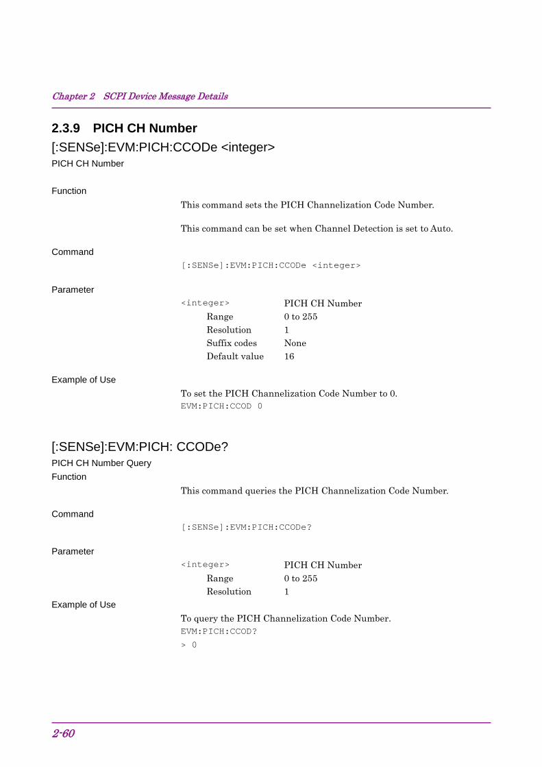
Chapter 2 SCPI Device Message Details
2-60
2.3.9 PICH CH Number [:SENSe]:EVM:PICH:CCODe <integer> PICH CH Number Function
This command sets the PICH Channelization Code Number.
This command can be set when Channel Detection is set to Auto.
Command [:SENSe]:EVM:PICH:CCODe <integer>
Parameter <integer> PICH CH Number
Range 0 to 255 Resolution 1 Suffix codes None Default value 16
Example of Use To set the PICH Channelization Code Number to 0. EVM:PICH:CCOD 0
[:SENSe]:EVM:PICH: CCODe? PICH CH Number Query Function
This command queries the PICH Channelization Code Number.
Command [:SENSe]:EVM:PICH:CCODe?
Parameter <integer> PICH CH Number
Range 0 to 255 Resolution 1
Example of Use To query the PICH Channelization Code Number. EVM:PICH:CCOD?
> 0
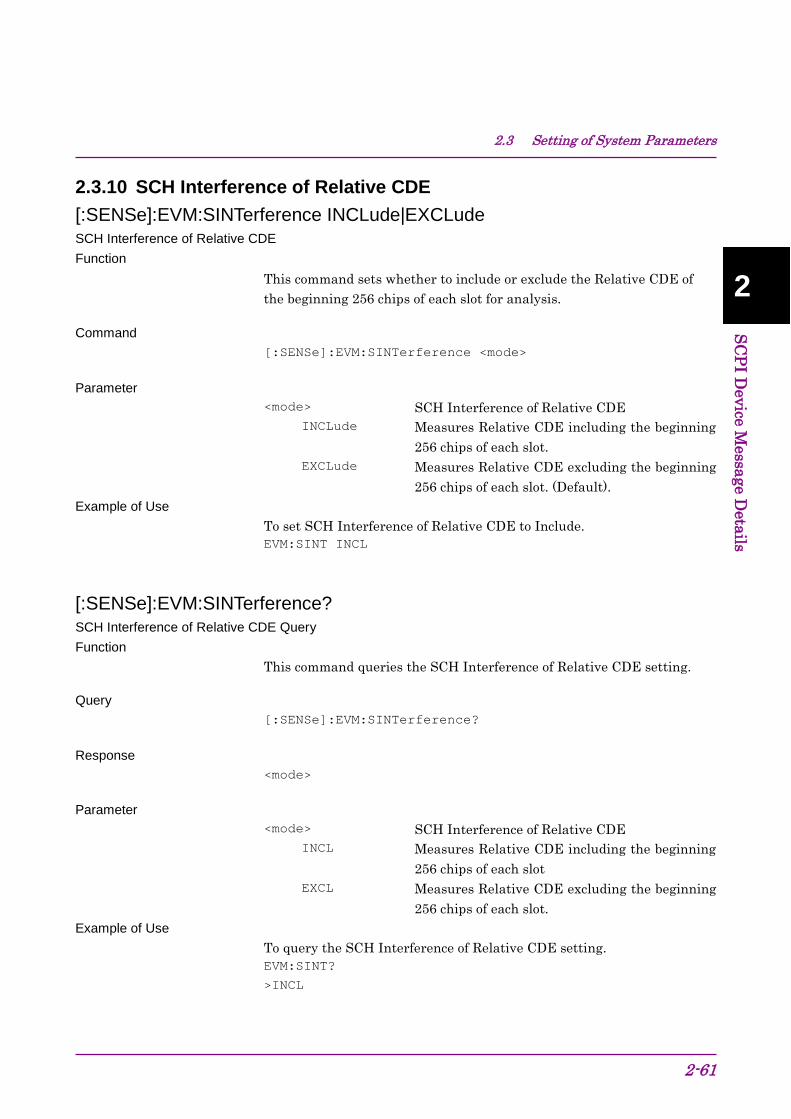
2.3 Setting of System Parameters
2-61
2
SCPI Device M
essage Details
2.3.10 SCH Interference of Relative CDE [:SENSe]:EVM:SINTerference INCLude|EXCLude SCH Interference of Relative CDE Function
This command sets whether to include or exclude the Relative CDE of the beginning 256 chips of each slot for analysis.
Command [:SENSe]:EVM:SINTerference <mode>
Parameter <mode> SCH Interference of Relative CDE
INCLude Measures Relative CDE including the beginning 256 chips of each slot.
EXCLude Measures Relative CDE excluding the beginning 256 chips of each slot. (Default).
Example of Use To set SCH Interference of Relative CDE to Include. EVM:SINT INCL
[:SENSe]:EVM:SINTerference? SCH Interference of Relative CDE Query Function
This command queries the SCH Interference of Relative CDE setting.
Query [:SENSe]:EVM:SINTerference?
Response <mode>
Parameter <mode> SCH Interference of Relative CDE
INCL Measures Relative CDE including the beginning 256 chips of each slot
EXCL Measures Relative CDE excluding the beginning 256 chips of each slot.
Example of Use To query the SCH Interference of Relative CDE setting. EVM:SINT?
>INCL

Chapter 2 SCPI Device Message Details
2-62
2.3.11 Peak Relative CDE Detection Mode [:SENSe]:EVM:PRDM SLOT|MINT Peak Relative CDE Detection Mode Function
This command sets a segment for Calculating Peak Relative CDE
Command [:SENSe]:EVM:PRDM SLOT|MINT
Parameter <mode> Peak Relative CDE Detection Mode
SLOT slot (Default) MINT Measurement Interval
Example of Use To set Peak Relative CDE Detection Mode to Measurement Interval. EVM:PRDM MINT
[:SENSe]:EVM:PRDM? Peak Relative CDE Detection Mode Query Function
This command queries a segment for Calculating Peak Relative CDE.
Query [:SENSe]:EVM:PRDM?
Response <mode>
Parameter <mode> Peak Relative CDE Detection Mode
SLOT slot MINT Measurement Interval
Example of Use To query the settings of Peak Relative CDE Detection Mode. EVM:PRDM?
> MINT

2.4 Utility Functions
2-63
2
SCPI Device M
essage Details
2.4 Utility Functions Table 2.4-1 lists device messages for utility functions to be measured.
Table 2.4-1 Utility Functions
Function Device Message Erase Warm Up Message :DISPlay:ANNotation:WUP:ERASe
Display Title :DISPlay:ANNotation:TITLe[:STATe] ON|OFF|1|0
:DISPlay:ANNotation:TITLe[:STATe]?
Title Entry :DISPlay:ANNotation:TITLe:DATA <string>
:DISPlay:ANNotation:TITLe:DATA?

Chapter 2 SCPI Device Message Details
2-64
2.4.1 Erase Warm Up Message :DISPlay:ANNotation:WUP:ERASe Erase Warm Up Message Function
This command hides the warm-up messages that are displayed right after activation.
Command :DISPlay:ANNotation:WUP:ERASe
Example of Use To delete the warm-up message. DISP:ANN:WUP:ERAS

2.4 Utility Functions
2-65
2
SCPI Device M
essage Details
2.4.2 Display Title :DISPlay:ANNotation:TITLe[:STATe] OFF|ON|0|1 Display Title Function
This command sets the title display On/Off.
Command :DISPlay:ANNotation:TITLe[:STATe] <switch>
Parameter <switch> Title display On/Off
OFF|0 Off ON|1 On (Default value)
Example of Use To display the title. DISP:ANN:TITL ON
:DISPlay:ANNotation:TITLe[:STATe]? Display Title Query Function
This command queries the title display On/Off.
Query :DISPlay:ANNotation:TITLe[:STATe]?
Response <switch>
Parameter <switch> Title display On/Off
0 Off 1 On
Example of Use To query the title display On/Off. DISP:ANN:TITL?
> 1

Chapter 2 SCPI Device Message Details
2-66
2.4.3 Title Entry :DISPlay:ANNotation:TITLe:DATA <string> Title Entry Function
This command sets the title character string.
Command :DISPlay:ANNotation:TITLe:DATA <string>
Parameter <string> Character string within 32 characters enclosed
by double quotes (“ ”) or single quotes (‘ ’)
Example of Use To set the title character string. DISP:ANN:TITL:DATA ‘TEST’
:DISPlay:ANNotation:TITLe:DATA? Title Entry Query Function
This command queries the title character string.
Query :DISPlay:ANNotation:TITLe:DATA?
Response <string>
Parameter <string> Character string within 32 characters enclosed
by double quotes (“ ”) or single quotes (‘ ’)
Example of Use To query the title character string. DISP:ANN:TITL:DATA?
> TEST

2.5 Common Measurement Function
2-67
2
SCPI Device M
essage Details
2.5 Common Measurement Function Table 2.5-1 lists device messages for performing operations common to all the measurement functions.
Table 2.5-1 Common Measurement Function
Function Device Message
Continuous Measurement
:INITiate:CONTinuous OFF|ON|0|1
:INITiate:CONTinuous?
:INITiate:MODE:CONTinuous
Single Measurement :INITiate:MODE:SINGle
Initiate :INITiate[:IMMediate]
Configure :CONFigure?
Trigger Switch :TRIGger[:SEQuence][:STATe] OFF|ON|0|1
:TRIGger[:SEQuence][:STATe]?
Trigger Source
:TRIGger[:SEQuence]:SOURce EXTernal[1|2]|EXT2|IMMediate|SG
:TRIGger[:SEQuence]:SOURce?
:TRIGger:RHO[:SEQuence]:SOURce EXTernal[1|2]|EXT2|IMMediate|SG
:TRIGger:RHO[:SEQuence]:SOURce?
:TRIGger:CDPower[:SEQuence]:SOURce EXTernal[1|2]|EXT2|IMMediate|SG
:TRIGger:CDPower[:SEQuence]:SOURce?
Trigger Slope
:TRIGger[:SEQuence]:SLOPe POSitive|NEGative
:TRIGger[:SEQuence]:SLOPe?
:TRIGger[:SEQuence]:EXTernal[1|2]:SLOPe POSitive|NEGative
:TRIGger[:SEQuence]:EXTernal[1|2]:SLOPe?
Trigger Delay
:TRIGger[:SEQuence]:DELay <time>
:TRIGger[:SEQuence]:DELay?
:TRIGger[:SEQuence]:EXTernal[1|2]:DELay <time>
:TRIGger[:SEQuence]:EXTernal[1|2]:DELay?

Chapter 2 SCPI Device Message Details
2-68
2.5.1 Measurement and Control :INITiate:CONTinuous OFF|ON|0|1 Continuous Measurement Function
This command sets continuous or single measurement mode.
Command :INITiate:CONTinuous <switch>
Parameter <switch> Measure mode
0|OFF Single measurement mode 1|ON Continuous measurement mode (Default value)
Details
Continuous measurement starts when On is set, while Single measurement mode is set and no measurement starts when Off is set.
Example of Use To execute continuous measurement. INIT:CONT ON
:INITiate:CONTinuous? Continuous Measurement Query Function
This command queries the measurement mode.
Query :INITiate:CONTinuous?
Response <switch>
Parameter <switch> Capture mode
0 Single measurement mode 1 Continuous measurement mode
Example of Use
To query the measurement mode. INIT:CONT?
> 0

2.5 Common Measurement Function
2-69
2
SCPI Device M
essage Details
:INITiate:MODE:CONTinuous Continuous Measurement Function
This command starts continuous measurement.
Command :INITiate:MODE:CONTinuous
Example of Use To start continuous measurement. INIT:MODE:CONT
:INITiate:MODE:SINGle Single Measurement Function
This command starts single measurement.
Command :INITiate:MODE:SINGle
Example of Use To start single measurement. INIT:MODE:SING
:INITiate[:IMMediate] Initiate Function
This command starts measurement in the current measurement mode.
Command :INITiate:[IMMediate]
Example of Use To start measurement. INIT

Chapter 2 SCPI Device Message Details
2-70
:CONFigure? Configure Query Function
This command queries the current measurement function.
Query :CONFigure?
Response <mode>
Parameter <mode> Measurement function
EVM Modulation Measurement CDP Code Domain Measurement CVT Code vs Time Measurement ACP ACP Measurement CHP Channel Power Measurement OBW OBW Measurement SEM SEM Measurement
Example of Use To query the measurement function. CONF?
> EVM

2.5 Common Measurement Function
2-71
2
SCPI Device M
essage Details
2.5.2 Trigger Switch :TRIGger[:SEQuence][:STATe] OFF|ON|0|1 Trigger Switch Function
This command enables/disables the trigger wait.
Command :TRIGger[:SEQuence][:STATe] <switch>
Parameter <switch> Trigger wait On/Off
OFF|0 Off (Default value) ON|1 On
Example of Use
To enable the trigger wait. TRIG ON
:TRIGger[:SEQuence][:STATe]? Trigger Switch Query Function
This command queries On/Off of the trigger wait.
Query :TRIGger[:SEQuence][:STATe]?
Response <switch>
Parameter <switch> Trigger wait On/Off
0 Off 1 On
Example of Use
To query the trigger wait setting. TRIG?
> 0

Chapter 2 SCPI Device Message Details
2-72
2.5.3 Trigger Source :TRIGger[:SEQuence]:SOURce EXTernal[1|2]|EXT2|IMMediate|SG Trigger Source Function
This command selects the trigger signal source.
Command :TRIGger[:SEQuence]:SOURce <source>
Parameter <source> Trigger signal source
EXTernal[1] External input (External) EXTernal2|EXT2 External input 2 (External 2) IMMediate Free run SG SG Marker
Details
SG Marker can be selected only when Vector Signal Generator option is installed.
External input 2 (External 2) is selectable only for MS2850A.
Example of Use To set the trigger signal source to external input. TRIG:SOUR EXT
Related Command This command has the same function as the following commands. :TRIGger:RHO[:SEQuence]:SOURce
EXTernal[1|2]|EXT2|IMMediate|SG
:TRIGger:CDPower[:SEQuence]:SOURce
EXTernal[1|2]|EXT2|IMMediate|SG
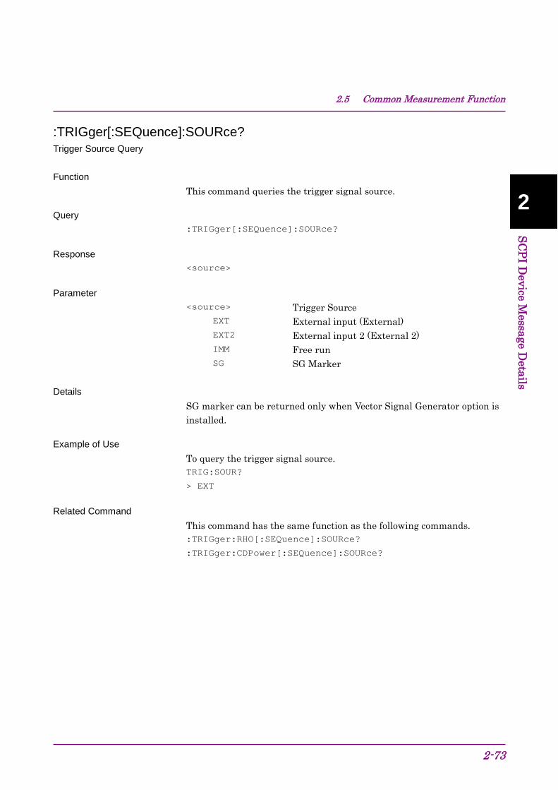
2.5 Common Measurement Function
2-73
2
SCPI Device M
essage Details
:TRIGger[:SEQuence]:SOURce? Trigger Source Query Function
This command queries the trigger signal source.
Query :TRIGger[:SEQuence]:SOURce?
Response <source>
Parameter <source> Trigger Source
EXT External input (External) EXT2 External input 2 (External 2) IMM Free run SG SG Marker
Details
SG marker can be returned only when Vector Signal Generator option is installed.
Example of Use To query the trigger signal source. TRIG:SOUR?
> EXT
Related Command This command has the same function as the following commands. :TRIGger:RHO[:SEQuence]:SOURce?
:TRIGger:CDPower[:SEQuence]:SOURce?

Chapter 2 SCPI Device Message Details
2-74
:TRIGger:RHO[:SEQuence]:SOURce EXTernal[1|2]|EXT2|IMMediate|SG Trigger Source Function
This command selects the trigger signal source.
Refer to TRIGger[:SEQuence]:SOURce <source>
Related Command This command has the same function as the following commands. :TRIGger[:SEQuence]:SOURce
EXTernal[1|2]|EXT2|IMMediate|SG
:TRIGger:CDPower[:SEQuence]:SOURce
EXTernal[1|2]|EXT2|IMMediate|SG

2.5 Common Measurement Function
2-75
2
SCPI Device M
essage Details
:TRIGger:RHO[:SEQuence]:SOURce? Trigger Source Query Function
This command queries the trigger signal source.
Refer to TRIGger[:SEQuence]:SOURce?
Related Command This command has the same function as the following commands. :TRIGger[:SEQuence]:SOURce?
:TRIGger:CDPower[:SEQuence]:SOURce?
:TRIGger:CDPower[:SEQuence]:SOURce EXTernal[1|2]|EXT2|IMMediate|SG Trigger Source Function
This command selects the trigger signal source.
Refer to TRIGger[:SEQuence]:SOURce <source>
Related Command This command has the same function as the following commands. :TRIGger[:SEQuence]:SOURce
EXTernal[1|2]|EXT2|IMMediate|SG
:TRIGger:RHO[:SEQuence]:SOURce
EXTernal[1|2]|EXT2|IMMediate|SG
:TRIGger:CDPower[:SEQuence]:SOURce? Trigger Source Query Function
This command queries the trigger signal source.
Refer to TRIGger[:SEQuence]:SOURce?
Related Command This command has the same function as the following commands. :TRIGger[:SEQuence]:SOURce?
:TRIGger:RHO[:SEQuence]:SOURce?

Chapter 2 SCPI Device Message Details
2-76
2.5.4 Trigger Slope :TRIGger[:SEQuence]:SLOPe POSitive|NEGative Trigger Slope Function
This command sets the trigger detection mode (rising/falling).
Command :TRIGger[:SEQuence]:SLOPe <mode>
Parameter <mode> Trigger detection mode
POSitive Trigger is detected at the rising edge (Default value).
NEGative Trigger is detected at the falling edge.
Example of Use To detect a trigger at the rising edge. TRIG:SLOP POS
Related Command This command has the same function as the following command. :TRIGger[:SEQuence]:EXTernal[1|2]:SLOPe POSitive|NEGative

2.5 Common Measurement Function
2-77
2
SCPI Device M
essage Details
:TRIGger[:SEQuence]:SLOPe? Trigger Slope Query Function
This command queries the trigger detection mode (rising/falling).
Query :TRIGger[:SEQuence]:SLOPe?
Response <mode>
Parameter <mode> Trigger detection mode
POS Trigger is detected at the rising edge. NEG Trigger is detected at the falling edge.
Example of Use To query the trigger detection mode. TRIG:SLOP?
> POS
Related Command This command has the same function as the following command. :TRIGger[:SEQuence]:EXTernal[1|2]:SLOPe?

Chapter 2 SCPI Device Message Details
2-78
:TRIGger[:SEQuence]:EXTernal[1|2]:SLOPe POSitive|NEGative Trigger Slope Function
This command sets the trigger detection mode (rising/falling).
Refer to :TRIGger[:SEQuence]:SLOPe
Related Command This command has the same function as the following command. :TRIGger[:SEQuence]:SLOPe POSitive|NEGative
:TRIGger[:SEQuence]:EXTernal[1|2]:SLOPe? Trigger Slope Query Function
This command queries the trigger detection mode (rising/falling).
Refer to :TRIGger[:SEQuence]:SLOPe?
Related Command This command has the same function as the following command. :TRIGger[:SEQuence]:SLOPe?

2.5 Common Measurement Function
2-79
2
SCPI Device M
essage Details
2.5.5 Trigger Delay :TRIGger[:SEQuence]:DELay <time> Trigger Delay Function
This command sets the delay time from the trigger generation point to the frame starting position.
Command :TRIGger[:SEQuence]:DELay <time>
Parameter <time> Delay time from trigger generation point to
frame starting position Range –2 to +2 s Resolution 20 nanoseconds Suffix codes NS,US,MS,S
Seconds are used when omitted. Default value 0 s
Example of Use To set the trigger delay time to 20 ms. TRIG:DEL 20MS
Related Command This command has the same function as the following command. :TRIGger[:SEQuence]:EXTernal[1|2]:DELay

Chapter 2 SCPI Device Message Details
2-80
:TRIGger[:SEQuence]:DELay? Trigger Delay Query Function
This command queries the delay time from the trigger generation point to the frame starting position.
Query :TRIGger[:SEQuence]:DELay?
Response <time>
Parameter <time> Delay time from trigger generation point to
frame starting position Range –2 to +2 s Resolution 20 nanoseconds
Value is returned in s units.
Example of Use To query the trigger delay time. TRIG:DEL?
> 0.02
Related Command This command has the same function as the following command. :TRIGger[:SEQuence]:EXTernal[1|2]:DELay?

2.5 Common Measurement Function
2-81
2
SCPI Device M
essage Details
:TRIGger[:SEQuence]:EXTernal[1|2]:DELay <time> Trigger Delay Function
This command sets the delay time from the trigger generation point to the frame starting position.
Refer to :TRIGger[:SEQuence]:DELay
Related Command This command has the same function as the following command. :TRIGger[:SEQuence]:DELay <time>
:TRIGger[:SEQuence]:EXTernal[1|2]:DELay? Trigger Delay Query Function
This command queries the delay time from the trigger generation point to the frame starting position.
Refer to :TRIGger[:SEQuence]:DELay?
Related Command This command has the same function as the following command. :TRIGger[:SEQuence]:DELay?

Chapter 2 SCPI Device Message Details
2-82
2.6 ACP/Channel Power/OBW/SEM measurement function
Table 2.6-1 lists device messages to fetch the ACP, Channel Power, OBW, and SEM measurement functions. The application to be used (Signal Analyzer or Spectrum Analyzer) must be activated before executing these device messages.
For details on the commands and queries used for control after these measurement functions are fetched, refer to the “MS2690/MS2691/MS2692A and MS2830A/MS2840A/MS2850A Signal Analyzer Operation Manual (Signal Analyzer Function Remote Control)” or “MS2690/MS2691/MS2692A and MS2830A/MS2840A/MS2850A Signal Analyzer Operation Manual (Spectrum Analyzer Function Remote Control)”.
Table 2.6-1 Fetching ACP/Channel Power/OBW/SEM Measurement Functions
Function Device Message
Configure - ACP :CONFigure[:FFT|SWEPt]:ACP
Configure - Channel Power :CONFigure[:FFT|SWEPt]:CHPower
Configure - OBW :CONFigure[:FFT|SWEPt]:OBWidth
Configure - SEM :CONFigure[:SWEPt]:SEMask
Using application for ACP [:SENSe]:ACPower:INSTrument[:SELect] FFT|SWEPt
[:SENSe]:ACPower:INSTrument[:SELect]?
Using application for Channel Power [:SENSe]:CHPower:INSTrument[:SELect] FFT|SWEPt
[:SENSe]:CHPower:INSTrument[:SELect]?
Using application for OBW [:SENSe]:OBWidth:INSTrument[:SELect] FFT|SWEPt
[:SENSe]:OBWidth:INSTrument[:SELect]?
Coupled Ref & ATT in Swept & FFT [:SENSe]:ASETting:CATT OFF|ON|0|1
Note:
With the exception of the Modulation, Code Domain, and Code vs Time measurements, FETCh:<measure>, INITiate:<measure>, READ:<measure>, and MEASure:<measure> cannot be used when this application is selected. These commands and queries can be used when Signal Analyzer or Spectrum Analyzer is selected after CONFigure:<measure> is executed.

2.6 ACP/Channel Power/OBW/SEM measurement function
2-83
2
SCPI Device M
essage Details
:CONFigure[:FFT|SWEPt]:ACP ACP Function
This command selects the ACP measurement function.
When FFT or SWEPt is omitted, the measurement mode to be used can be set by [:SENSe]:ACPower:INSTrument[:SELect] FFT|SWEPt.
Command :CONFigure[:FFT|SWEPt]:ACP
Details No measurement is made.
For MS2830A: To perform FFT measurement using the Signal Analyzer function with this command, the analysis bandwidth option 31.25 MHz or greater is required in all cases.
Example of Use To select the ACP measurement function of Spectrum Analyzer. CONF:SWEP:ACP

Chapter 2 SCPI Device Message Details
2-84
:CONFigure[:FFT|SWEPt]:CHPower Channel Power Function
This command selects the Channel Power measurement function.
When FFT or SWEPt is omitted, the measurement mode to be used can be set by [:SENSe]:CHPower:INSTrument[:SELect] FFT|SWEPt.
Command :CONFigure[:FFT|SWEPt]:CHPower
Details No measurement is made.
For MS2830A: To perform FFT measurement using the Signal Analyzer function with this command, the analysis bandwidth option 31.25 MHz or greater is required in all cases.
Example of Use To select the Channel Power measurement function of Spectrum Analyzer. CONF:SWEP:CHP
2.6 ACP/Channel Power/OBW/SEM measurement function
2-85
2
SCPI Device M
essage Details
:CONFigure[:FFT|SWEPt]:OBWidth OBW Function
This command selects the OBW measurement function.
When FFT or SWEPt is omitted, the measurement mode to be used can be set by [:SENSe]:OBWidth:INSTrument[:SELect] FFT|SWEPt.
Command :CONFigure[:FFT|SWEPt]:OBWidth
Details No measurement is made.
For MS2830A: To perform FFT measurement using the Signal Analyzer function with this command, the analysis bandwidth option 31.25 MHz or greater is required in all cases.
Example of Use To select the OBW measurement function of Spectrum Analyzer. CONF:SWEP:OBW
:CONFigure[:SWEPt]:SEMask SEM Function
This command selects the SEM measurement function.
Command :CONFigure[:SWEPt]:SEMask
Details No measurement is made. The SEM measurement function is available only with Spectrum Analyzer.
Example of Use To select the SEM measurement function of Spectrum Analyzer. CONF:SEM

Chapter 2 SCPI Device Message Details
2-86
[:SENSe]:ACPower:INSTrument[:SELect] FFT|SWEPt Measurement Method for ACP Function
This command sets the measurement mode to be applied when :CONFigure:ACP is executed.
Command [:SENSe]:ACPower:INSTrument[:SELect] <mode>
Parameter <mode> Measurement mode
FFT Signal Analyzer function SWEPt Spectrum Analyzer function (Default value)
Details FFT can be set with MS2830A, however, to execute with CONFigure command, the analysis bandwidth option 31.25 MHz or greater is required.
Example of Use To use the Signal Analyzer function during ACP measurement. ACP:INST SWEP

2.6 ACP/Channel Power/OBW/SEM measurement function
2-87
2
SCPI Device M
essage Details
[:SENSe]:ACPower:INSTrument[:SELect]? Measurement Method for ACP Query Function
This command queries the measurement mode to be applied when :CONFigure:ACP is executed.
Query [:SENSe]:ACPower:INSTrument[:SELect]?
Response <mode>
Parameter <mode> Measurement mode
FFT Signal Analyzer function SWEP Spectrum Analyzer function
Details FFT can be set with MS2830A, however, to execute with CONFigure command, the analysis bandwidth option 31.25 MHz or greater is required.
Example of Use To query the measurement mode used during ACP measurement. ACP:INST?
> FFT

Chapter 2 SCPI Device Message Details
2-88
[:SENSe]:CHPower:INSTrument[:SELect] FFT|SWEPt Measurement Method for Channel Power Function
This command sets the measurement mode to be applied when :CONFigure:CHPower is executed.
Command [:SENSe]:CHPower:INSTrument[:SELect] <mode>
Parameter <mode> Measurement mode
FFT Signal Analyzer function SWEPt Spectrum Analyzer function (Default value)
Details FFT can be set with MS2830A, however, to execute with CONFigure command, the analysis bandwidth option 31.25 MHz or greater is required.
Example of Use To use the Signal Analyzer function during Channel Power measurement. CHP:INST SWEP

2.6 ACP/Channel Power/OBW/SEM measurement function
2-89
2
SCPI Device M
essage Details
[:SENSe]:CHPower:INSTrument[:SELect]? Measurement Method for Channel Power Query Function
This command queries the measurement mode to be applied when :CONFigure:CHPower is executed.
Query [:SENSe]:CHPower:INSTrument[:SELect]?
Response <mode>
Parameter <mode> Measurement mode
FFT Signal Analyzer function SWEP Spectrum Analyzer function
Details FFT can be set with MS2830A, however, to execute with CONFigure command, the analysis bandwidth option 31.25 MHz or greater is required.
Example of Use To query the measurement mode used during Channel Power measurement. CHP:INST?
> FFT
Chapter 2 SCPI Device Message Details
2-90
[:SENSe]:OBWidth:INSTrument[:SELect] FFT|SWEPt Measurement Method for OBW Function
This command sets the measurement mode to be applied when :CONFigure:OBWidth is executed.
Command [:SENSe]:OBWidth:INSTrument[:SELect] <mode>
Parameter <mode> Measurement mode
FFT Signal Analyzer function SWEPt Spectrum Analyzer function (Default value)
Details FFT can be set with MS2830A, however, to execute with CONFigure command, the analysis bandwidth option 31.25 MHz or greater is required.
Example of Use To use the Signal Analyzer function during OBW measurement. OBW:INST SWEP

2.6 ACP/Channel Power/OBW/SEM measurement function
2-91
2
SCPI Device M
essage Details
[:SENSe]:OBWidth:INSTrument[:SELect]? Measurement Method for OBW Query Function
This command queries the measurement mode to be applied when :CONFigure: OBWidth is executed.
Query [:SENSe]:OBWidth:INSTrument[:SELect]?
Response <mode>
Parameter <mode> Measurement mode
FFT Signal Analyzer function SWEP Spectrum Analyzer function
Details FFT can be set with MS2830A, however, to execute with CONFigure command, the analysis bandwidth option 31.25 MHz or greater is required.
Example of Use To query the measurement mode used during OBW measurement. OBW:INST?
> FFT

Chapter 2 SCPI Device Message Details
2-92
[:SENSe]:ASETting:CATT OFF|ON|0|1 Coupled Ref & ATT in Swept & FFT Function
This command sets whether to inherit ATT setting when switching function among the followings:
ACP (Swept), ACP (FFT), Channel Power (Swept), Channel Power (FFT), OBW (FFT), OBW (Swept), Spectrum Emission Mask (Swept)
Command [:SENSe]:ASETting:CATT <switch>
Parameter <switch>
0|OFF Does not inherit the setting (Default) 1|ON Inherits the setting
Details If switching function via other Measure functions or other applications, the ATT setting will not be inherited.
Example of Use To inherit the ATT setting when switching among Measure function (Swept/FFT). ASET:CATT ON
2.6 ACP/Channel Power/OBW/SEM measurement function
2-93
2
SCPI Device M
essage Details
[:SENSe]:ASETting:CATT? Coupled Ref & ATT in Swept & FFT Query Function
This command queries the setting of whether to inherit ATT setting when switching function among the followings:
ACP (Swept), ACP (FFT), Channel Power (Swept), Channel Power (FFT), OBW (FFT), OBW (Swept), Spectrum Emission Mask (Swept)
Query [:SENSe]:ASETting:CATT?
Response <switch>
Parameter <switch>
0 Does not inherit the setting 1 Inherits the setting
Details If switching function via other Measure functions or other applications, the ATT setting will not be inherited.
Example of Use To query the setting of whether to inherit the ATT setting when switching among Measure function (Swept/FFT). ASET:CATT?
>1
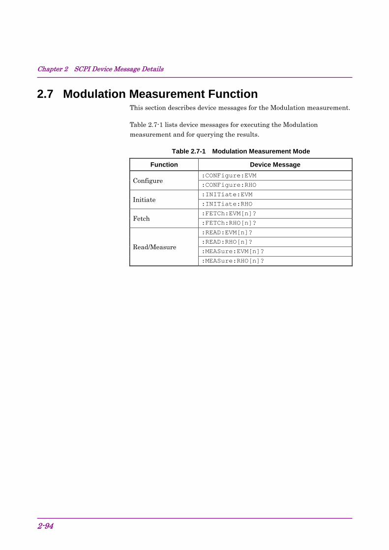
Chapter 2 SCPI Device Message Details
2-94
2.7 Modulation Measurement Function This section describes device messages for the Modulation measurement.
Table 2.7-1 lists device messages for executing the Modulation measurement and for querying the results.
Table 2.7-1 Modulation Measurement Mode
Function Device Message
Configure :CONFigure:EVM
:CONFigure:RHO
Initiate :INITiate:EVM
:INITiate:RHO
Fetch :FETCh:EVM[n]?
:FETCh:RHO[n]?
Read/Measure
:READ:EVM[n]?
:READ:RHO[n]?
:MEASure:EVM[n]?
:MEASure:RHO[n]?

2.7 Modulation Measurement Function
2-95
2
SCPI Device M
essage Details
Table 2.7-2 lists the responses to parameter n in Table 2.7-1.
Table 2.7-2 Responses to Modulation Measurement Results
n Result Mode Response
1 or omitted
A
Returns the measurement results with comma separated value in the following order: 1. RMS EVM [%] (Average value for Storage Count) 2. Peak EVM [%] (Maximum value for Storage Count) 3. Magnitude Error [%] (Average value for Storage Count) 4. Phase Error [degree] (Average value for Storage Count) 5. I/Q Origin Offset [dB] (Average value for Storage Count) 6. Frequency Error [Hz] (Average value for Storage Count) 7. Frequency Error [ppm] (Average value for Storage Count) 8. Peak CDE [dB] (Maximum value for Storage Count) 9. Code number at Peak CDE 10. –999.0 11. Time Offset [chips] (Average value for Storage Count)
Note: When trigger Switch is Off: –999.0 12. P−CPICH Power[dB] (Average value for Storage Count) 13. Mean Power [dBm] (Average value for Storage Count) 14. Peak Active CDE [dB] (Maximum value for Storage Count) 15. Code number at Peak Active CDE 16. Spreading Factor at Peak Active CDE (Maximum value for
Storage Count) 17. –999.0 18. Peak Relative CDE[dB] (Maximum value for Storage Count) 19. Code number at Peak Relative CDE
B
Returns the measurement results with comma separated value in the following order: 1. EVM (RMS) [%] (Average value for Storage Count) 2. EVM (Peak) [%] (Maximum value for Storage Count) 3. Magnitude Error [%] (Average value for Storage Count) 4. Phase Error [degree] (Average value for Storage Count) 5. I/Q Origin Offset [dB] (Average value for Storage Count) 6. Frequency Error [Hz] (Average value for Storage Count) 7. –999.0 8. Peak CDE [dB] (Maximum value for Storage Count) 9. Code number at Peak CDE 10. –999.0 11. Time Offset [chips] (Average value for Storage Count)
Note: When trigger Switch is Off: –999.0 12. P−CPICH Power[dB] (Average value for Storage Count) 13. Mean Power [dBm] (Average value for Storage Count)

Chapter 2 SCPI Device Message Details
2-96
Table 2.7-2 Responses to Modulation Measurement Results (Cont’d)
n Result Mode Response
2 A/B Returns the EVM graph display data from the 0th to the 2559th chips in comma-separated value format. Unit: %
3 A/B Returns the Magnitude Error graph display data from the 0th to the 2559th chips in comma-separated value format. Unit: %
4 A/B Returns the Phase Error graph display data from the 0th to the 2559th chips in comma-separated value format. Unit: degree
5 A/B Returns the Constellation display data from the 0th to the 2559th chips in comma-separated value formats, alternating IQs. No unit
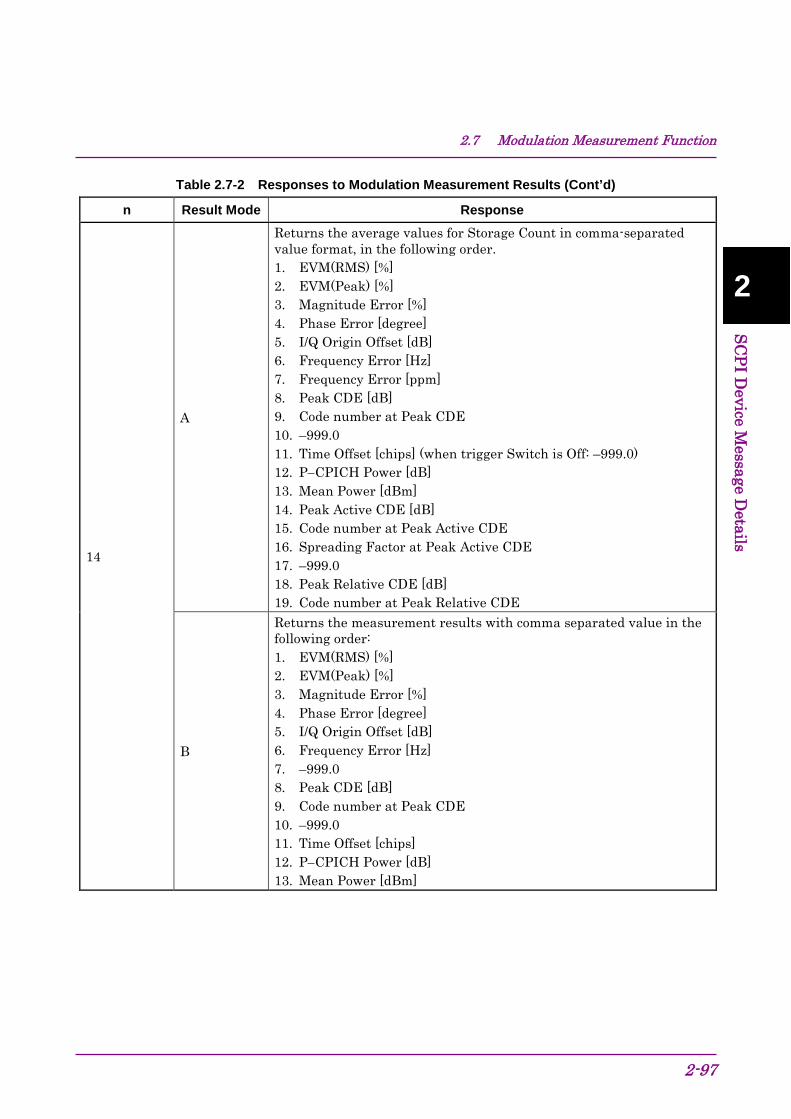
2.7 Modulation Measurement Function
2-97
2
SCPI Device M
essage Details
Table 2.7-2 Responses to Modulation Measurement Results (Cont’d)
n Result Mode Response
14
A
Returns the average values for Storage Count in comma-separated value format, in the following order. 1. EVM(RMS) [%] 2. EVM(Peak) [%] 3. Magnitude Error [%] 4. Phase Error [degree] 5. I/Q Origin Offset [dB] 6. Frequency Error [Hz] 7. Frequency Error [ppm] 8. Peak CDE [dB] 9. Code number at Peak CDE 10. –999.0 11. Time Offset [chips] (when trigger Switch is Off: –999.0) 12. P−CPICH Power [dB] 13. Mean Power [dBm] 14. Peak Active CDE [dB] 15. Code number at Peak Active CDE 16. Spreading Factor at Peak Active CDE 17. –999.0 18. Peak Relative CDE [dB] 19. Code number at Peak Relative CDE
B
Returns the measurement results with comma separated value in the following order: 1. EVM(RMS) [%] 2. EVM(Peak) [%] 3. Magnitude Error [%] 4. Phase Error [degree] 5. I/Q Origin Offset [dB] 6. Frequency Error [Hz] 7. –999.0 8. Peak CDE [dB] 9. Code number at Peak CDE 10. –999.0 11. Time Offset [chips] 12. P−CPICH Power [dB] 13. Mean Power [dBm]

Chapter 2 SCPI Device Message Details
2-98
Table 2.7-2 Responses to Modulation Measurement Results (Cont’d)
n Result Mode Response
15
A
Returns the maximum values for Storage Count in comma-separated value format, in the following order. 1. EVM(RMS) [%] 2. EVM(Peak) [%] 3. Magnitude Error [%] 4. Phase Error [degree] 5. I/Q Origin Offset [dB] 6. Frequency Error [Hz] 7. Frequency Error [ppm] 8. Peak CDE [dB] 9. Code number at Peak CDE 10. –999.0 11. Time Offset [chips] (when trigger Switch is Off: –999.0) 12. P−CPICH Power [dB] 13. Mean Power [dBm] 14. Peak Active CDE [dB] 15. Code number at Peak Active CDE 16. Spreading Factor at Peak Active CDE 17. –999.0 18. Peak Relative CDE [dB] 19. Code number at Peak Relative CDE
B
Returns the measurement results with comma separated value in the following order: 1. EVM(RMS) [%] 2. EVM(Peak) [%] 3. Magnitude Error [%] 4. Phase Error [degree] 5. I/Q Origin Offset [dB] 6. Frequency Error [Hz] 7. –999.0 8. Peak CDE [dB] 9. Code number at Peak CDE 10. –999.0 11. Time Offset [chips] 12. P−CPICH Power [dB] 13. Mean Power [dBm]

2.7 Modulation Measurement Function
2-99
2
SCPI Device M
essage Details
Table 2.7-2 Responses to Modulation Measurement Results (Cont’d)
n Result Mode Response
16 A
Returns the Relative CDE measurement results on the Summary screen. The measurement results when Storage Mode is set to Off or the average values for Storage Count are returned for channels whose SF is 16, in order from CH0 to CH15. For channels whose modulation mode has never been detected as 64QAM, −999.0 is returned.
B –999.0
17 A
Returns the Relative CDE measurement results on the Summary screen. The maximum values for Storage Count are returned for channels whose SF is 16, in order from CH0 to CH15. For channels whose modulation mode has never been detected as 64QAM, −999.0 is returned.
B –999.0

Chapter 2 SCPI Device Message Details
2-100
Table 2.7-2 Responses to Modulation Measurement Results (Cont’d)
n Result Mode Response
18 A
Returns the modulation analysis measurement results on the Summary screen. Responses are returned with comma-separated value formats in the following order: 1. RMS EVM [%](Average value for Storage Count) 2. Peak EVM [%] (Maximum value for Storage Count) 3. Magnitude Error [%] (Average value for Storage Count) 4. Phase Error [degree] (Average value for Storage Count) 5. I/Q Origin Offset [dB] (Average value for Storage Count) 6. Frequency Error [Hz] (Average value for Storage Count) 7. Frequency Error [ppm] (Average value for Storage Count) 8. Peak CDE [dB] (Maximum value for Storage Count) 9. Code number at Peak CDE 10. –999.0 11. Time Offset [chips] (Average value for Storage Count)
Note: When Trigger Switch is Off: –999.0 12. P−CPICH Power[dB] (Average value for Storage Count) 13. Mean Power [dBm] (Average value for Storage Count) 14. Peak Active CDE [dB] (Maximum value for Storage Count) 15. Code number at Peak Active CDE 16. Spreading Factor at Peak Active CDE (Maximum value for
Storage Count) 17. Average Relative CDE [dB] (Average value for Storage Count)* 18. Peak Relative CDE[dB] (Maximum value for Storage Count) 19. Code number at Peak Relative CDE 20. –999.0 21. I/Q Imbalance[%] (Average value for Storage Count) 22.to 50. –999.0
B –999.0 *: Average Relative CDE is not displayed on the Summary screen.
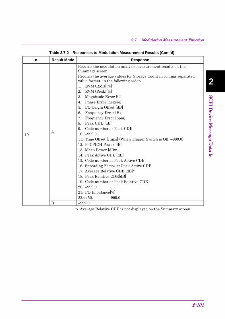
2.7 Modulation Measurement Function
2-101
2
SCPI Device M
essage Details
Table 2.7-2 Responses to Modulation Measurement Results (Cont’d)
n Result Mode Response
19 A
Returns the modulation analysis measurement results on the Summary screen. Returns the average values for Storage Count in comma-separated value format, in the following order: 1. EVM (RMS)[%] 2. EVM (Peak)[%] 3. Magnitude Error [%] 4. Phase Error [degree] 5. I/Q Origin Offset [dB] 6. Frequency Error [Hz] 7. Frequency Error [ppm] 8. Peak CDE [dB] 9. Code number at Peak CDE 10. –999.0 11. Time Offset [chips] (When Trigger Switch is Off: –999.0) 12. P−CPICH Power[dB] 13. Mean Power [dBm] 14. Peak Active CDE [dB] 15. Code number at Peak Active CDE 16. Spreading Factor at Peak Active CDE 17. Average Relative CDE [dB]* 18. Peak Relative CDE[dB] 19. Code number at Peak Relative CDE 20. –999.0 21. I/Q Imbalance[%] 22.to 50. –999.0
B –999.0 *: Average Relative CDE is not displayed on the Summary screen.

Chapter 2 SCPI Device Message Details
2-102
Table 2.7-2 Responses to Modulation Measurement Results (Cont’d)
n Result Mode Response
20 A
Returns the modulation analysis measurement results on the Summary screen. Returns the maximum values for Storage Count in comma-separated value format, in the following order: 1. EVM (RMS)[%] 2. EVM (Peak)[%] 3. Magnitude Error [%] 4. Phase Error [degree] 5. I/Q Origin Offset [dB] 6. Frequency Error [Hz] 7. Frequency Error [ppm] 8. Peak CDE [dB] 9. Code number at Peak CDE 10. –999.0 11. Time Offset [chips] (When Trigger Switch is Off: –999.0) 12. P−CPICH Power[dB] 13. Mean Power [dBm] 14. Peak Active CDE [dB] 15. Code number at Peak Active CDE 16. Spreading Factor at Peak Active CDE 17. Average Relative CDE[dB] * 18. Peak Relative CDE[dB] 19. Code number at Peak Relative CDE 20. –999.0 21. I/Q Imbalance[%] 22. to 50. –999.0
B –999.0
*: Average Relative CDE is not displayed on the Summary screen.

2.7 Modulation Measurement Function
2-103
2
SCPI Device M
essage Details
Table 2.7-2 Responses to Modulation Measurement Results (Cont’d)
n Result Mode Response
21 A
Returns the EVM (RMS) measurement results for each slot. Returns the measurement results when Storage Mode is Off or the average value for Count per slot in order from slot0 to slot14. Returns –999.0 for the result of the slot other than the measurement target.
B –999.0
22 A
Returns the EVM (RMS) measurement results for each slot. Returns the maximum value for Storage Count per slot, in order from slot0 to slot14. Returns –999.0 for the result of the slot other than the measurement target.
B –999.0
23 A
Returns the Frequency Error (%) measurement results for each slot. Returns the measurement results when Storage Mode is Off or the average value for Storage Count per slot in order from slot0 to slot14. Returns –999.0 for the result of the slot other than the measurement target.
B –999.0
24 A
Returns the Frequency Error (%) measurement results for each slot. Returns the maximum value for Storage Count per slot, in order from slot0 to slot14. Returns –999.0 for the result of the slot other than the measurement target.
B –999.0
25 A
Returns the Frequency Error (ppm)measurement results for each slot. Returns the measurement results when Storage Mode is Off or the average value for Storage Count per slot in order from slot0 to slot14. Returns –999.0 for the result of the slot other than the measurement target.
B –999.0
26 A
Returns the Frequency Error (ppm)measurement results for each slot. Returns the maximum value for Storage Count per slot, in order from slot0 to slot14. Returns –999.0 for the result of the slot other than the measurement target.
B –999.0

Chapter 2 SCPI Device Message Details
2-104
Table 2.7-2 Responses to Modulation Measurement Results (Cont’d)
n Result Mode Response
27 A
Returns the PeakCDE measurement results for each slot. Returns the measurement results when Storage Mode is Off or the average value for Storage Count per slot in order from slot0 to slot14. Returns –999.0 for the result of the slot other than the measurement target.
B –999.0
28 A
Returns the PeakCDE measurement results for each slot. Returns the maximum value for Storage Count per slot, in order from slot0 to slot14. Returns –999.0 for the result of the slot other than the measurement target.
B –999.0
29 A
Returns the Average Relative CDE measurement results for each slot. Average Relative CDE is the average value calculated by all active code Relative CDE as SF16 and 64QAM in the target slot. Returns the measurement results when Storage Mode is Off or the average value for Storage Count per slot in order from slot0 to slot14. Returns –999.0 for the result of the slot other than the measurement target.
B –999.0
30 A
Returns the Average Relative CDE measurement results for each slot. Average Relative CDE is the average value calculated by all active code Relative CDE as SF16 and 64QAM in the target slot. Returns the maximum value for Storage Count per slot, in order from slot0 to slot14. Returns –999.0 for the result of the slot other than the measurement target.
B –999.0
31 A
Returns the Average Relative CDE measurement results Average Relative CDE is the average value calculated by all active code Relative CDE as SF16 and 64QAM in all slot set at Measurement Interval. Returns the measurement result when Storage Mode is Off or the average value for Storage Count.
B –999.0
32 A
Returns the Average Relative CDE measurement results. Average Relative CDE is the average value calculated by all active code Relative CDE as SF16 and 64QAM in all slot set at Measurement Interval. Returns the maximum value for Storage Count.
B –999.0

2.7 Modulation Measurement Function
2-105
2
SCPI Device M
essage Details
Table 2.7-3 lists the device messages for setting parameters of Modulation measurement.
Table 2.7-3 Setting Parameters of Modulation Measurement
Parameter Device Message
Starting Slot Number
:CALCulate:EVM:SWEep:STARt: <integer>
:CALCulate:EVM:SWEep:STARt?
:CALCulate:RHO:SWEep:OFFSet <integer>
:CALCulate:RHO:SWEep:OFFSet?
Measurement Interval :CALCulate:EVM:SWEep:INTerval <integer>
:CALCulate:EVM:SWEep:INTerval?
Trace Mode :DISPlay:EVM[:VIEW][:SELect] EVM|MAGNitude|PHASe
:DISPlay:EVM[:VIEW][:SELect]?
Target Slot Number :DISPlay:EVM[:VIEW]:SLOT <integer>
:DISPlay:EVM[:VIEW]:SLOT?
Scale–EVM :DISPlay:EVM[:VIEW]:WINDow2:TRACe:Y[:SCALe]:RLEVel 5|10|20|50
:DISPlay:EVM[:VIEW]:WINDow2:TRACe:Y[:SCALe]:RLEVel?
Scale–Magnitude Error :DISPlay:EVM[:VIEW]:WINDow3:TRACe:Y[:SCALe]:RLEVel 5|10|20|50
:DISPlay:EVM[:VIEW]:WINDow3:TRACe:Y[:SCALe]:RLEVel?
Scale–Phase Error :DISPlay:EVM[:VIEW]:WINDow4:TRACe:Y[:SCALe]:RLEVel 5|10|20|50
:DISPlay:EVM[:VIEW]:WINDow4:TRACe:Y[:SCALe]:RLEVel?
Storage Mode
[:SENSe]:EVM:AVERage[:STATe] OFF|ON|AMAXimum|0|1|2
[:SENSe]:EVM:AVERage[:STATe]?
[:SENSe]:RHO:AVERage[:STATe] OFF|ON|AMAXimum|0|1|2
[:SENSe]:RHO:AVERage[:STATe]?
Storage Count
[:SENSe]:EVM:AVERage:COUNt <integer>
[:SENSe]:EVM:AVERage:COUNt?
[:SENSe]:RHO:AVERage:COUNt <integer>
[:SENSe]:RHO:AVERage:COUNt?
Summary Page :DISPlay:EVM[:VIEW]:WINDow7:PAGE:NUMBer <integer>
:DISPlay:EVM[:VIEW]:WINDow7:PAGE:NUMBer?
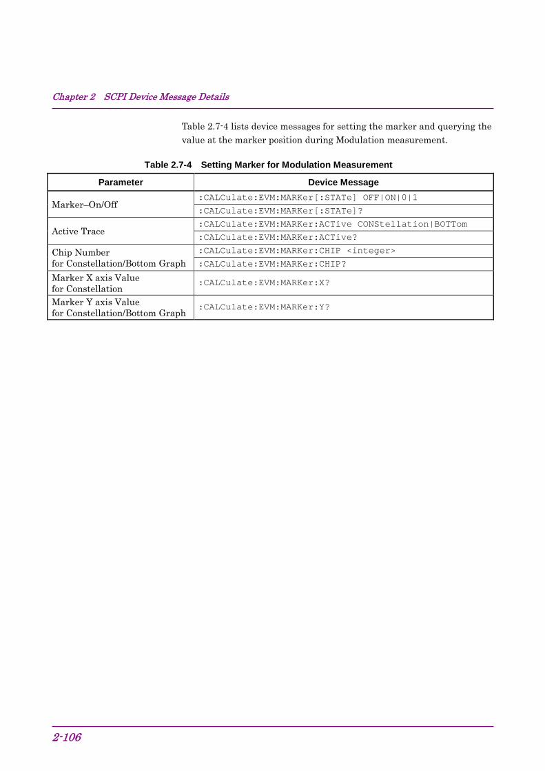
Chapter 2 SCPI Device Message Details
2-106
Table 2.7-4 lists device messages for setting the marker and querying the value at the marker position during Modulation measurement.
Table 2.7-4 Setting Marker for Modulation Measurement
Parameter Device Message
Marker–On/Off :CALCulate:EVM:MARKer[:STATe] OFF|ON|0|1
:CALCulate:EVM:MARKer[:STATe]?
Active Trace :CALCulate:EVM:MARKer:ACTive CONStellation|BOTTom
:CALCulate:EVM:MARKer:ACTive?
Chip Number for Constellation/Bottom Graph
:CALCulate:EVM:MARKer:CHIP <integer>
:CALCulate:EVM:MARKer:CHIP?
Marker X axis Value for Constellation
:CALCulate:EVM:MARKer:X?
Marker Y axis Value for Constellation/Bottom Graph
:CALCulate:EVM:MARKer:Y?

2.7 Modulation Measurement Function
2-107
2
SCPI Device M
essage Details
2.7.1 Measure :CONFigure:EVM Modulation Function
This command selects the Modulation measurement function.
Command
:CONFigure:EVM
Details
No measurement is made.
Example of Use To select the Modulation measurement function. CONF:EVM
Related Command This command has the same function as the following command. :CONFigure:RHO
:CONFigure:RHO Modulation Function
This command selects the Modulation measurement function.
Command
:CONFigure:RHO
Details
No measurement is made.
Example of Use To select the Modulation measurement function. CONF:RHO
Related Command This command has the same function as the following command. :CONFigure:EVM

Chapter 2 SCPI Device Message Details
2-108
:INITiate:EVM Modulation Function
This command executes the Modulation measurement.
Command :INITiate:EVM
Example of Use To execute the Modulation measurement. INIT:EVM
Related Command This command has the same function as the following command. :INITiate:RHO
:INITiate:RHO Modulation Function
This command executes the Modulation measurement.
Command :INITiate:RHO
Example of Use To execute Modulation measurement. INIT:RHO
Related Command This command has the same function as the following command. :INITiate:EVM

2.7 Modulation Measurement Function
2-109
2
SCPI Device M
essage Details
:FETCh:EVM[n]? Modulation Query Function
This command queries the Modulation measurement results.
Query :FETCh:EVM[n]?
Response Refer to Table 2.7-2.
Example of Use To query the Modulation measurement results. FETC:EVM?
Related Command This command has the same function as the following command. :FETCh:RHO[n]?
:FETCh:RHO[n]? Modulation Query Function
This command queries the Modulation measurement results.
Query :FETCh:RHO[n]?
Response Refer to Table 2.7-2.
Example of Use To query the Modulation measurement results. FETC:RHO?
Related Command This command has the same function as the following command. :FETCh:EVM[n]?

Chapter 2 SCPI Device Message Details
2-110
:READ:EVM[n]? Modulation Query Function
This command queries the results after executing single Modulation measurement with the current setting values.
Query :READ:EVM[n]?
Response Refer to Table 2.7-2.
Example of Use To query the results of single Modulation measurement. READ:EVM?
Related Command This command has the same function as the following commands. :MEASure:EVM[n]?
:READ:RHO[n]?
:MEASure:RHO[n]?
:READ:RHO[n]? Modulation Query Function
This command queries the results after executing single Modulation measurement with the current setting values.
Query :READ:RHO[n]?
Response Refer to Table 2.7-2.
Example of Use To query the results of single Modulation measurement. READ:RHO?
Related Command This command has the same function as the following commands. :READ:EVM[n]?
:MEASure:EVM[n]?
:MEASure:RHO[n]?

2.7 Modulation Measurement Function
2-111
2
SCPI Device M
essage Details
:MEASure:EVM[n]? Modulation Query Function
This command queries the results after executing single Modulation measurement with the current setting values.
Query :MEAS:EVM[n]?
Response Refer to Table 2.7-2.
Example of Use To query the results of single Modulation measurement. MEAS:EVM?
Related Command This command has the same function as the following commands. :READ:EVM[n]?
:READ:RHO[n]?
:MEASure:RHO[n]?
:MEASure:RHO[n]? Modulation Query Function
This command queries the results after executing single Modulation measurement with the current setting values.
Query :MEAS:RHO[n]?
Response Refer to Table 2.7-2.
Example of Use To query the results of single Modulation measurement. MEAS:RHO?
Related Command This command has the same function as the following commands. :READ:EVM[n]?
:MEASure:EVM[n]?
:READ:RHO[n]?
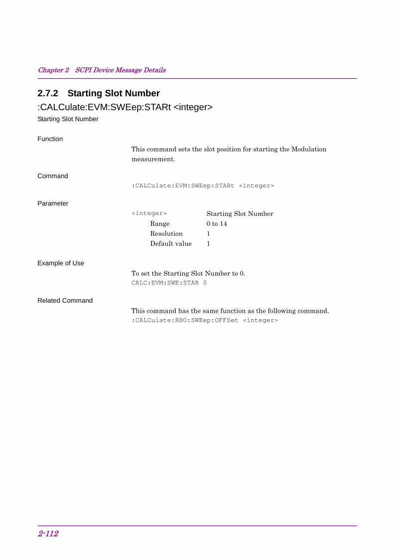
Chapter 2 SCPI Device Message Details
2-112
2.7.2 Starting Slot Number :CALCulate:EVM:SWEep:STARt <integer> Starting Slot Number Function
This command sets the slot position for starting the Modulation measurement.
Command :CALCulate:EVM:SWEep:STARt <integer>
Parameter <integer> Starting Slot Number
Range 0 to 14 Resolution 1 Default value 1
Example of Use
To set the Starting Slot Number to 0. CALC:EVM:SWE:STAR 0
Related Command This command has the same function as the following command. :CALCulate:RHO:SWEep:OFFSet <integer>
2.7 Modulation Measurement Function
2-113
2
SCPI Device M
essage Details
:CALCulate:EVM:SWEep:STARt? Starting Slot Number Query Function
This command queries the Starting Slot Number.
Query :CALCulate:EVM:SWEep:STARt?
Response <integer>
Parameter <integer> Starting Slot Number
Range 0 to 14 Resolution 1
Example of Use
To query the Starting Slot Number. CALC:EVM:SWE:STAR?
> 0
Related Command This command has the same function as the following command. :CALCulate:RHO:SWEep:OFFSet?
Chapter 2 SCPI Device Message Details
2-114
:CALCulate:RHO:SWEep:OFFSet <integer> Starting Slot Number Function
This command sets the slot position for starting the Modulation measurement.
Refer to :CALCulate:EVM:SWEep:STARt <integer>
Related Command This command has the same function as the following command. :CALCulate:EVM:SWEep:STARt <integer>
:CALCulate:RHO:SWEep:OFFSet? Starting Slot Number Query Function
This command queries the Starting Slot Number.
Refer to :CALCulate:EVM:SWEep:STARt?
Related Command This command has the same function as the following command. :CALCulate:EVM:SWEep:STARt?

2.7 Modulation Measurement Function
2-115
2
SCPI Device M
essage Details
2.7.3 Measurement Interval :CALCulate:EVM:SWEep:INTerval <integer> Measurement Interval Function
This command sets the consecutive measurement intervals of the Modulation measurement in slot units.
Command :CALCulate:EVM:SWEep:INTerval <integer>
Parameter <integer> Measurement Interval
Range 1 to 15 – Starting Slot Number Resolution 1 Default value 1
Example of Use
To set the Measurement Interval to 15. CALC:EVM:SWE:INT 15
:CALCulate:EVM:SWEep:INTerval? Measurement Interval Query Function
This command queries the Measurement Interval.
Query :CALCulate:EVM:SWEep:INTerval?
Response <integer>
Parameter <integer> Measurement Interval
Range 1 to 15 – Starting Slot Number Resolution 1
Example of Use
To query the Measurement Interval. CALC:EVM:SWE:INT?
> 15
Chapter 2 SCPI Device Message Details
2-116
2.7.4 Trace Mode :DISPlay:EVM[:VIEW][:SELect] EVM|MAGNitude|PHASe|SUMMary Trace Mode Function
This command sets the type of the graph displayed in the bottom graph window when Modulation measurement is selected.
Command :DISPlay:EVM[:VIEW][:SELect] <mode>
Parameter <mode> Trace Mode
EVM EVM vs Chip (Default value) MAGNitude Mag. Error vs Chip PHASe Phase Error vs Chip SUMMary Summary
Example of Use
To set the Trace Mode to Phase Error vs Chip. DISP:EVM PHAS
:DISPlay:EVM[:VIEW][:SELect]? Trace Mode Query Function
This command queries the type of the graph displayed in the bottom graph window when Modulation measurement is selected.
Query :DISPlay:EVM[:VIEW][:SELect]?
Parameter <mode> Trace Mode
EVM EVM vs Chip MAGN Mag. Error vs Chip PHAS Phase Error vs Chip SUMM Summary
Example of Use
To query the setting of Trace Mode. DISP:EVM?
> PHAS

2.7 Modulation Measurement Function
2-117
2
SCPI Device M
essage Details
2.7.5 Target Slot Number :DISPlay:EVM[:VIEW]:SLOT <integer> Target Slot Number Function
This command sets the slot number of the measured signal to be displayed on the graph.
Command :DISPlay:EVM[:VIEW]:SLOT <integer>
Parameter <integer> Target Slot Number
Range Starting Slot Number to Starting Slot Number + Measurement Interval – 1
Resolution 1 Default value 0
Example of Use
To set the Target Slot Number to 1. DISP:EVM:SLOT 1

Chapter 2 SCPI Device Message Details
2-118
:DISPlay:EVM[:VIEW]:SLOT? Target Slot Number Query Function
This command queries the slot number of the measured signal displayed on the graph.
Query :DISPlay:EVM[:VIEW]:SLOT?
Response <integer>
Parameter <integer> Target Slot Number
Range Starting Slot Number to Starting Slot Number + Measurement Interval – 1
Resolution 1
Example of Use To query the Target Slot Number. DISP:EVM:SLOT?
> 1
2.7 Modulation Measurement Function
2-119
2
SCPI Device M
essage Details
2.7.6 Scale – EVM :DISPlay:EVM[:VIEW]:WINDow2:TRACe:Y[:SCALe]:RLEVel 5|10|20|50 Scale – EVM Function
This command sets the vertical scale of the EVM vs Chip graph. This command can be executed regardless of the selected Trace Mode type.
Command :DISPlay:EVM[:VIEW]:WINDow2:TRACe:Y[:SCALe]:RLEVel <mode>
Parameter <mode> Scale range
5 0 to 5% 10 0 to 10% (Default value) 20 0 to 20% 50 0 to 50%
Example of Use
To set the vertical scale of the EVM vs Chip graph to 10%. DISP:EVM:WIND2:TRAC:Y:RLEV 10
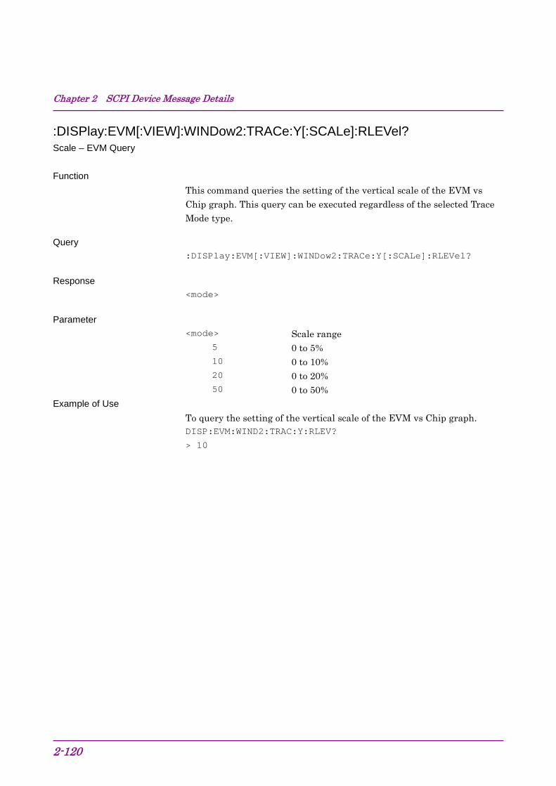
Chapter 2 SCPI Device Message Details
2-120
:DISPlay:EVM[:VIEW]:WINDow2:TRACe:Y[:SCALe]:RLEVel? Scale – EVM Query Function
This command queries the setting of the vertical scale of the EVM vs Chip graph. This query can be executed regardless of the selected Trace Mode type.
Query :DISPlay:EVM[:VIEW]:WINDow2:TRACe:Y[:SCALe]:RLEVel?
Response <mode>
Parameter <mode> Scale range
5 0 to 5% 10 0 to 10% 20 0 to 20% 50 0 to 50%
Example of Use To query the setting of the vertical scale of the EVM vs Chip graph. DISP:EVM:WIND2:TRAC:Y:RLEV?
> 10
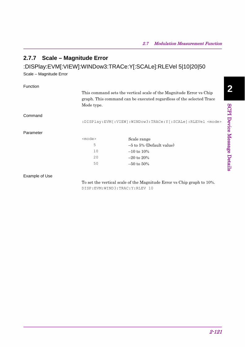
2.7 Modulation Measurement Function
2-121
2
SCPI Device M
essage Details
2.7.7 Scale – Magnitude Error :DISPlay:EVM[:VIEW]:WINDow3:TRACe:Y[:SCALe]:RLEVel 5|10|20|50 Scale – Magnitude Error Function
This command sets the vertical scale of the Magnitude Error vs Chip graph. This command can be executed regardless of the selected Trace Mode type.
Command :DISPlay:EVM[:VIEW]:WINDow3:TRACe:Y[:SCALe]:RLEVel <mode>
Parameter <mode> Scale range
5 –5 to 5% (Default value) 10 –10 to 10% 20 –20 to 20% 50 –50 to 50%
Example of Use
To set the vertical scale of the Magnitude Error vs Chip graph to 10%. DISP:EVM:WIND3:TRAC:Y:RLEV 10

Chapter 2 SCPI Device Message Details
2-122
:DISPlay:EVM[:VIEW]:WINDow3:TRACe:Y[:SCALe]:RLEVel? Scale – Magnitude Error Query Function
This command queries the setting of the vertical scale of the Magnitude Error vs Chip graph. This query can be executed regardless of the selected Trace Mode type.
Query :DISPlay:EVM[:VIEW]:WINDow3:TRACe:Y[:SCALe]:RLEVel?
Response <mode>
Parameter <mode> Scale range
5 –5 to 5% 10 –10 to 10% 20 –20 to 20% 50 –50 to 50%
Example of Use
To query the setting of the vertical scale of the Magnitude Error vs Chip graph. DISP:EVM:WIND3:TRAC:Y:RLEV?
> 10

2.7 Modulation Measurement Function
2-123
2
SCPI Device M
essage Details
2.7.8 Scale – Phase Error :DISPlay:EVM[:VIEW]:WINDow4:TRACe:Y[:SCALe]:RLEVel 5|10|20|50 Scale – Phase Error Function
This command sets the vertical scale of the Phase Error vs Chip graph. This command can be executed regardless of the selected Trace Mode type.
Command :DISPlay:EVM[:VIEW]:WINDow4:TRACe:Y[:SCALe]:RLEVel <mode>
Parameter <mode> Scale range
5 –5 to 5 degree (Default value) 10 –10 to 10 degree 20 –20 to 20 degree 50 –50 to 50 degree
Example of Use To set the vertical scale of the Phase Error vs Chip graph to 10 degree. DISP:EVM:WIND4:TRAC:Y:RLEV 10
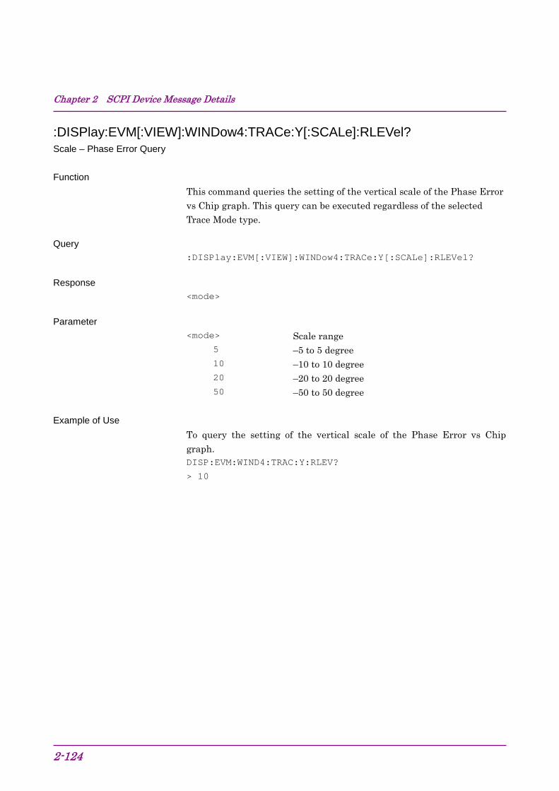
Chapter 2 SCPI Device Message Details
2-124
:DISPlay:EVM[:VIEW]:WINDow4:TRACe:Y[:SCALe]:RLEVel? Scale – Phase Error Query Function
This command queries the setting of the vertical scale of the Phase Error vs Chip graph. This query can be executed regardless of the selected Trace Mode type.
Query :DISPlay:EVM[:VIEW]:WINDow4:TRACe:Y[:SCALe]:RLEVel?
Response <mode>
Parameter <mode> Scale range
5 –5 to 5 degree 10 –10 to 10 degree 20 –20 to 20 degree 50 –50 to 50 degree
Example of Use
To query the setting of the vertical scale of the Phase Error vs Chip graph. DISP:EVM:WIND4:TRAC:Y:RLEV?
> 10

2.7 Modulation Measurement Function
2-125
2
SCPI Device M
essage Details
2.7.9 Storage Mode [:SENSe]:EVM:AVERage[:STATe] OFF|ON|AMAXimum|0|1|2 Storage Mode Function
This command sets the Storage Mode.
Command [:SENSe]:EVM:AVERage[:STATe] <mode>
Parameter <mode> Storage Mode
OFF|0 Off (Default value) ON|1 Average AMAXimum|2 Average & Max
Example of Use
To set the Storage Mode to Average. EVM:AVER ON
Related Command This command has the same function as the following command. [:SENSe]:RHO:AVERage[:STATe] OFF|ON|AMAXimum|0|1|2

Chapter 2 SCPI Device Message Details
2-126
[:SENSe]:EVM:AVERage[:STATe]? Storage Mode Query Function
This command queries the setting of Storage Mode.
Query [:SENSe]:EVM:AVERage[:STATe]?
Response <mode>
Parameter <mode> Storage Mode
0 Off 1 Average 2 Average & Max
Example of Use
To query the setting of Storage Mode. EVM:AVER?
> 1
Related Command This command has the same function as the following command. [:SENSe]:RHO:AVERage[:STATe]?
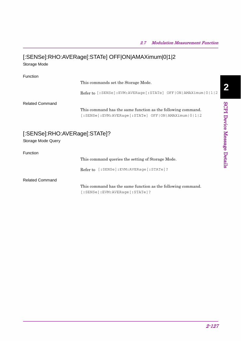
2.7 Modulation Measurement Function
2-127
2
SCPI Device M
essage Details
[:SENSe]:RHO:AVERage[:STATe] OFF|ON|AMAXimum|0|1|2 Storage Mode Function
This commands set the Storage Mode.
Refer to [:SENSe]:EVM:AVERage[:STATe] OFF|ON|AMAXimum|0|1|2
Related Command This command has the same function as the following command. [:SENSe]:EVM:AVERage[:STATe] OFF|ON|AMAXimum|0|1|2
[:SENSe]:RHO:AVERage[:STATe]? Storage Mode Query Function
This command queries the setting of Storage Mode.
Refer to [:SENSe]:EVM:AVERage[:STATe]?
Related Command This command has the same function as the following command. [:SENSe]:EVM:AVERage[:STATe]?

Chapter 2 SCPI Device Message Details
2-128
2.7.10 Storage Count [:SENSe]:EVM:AVERage:COUNt <integer> Storage Count Function
This command sets the number of averaging times (Storage Count) for the Modulation measurement.
Command [:SENSe]:EVM:AVERage:COUNt <integer>
Parameter <integer> Storage Count
Range 2 to 9999 Resolution 1 Default value 2
Example of Use To set the Storage Count to 10. EVM:AVER:COUN 10
Related Command This command has the same function as the following command. [:SENSe]:RHO:AVERage:COUNt <integer>

2.7 Modulation Measurement Function
2-129
2
SCPI Device M
essage Details
[:SENSe]:EVM:AVERage:COUNt? Storage Count Query Function
This command queries the Storage Count of the Modulation measurement.
Query [:SENSe]:EVM:AVERage:COUNt?
Response <integer>
Parameter <integer> Storage Count
Range 2 to 9999 Resolution 1
Example of Use To query the Storage Count. EVM:AVER:COUN?
> 10
Related Command This command has the same function as the following command. [:SENSe]:RHO:AVERage:COUNt?

Chapter 2 SCPI Device Message Details
2-130
[:SENSe]:RHO:AVERage:COUNt <integer> Storage Count Function
This command sets the number of averaging times (Storage Count) for the Modulation measurement.
Refer to [:SENSe]:EVM:AVERage:COUNt <integer>
Related Command This command has the same function as the following command. [:SENSe]:EVM:AVERage:COUNt <integer>
[:SENSe]:RHO:AVERage:COUNt? Storage Count Query Function
This command queries the Storage Count of the Modulation measurement.
Refer to [:SENSe]:EVM:AVERage:COUNt?
Related Command This command has the same function as the following command. [:SENSe]:EVM:AVERage:COUNt?

2.7 Modulation Measurement Function
2-131
2
SCPI Device M
essage Details
2.7.11 Display Page :DISPlay:EVM[:VIEW]:WINDow7:PAGE:NUMBer <integer> Target Page Number Function
This command sets the page number of the displayed Summary. Command
:DISPlay:EVM[:VIEW]:WINDow7:PAGE:NUMBer <integer>
Parameter <integer> Page number
Range 1 to 2 Resolution 1 Suffix code None Default value 0
Example of Use To set the page number of the displayed Summary to 1. DISP:EVM:WIND7:PAGE:NUMB 1
:DISPlay:EVM[:VIEW]:WINDow7:PAGE:NUMBer? Target Page Number Query Function
This command queries the page number of the displayed Summary. Query
:DISPlay:EVM[:VIEW]:WINDow7:PAGE:NUMBer?
Response <integer>
Parameter <integer> Page number
Range 1 to 2 Resolution 1
Example of Use To query the page number of the displayed Summary. DISP:EVM:WIND7:PAGE:NUMB?
> 1

Chapter 2 SCPI Device Message Details
2-132
2.7.12 Marker – On/Off :CALCulate:EVM:MARKer[:STATe] OFF|ON|0|1 Marker – On/Off Function
This command sets the marker display On/Off when Modulation measurement is selected.
Command :CALCulate:EVM:MARKer[:STATe] <switch>
Parameter <switch> Marker
0|OFF Off 1|ON On (Default value)
Example of Use
To display the marker. CALC:EVM:MARK 1
:CALCulate:EVM:MARKer[:STATe]? Marker – On/Off Query Function
This command queries the marker display On/Off when Modulation measurement is selected.
Query :CALCulate:EVM:MARKer[:STATe]?
Response <switch>
Parameter <switch> Marker
0 Off 1 On
Example of Use
To query the setting of Marker. CALC:EVM:MARK?
> 1
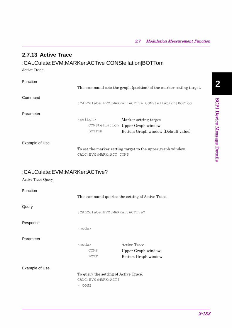
2.7 Modulation Measurement Function
2-133
2
SCPI Device M
essage Details
2.7.13 Active Trace :CALCulate:EVM:MARKer:ACTive CONStellation|BOTTom Active Trace Function
This command sets the graph (position) of the marker setting target.
Command :CALCulate:EVM:MARKer:ACTive CONStellation|BOTTom
Parameter <switch> Marker setting target
CONStellation Upper Graph window BOTTom Bottom Graph window (Default value)
Example of Use
To set the marker setting target to the upper graph window. CALC:EVM:MARK:ACT CONS
:CALCulate:EVM:MARKer:ACTive? Active Trace Query Function
This command queries the setting of Active Trace.
Query :CALCulate:EVM:MARKer:ACTive?
Response <mode>
Parameter <mode> Active Trace
CONS Upper Graph window BOTT Bottom Graph window
Example of Use
To query the setting of Active Trace. CALC:EVM:MARK:ACT?
> CONS

Chapter 2 SCPI Device Message Details
2-134
2.7.14 Chip Number :CALCulate:EVM:MARKer:CHIP <integer> Chip Number Function
This command sets in chip units the marker position on the graph displayed in the upper or bottom graph window. The setting target graph can be set by Active Trace.
Command :CALCulate:EVM:MARKer:CHIP <integer>
Parameter <integer> Chip number
Range 0 to 2559 Resolution 1 Default value 0
Example of Use
To set the marker position to 10. CALC:EVM:MARK:CHIP 10

2.7 Modulation Measurement Function
2-135
2
SCPI Device M
essage Details
:CALCulate:EVM:MARKer:CHIP? Chip Number Query Function
This command queries in chip units the marker position on the graph displayed in the upper or bottom graph window. The querying target graph can be set by Active Trace.
Query :CALCulate:EVM:MARKer:CHIP?
Response <integer>
Parameter <integer> Chip number
Range 0 to 2559 Resolution 1
Example of Use
To query the setting of Marker Number. CALC:EVM:MARK:CHIP?
> 10
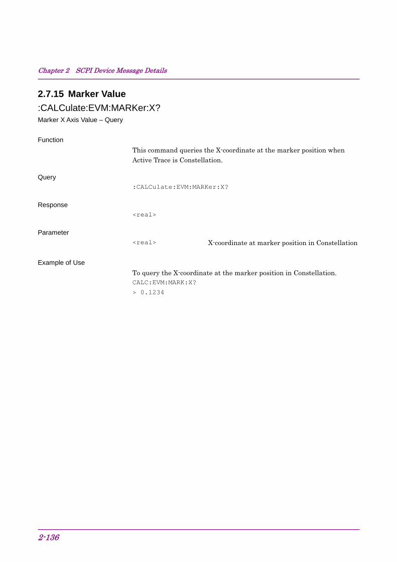
Chapter 2 SCPI Device Message Details
2-136
2.7.15 Marker Value :CALCulate:EVM:MARKer:X? Marker X Axis Value – Query Function
This command queries the X-coordinate at the marker position when Active Trace is Constellation.
Query :CALCulate:EVM:MARKer:X?
Response <real>
Parameter <real> X-coordinate at marker position in Constellation
Example of Use To query the X-coordinate at the marker position in Constellation. CALC:EVM:MARK:X?
> 0.1234

2.7 Modulation Measurement Function
2-137
2
SCPI Device M
essage Details
:CALCulate:EVM:MARKer:Y? Marker Y Axis Value – Query Function
This command queries the Y-coordinate at the marker position in the graph targeted for Active Trace setting.
Query :CALCulate:EVM:MARKer:Y?
Response <real>
Parameter <real> Y-coordinate at marker position in graph
When Active Trace is Constellation: Constellation No unit When Active Trace is Bottom and Trace Mode is EVM vs Chip: EVM Unit: % When Active Trace is Bottom and Trace Mode is Mag.Error vs Chip: Magnitude Error Unit: % When Active Trace is Bottom and Trace Mode is Phase Error vs Chip: Phase Error Unit: degree
Example of Use
To query the Y-coordinate at the marker position. CALC:EVM:MARK:Y?
> 0.12

Chapter 2 SCPI Device Message Details
2-138
2.8 Code Domain measurement function This section describes device messages for the Code Domain measurement functions.
Table 2.8-1 lists device messages to execute the Code Domain measurement and to query the result.
Table 2.8-1 Code Domain Measurement Function
Function Device Message Configure :CONFigure:CDPower
Initiate :INITiate:CDPower
Fetch :FETCh:CDPower[n]?
Read :READ:CDPower[n]?
Measure :MEASure:CDPower[n]?
Table 2.8-2 lists the responses to parameter n in Table 2.8-1.

2.8 Code Domain measurement function
2-139
2
SCPI Device M
essage Details
Table 2.8-2 Responses to Code Domain Measurement Results
n Result Mode Response
1 or omitted
A
Returns the measurement results with comma separated value in the following order: 1. EVM(RMS) [%] 2. EVM(Peak) [%] 3. Magnitude Error [%] 4. Phase Error [%] 5. Code Power [dB] 6. Number of detected SF 7. Number of channelization code number for detected SF 8. Modulation type for detected SF QPSK QPSK 16Q 16QAM 64Q 64QAM NONE Inactive channel 9. Mean Power [dBm] 10. P−CPICH Power [dB] 11. P−SCH Power [dB] 12. S−SCH Power [dB] 13. Total Active Power [dB]
B
Returns the measurement results with comma separated value in the following order: 1. EVM(RMS) [%] 2. EVM(Peak) [%] 3. Magnitude Error [%] 4. Phase Error [%] 5. Mean Power [dBm] 6. Code Power [dB] 7. to 10. –999.0 11. Total Active Power [dB] 12. P−CPICH Power [dB] 13. to 27. –999.0 28. P−SCH Power [dB] 29. S−SCH Power [dB] 30. to 44. –999.0
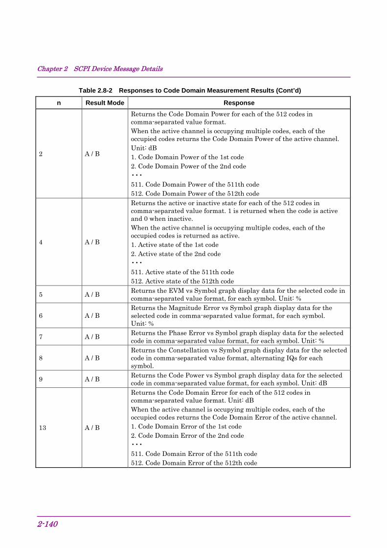
Chapter 2 SCPI Device Message Details
2-140
Table 2.8-2 Responses to Code Domain Measurement Results (Cont’d)
n Result Mode Response
2 A / B
Returns the Code Domain Power for each of the 512 codes in comma-separated value format. When the active channel is occupying multiple codes, each of the occupied codes returns the Code Domain Power of the active channel. Unit: dB 1. Code Domain Power of the 1st code 2. Code Domain Power of the 2nd code ••• 511. Code Domain Power of the 511th code 512. Code Domain Power of the 512th code
4 A / B
Returns the active or inactive state for each of the 512 codes in comma-separated value format. 1 is returned when the code is active and 0 when inactive. When the active channel is occupying multiple codes, each of the occupied codes is returned as active. 1. Active state of the 1st code 2. Active state of the 2nd code ••• 511. Active state of the 511th code 512. Active state of the 512th code
5 A / B Returns the EVM vs Symbol graph display data for the selected code in comma-separated value format, for each symbol. Unit: %
6 A / B Returns the Magnitude Error vs Symbol graph display data for the selected code in comma-separated value format, for each symbol. Unit: %
7 A / B Returns the Phase Error vs Symbol graph display data for the selected code in comma-separated value format, for each symbol. Unit: %
8 A / B Returns the Constellation vs Symbol graph display data for the selected code in comma-separated value format, alternating IQs for each symbol.
9 A / B Returns the Code Power vs Symbol graph display data for the selected code in comma-separated value format, for each symbol. Unit: dB
13 A / B
Returns the Code Domain Error for each of the 512 codes in comma-separated value format. Unit: dB When the active channel is occupying multiple codes, each of the occupied codes returns the Code Domain Error of the active channel. 1. Code Domain Error of the 1st code 2. Code Domain Error of the 2nd code ••• 511. Code Domain Error of the 511th code 512. Code Domain Error of the 512th code
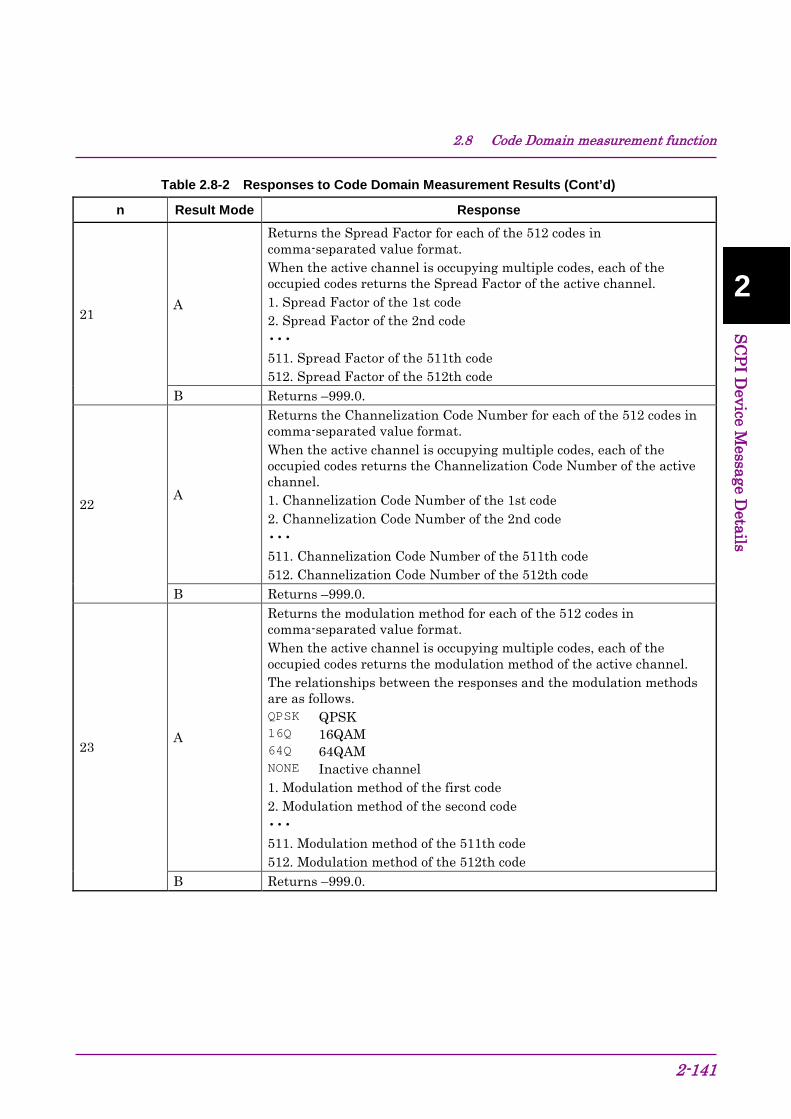
2.8 Code Domain measurement function
2-141
2
SCPI Device M
essage Details
Table 2.8-2 Responses to Code Domain Measurement Results (Cont’d)
n Result Mode Response
21 A
Returns the Spread Factor for each of the 512 codes in comma-separated value format. When the active channel is occupying multiple codes, each of the occupied codes returns the Spread Factor of the active channel. 1. Spread Factor of the 1st code 2. Spread Factor of the 2nd code ••• 511. Spread Factor of the 511th code 512. Spread Factor of the 512th code
B Returns –999.0.
22 A
Returns the Channelization Code Number for each of the 512 codes in comma-separated value format. When the active channel is occupying multiple codes, each of the occupied codes returns the Channelization Code Number of the active channel. 1. Channelization Code Number of the 1st code 2. Channelization Code Number of the 2nd code ••• 511. Channelization Code Number of the 511th code 512. Channelization Code Number of the 512th code
B Returns –999.0.
23 A
Returns the modulation method for each of the 512 codes in comma-separated value format. When the active channel is occupying multiple codes, each of the occupied codes returns the modulation method of the active channel. The relationships between the responses and the modulation methods are as follows. QPSK QPSK 16Q 16QAM 64Q 64QAM NONE Inactive channel 1. Modulation method of the first code 2. Modulation method of the second code ••• 511. Modulation method of the 511th code 512. Modulation method of the 512th code
B Returns –999.0.
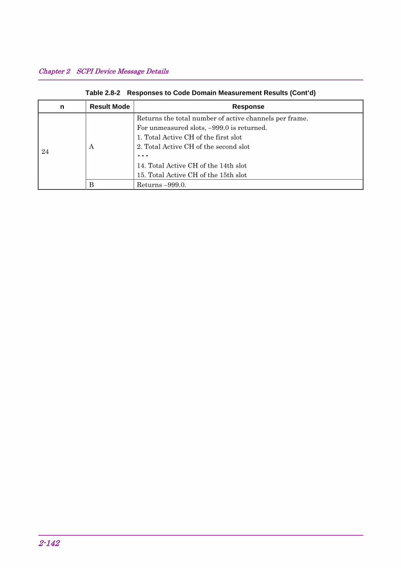
Chapter 2 SCPI Device Message Details
2-142
Table 2.8-2 Responses to Code Domain Measurement Results (Cont’d)
n Result Mode Response
24 A
Returns the total number of active channels per frame. For unmeasured slots, −999.0 is returned. 1. Total Active CH of the first slot 2. Total Active CH of the second slot ••• 14. Total Active CH of the 14th slot 15. Total Active CH of the 15th slot
B Returns –999.0.
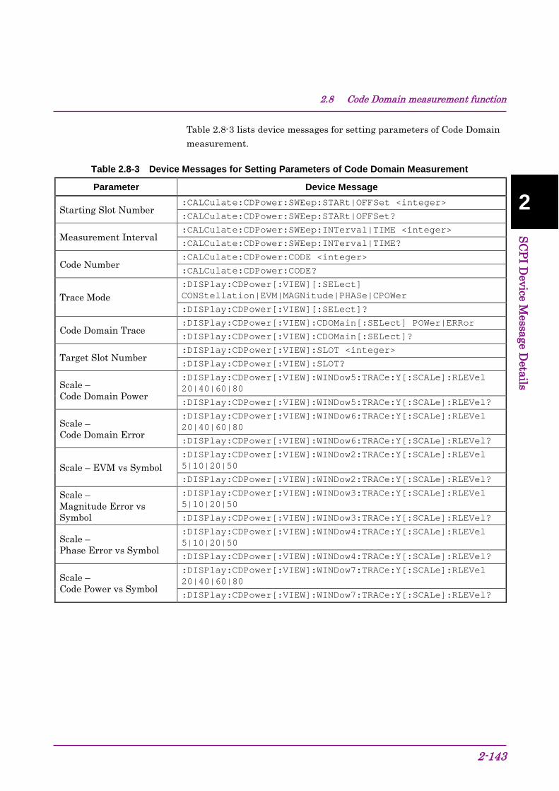
2.8 Code Domain measurement function
2-143
2
SCPI Device M
essage Details
Table 2.8-3 lists device messages for setting parameters of Code Domain measurement.
Table 2.8-3 Device Messages for Setting Parameters of Code Domain Measurement
Parameter Device Message
Starting Slot Number :CALCulate:CDPower:SWEep:STARt|OFFSet <integer>
:CALCulate:CDPower:SWEep:STARt|OFFSet?
Measurement Interval :CALCulate:CDPower:SWEep:INTerval|TIME <integer>
:CALCulate:CDPower:SWEep:INTerval|TIME?
Code Number :CALCulate:CDPower:CODE <integer>
:CALCulate:CDPower:CODE?
Trace Mode :DISPlay:CDPower[:VIEW][:SELect] CONStellation|EVM|MAGNitude|PHASe|CPOWer
:DISPlay:CDPower[:VIEW][:SELect]?
Code Domain Trace :DISPlay:CDPower[:VIEW]:CDOMain[:SELect] POWer|ERRor
:DISPlay:CDPower[:VIEW]:CDOMain[:SELect]?
Target Slot Number :DISPlay:CDPower[:VIEW]:SLOT <integer>
:DISPlay:CDPower[:VIEW]:SLOT?
Scale – Code Domain Power
:DISPlay:CDPower[:VIEW]:WINDow5:TRACe:Y[:SCALe]:RLEVel 20|40|60|80
:DISPlay:CDPower[:VIEW]:WINDow5:TRACe:Y[:SCALe]:RLEVel?
Scale – Code Domain Error
:DISPlay:CDPower[:VIEW]:WINDow6:TRACe:Y[:SCALe]:RLEVel 20|40|60|80
:DISPlay:CDPower[:VIEW]:WINDow6:TRACe:Y[:SCALe]:RLEVel?
Scale – EVM vs Symbol :DISPlay:CDPower[:VIEW]:WINDow2:TRACe:Y[:SCALe]:RLEVel 5|10|20|50
:DISPlay:CDPower[:VIEW]:WINDow2:TRACe:Y[:SCALe]:RLEVel?
Scale – Magnitude Error vs Symbol
:DISPlay:CDPower[:VIEW]:WINDow3:TRACe:Y[:SCALe]:RLEVel 5|10|20|50
:DISPlay:CDPower[:VIEW]:WINDow3:TRACe:Y[:SCALe]:RLEVel?
Scale – Phase Error vs Symbol
:DISPlay:CDPower[:VIEW]:WINDow4:TRACe:Y[:SCALe]:RLEVel 5|10|20|50
:DISPlay:CDPower[:VIEW]:WINDow4:TRACe:Y[:SCALe]:RLEVel?
Scale – Code Power vs Symbol
:DISPlay:CDPower[:VIEW]:WINDow7:TRACe:Y[:SCALe]:RLEVel 20|40|60|80
:DISPlay:CDPower[:VIEW]:WINDow7:TRACe:Y[:SCALe]:RLEVel?
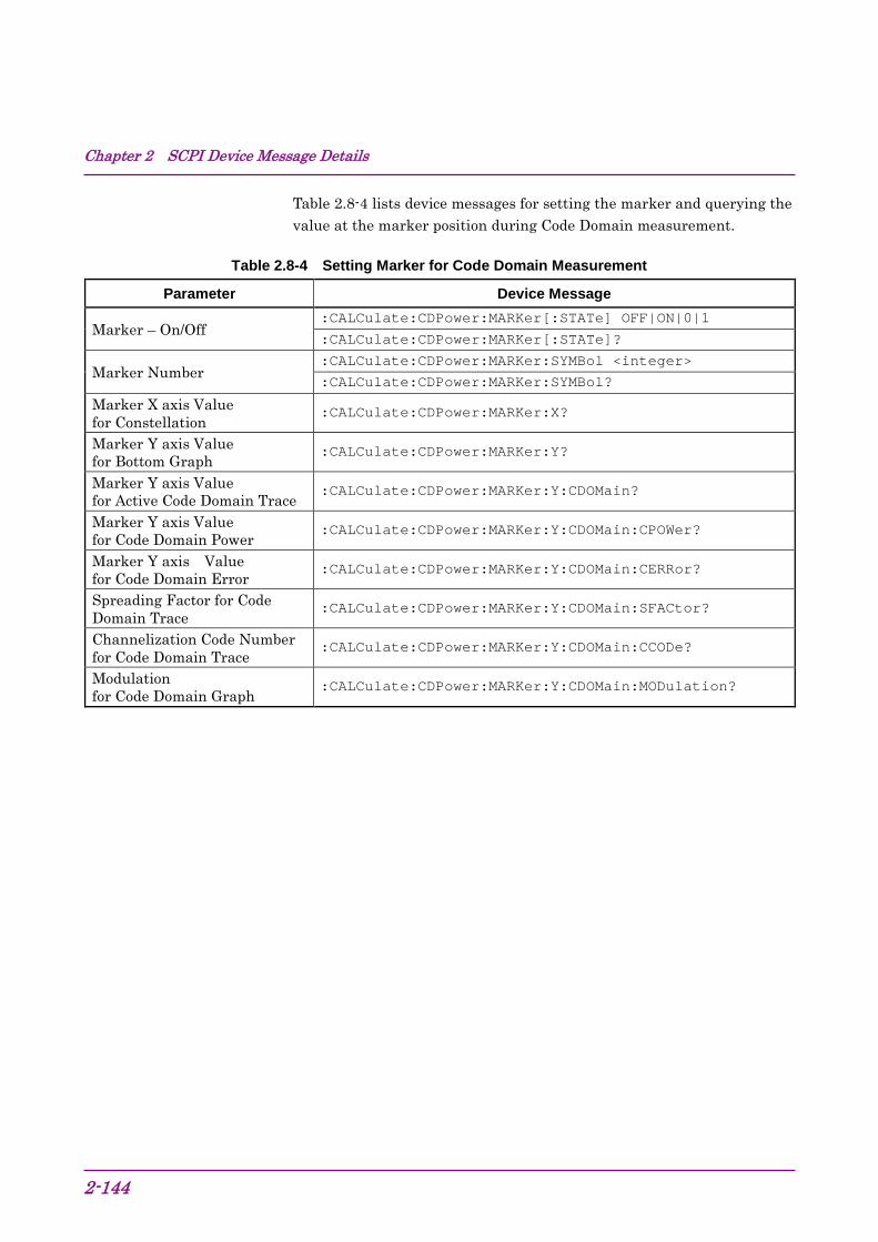
Chapter 2 SCPI Device Message Details
2-144
Table 2.8-4 lists device messages for setting the marker and querying the value at the marker position during Code Domain measurement.
Table 2.8-4 Setting Marker for Code Domain Measurement
Parameter Device Message
Marker – On/Off :CALCulate:CDPower:MARKer[:STATe] OFF|ON|0|1
:CALCulate:CDPower:MARKer[:STATe]?
Marker Number :CALCulate:CDPower:MARKer:SYMBol <integer>
:CALCulate:CDPower:MARKer:SYMBol?
Marker X axis Value for Constellation
:CALCulate:CDPower:MARKer:X?
Marker Y axis Value for Bottom Graph
:CALCulate:CDPower:MARKer:Y?
Marker Y axis Value for Active Code Domain Trace
:CALCulate:CDPower:MARKer:Y:CDOMain?
Marker Y axis Value for Code Domain Power
:CALCulate:CDPower:MARKer:Y:CDOMain:CPOWer?
Marker Y axis Value for Code Domain Error
:CALCulate:CDPower:MARKer:Y:CDOMain:CERRor?
Spreading Factor for Code Domain Trace
:CALCulate:CDPower:MARKer:Y:CDOMain:SFACtor?
Channelization Code Number for Code Domain Trace
:CALCulate:CDPower:MARKer:Y:CDOMain:CCODe?
Modulation for Code Domain Graph
:CALCulate:CDPower:MARKer:Y:CDOMain:MODulation?
2.8 Code Domain measurement function
2-145
2
SCPI Device M
essage Details
2.8.1 Measure :CONFigure:CDPower Code Domain Function
This command selects the Code Domain measurement function.
Command :CONFigure:CDPower
Details No measurement is made.
Example of Use To select the Code Domain measurement function. CONF:CDP
:INITiate:CDPower Code Domain Function
This command executes the Code Domain measurement.
Command :INITiate:CDPower
Example of Use To execute the Code Domain measurement. INIT:CDP
Chapter 2 SCPI Device Message Details
2-146
:FETCh:CDPower[n]? Code Domain Query Function
This command queries the Code Domain measurement results.
Query :FETCh:CDPower[n]?
Response Refer to Table 2.8-2.
Example of Use To query the Code Domain measurement results. FETC:CDP?
:READ:CDPower[n]? Code Domain Query Function
This command queries the results after executing single Code Domain measurement with the current setting values.
Query :READ:CDPower[n]?
Response Refer to Table 2.8-2.
Example of Use To query the results of single Code Domain measurement. READ:CDP?
Related Command This command has the same function as the following command. :MEASure:CDPower[n]?

2.8 Code Domain measurement function
2-147
2
SCPI Device M
essage Details
:MEASure:CDPower[n]? Code Domain Query Function
This command queries the results after executing single Code Domain measurement with the current setting values.
Refer to :READ:CDPower[n]?
Related Command This command has the same function as the following command. :READ:CDPower[n]?
Chapter 2 SCPI Device Message Details
2-148
2.8.2 Starting Slot Number :CALCulate:CDPower:SWEep:STARt|OFFSet <integer> Starting Slot Number Function
This command sets the slot position for starting the Code Domain measurement.
Command :CALCulate:CDPower:SWEep:STARt|OFFSet <integer>
Parameter <integer> Starting Slot Number
Range 0 to 14 Resolution 1 Default value 1
Example of Use
To set the Starting Slot Number to 14. CALC:CDP:SWE:STAR 14
:CALCulate:CDPower:SWEep:STARt|OFFSet? Starting Slot Number Query Function
This command queries the Starting Slot Number.
Query :CALCulate:CDPower:SWEep:STARt|OFFSet?
Response <integer>
Parameter <integer> Starting Slot Number
Range 0 to 14 Resolution 1
Example of Use
To query the Starting Slot Number. CALC:CDP:SWE:STAR?
> 14

2.8 Code Domain measurement function
2-149
2
SCPI Device M
essage Details
2.8.3 Measurement Interval :CALCulate:CDPower:SWEep:INTerval|TIME <integer> Measurement Interval Function
This command sets the consecutive measurement intervals of the Code Domain measurement in slot units.
Command :CALCulate:CDPower:SWEep:INTerval|TIME <integer>
Parameter <integer> Measurement Interval
Range 1 to 15 – Starting Slot Number Resolution 1 Default value 1
Example of Use
To set the Measurement Interval to 15. CALC:CDP:SWE:INT 15
:CALCulate:CDPower:SWEep:INTerval|TIME? Measurement Interval Query Function
This command queries the Measurement Interval.
Query :CALCulate:CDPower:SWEep:INTerval|TIME?
Response <integer>
Parameter <integer> Measurement Interval
Range 1 to 15 – Starting Slot Number Resolution 1
Example of Use
To query the Measurement Interval. CALC:CDP:SWE:INT?
> 15
Chapter 2 SCPI Device Message Details
2-150
2.8.4 Code Number :CALCulate:CDPower:CODE <integer> Code Number Function
This command sets the code number targeted for analysis and display.
Command :CALCulate:CDPower:CODE <integer>
Parameter <integer> Code Number
Range 0 to 511 Resolution 1 Default value 0
Example of Use
To set the Code Number to 16. CALC:CDP:CODE 16
:CALCulate:CDPower:CODE? Code Number – Query Function
This command queries the code number targeted for analysis and display.
Query :CALCulate:CDPower:CODE?
Parameter <integer> Code Number
Range 0 to 511 Resolution 1
Example of Use
To query the Code Number. CALC:CDP:CODE?
> 16

2.8 Code Domain measurement function
2-151
2
SCPI Device M
essage Details
2.8.5 Trace Mode :DISPlay:CDPower[:VIEW][:SELect] CONStellation|EVM|MAGNitude|PHASe |CPOWer Trace Mode Function
This command sets the type of the graph displayed in the bottom graph window when Code Domain measurement is selected.
Command :DISPlay:CDPower[:VIEW][:SELect] <mode>
Parameter <mode> Trace Mode
CONStellation Constellation EVM EVM vs Symbol MAGNitude Magnitude Error vs Symbol PHASe Phase Error vs Symbol CPOWer Code Power vs Symbol (Default value)
Example of Use To set the Trace Mode to Code Power vs Symbol. DISP:CDP CPOW

Chapter 2 SCPI Device Message Details
2-152
:DISPlay:CDPower[:VIEW][:SELect]? Trace Mode Query Function
This command queries the type of the graph displayed in the bottom graph window when Code Domain measurement is selected.
Query :DISPlay:CDPower[:VIEW][:SELect]?
Response <mode>
Parameter <mode> Trace Mode
CONS Constellation EVM EVM vs. Symbol MAGN Magnitude Error vs Symbol PHAS Phase Error vs Symbol CPOW Code Power vs Symbol
Example of Use To query the Trace Mode. DISP:CDP?
> CPOW

2.8 Code Domain measurement function
2-153
2
SCPI Device M
essage Details
2.8.6 Code Domain Trace :DISPlay:CDPower[:VIEW]:CDOMain[:SELect] POWer|ERRor Code Domain Trace Function
This command sets the type of the graph displayed in the upper graph window when Code Domain measurement is selected.
Command :DISPlay:CDPower[:VIEW]:CDOMain[:SELect] <mode>
Parameter <mode> Trace Mode
POWer Code Domain Power (Default value) ERRor Code Domain Error
Example of Use
To set the Trace Mode to Code Domain Error. DISP:CDP:CDOM ERR
:DISPlay:CDPower[:VIEW]:CDOMain[:SELect]? Code Domain Trace Query Function
This command queries the type of the graph displayed in the upper graph window when Code Domain measurement is selected.
Query :DISPlay:CDPower[:VIEW]:CDOMain[:SELect]?
Response <mode>
Parameter <mode> Trace Mode
POW Code Domain Power ERR Code Domain Error
Example of Use
To query the Trace Mode. DISP:CDP:CDOM?
> ERR
Chapter 2 SCPI Device Message Details
2-154
2.8.7 Target Slot Number :DISPlay:CDPower[:VIEW]:SLOT <integer> Target Slot Number Function
This command sets the slot number of the measured signal to be displayed on the graph.
Command :DISPlay:CDPower[:VIEW]:SLOT <integer>
Parameter <integer> Target Slot Number
Range Starting Slot Number to Starting Slot Number + Measurement Interval – 1
Resolution 1 Default value 0
Example of Use
To set the Target Slot Number to 1. DISP:CDP:SLOT 1
:DISPlay:CDPower[:VIEW]:SLOT? Target Slot Number Query Function
This command queries the slot number of the measured signal displayed on the graph.
Query :DISPlay:CDPower[:VIEW]:SLOT?
Response <integer>
Parameter <integer> Target Slot Number
Range Starting Slot Number to Starting Slot Number + Measurement Interval – 1
Resolution 1 Example of Use
To query the Target Slot Number. DISP:CDP:SLOT?
> 1

2.8 Code Domain measurement function
2-155
2
SCPI Device M
essage Details
2.8.8 Scale – Code Domain Power :DISPlay:CDPower[:VIEW]:WINDow5:TRACe:Y[:SCALe]:RLEVel 20|40|60|80 Scale – Code Domain Power Function
This command sets the vertical scale of the Code Domain Power graph. The reference position (uppermost scale) is always 0 dB. This command can be executed regardless of the selected Trace Mode type.
Command :DISPlay:CDPower[:VIEW]:WINDow5:TRACe:Y[:SCALe]:RLEVel
<mode>
Parameter <mode> Scale range
20 –20 to 0 dB 40 –40 to 0 dB 60 –60 to 0 dB 80 –80 to 0 dB (Default value)
Example of Use To set the vertical scale of the Code Domain Power graph to 60 dB. DISP:CDP:WIND5:TRAC:Y:RLEV 60

Chapter 2 SCPI Device Message Details
2-156
:DISPlay:CDPower[:VIEW]:WINDow5:TRACe:Y[:SCALe]:RLEVel? Scale – Code Domain Power Query Function
This command queries the setting of the vertical scale of the Code Domain Power graph. The reference position (uppermost scale) is always 0 dB. This query can be executed regardless of the selected Trace Mode type.
Query :DISPlay:CDPower[:VIEW]:WINDow5:TRACe:Y[:SCALe]:RLEVel?
Response <mode>
Parameter <mode> Scale range
20 –20 to 0 dB 40 –40 to 0 dB 60 –60 to 0 dB 80 –80 to 0 dB
Example of Use To query the setting of the vertical scale of the Code Domain Power graph. DISP:CDP:WIND5:TRAC:Y:RLEV?
> 60

2.8 Code Domain measurement function
2-157
2
SCPI Device M
essage Details
2.8.9 Scale – Code Domain Error :DISPlay:CDPower[:VIEW]:WINDow6:TRACe:Y[:SCALe]:RLEVel 20|40|60|80 Scale – Code Domain Error Function
This command sets the vertical scale of the Code Domain Error graph. The reference position (lowermost scale) is always –80 dB. This command can be executed regardless of the selected Trace Mode type.
Command :DISPlay:CDPower[:VIEW]:WINDow6:TRACe:Y[:SCALe]:RLEVel
<mode>
Parameter <mode> Scale range
20 –80 to –60 dB 40 –80 to –40 dB 60 –80 to –20 dB 80 –80 to 0 dB (Default value)
Example of Use To set the vertical scale of the Code Domain Error graph to 20 dB. DISP:CDP:WIND6:TRAC:Y:RLEV 20

Chapter 2 SCPI Device Message Details
2-158
:DISPlay:CDPower[:VIEW]:WINDow6:TRACe:Y[:SCALe]:RLEVel? Scale – Code Domain Error Query Function
This command queries the setting of the vertical scale of the Code Domain Error graph. The reference position (lowermost scale) is always –80 dB. This query can be executed regardless of the selected Trace Mode type.
Query :DISPlay:CDPower[:VIEW]:WINDow6:TRACe:Y[:SCALe]:RLEVel?
Response <mode>
Parameter <mode> Scale range
20 –80 to –60 dB 40 –80 to –40 dB 60 –80 to –20 dB 80 –80 to 0 dB
Example of Use To query the setting of the vertical scale of the Code Domain Error graph. DISP:CDP:WIND6:TRAC:Y:RLEV?
> 20
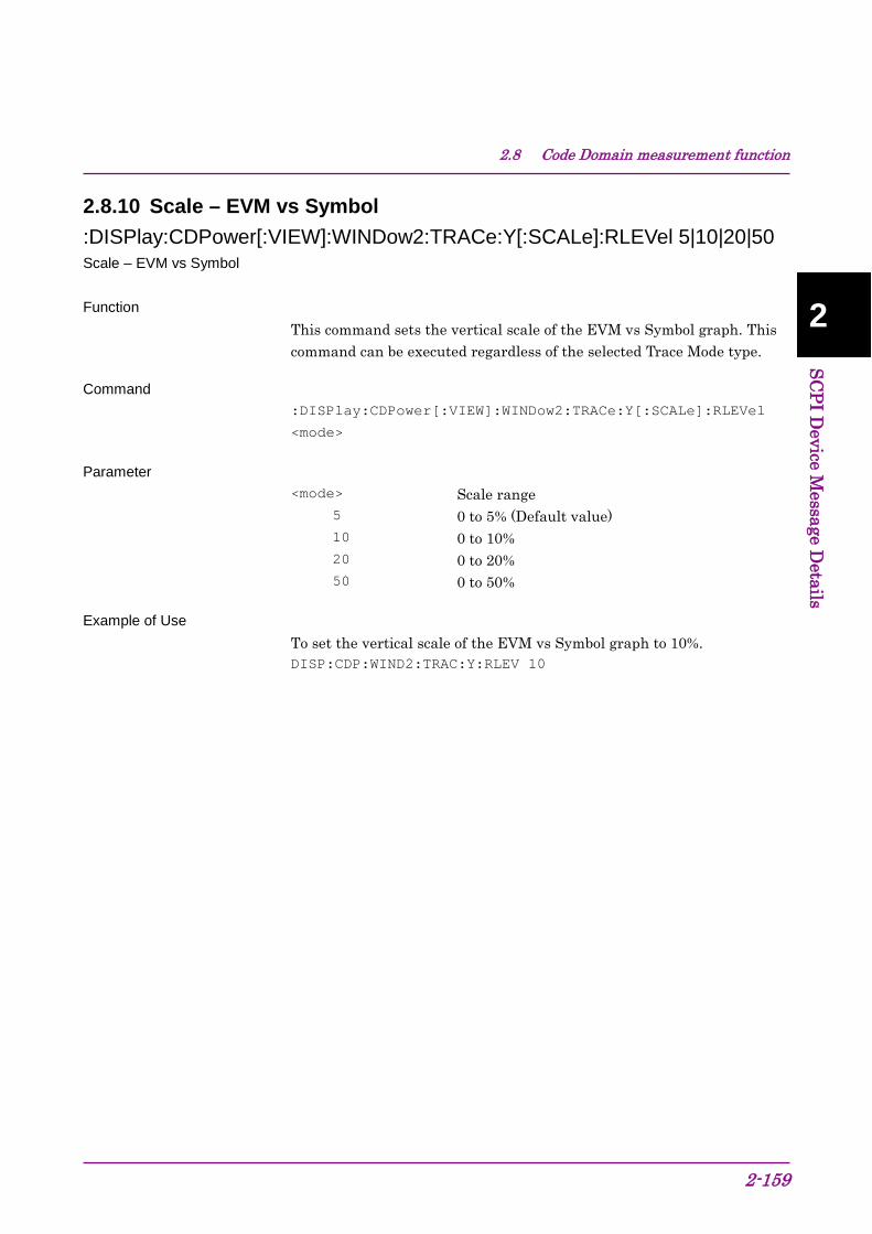
2.8 Code Domain measurement function
2-159
2
SCPI Device M
essage Details
2.8.10 Scale – EVM vs Symbol :DISPlay:CDPower[:VIEW]:WINDow2:TRACe:Y[:SCALe]:RLEVel 5|10|20|50 Scale – EVM vs Symbol Function
This command sets the vertical scale of the EVM vs Symbol graph. This command can be executed regardless of the selected Trace Mode type.
Command :DISPlay:CDPower[:VIEW]:WINDow2:TRACe:Y[:SCALe]:RLEVel
<mode>
Parameter <mode> Scale range
5 0 to 5% (Default value) 10 0 to 10% 20 0 to 20% 50 0 to 50%
Example of Use To set the vertical scale of the EVM vs Symbol graph to 10%. DISP:CDP:WIND2:TRAC:Y:RLEV 10

Chapter 2 SCPI Device Message Details
2-160
:DISPlay:CDPower[:VIEW]:WINDow2:TRACe:Y[:SCALe]:RLEVel? Scale – EVM vs Symbol Query Function
This command queries the setting of the vertical scale of the EVM vs Symbol graph. This query can be executed regardless of the selected Trace Mode type.
Query :DISPlay:CDPower[:VIEW]:WINDow2:TRACe:Y[:SCALe]:RLEVel?
Response <mode>
Parameter <mode> Scale range
5 0 to 5% 10 0 to 10% 20 0 to 20% 50 0 to 50%
Example of Use To query the setting of the vertical scale of the EVM vs Symbol graph. DISP:CDP:WIND2:TRAC:Y:RLEV?
> 10

2.8 Code Domain measurement function
2-161
2
SCPI Device M
essage Details
2.8.11 Scale – Magnitude Error vs Symbol :DISPlay:CDPower[:VIEW]:WINDow3:TRACe:Y[:SCALe]:RLEVel 5|10|20|50 Scale – Magnitude Error vs Symbol Function
This command sets the vertical scale of the Magnitude Error vs Symbol graph. This command can be executed regardless of the selected Trace Mode type.
Command :DISPlay:CDPower[:VIEW]:WINDow3:TRACe:Y[:SCALe]:RLEVel
<mode>
Parameter <mode> Scale range
5 –5 to 5% (Default value) 10 –10 to 10% 20 –20 to 20% 50 –50 to 50%
Example of Use To set the vertical scale of the Magnitude Error vs Symbol graph to 10%. DISP:CDP:WIND3:TRAC:Y:RLEV 10

Chapter 2 SCPI Device Message Details
2-162
:DISPlay:CDPower[:VIEW]:WINDow3:TRACe:Y[:SCALe]:RLEVel? Scale – Magnitude Error vs Symbol Query Function
This command queries the setting of the vertical scale of the Magnitude Error vs Symbol graph. This query can be executed regardless of the selected Trace Mode type.
Query :DISPlay:CDPower[:VIEW]:WINDow3:TRACe:Y[:SCALe]:RLEVel?
Response <mode>
Parameter <mode> Scale range
5 –5 to 5% 10 –10 to 10% 20 –20 to 20% 50 –50 to 50%
Example of Use To query the setting of the vertical scale of the Magnitude Error vs Symbol graph. DISP:CDP:WIND3:TRAC:Y:RLEV?
> 10
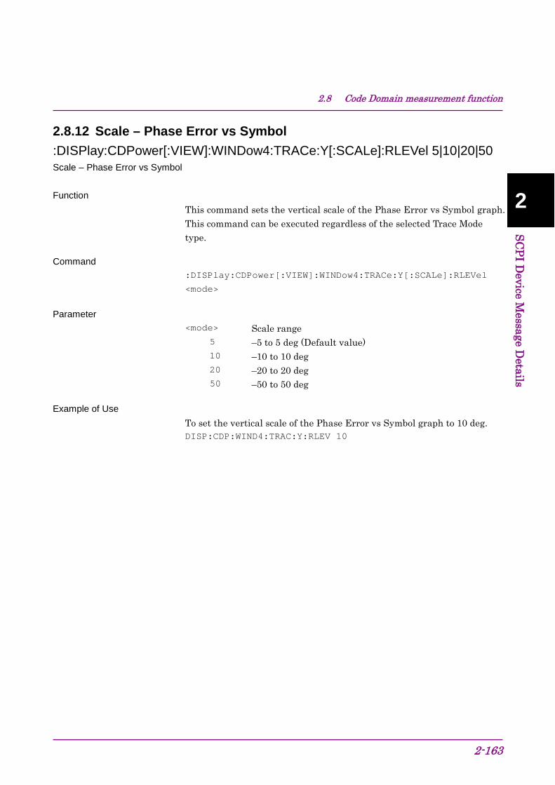
2.8 Code Domain measurement function
2-163
2
SCPI Device M
essage Details
2.8.12 Scale – Phase Error vs Symbol :DISPlay:CDPower[:VIEW]:WINDow4:TRACe:Y[:SCALe]:RLEVel 5|10|20|50 Scale – Phase Error vs Symbol Function
This command sets the vertical scale of the Phase Error vs Symbol graph. This command can be executed regardless of the selected Trace Mode type.
Command :DISPlay:CDPower[:VIEW]:WINDow4:TRACe:Y[:SCALe]:RLEVel
<mode>
Parameter <mode> Scale range
5 –5 to 5 deg (Default value) 10 –10 to 10 deg 20 –20 to 20 deg 50 –50 to 50 deg
Example of Use To set the vertical scale of the Phase Error vs Symbol graph to 10 deg. DISP:CDP:WIND4:TRAC:Y:RLEV 10
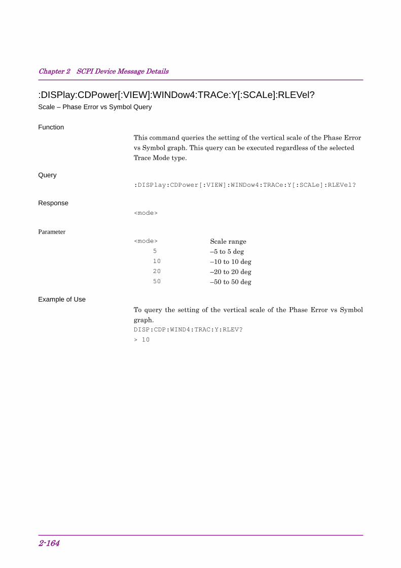
Chapter 2 SCPI Device Message Details
2-164
:DISPlay:CDPower[:VIEW]:WINDow4:TRACe:Y[:SCALe]:RLEVel? Scale – Phase Error vs Symbol Query Function
This command queries the setting of the vertical scale of the Phase Error vs Symbol graph. This query can be executed regardless of the selected Trace Mode type.
Query :DISPlay:CDPower[:VIEW]:WINDow4:TRACe:Y[:SCALe]:RLEVel?
Response <mode>
Parameter <mode> Scale range
5 –5 to 5 deg 10 –10 to 10 deg 20 –20 to 20 deg 50 –50 to 50 deg
Example of Use To query the setting of the vertical scale of the Phase Error vs Symbol graph. DISP:CDP:WIND4:TRAC:Y:RLEV?
> 10
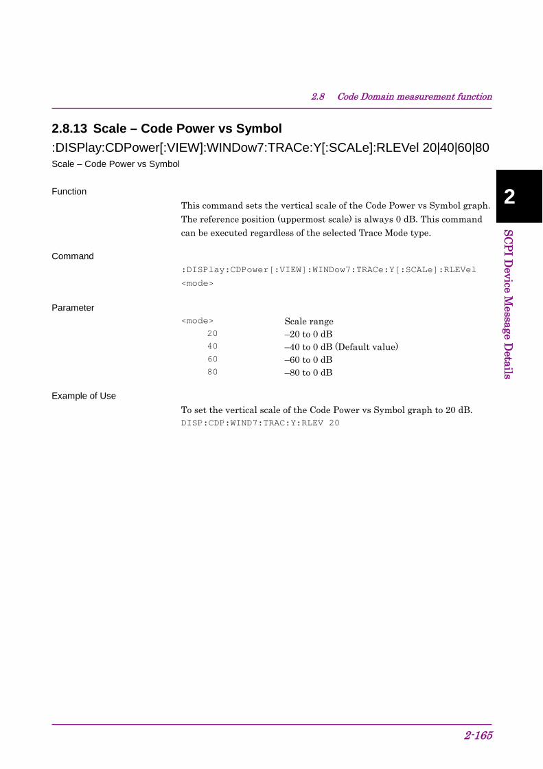
2.8 Code Domain measurement function
2-165
2
SCPI Device M
essage Details
2.8.13 Scale – Code Power vs Symbol :DISPlay:CDPower[:VIEW]:WINDow7:TRACe:Y[:SCALe]:RLEVel 20|40|60|80 Scale – Code Power vs Symbol Function
This command sets the vertical scale of the Code Power vs Symbol graph. The reference position (uppermost scale) is always 0 dB. This command can be executed regardless of the selected Trace Mode type.
Command :DISPlay:CDPower[:VIEW]:WINDow7:TRACe:Y[:SCALe]:RLEVel
<mode>
Parameter <mode> Scale range
20 –20 to 0 dB 40 –40 to 0 dB (Default value) 60 –60 to 0 dB 80 –80 to 0 dB
Example of Use To set the vertical scale of the Code Power vs Symbol graph to 20 dB. DISP:CDP:WIND7:TRAC:Y:RLEV 20

Chapter 2 SCPI Device Message Details
2-166
:DISPlay:CDPower[:VIEW]:WINDow7:TRACe:Y[:SCALe]:RLEVel? Scale – Code Power vs Symbol Query Function
This command queries the setting of the vertical scale of the Code Power vs Symbol graph. The reference position (uppermost scale) is always 0 dB. This query can be executed regardless of the selected Trace Mode type.
Query :DISPlay:CDPower[:VIEW]:WINDow7:TRACe:Y[:SCALe]:RLEVel?
Response <mode>
Parameter <mode> Scale range
20 –20 to 0 dB 40 –40 to 0 dB 60 –60 to 0 dB 80 –80 to 0 dB
Example of Use To query the setting of the vertical scale of the Code Power vs Symbol graph. DISP:CDP:WIND7:TRAC:Y:RLEV?
> 20

2.8 Code Domain measurement function
2-167
2
SCPI Device M
essage Details
2.8.14 Marker – On/Off :CALCulate:CDPower:MARKer[:STATe] OFF|ON|0|1 Marker – On/Off Function
This command sets the marker display On/Off when Code Domain measurement is selected.
Command :CALCulate:CDPower:MARKer[:STATe] <switch>
Parameter <switch> Marker
0|OFF Off 1|ON On (Default value)
Example of Use To display the marker. CALC:CDP:MARK 1
:CALCulate:CDPower:MARKer[:STATe]? Marker – On/Off Query Function
This command queries the marker display On/Off when Code Domain measurement is selected.
Query :CALCulate:CDPower:MARKer[:STATe]?
Response <switch>
Parameter <switch> Marker
0 Off 1 On
Example of Use To query the setting of Marker. CALC:CDP:MARK?
> 1

Chapter 2 SCPI Device Message Details
2-168
2.8.15 Marker Number :CALCulate:CDPower:MARKer:SYMBol <integer> Marker Number Function
This command sets in symbol units the marker position of the Constellation, EVM, Magnitude Error, Phase Error, and Code Power graphs. The setting range differs depending on the measurement result.
Command :CALCulate:CDPower:MARKer:SYMBol <integer>
Parameter <integer> Marker Number
Range 0 to (2560/SF) –1 Resolution 1 Default value 0
Example of Use To set the marker position to the 10th symbol. CALC:CDP:MARK:SYMB 10
:CALCulate:CDPower:MARKer:SYMBol? Marker Number Query Function
This command queries in symbol units the marker position of the Constellation, EVM, Magnitude Error, Phase Error, and Code Power graphs.
Query :CALCulate:CDPower:MARKer:SYMBol?
Response <integer>
Parameter <integer> Marker Number
Range 0 to (2560/SF) –1 Resolution 1
Example of Use To query the marker position. CALC:CDP:MARK:SYMB?
> 10

2.8 Code Domain measurement function
2-169
2
SCPI Device M
essage Details
2.8.16 Marker Value :CALCulate:CDPower:MARKer:X? Marker X Axis Value for Constellation – Query Function
This command queries the I-phase value at the marker position when the Constellation is displayed in the bottom graph window.
Query :CALCulate:CDPower:MARKer:X?
Response <real>
Parameter <real> I-phase at marker position in Constellation
Example of Use To query the I-phase value at the marker position in the Constellation. CALC:CDP:MARK:X?
> 1.0014
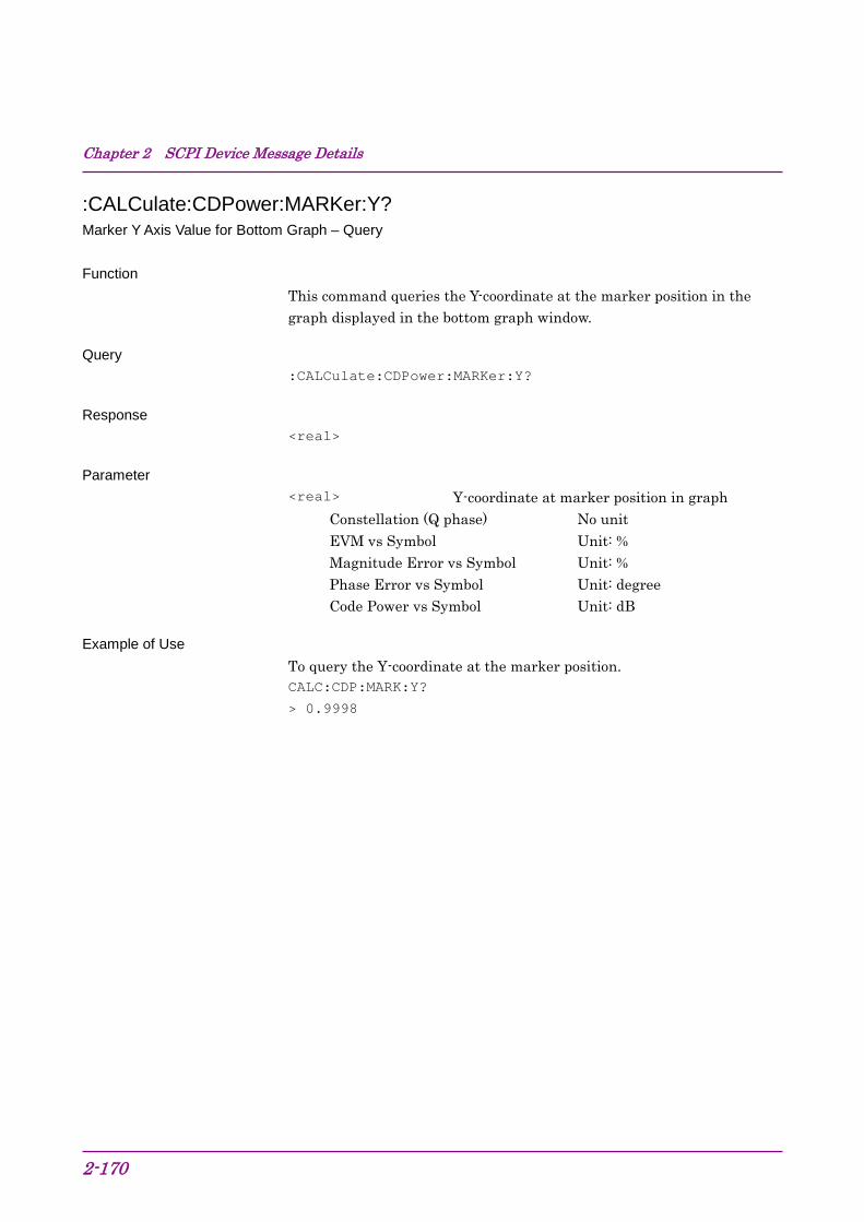
Chapter 2 SCPI Device Message Details
2-170
:CALCulate:CDPower:MARKer:Y? Marker Y Axis Value for Bottom Graph – Query Function
This command queries the Y-coordinate at the marker position in the graph displayed in the bottom graph window.
Query :CALCulate:CDPower:MARKer:Y?
Response <real>
Parameter <real> Y-coordinate at marker position in graph
Constellation (Q phase) No unit EVM vs Symbol Unit: % Magnitude Error vs Symbol Unit: % Phase Error vs Symbol Unit: degree Code Power vs Symbol Unit: dB
Example of Use To query the Y-coordinate at the marker position. CALC:CDP:MARK:Y?
> 0.9998

2.8 Code Domain measurement function
2-171
2
SCPI Device M
essage Details
:CALCulate:CDPower:MARKer:Y:CDOMain? Marker Y axis Value for Code Domain Trace – Query Function
This command queries the Y-coordinate at the marker position in the selected Code Domain Trace (Code Domain Power or Code Domain Error).
Query :CALCulate:CDPower:MARKer:Y:CDOMain?
Response <real>
Parameter <real> Y-coordinate at marker position in graph
Unit dB
Example of Use To query the Y-coordinate at the marker position. CALC:CDP:MARK:Y:CDOM?
> –10.12
:CALCulate:CDPower:MARKer:Y:CDOMain:CPOWer? Marker Y axis value for Code Domain Power – Query Function
This command queries the Code Power at the marker position in the Code Domain Power graph.
Query :CALCulate:CDPower:MARKer:Y:CDOMain:CPOWer?
Response <1>
Parameter <real> Code Power at marker position in graph
Unit dB
Example of Use To query the Code Power at the marker position. CALC:CDP:MARK:Y:CDOM:CPOW?
> –10.12

Chapter 2 SCPI Device Message Details
2-172
:CALCulate:CDPower:MARKer:Y:CDOMain:CERRor? Marker Y axis value for Code Domain Error – Query Function
This command queries the Code Error at the marker position in the Code Domain Error graph.
Query :CALCulate:CDPower:MARKer:Y:CDOMain:CERRor?
Response <real>
Parameter <real> Code Error at marker position in graph
Unit dB
Example of Use To query the Code Error at the marker position. CALC:CDP:MARK:Y:CDOM:CERR?
> –50.12
:CALCulate:CDPower:MARKer:Y:CDOMain:SFACtor? Spreading Factor Value for Code Domain Graph – Query Function
This command queries the Spreading Factor at the marker in the Code Domain Trace.
Query :CALCulate:CDPower:MARKer:Y:CDOMain:SFACtor?
Response <integer>
Parameter <integer> Spreading Factor at marker position in graph
Example of Use
To query the Spreading Factor at the marker position. CALC:CDP:MARK:Y:CDOM:SFAC?
> 64

2.8 Code Domain measurement function
2-173
2
SCPI Device M
essage Details
:CALCulate:CDPower:MARKer:Y:CDOMain:CCODe? Channelization Code Number for Code Domain Trace – Query Function
This command queries the Channelization Code Number at the marker position in the Code Domain Trace.
Query :CALCulate:CDPower:MARKer:Y:CDOMain:CCODe?
Response <integer>
Parameter <integer> Channelization Code Number at marker position
in graph Example of Use
To query the Channelization Code Number at the marker position. CALC:CDP:MARK:Y:CDOM:CCOD?
> 16
:CALCulate:CDPower:MARKer:Y:CDOMain:MODulation? Modulataion for Code Domain Trace – Query Function
This command queries the Modulation at the marker position in the Code Domain Trace.
Query :CALCulate:CDPower:MARKer:Y:CDOMain:MODulation?
Response <mode>
Parameter <mode> Modulation at marker position in graph
QPSK QPSK 16Q 16QAM 64Q 64QAM NONE None (inactive)
Example of Use To query the Modulation at the marker position. CALC:CDP:MARK:Y:CDOM:MOD?
> QPSK
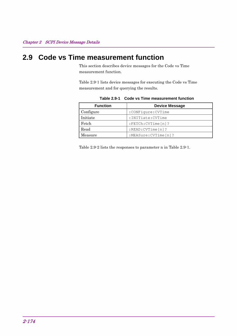
Chapter 2 SCPI Device Message Details
2-174
2.9 Code vs Time measurement function This section describes device messages for the Code vs Time measurement function.
Table 2.9-1 lists device messages for executing the Code vs Time measurement and for querying the results.
Table 2.9-1 Code vs Time measurement function
Function Device Message Configure :CONFigure:CVTime
Initiate :INITiate:CVTime
Fetch :FETCh:CVTime[n]?
Read :READ:CVTime[n]?
Measure :MEASure:CVTime[n]?
Table 2.9-2 lists the responses to parameter n in Table 2.9-1.

2.9 Code vs Time measurement function
2-175
2
SCPI Device M
essage Details
Table 2.9-2 Responses to Code vs Time Measurement Results
n Result Mode Response
1 or omitted
A
Returns the values below for the selected code and slot in comma-separated value format, in the following order. 1. EVM(RMS) [%] 2. EVM(Peak) [%] 3. Magnitude Error [%] 4. Phase Error [%] 5. Code Power [dB] 6. Number of detected SF 7. Number of code number for detected SF 8. Modulation type for detected SF QPSK QPSK 16Q 16QAM 64Q 64QAM NONE Inactive channel 9. Mean Power [dBm] 10. P−CPICH Power [dB] 11. P−SCH Power [dB] 12. S−SCH Power [dB] 13. Total Active Power [dB]
B
Returns the values below for the selected code and slot in comma-separated value format, in the following order. 1. EVM(RMS) [%] 2. EVM(Peak) [%] 3. Magnitude Error [%] 4. Phase Error [%] 5. Mean Power [dBm] 6. Code Power [dB] 7. to 10. –999.0 11. Total Active Power [dB] 12. P−CPICH Power [dB] 13. to 27. –999.0 28. P−SCH Power [dB] 29. S−SCH Power [dB] 30. to 44. –999.0
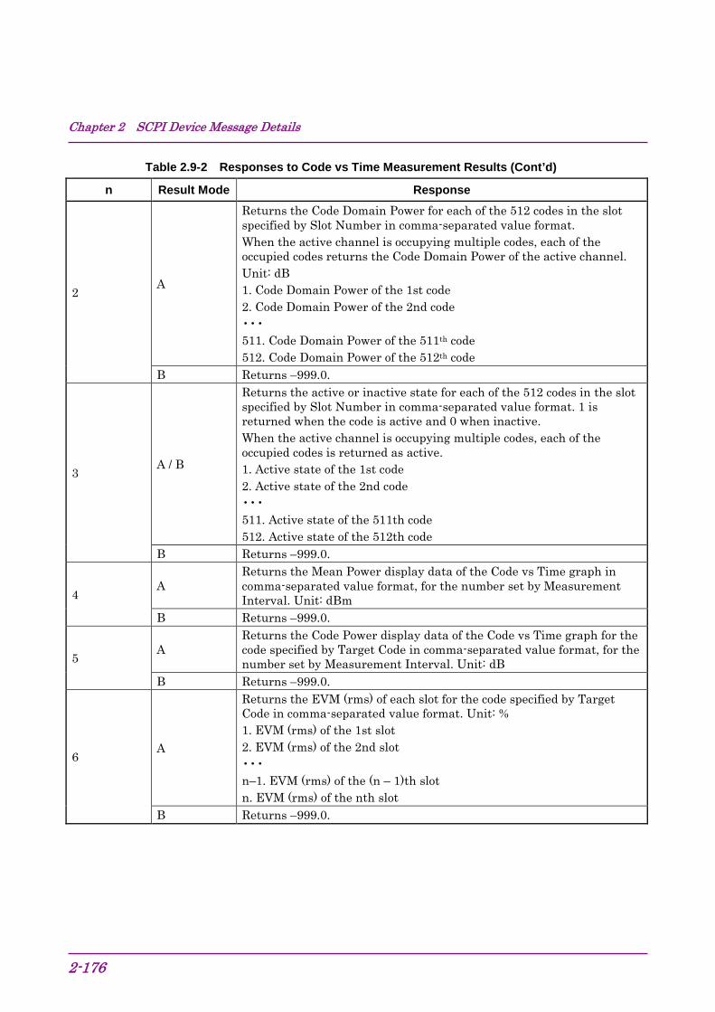
Chapter 2 SCPI Device Message Details
2-176
Table 2.9-2 Responses to Code vs Time Measurement Results (Cont’d)
n Result Mode Response
2 A
Returns the Code Domain Power for each of the 512 codes in the slot specified by Slot Number in comma-separated value format. When the active channel is occupying multiple codes, each of the occupied codes returns the Code Domain Power of the active channel. Unit: dB 1. Code Domain Power of the 1st code 2. Code Domain Power of the 2nd code ••• 511. Code Domain Power of the 511th code 512. Code Domain Power of the 512th code
B Returns –999.0.
3 A / B
Returns the active or inactive state for each of the 512 codes in the slot specified by Slot Number in comma-separated value format. 1 is returned when the code is active and 0 when inactive. When the active channel is occupying multiple codes, each of the occupied codes is returned as active. 1. Active state of the 1st code 2. Active state of the 2nd code ••• 511. Active state of the 511th code 512. Active state of the 512th code
B Returns –999.0.
4 A
Returns the Mean Power display data of the Code vs Time graph in comma-separated value format, for the number set by Measurement Interval. Unit: dBm
B Returns –999.0.
5 A
Returns the Code Power display data of the Code vs Time graph for the code specified by Target Code in comma-separated value format, for the number set by Measurement Interval. Unit: dB
B Returns –999.0.
6 A
Returns the EVM (rms) of each slot for the code specified by Target Code in comma-separated value format. Unit: % 1. EVM (rms) of the 1st slot 2. EVM (rms) of the 2nd slot ••• n–1. EVM (rms) of the (n – 1)th slot n. EVM (rms) of the nth slot
B Returns –999.0.

2.9 Code vs Time measurement function
2-177
2
SCPI Device M
essage Details
Table 2.9-2 Responses to Code vs Time Measurement Results (Cont’d)
n Result Mode Response
7 A
Returns the Spreading Factor of each slot for the code specified by Target Code in comma-separated value format. n is the setting value of Measurement Interval. Unit: None 1. Spreading Factor of the 1st slot 2. Spreading Factor of the 2nd slot ••• n–1. Spreading Factor of the (n – 1)th slot n. Spreading Factor of the nth slot
B Returns –999.0.
8 A
Returns the Channelization Code Number of each slot for the code specified by Target Code in comma-separated value format. n is the setting value of Measurement Interval. Unit: None 1. Channelization Code Number of the 1st slot 2. Channelization Code Number of the 2nd slot ••• n–1. Channelization Code Number of the (n – 1)th slot n. Channelization Code Number of the nth slot
B Returns –999.0.
9 A
Returns the modulation method of each slot for the code specified by Target Code in comma-separated value format. n is the setting value of Measurement Interval. The relationships between the responses and the modulation methods are as follows. QPSK QPSK 16Q 16QAM 64Q 64QAM NONE Inactive channel 1. Modulation method of the 1st slot 2. Modulation method of the 2nd slot ••• n–1. Modulation method of the (n – 1)th slot n. Modulation method of the nth slot
B Returns –999.0.
13 A
Returns the Code Domain Error for each of the 512 codes in the slot specified by Slot Number in comma-separated value format. Unit: dB When the active channel is occupying multiple codes, each of the occupied codes returns the Code Domain Error of the active channel. 1. Code Domain Power of the 1st code 2. Code Domain Power of the 2nd code ••• 511. Code Domain Power of the 511th code 512. Code Domain Power of the 512th code
B Returns –999.0.
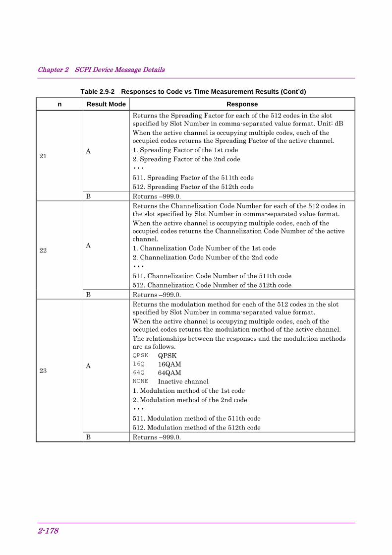
Chapter 2 SCPI Device Message Details
2-178
Table 2.9-2 Responses to Code vs Time Measurement Results (Cont’d)
n Result Mode Response
21 A
Returns the Spreading Factor for each of the 512 codes in the slot specified by Slot Number in comma-separated value format. Unit: dB When the active channel is occupying multiple codes, each of the occupied codes returns the Spreading Factor of the active channel. 1. Spreading Factor of the 1st code 2. Spreading Factor of the 2nd code ••• 511. Spreading Factor of the 511th code 512. Spreading Factor of the 512th code
B Returns –999.0.
22 A
Returns the Channelization Code Number for each of the 512 codes in the slot specified by Slot Number in comma-separated value format. When the active channel is occupying multiple codes, each of the occupied codes returns the Channelization Code Number of the active channel. 1. Channelization Code Number of the 1st code 2. Channelization Code Number of the 2nd code ••• 511. Channelization Code Number of the 511th code 512. Channelization Code Number of the 512th code
B Returns –999.0.
23 A
Returns the modulation method for each of the 512 codes in the slot specified by Slot Number in comma-separated value format. When the active channel is occupying multiple codes, each of the occupied codes returns the modulation method of the active channel. The relationships between the responses and the modulation methods are as follows. QPSK QPSK 16Q 16QAM 64Q 64QAM NONE Inactive channel 1. Modulation method of the 1st code 2. Modulation method of the 2nd code ••• 511. Modulation method of the 511th code 512. Modulation method of the 512th code
B Returns –999.0.
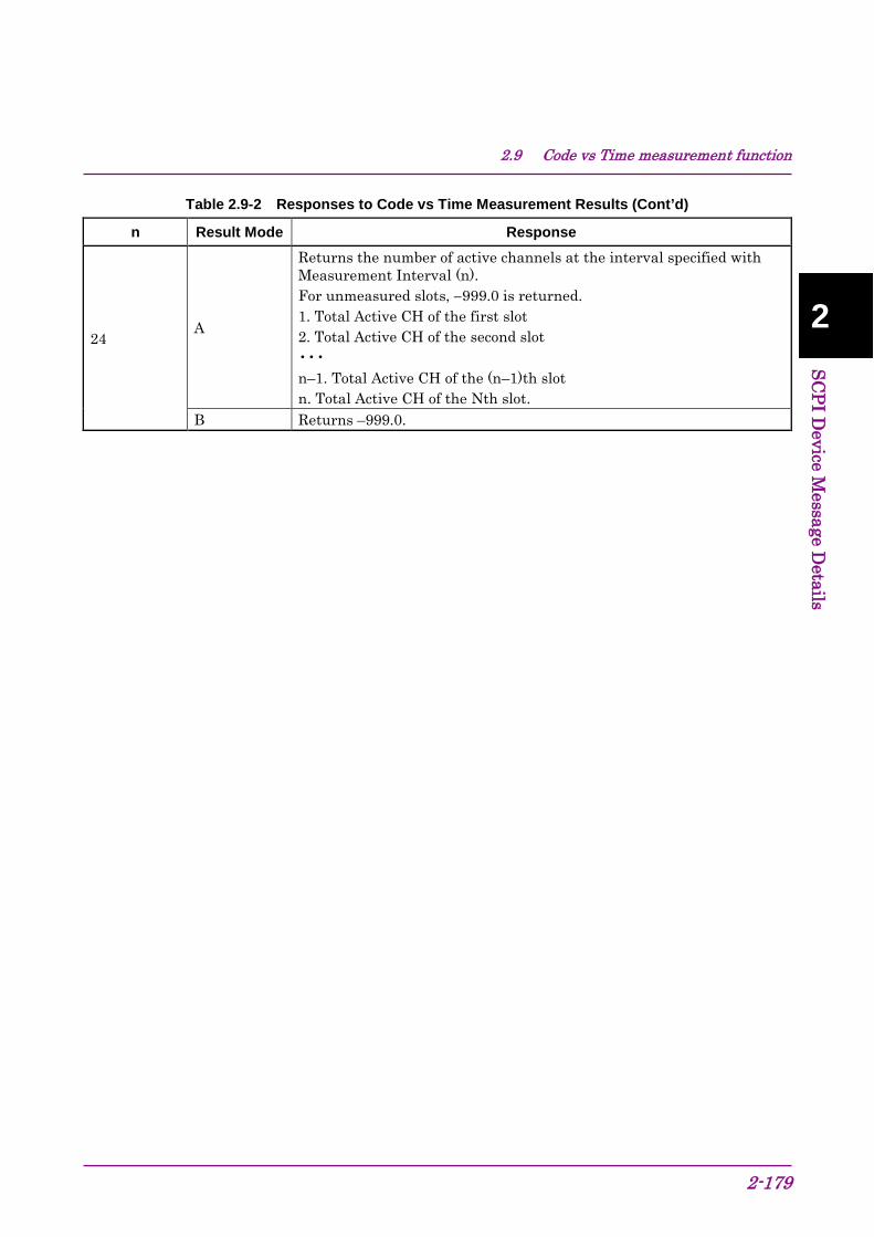
2.9 Code vs Time measurement function
2-179
2
SCPI Device M
essage Details
Table 2.9-2 Responses to Code vs Time Measurement Results (Cont’d)
n Result Mode Response
24 A
Returns the number of active channels at the interval specified with Measurement Interval (n). For unmeasured slots, −999.0 is returned. 1. Total Active CH of the first slot 2. Total Active CH of the second slot ••• n–1. Total Active CH of the (n–1)th slot n. Total Active CH of the Nth slot.
B Returns –999.0.
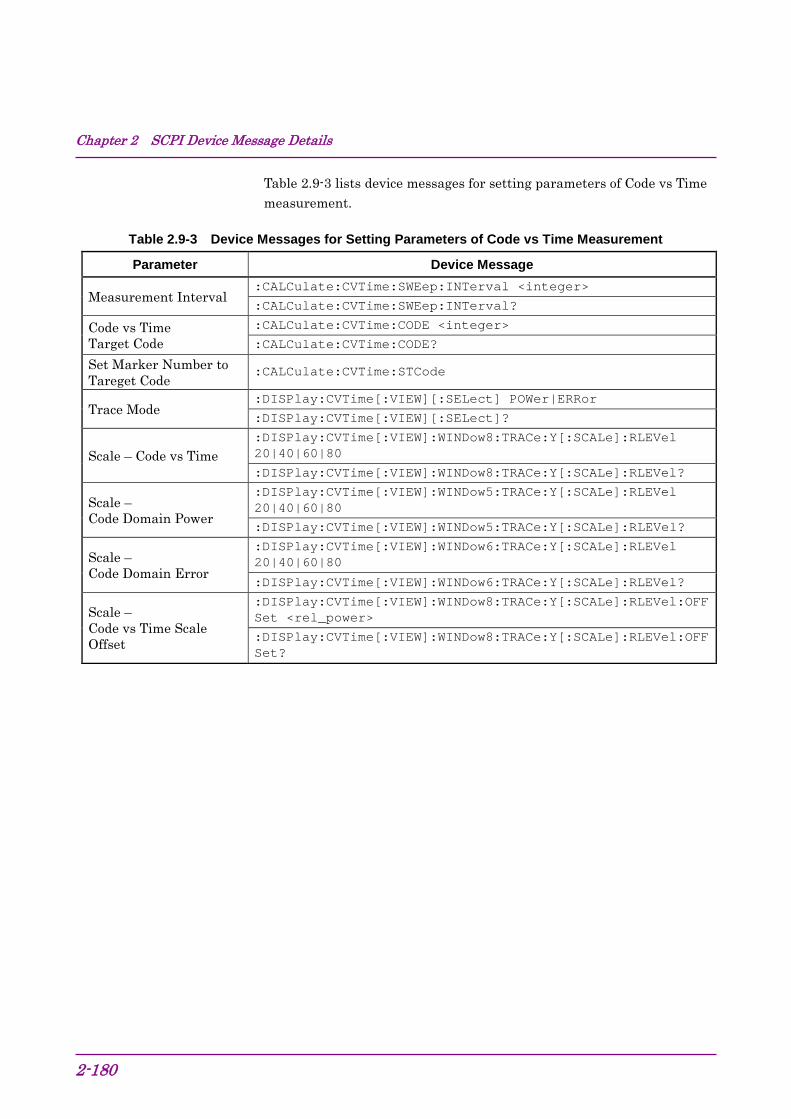
Chapter 2 SCPI Device Message Details
2-180
Table 2.9-3 lists device messages for setting parameters of Code vs Time measurement.
Table 2.9-3 Device Messages for Setting Parameters of Code vs Time Measurement
Parameter Device Message
Measurement Interval :CALCulate:CVTime:SWEep:INTerval <integer>
:CALCulate:CVTime:SWEep:INTerval?
Code vs Time Target Code
:CALCulate:CVTime:CODE <integer>
:CALCulate:CVTime:CODE?
Set Marker Number to Tareget Code
:CALCulate:CVTime:STCode
Trace Mode :DISPlay:CVTime[:VIEW][:SELect] POWer|ERRor
:DISPlay:CVTime[:VIEW][:SELect]?
Scale – Code vs Time :DISPlay:CVTime[:VIEW]:WINDow8:TRACe:Y[:SCALe]:RLEVel 20|40|60|80
:DISPlay:CVTime[:VIEW]:WINDow8:TRACe:Y[:SCALe]:RLEVel?
Scale – Code Domain Power
:DISPlay:CVTime[:VIEW]:WINDow5:TRACe:Y[:SCALe]:RLEVel 20|40|60|80
:DISPlay:CVTime[:VIEW]:WINDow5:TRACe:Y[:SCALe]:RLEVel?
Scale – Code Domain Error
:DISPlay:CVTime[:VIEW]:WINDow6:TRACe:Y[:SCALe]:RLEVel 20|40|60|80
:DISPlay:CVTime[:VIEW]:WINDow6:TRACe:Y[:SCALe]:RLEVel?
Scale – Code vs Time Scale Offset
:DISPlay:CVTime[:VIEW]:WINDow8:TRACe:Y[:SCALe]:RLEVel:OFFSet <rel_power>
:DISPlay:CVTime[:VIEW]:WINDow8:TRACe:Y[:SCALe]:RLEVel:OFFSet?

2.9 Code vs Time measurement function
2-181
2
SCPI Device M
essage Details
Table 2.9-4 lists device messages for setting the marker and querying the value at the marker position during Code vs Time measurement.
Table 2.9-4 Setting Marker for Code vs Time Measurement
Parameter Device Message
Marker – On/Off :CALCulate:CVTime:MARKer[:STATe] OFF|ON|0|1
:CALCulate:CVTime:MARKer[:STATe]?
Active Trace :CALCulate:CVTime:MARKer:ACTive CVTime|BOTTom
:CALCulate:CVTime:MARKer:ACTive?
Code vs Time Slot Number
:CALCulate:CVTime:SLOT <integer>
:CALCulate:CVTime:SLOT?
Marker Y axis - Mean Power Value for Code vs Time Graph
:CALCulate:CVTime:MARKer:Y:CVTime:MPOWer?
Marker Y axis - Code Power Value for Code vs Time Graph
:CALCulate:CVTime:MARKer:Y:CVTime:CPOWer?
Marker Y axis - Spreading Factor for Code vs Time Graph
:CALCulate:CVTime:MARKer:Y:CVTime:SFACtor?
Marker Y axis - Channelization Code Number for Code vs Time Graph
:CALCulate:CVTime:MARKer:Y:CVTime:CCODe?
Marker Y axis - Modulation for Code vs Time Graph
:CALCulate:CVTime:MARKer:Y:CVTime:MODulation?
Bottom Graph Marker Number
:CALCulate:CVTime:MARKer:MNUMber <integer>
:CALCulate:CVTime:MARKer:MNUMber?
Marker Y axis Value for Code Domain Graph
:CALCulate:CVTime:MARKer:Y:CDOMain?
Marker Y axis Code Power for Code Domain Power
:CALCulate:CVTime:MARKer:Y:CDOMain:CPOWer?
Marker Y axis Code Error for Code Domain Error
:CALCulate:CVTime:MARKer:Y:CDOMain:CERRor?
Marker Y axis Spreading Factor for Code Domain Graph
:CALCulate:CVTime:MARKer:Y:CDOMain:SFACtor?
Marker Y axis Channelization Code for Code Domain Graph
:CALCulate:CVTime:MARKer:Y:CDOMain:CCODe?
Marker Y axis Modulation for Code Domain Graph
:CALCulate:CVTime:MARKer:Y:CDOMain:MODulation?
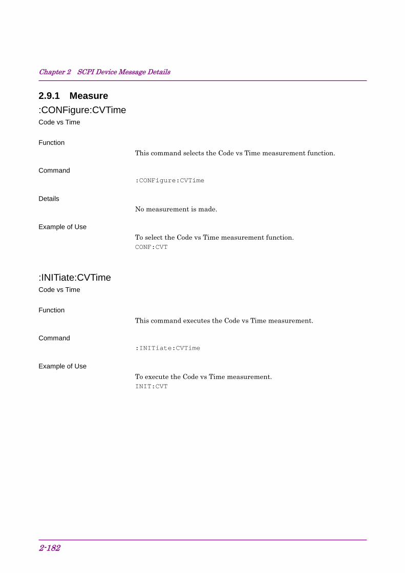
Chapter 2 SCPI Device Message Details
2-182
2.9.1 Measure :CONFigure:CVTime Code vs Time Function
This command selects the Code vs Time measurement function.
Command :CONFigure:CVTime
Details No measurement is made.
Example of Use To select the Code vs Time measurement function. CONF:CVT
:INITiate:CVTime Code vs Time Function
This command executes the Code vs Time measurement.
Command :INITiate:CVTime
Example of Use To execute the Code vs Time measurement. INIT:CVT

2.9 Code vs Time measurement function
2-183
2
SCPI Device M
essage Details
:FETCh:CVTime[n]? Code vs Time Query Function
This command queries the Code vs Time measurement results.
Query :FETCh:CVTime[n]?
Response Refer to Table 2.9-2.
Example of Use To query the Code vs Time measurement results. FETC:CVT?
:READ:CVTime[n]? Code vs Time Query Function
This command queries the results after executing single Code vs Time measurement with the current setting values.
Query :READ:CVTime[n]?
Response Refer to Table 2.9-2.
Example of Use To query the results of single Code vs Time measurement. READ:CVT?
Related Command This command has the same function as the following command. :MEASure:CVTime[n]?

Chapter 2 SCPI Device Message Details
2-184
:MEASure:CVTime[n]? Code vs Time Query Function
This command queries the results after executing single Code vs Time measurement with the current setting values.
Refer to :READ:CVTime[n]?
Related Command This command has the same function as the following command. :READ:CVTime[n]?
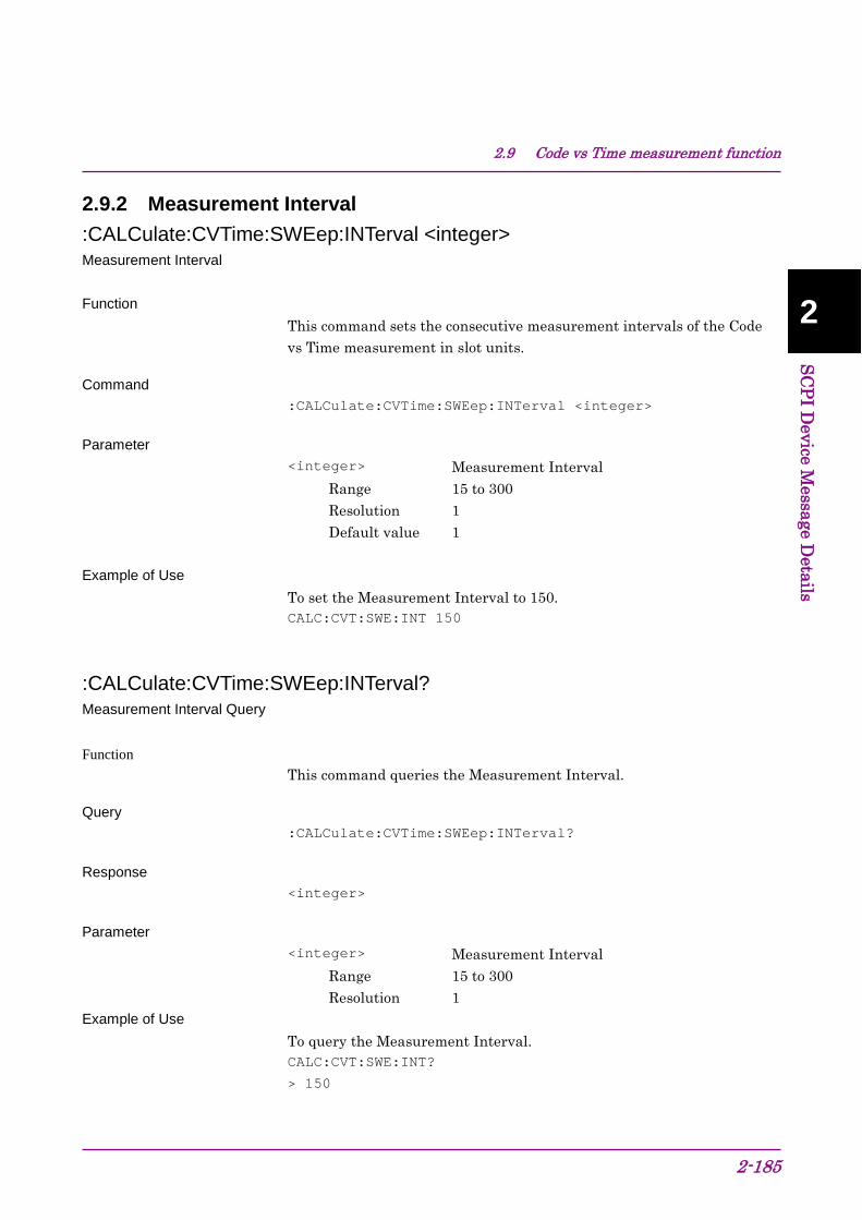
2.9 Code vs Time measurement function
2-185
2
SCPI Device M
essage Details
2.9.2 Measurement Interval :CALCulate:CVTime:SWEep:INTerval <integer> Measurement Interval Function
This command sets the consecutive measurement intervals of the Code vs Time measurement in slot units.
Command :CALCulate:CVTime:SWEep:INTerval <integer>
Parameter <integer> Measurement Interval
Range 15 to 300 Resolution 1 Default value 1
Example of Use
To set the Measurement Interval to 150. CALC:CVT:SWE:INT 150
:CALCulate:CVTime:SWEep:INTerval? Measurement Interval Query Function
This command queries the Measurement Interval.
Query :CALCulate:CVTime:SWEep:INTerval?
Response <integer>
Parameter <integer> Measurement Interval
Range 15 to 300 Resolution 1
Example of Use To query the Measurement Interval. CALC:CVT:SWE:INT?
> 150

Chapter 2 SCPI Device Message Details
2-186
2.9.3 Code vs Time Target Code :CALCulate:CVTime:CODE <integer> Code vs Time Target Code Function
This command sets the code number targeted for analysis and display.
Command :CALCulate:CVTime:CODE <integer>
Parameter <integer> Code vs Time Target Code
Range 0 to 511 Resolution 1 Default value 0
Example of Use To set the Code vs Time Target Code to 16. CALC:CVT:CODE 16
:CALCulate:CVTime:CODE? Code vs Time Target Code – Query Function
This command queries the code number targeted for analysis and display.
Command :CALCulate:CVTime:CODE?
Parameter <integer> Code vs Time Target Code
Range 0 to 511 Resolution 1
Example of Use
To query the setting of Code vs Time Target Code. CALC:CDP:CODE?
> 16
2.9 Code vs Time measurement function
2-187
2
SCPI Device M
essage Details
2.9.4 Set Marker Number to Target Code :CALCulate:CVTime:STCode Set Marker Number to Target Code Function
This command sets the marker value (code) in the bottom graph window (Code Domain graph) as the code number targeted for analysis and display.
Command :CALCulate:CVTime:STCode
Example of Use To set the marker value in the bottom graph window as the Code vs Time Target Code. CALC:CVT:STC

Chapter 2 SCPI Device Message Details
2-188
2.9.5 Trace Mode :DISPlay:CVTime[:VIEW][:SELect] CDPower|CDError Trace Mode Function
This command sets the type of the graph displayed in the bottom graph window when Code vs Time measurement is selected.
Command :DISPlay:CVTime[:VIEW][:SELect] <mode>
Parameter <mode> Trace Mode
POWer Code Domain Power ERRor Code Domain Error
Example of Use To set the Trace Mode to Code Domain Power. DISP:CVT POW
:DISPlay:CVTime[:VIEW][:SELect]? Trace Mode Query Function
This command queries the type of the graph displayed in the bottom graph window when Code vs Time measurement is selected.
Query :DISPlay:CVTime[:VIEW][:SELect]?
Response <mode>
Parameter <mode> Trace Mode
POW Code Domain Power ERR Code Domain Error
Example of Use To query the setting of Trace Mode. DISP:CVT?
> POW

2.9 Code vs Time measurement function
2-189
2
SCPI Device M
essage Details
2.9.6 Scale – Code vs Time :DISPlay:CVTime[:VIEW]:WINDow8:TRACe:Y[:SCALe]:RLEVel 20|40|60|80 Scale – Code vs Time Function
This command sets the vertical scale of the Code vs Time graph. This command can be executed regardless of the selected Trace Mode type.
Details The reference position is set as follows: Reference position dBm = Input Level dBm + Code vs Time Scale Offset dB + 10 dB (in 5 dB steps, rounding up fractions less than 5 dB)
Command :DISPlay:CVTime[:VIEW]:WINDow8:TRACe:Y[:SCALe]:RLEVel
<mode>
Parameter <mode> Scale range
20 Reference position –20 dB to reference position 40 Reference position –40 dB to reference position 60 Reference position –60 dB to reference position 80 Reference position –80 dB to reference position
(Default value)
Example of Use To set the vertical scale of the Code vs Time graph to 60 dB. DISP:CVT:WIND8:TRAC:Y:RLEV 60

Chapter 2 SCPI Device Message Details
2-190
:DISPlay:CVTime[:VIEW]:WINDow8:TRACe:Y[:SCALe]:RLEVel? Scale – Code vs Time Query Function
This command queries the setting of the vertical scale of the Code vs Time graph. This query can be executed regardless of the selected Trace Mode type.
Details The reference position is set as follows: Reference position dBm = Input Level dBm + Code vs Time Scale Offset dB + 10 dB (in 5 dB steps, rounding up fractions less than 5 dB)
Query :DISPlay:CVTime[:VIEW]:WINDow8:TRACe:Y[:SCALe]:RLEVel?
Response <mode>
Parameter <mode> Scale range
20 Reference position –20 dB to reference position 40 Reference position –40 dB to reference position 60 Reference position –60 dB to reference position 80 Reference position –80 dB to reference position
Example of Use To query the setting of the vertical scale of the Code vs Time graph. DISP:CVT:WIND8:TRAC:Y:RLEV?
> 60

2.9 Code vs Time measurement function
2-191
2
SCPI Device M
essage Details
2.9.7 Scale – Code Domain Power :DISPlay:CVTime[:VIEW]:WINDow5:TRACe:Y[:SCALe]:RLEVel 20|40|60|80 Scale – Code Domain Power Function
This command sets the vertical scale of the Code Domain Power graph. This command can be executed regardless of the selected Trace Mode type.
Command :DISPlay:CVTime[:VIEW]:WINDow5:TRACe:Y[:SCALe]:RLEVel
<mode>
Parameter <mode> Scale range
20 –20 to 0 dB 40 –40 to 0 dB 60 –60 to 0 dB 80 –80 to 0 dB (Default value)
Example of Use To set the vertical scale of the Code Domain Power graph to 60 dB. DISP:CVT:WIND5:TRAC:Y:RLEV 60
Chapter 2 SCPI Device Message Details
2-192
:DISPlay:CVTime[:VIEW]:WINDow5:TRACe:Y[:SCALe]:RLEVel? Scale – Code Domain Power Query Function
This command queries the setting of the vertical scale of the Code Domain Power graph. This query can be executed regardless of the selected Trace Mode type.
Query :DISPlay:CVTime[:VIEW]:WINDow5:TRACe:Y[:SCALe]:RLEVel?
Response <mode>
Parameter <mode> Scale range
20 –20 to 0 dB 40 –40 to 0 dB 60 –60 to 0 dB 80 –80 to 0 dB
Example of Use To query the setting of the vertical scale of the Code Domain Power graph. DISP:CVT:WIND5:TRAC:Y:RLEV?
> 60

2.9 Code vs Time measurement function
2-193
2
SCPI Device M
essage Details
2.9.8 Scale – Code Domain Error :DISPlay:CVTime[:VIEW]:WINDow6:TRACe:Y[:SCALe]:RLEVel 20|40|60|80 Scale – Code Domain Error Function
This command sets the vertical scale of the Code Domain Error graph. This command can be executed regardless of the selected Trace Mode type.
Command :DISPlay:CVTime[:VIEW]:WINDow6:TRACe:Y[:SCALe]:RLEVel
<mode>
Parameter <mode> Scale range
20 –80 to –60 dB 40 –80 to –40 dB 60 –80 to –20 dB 80 –80 to 0 dB (Default value)
Example of Use To set the vertical scale of the Code Domain Error graph to 20 dB. DISP:CVT:WIND6:TRAC:Y:RLEV 20

Chapter 2 SCPI Device Message Details
2-194
:DISPlay:CVTime[:VIEW]:WINDow6:TRACe:Y[:SCALe]:RLEVel? Scale – Code Domain Error Query Function
This command queries the setting of the vertical scale of the Code Domain Error graph. This query can be executed regardless of the selected Trace Mode type.
Query :DISPlay:CVTime[:VIEW]:WINDow6:TRACe:Y[:SCALe]:RLEVel?
Response <mode>
Parameter <mode> Scale range
20 –80 to –60 dB 40 –80 to –40 dB 60 –80 to –20 dB 80 –80 to 0 dB
Example of Use To query the setting of the vertical scale of the Code Domain Error graph. DISP:CDP:WIND6:TRAC:Y:RLEV?
> 20

2.9 Code vs Time measurement function
2-195
2
SCPI Device M
essage Details
2.9.9 Scale – Code vs Time Scale Offset :DISPlay:CVTime[:VIEW]:WINDow8:TRACe:Y[:SCALe]:RLEVel:OFFSet <rel_power> Scale – Code vs Time Scale Offset Function
This command sets the offset setting of the vertical scale of the Code vs Time graph. This command can be executed regardless of the selected Trace Mode type.
Details The reference position is set as follows: Reference position dBm = Input Level dBm + Code vs Time Scale Offset dB + 10 dB (in 5 dB steps, rounding up fractions less than 5 dB)
Command :DISPlay:CVTime[:VIEW]:WINDow8:TRACe:Y[:SCALe]:RLEVel:OF
FSet <rel_power>
Parameter < rel_power > Scale range offset value
Range –99.99 to 99.99 dB Resolution 0.01 dB Suffix code DB
dB is used when omitted. Default value 0.00 dB
Example of Use To set the vertical scale offset value of the Code vs Time graph to 10 dB. DISP:CVT:WIND8:TRAC:Y:RLEV:OFFS 10

Chapter 2 SCPI Device Message Details
2-196
:DISPlay:CVTime[:VIEW]:WINDow8:TRACe:Y[:SCALe]:RLEVel:OFFSet? Scale – Code vs Time Scale Offset Function
This command queries the offset setting of the vertical scale of the Code vs Time graph. This command can be executed regardless of the selected Trace Mode type.
Details The reference position is set as follows: Reference position dBm = Input Level dBm + Code vs Time Scale Offset dB + 10 dB (in 5 dB steps, rounding up fractions less than 5 dB)
Command :DISPlay:CVTime[:VIEW]:WINDow8:TRACe:Y[:SCALe]:RLEVel:OF
FSet?
Parameter < rel_power > Scale range offset value
Range –99.99 to 99.99 dB Resolution 0.01 dB
Example of Use To query the offset setting of the vertical scale of the Code vs Time graph. DISP:CVT:WIND8:TRAC:Y:RLEV:OFFS?
> 10.00

2.9 Code vs Time measurement function
2-197
2
SCPI Device M
essage Details
2.9.10 Marker – On/Off :CALCulate:CVTime:MARKer[:STATe] OFF|ON|0|1 Marker – On/Off Function
This command sets the marker display On/Off when Code vs Time measurement is selected.
Command :CALCulate:CVTime:MARKer[:STATe] <switch>
Parameter <switch> Marker
0|OFF Off 1|ON On (Default value)
Example of Use To display the marker. CALC:CDP:MARK 1
:CALCulate:CVTime:MARKer[:STATe]? Marker – On/Off Query Function
This command queries the marker display On/Off when Code vs Time measurement is selected.
Query :CALCulate:CVTime:MARKer[:STATe]?
Response <switch>
Parameter <switch> Marker
0 Off 1 On
Example of Use To query the setting of Marker. CALC:CVT:MARK?
> 1

Chapter 2 SCPI Device Message Details
2-198
2.9.11 Active Trace :CALCulate:CVTime:MARKer:ACTive CVTime|BOTTom Active Trace Function
This command sets the graph (position) of the marker setting target.
Command :CALCulate:CVTime:MARKer:ACTive CVTime|BOTTom
Parameter <switch> Marker Setting Target
CVTime Upper Graph Window BOTTom Bottom Graph window (Default value)
Example of Use
To set the marker setting target to the upper graph window. CALC:CVT:MARK:ACT CVT
:CALCulate:CVTime:MARKer:ACTive? Active Trace Query Function
This command queries the setting of Active Trace.
Query :CALCulate:CVTime:MARKer:ACTive?
Response <mode>
Parameter <mode> Active Trace
CVT Upper Graph window BOTT Bottom Graph window
Example of Use
To query the setting of Active Trace. CALC:CVT:MARK:ACT?
> CVT
2.9 Code vs Time measurement function
2-199
2
SCPI Device M
essage Details
2.9.12 Code vs Time Slot Number :CALCulate:CVTime:SLOT <integer> Code vs Time Slot Number Function
This command sets the marker position of the Code vs Time graph in slot units.
Command :CALCulate:CVTime:SLOT <integer>
Parameter <integer> Code vs Time Slot Number
Range 0 to Measurement Interval – 1 Resolution 1 Default value 0
Example of Use To set the marker position to the 10th slot. CALC:CVT:SLOT 10
:CALCulate:CVTime:SLOT? Code vs Time Slot Number Query Function
This command queries the marker position of the Code vs Time graph in slot units.
Query :CALCulate:CVTime:SLOT?
Response <integer>
Parameter <integer> Code vs Time Slot Number
Range 0 to MeasurementInterval – 1 Resolution 1
Example of Use To query the marker position. CALC:CVT:SLOT?
> 10

Chapter 2 SCPI Device Message Details
2-200
2.9.13 Marker Value :CALCulate:CVTime:MARKer:Y:CVTime:MPOWer? Marker Y axis - Mean Power Value for Code vs Time Graph – Query Function
This command queries the Mean Power at the marker position in the Code vs Time graph.
Query :CALCulate:CVTime:MARKer:Y:CVTime:MPOWer?
Response <real>
Parameter <real> Mean Power at marker position in graph
Unit dBm Example of Use
To query the Mean Power at the marker position. CALC:CVT:MARK:Y:CVT:MPOW?
> –10.51
:CALCulate:CVTime:MARKer:Y:CVTime:CPOWer? Marker Y axis - Code Power Value for Code vs Time Graph – Query Function
This command queries the Code Power at the marker position in the Code vs Time graph.
Query :CALCulate:CVTime:MARKer:Y:CVTime:CPOWer?
Response <real>
Parameter <real> Code Power at marker position in graph
Unit dB
Example of Use To query the Code Power at the marker position. CALC:CVT:MARK:Y:CVT:CPOW?
> –10.12

2.9 Code vs Time measurement function
2-201
2
SCPI Device M
essage Details
:CALCulate:CVTime:MARKer:Y:CVTime:SFACtor? Marker Y axis Spreading Factor for Code vs Time Graph – Query Function
This command queries the Spreading Factor at the marker position in the Code vs Time graph.
Query :CALCulate:CVTime:MARKer:Y:CVTime:SFACtor?
Response <integer>
Parameter <integer> Spreading Factor at marker position in graph
Example of Use To query the Spreading Factor at the marker position. CALC:CVT:MARK:Y:CVT:SFAC?
> 256
:CALCulate:CVTime:MARKer:Y:CVTime:CCODe? Marker Y axis Channelization Code Number for Code vs Time Graph – Query Function
This command queries the Channelization Code Number at the marker position in the Code vs Time graph.
Query :CALCulate:CVTime:MARKer:Y:CVTime:CCODe?
Response <integer>
Parameter <integer> Channelization Code Number at marker position
in graph Example of Use
To query the Channelization Code Number at the marker position. CALC:CVT:MARK:Y:CVT:CCOD?
> 16
Chapter 2 SCPI Device Message Details
2-202
:CALCulate:CVTime:MARKer:Y:CVTime:MODulation? Marker Y axis Modulataion for Code vs Time Graph – Query Function
This command queries the Modulation at the marker position in the Code vs Time graph.
Query :CALCulate:CVTime:MARKer:Y:CVTime:MODulation?
Response <mode>
Parameter <mode> Modulation at marker position in graph
QPSK QPSK 16Q 16QAM 64Q 64QAM NONE None (inactive)
Example of Use To query the Modulation at the marker position. CALC:CVT:MARK:Y:CVT:MOD?
> QPSK

2.9 Code vs Time measurement function
2-203
2
SCPI Device M
essage Details
2.9.14 Bottom Graph Marker Number :CALCulate:CVTime:MARKer:MNUMber <integer> Bottom Graph Marker Number Function
This command sets the marker position on the graph displayed in the bottom graph window.
Command :CALCulate:CVTime:MARKer:MNUMber <integer>
Parameter <integer> Bottom Graph Marker Number
Range 0 to 511 Resolution 1 Default value 0
Example of Use To set the marker position to 10. CALC:CVT:MARK:MNUM 10
:CALCulate:CVTime:MARKer:MNUMber? Bottom Graph Marker Number Query Function
This command queries the marker position on the graph displayed in the bottom graph window.
Query :CALCulate:CVTime:MARKer:MNUMber?
Response <integer>
Parameter <integer> Bottom Graph Marker Number
Range 0 to 511 Resolution 1
Example of Use To query the marker position. CALC:CVT:MARK:MNUM?
> 10

Chapter 2 SCPI Device Message Details
2-204
2.9.15 Marker Value :CALCulate:CVTime:MARKer:Y:CDOMain? Marker Y axis Value for Code Domain Graph – Query Function
This command queries the Y-coordinate at the marker position in the graph displayed in the bottom graph window.
Query :CALCulate:CVTime:MARKer:Y:CDOMain?
Response <real>
Parameter <real> Y-coordinate at marker position in graph
Unit dB Example of Use
To query the Y-coordinate at the marker position. CALC:CVT:MARK:Y:CDOM?
> –10.12
:CALCulate:CVTime:MARKer:Y:CDOMain:CPOWer? Marker Y axis Code Power for Code Domain Power – Query Function
This command queries the Code Power at the marker position in the Code Domain Power graph.
Query :CALCulate:CVTime:MARKer:Y:CDOMain:CPOWer?
Response <real>
Parameter <real> Code Power at marker position in graph
Unit dB
Example of Use To query the Code Power at the marker position. CALC:CVT:MARK:Y:CDOM:CPOW?
> –10.12

2.9 Code vs Time measurement function
2-205
2
SCPI Device M
essage Details
:CALCulate:CVTime:MARKer:Y:CDOMain:CERRor? Marker Y axis Code Error for Code Domain Error – Query Function
This command queries the Code Error at the marker position in the Code Domain Error graph.
Query :CALCulate:CVTime:MARKer:Y:CDOMain:CERRor?
Response <real>
Parameter <real> Code Error at marker position in graph
Unit dB
Example of Use To query the Code Error at the marker position. CALC:CVT:MARK:Y:CDOM:CERR?
> –50.12
:CALCulate:CVTime:MARKer:Y:CDOMain:SFACtor? Marker Y axis Spreading Factor for Code Domain Graph – Query Function
This command queries the Spreading Factor at the marker position on the graph displayed in the bottom graph window.
Query :CALCulate:CVTime:MARKer:Y:CDOMain:SFACtor?
Response <integer>
Parameter <integer> Spreading Factor at marker position in graph
Example of Use To query the Spreading Factor at the marker position. CALC:CVT:MARK:Y:CDOM:SFAC?
> 64
Chapter 2 SCPI Device Message Details
2-206
:CALCulate:CVTime:MARKer:Y:CDOMain:CCODe? Marker Y axis Channelization Code Number for Code Domain Graph – Query Function
This command queries the Channelization Code Number at the marker position on the graph displayed in the bottom graph window.
Query :CALCulate:CVTime:MARKer:Y:CDOMain:CCODe?
Response <integer>
Parameter <integer> Channelization Code Number at marker position
in graph
Example of Use To query the Channelization Code Number at the marker position. CALC:CVT:MARK:Y:CDOM:CCOD?
> 16

2.9 Code vs Time measurement function
2-207
2
SCPI Device M
essage Details
:CALCulate:CVTime:MARKer:Y:CDOMain:MODulation? Marker Y axis Modulataion for Code Domain Graph – Query Function
This command queries the Modulation at the marker position on the graph displayed in the bottom graph window.
Query :CALCulate:CVTime:MARKer:Y:CDOMain:MODulation?
Response <mode>
Parameter <mode> Modulation at marker position in graph
QPSK QPSK 16Q 16QAM 64Q 64QAM NONE None (inactive)
Example of Use To query the Modulation at the marker position. CALC:CVT:MARK:Y:CDOM:MOD?
> QPSK

Chapter 2 SCPI Device Message Details
2-208.

Chapter 3 SCPI Status Register
3-1
3
SCPI Status Register
This chapter describes the SCPI commands and the Status register for querying application statuses.
3.1 Querying Measurement Status ..................................... 3-2 3.2 STATus:QUEStionable Register................................... 3-3 3.3 STATus:OPERation Register ..................................... 3-15
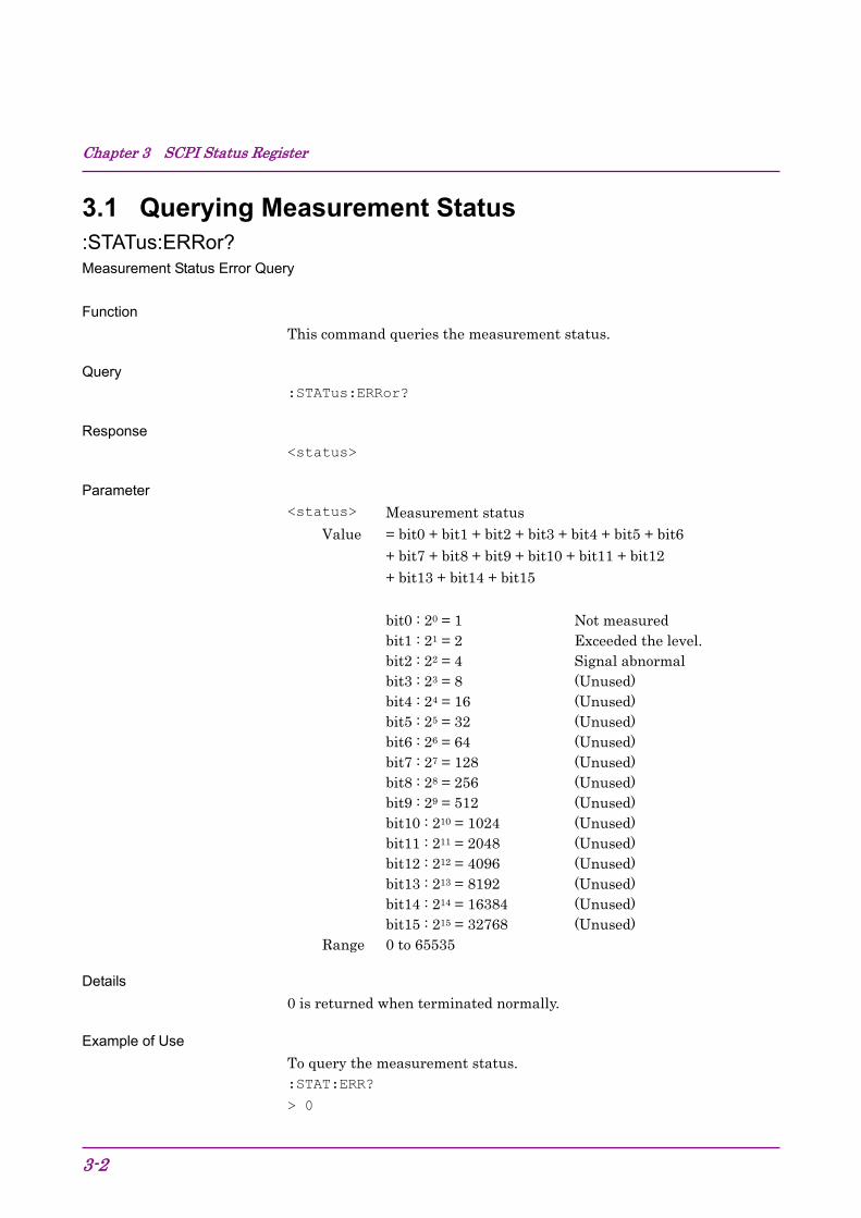
Chapter 3 SCPI Status Register
3-2
3.1 Querying Measurement Status :STATus:ERRor? Measurement Status Error Query
Function
This command queries the measurement status.
Query
:STATus:ERRor?
Response
<status>
Parameter
<status> Measurement status Value = bit0 + bit1 + bit2 + bit3 + bit4 + bit5 + bit6
+ bit7 + bit8 + bit9 + bit10 + bit11 + bit12 + bit13 + bit14 + bit15
bit0 : 20 = 1 Not measured bit1 : 21 = 2 Exceeded the level. bit2 : 22 = 4 Signal abnormal bit3 : 23 = 8 (Unused) bit4 : 24 = 16 (Unused) bit5 : 25 = 32 (Unused) bit6 : 26 = 64 (Unused) bit7 : 27 = 128 (Unused) bit8 : 28 = 256 (Unused) bit9 : 29 = 512 (Unused) bit10 : 210 = 1024 (Unused) bit11 : 211 = 2048 (Unused) bit12 : 212 = 4096 (Unused) bit13 : 213 = 8192 (Unused) bit14 : 214 = 16384 (Unused) bit15 : 215 = 32768 (Unused)
Range 0 to 65535
Details
0 is returned when terminated normally.
Example of Use
To query the measurement status. :STAT:ERR?
> 0

3.2 STATus:QUEStionable Register
3-3
3
SCPI Status Register
3.2 STATus:QUEStionable Register Figure 3.2-1, Table 3.2-1, Figure 3.2-2, and Table 3.2-2 show the layer structure of the QUEStionable Status register.
VOLTage (NOT USED) DB0 CURRent (NOT USED) DB1 TIME (NOT USED) DB2 POWer (NOT USED) DB3 TEMPerature (NOT USED) DB4 FREQuency DB5 PHASe (NOT USED) DB6 MODulation (NOT USED) DB7 CALibration (NOT USED) DB8 MEASure DB9 NOT USED DB10 NOT USED DB11 NOT USED DB12 INSTrument (NOT USED) DB13 Command Warning (NOT USED) DB14 NOT USED DB15
Status Byte Register DB3
Figure 3.2-1 QUEStionable Status Register
Table 3.2-1 Bit Definition of QUEStionable Status Register
Bit Definition DB5 Unlock Reference Clock DB9 QUEStionable Measure Register Summary
NOT USED DB0 NOT USED DB1 NOT USED DB2 NOT USED DB3 NOT USED DB4 Level Over DB5 NOT USED DB6 NOT USED DB7 Signal Abnormal DB8 NOT USED DB9 NOT USED DB10 NOT USED DB11 NOT USED DB12 NOT USED DB13 NOT USED DB14 NOT USED DB15
QUEStionable Status Register DB9
Figure 3.2-2 QUEStionable Measure Register
Table 3.2-2 Bit Definition of QUEStionable Measure Register
Bit Definition
DB5 Exceeded the level. DB8 Signal abnormal
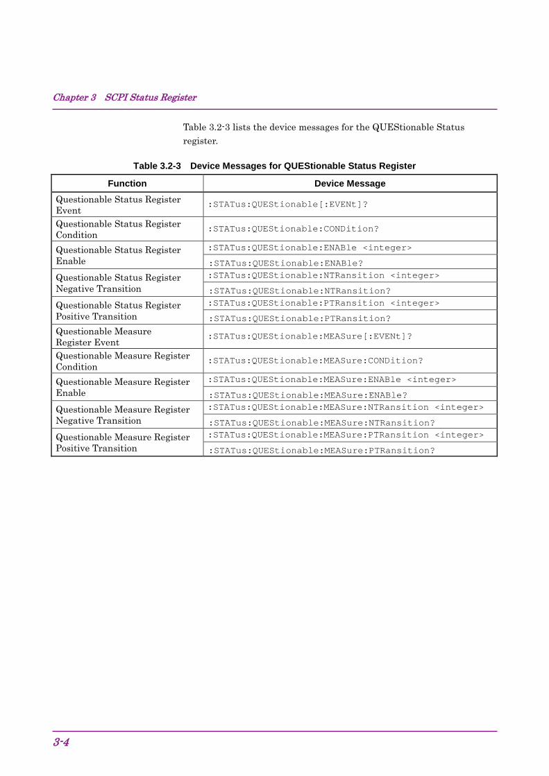
Chapter 3 SCPI Status Register
3-4
Table 3.2-3 lists the device messages for the QUEStionable Status register.
Table 3.2-3 Device Messages for QUEStionable Status Register
Function Device Message Questionable Status Register Event
:STATus:QUEStionable[:EVENt]?
Questionable Status Register Condition
:STATus:QUEStionable:CONDition?
Questionable Status Register Enable
:STATus:QUEStionable:ENABle <integer>
:STATus:QUEStionable:ENABle? Questionable Status Register Negative Transition
:STATus:QUEStionable:NTRansition <integer>
:STATus:QUEStionable:NTRansition? Questionable Status Register Positive Transition
:STATus:QUEStionable:PTRansition <integer>
:STATus:QUEStionable:PTRansition? Questionable Measure Register Event
:STATus:QUEStionable:MEASure[:EVENt]?
Questionable Measure Register Condition
:STATus:QUEStionable:MEASure:CONDition?
Questionable Measure Register Enable
:STATus:QUEStionable:MEASure:ENABle <integer>
:STATus:QUEStionable:MEASure:ENABle? Questionable Measure Register Negative Transition
:STATus:QUEStionable:MEASure:NTRansition <integer>
:STATus:QUEStionable:MEASure:NTRansition? Questionable Measure Register Positive Transition
:STATus:QUEStionable:MEASure:PTRansition <integer>
:STATus:QUEStionable:MEASure:PTRansition?
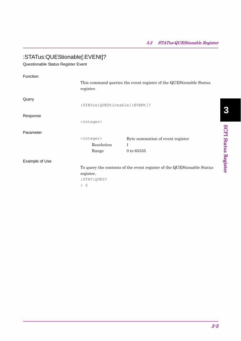
3.2 STATus:QUEStionable Register
3-5
3
SCPI Status Register
:STATus:QUEStionable[:EVENt]? Questionable Status Register Event Function
This command queries the event register of the QUEStionable Status register.
Query :STATus:QUEStionable[:EVENt]?
Response <integer>
Parameter <integer> Byte summation of event register
Resolution 1 Range 0 to 65535
Example of Use To query the contents of the event register of the QUEStionable Status register. :STAT:QUES?
> 0

Chapter 3 SCPI Status Register
3-6
:STATus:QUEStionable:CONDition? Questionable Status Register Condition Function
This command queries the condition register of the QUEStionable Status register.
Query :STATus:QUEStionable:CONDition?
Response <integer>
Parameter <integer> Byte summation of condition register
Resolution 1 Range 0 to 65535
Example of Use To query the content of the condition register of the QUEStionable Status register. :STAT:QUES:COND?
> 0

3.2 STATus:QUEStionable Register
3-7
3
SCPI Status Register
:STATus:QUEStionable:ENABle <integer> Questionable Status Register Enable Function
This command sets the event enable register of the QUEStionable Status register.
Command :STATus:QUEStionable:ENABle <integer>
Parameter <integer> Byte summation of event enable register
Resolution 1 Range 0 to 65535
Example of Use To set the event enable register of the QUEStionable Status Register to 16. :STAT:QUES:ENAB 16
:STATus:QUEStionable:ENABle? Questionable Status Register Enable Query Function
This command queries the event enable register of the QUEStionable Status register.
Query :STATus:QUEStionable:ENABle?
Response <integer>
Parameter <integer> Byte summation of event enable register
Resolution 1 Range 0 to 65535
Example of Use To query the event enable register of the QUEStionable Status Register. :STAT:QUES:ENAB?
> 16

Chapter 3 SCPI Status Register
3-8
:STATus:QUEStionable:NTRansition <integer> Questionable Status Register Negative Transition Function
This command sets the transition filter (negative transition) of the QUEStionable Status register.
Command :STATus:QUEStionable:NTRansition <integer>
Parameter <integer> Byte summation of transition filter (negative
transition) Resolution 1 Range 0 to 65535
Example of Use To set the transition filter (negative transition) of the QUEStionable Status register to 16. :STAT:QUES:NTR 16
:STATus:QUEStionable:NTRansition? Questionable Status Register Negative Transition Query Function
This command queries the transition filter (negative transition) of the QUEStionable Status register.
Query :STATus:QUEStionable:NTRansition?
Response <integer>
Parameter <integer> Byte summation of transition filter (negative
transition) Resolution 1 Range 0 to 65535
Example of Use To query the transition filter (negative transition) of the QUEStionable Status register. :STAT:QUES:NTR?
> 16
3.2 STATus:QUEStionable Register
3-9
3
SCPI Status Register
:STATus:QUEStionable:PTRansition <integer> Questionable Status Register Positive Transition Function
This command sets the transition filter (positive transition) of the QUEStionable Status register.
Command :STATus:QUEStionable:PTRansition <integer>
Parameter <integer> Byte summation of transition filter (positive
transition) Resolution 1 Range 0 to 65535
Example of Use To set the transition filter (positive transition) of the QUEStionable Status Register to 16. :STAT:QUES:PTR 16
:STATus:QUEStionable:PTRansition? Questionable Status Register Positive Transition Query Function
This command queries the transition filter (positive transition) of the QUEStionable Status Register.
Query :STATus:QUEStionable:PTRansition?
Response <integer>
Parameter <integer> Byte summation of transition filter (positive
transition) Resolution 1 Range 0 to 65535
Example of Use To query the transition filter (positive transition) of the QUEStionable Status Register. :STAT:QUES:PTR?
> 16

Chapter 3 SCPI Status Register
3-10
:STATus:QUEStionable:MEASure[:EVENt]? Questionable Measure Register Event Function
This command queries the event register of the QUEStionable Measure Register.
Query :STATus:QUEStionable:MEASure[:EVENt]?
Response <integer>
Parameter <integer> Byte summation of event register
Resolution 1 Range 0 to 65535
Example of Use To query the content of the event register of the QUEStionable Measure Register. :STAT:QUES:MEAS?
> 0

3.2 STATus:QUEStionable Register
3-11
3
SCPI Status Register
:STATus:QUEStionable:MEASure:CONDition? Questionable Measure Register Condition Function
This command queries the condition register of the QUEStionable Measure register.
Query :STATus:QUEStionable:MEASure:CONDition?
Response <integer>
Parameter <integer> Byte summation of condition register
Resolution 1 Range 0 to 65535
Example of Use To query the content of the condition register of the QUEStionable Measure register. :STAT:QUES:MEAS:COND?
> 0
Chapter 3 SCPI Status Register
3-12
:STATus:QUEStionable:MEASure:ENABle <integer> Questionable Measure Register Enable Function
This command sets the event enable register of the QUEStionable Measure register.
Command :STATus:QUEStionable:MEASure:ENABle <integer>
Parameter <integer> Byte summation of event enable register
Resolution 1 Range 0 to 65535
Example of Use To set the event enable register of the QUEStionable Measure register to 16. :STAT:QUES:MEAS:ENAB 16
:STATus:QUEStionable:MEASure:ENABle? Questionable Measure Register Enable Query Function
This command queries the event enable register of the QUEStionable Measure register.
Query :STATus:QUEStionable:MEASure:ENABle?
Response <integer>
Parameter <integer> Byte summation of event enable register
Resolution 1 Range 0 to 65535
Example of Use To query the event enable register of the QUEStionable Measure Register. :STAT:QUES:MEAS:ENAB?
> 16
3.2 STATus:QUEStionable Register
3-13
3
SCPI Status Register
:STATus:QUEStionable:MEASure:NTRansition <integer> Questionable Measure Register Negative Transition Function
This command sets the transition filter (negative transition) of the QUEStionable Measure register.
Command :STATus:QUEStionable:MEASure:NTRansition <integer>
Parameter <integer> Byte summation of transition filter (negative
transition) Resolution 1 Range 0 to 65535
Example of Use To set the transition filter (negative transition) of the QUEStionable Measure register to 16. :STAT:QUES:MEAS:NTR 16
:STATus:QUEStionable:MEASure:NTRansition? Questionable Measure Register Negative Transition Query Function
This command queries the transition filter (negative transition) of the QUEStionable Measure register.
Query :STATus:QUEStionable:MEASure:NTRansition?
Response <integer>
Parameter <integer> Byte summation of transition filter (negative
transition) Resolution 1 Range 0 to 65535
Example of Use To query the transition filter (negative transition) of the QUEStionable Measure register. :STAT:QUES:MEAS:NTR?
> 16

Chapter 3 SCPI Status Register
3-14
:STATus:QUEStionable:MEASure:PTRansition <integer> Questionable Measure Register Positive Transition Function
This command sets the transition filter (positive transition) of the QUEStionable Measure register.
Command :STATus:QUEStionable:MEASure:PTRansition <integer>
Parameter <integer> Byte summation of transition filter (positive
transition) Resolution 1 Range 0 to 65535
Example of Use To set the transition filter (positive transition) of the QUEStionable Measure register to 16. :STAT:QUES:MEAS:PTR 16
:STATus:QUEStionable:MEASure:PTRansition? Questionable Measure Register Positive Transition Query Function
This command queries the transition filter (positive transition) of the QUEStionable Measure register.
Query :STATus:QUEStionable:MEASure:PTRansition?
Response <integer>
Parameter <integer> Byte summation of transition filter (positive
transition) Resolution 1 Range 0 to 65535
Example of Use To query the transition filter (positive transition) of the QUEStionable Measure register. :STAT:QUES:MEAS:PTR?
> 16
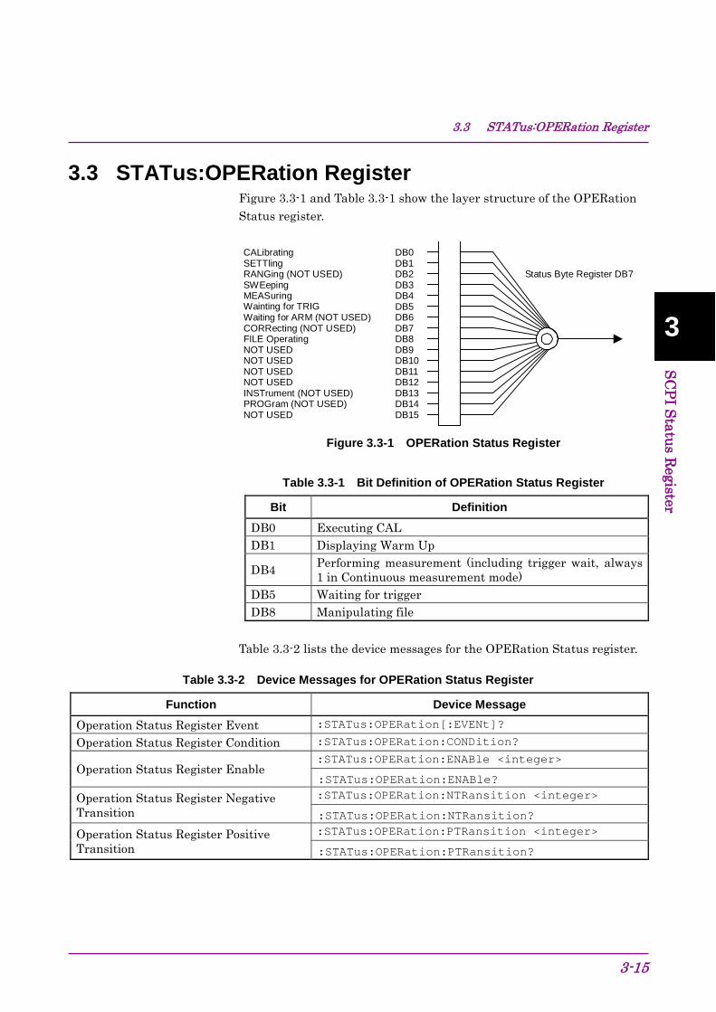
3.3 STATus:OPERation Register
3-15
3
SCPI Status Register
3.3 STATus:OPERation Register Figure 3.3-1 and Table 3.3-1 show the layer structure of the OPERation Status register.
CALibrating DB0 SETTling DB1 RANGing (NOT USED) DB2 SWEeping DB3 MEASuring DB4 Wainting for TRIG DB5 Waiting for ARM (NOT USED) DB6 CORRecting (NOT USED) DB7 FILE Operating DB8 NOT USED DB9 NOT USED DB10 NOT USED DB11 NOT USED DB12 INSTrument (NOT USED) DB13 PROGram (NOT USED) DB14 NOT USED DB15
Status Byte Register DB7
Figure 3.3-1 OPERation Status Register
Table 3.3-1 Bit Definition of OPERation Status Register
Bit Definition DB0 Executing CAL DB1 Displaying Warm Up
DB4 Performing measurement (including trigger wait, always 1 in Continuous measurement mode)
DB5 Waiting for trigger DB8 Manipulating file
Table 3.3-2 lists the device messages for the OPERation Status register.
Table 3.3-2 Device Messages for OPERation Status Register
Function Device Message Operation Status Register Event :STATus:OPERation[:EVENt]?
Operation Status Register Condition :STATus:OPERation:CONDition?
Operation Status Register Enable :STATus:OPERation:ENABle <integer>
:STATus:OPERation:ENABle? Operation Status Register Negative Transition
:STATus:OPERation:NTRansition <integer>
:STATus:OPERation:NTRansition? Operation Status Register Positive Transition
:STATus:OPERation:PTRansition <integer>
:STATus:OPERation:PTRansition?
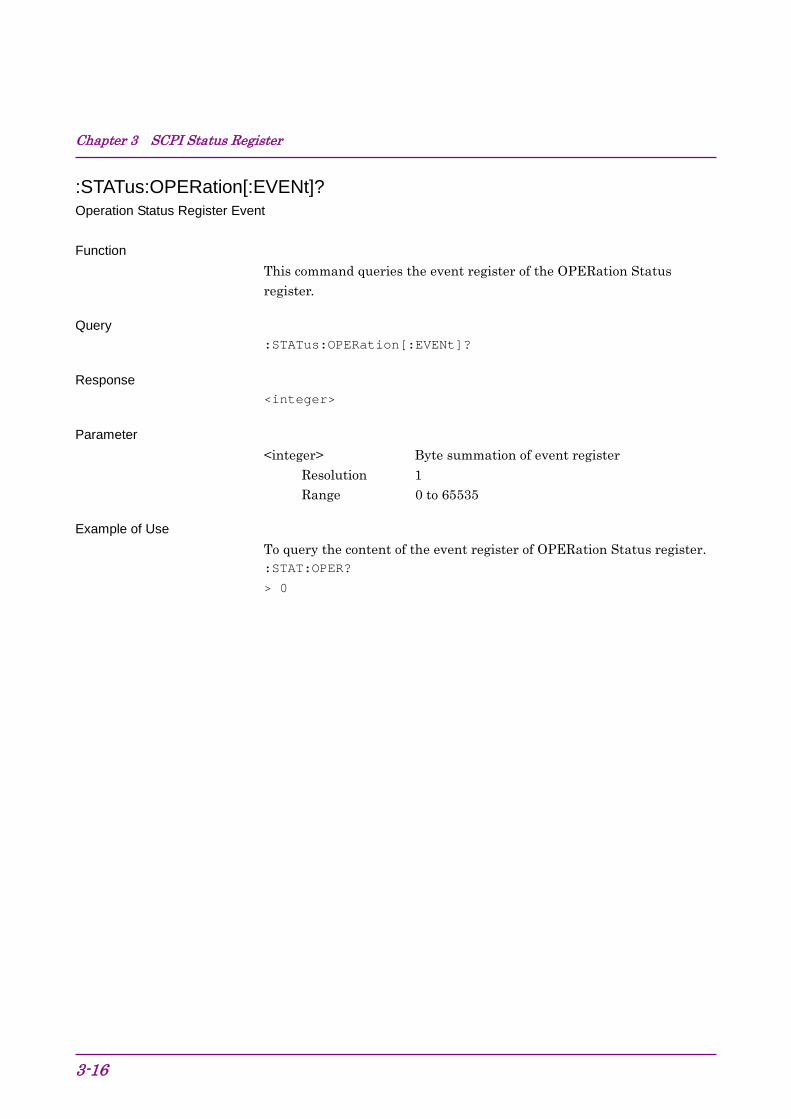
Chapter 3 SCPI Status Register
3-16
:STATus:OPERation[:EVENt]? Operation Status Register Event Function
This command queries the event register of the OPERation Status register.
Query :STATus:OPERation[:EVENt]?
Response <integer>
Parameter <integer> Byte summation of event register
Resolution 1 Range 0 to 65535
Example of Use To query the content of the event register of OPERation Status register. :STAT:OPER?
> 0

3.3 STATus:OPERation Register
3-17
3
SCPI Status Register
:STATus:OPERation:CONDition? Operation Status Register Condition Function
This command queries the condition register of the OPERation Status Register.
Query :STATus:OPERation:CONDition?
Response <integer>
Parameter <integer> Byte summation of condition register
Resolution 1 Range 0 to 65535
Example of Use To query the content of the condition register of the OPERation Status register. :STAT:OPER:COND?
> 0

Chapter 3 SCPI Status Register
3-18
:STATus:OPERation:ENABle <integer> Operation Status Register Enable Function
This command sets the event enable register of the OPERation Status register.
Command :STATus:OPERation:ENABle <integer>
Parameter <integer> Byte summation of event enable register
Resolution 1 Range 0 to 65535
Example of Use To set the event enable register of the OPERation Status register to 16. :STAT:OPER:ENAB 16
:STATus:OPERation:ENABle? Operation Status Register Enable Query Function
This command queries the event enable register of the OPERation Status register.
Query :STATus:OPERation:ENABle?
Response <integer>
Parameter <integer> Byte summation of event enable register
Resolution 1 Range 0 to 65535
Example of Use To query the event enable register of the OPERation Status register. :STAT:OPER:ENAB?
> 16

3.3 STATus:OPERation Register
3-19
3
SCPI Status Register
:STATus:OPERation:NTRansition <integer> Operation Status Register Negative Transition Function
This command sets the transition filter (negative transition) of the OPERation Status register.
Command :STATus:OPERation:NTRansition <integer>
Parameter <integer> Byte summation of transition filter (negative
transition) Resolution 1 Range 0 to 65535
Example of Use To set the transition filter (negative transition) of the OPERation Status register to 16. :STAT:OPER:NTR 16
:STATus:OPERation:NTRansition? Operation Status Register Negative Transition Query Function
This command queries the transition filter (negative transition) of the OPERation Status register.
Query :STATus:OPERation:NTRansition?
Response <integer>
Parameter <integer> Byte summation of transition filter (negative
transition) Resolution 1 Range 0 to 65535
Example of Use To query the transition filter (negative transition) of the OPERation Status register. :STAT:OPER:NTR?
> 16

Chapter 3 SCPI Status Register
3-20.
:STATus:OPERation:PTRansition <integer> Operation Status Register Positive Transition Function
This command sets the transition filter (positive transition) of the OPERation Status register.
Command :STATus:OPERation:PTRansition <integer>
Parameter <integer> Byte summation of transition filter (positive
transition) Resolution 1 Range 0 to 65535
Example of Use To set the transition filter (positive transition) of the OPERation Status register to 16. :STAT:OPER:PTR 16
:STATus:OPERation:PTRansition? Operation Status Register Positive Transition Query Function
This command queries the transition filter (positive transition) of the OPERation Status register.
Query :STATus:OPERation:PTRansition?
Response <integer>
Parameter <integer> Byte summation of transition filter (positive
transition) Resolution 1 Range 0 to 65535
Example of Use To query the transition filter (positive transition) of the OPERation Status register. :STAT:OPER:PTR?
> 16