Embed Size (px)
Citation preview

F i e l d I m p l e m e n t a t i o n M a n u a l, 2F i e l d I m p l e m e n t a t i o n M a n u a l, 2ndnd Edition Edition
Solar Home System Installation and Operations Manual
NOTE: This Chapter is taken from the NOTE: This Chapter is taken from the AMORE Field Operations ManualAMORE Field Operations Manual
Solar Home System Installation, Solar Home System Installation, Operations and Maintenance ManualOperations and Maintenance Manual
For theBarangay Renewable Energy Cooperativeand Development Association (BRECDA)
This manual is property of :
----------------------------------------------------------Barangay :
----------------------------------------------------------Municipality
: ----------------------------------------------------------
Chapter 3:Chapter 3: 35 of 77of 77
Alliance for Mindanao Off-Grid Renewable Energy (AMORE)

F i e l d I m p l e m e n t a t i o n M a n u a l, 2F i e l d I m p l e m e n t a t i o n M a n u a l, 2ndnd Edition Edition
Solar Home System Installation and Operations Manual
Contents
Doc. No. Description00 Renewable Energy System Technical Maintenance01 Introduction0203 BCS Ampere Hour Meter – Trimetric04 Solar Module Specification Sheet05 BCS Monthly Maintenance Sheets
Chapter 3:Chapter 3: 36 of 77of 77

F i e l d I m p l e m e n t a t i o n M a n u a l, 2F i e l d I m p l e m e n t a t i o n M a n u a l, 2ndnd Edition Edition
Solar Home System Installation and Operations Manual
1. INTRODUCTION1. INTRODUCTION
The Alliance for Mindanao Off-Grid Renewable Energy (AMORE) Project is tasked to electrify some 160 barangays in Mindanao using renewable energy systems. To provide long-term technical support and maintenance of the installed systems, the AMORE project will involve the participation of strategic service centers and qualified technicians to do commercial repair and maintenance. These service centers and technicians will be trained, provided access to spare parts and manuals and certified to conduct repair and maintenance on the AMORE renewable energy systems and components.
While in the barangay level, the Barangay Renewable Energy Cooperative and Development Associations (BRECDA) who manage and operate these systems can then commercially request the service centers and service personnel for high-level repair and maintenance.
When the funds for repair and maintenance are successfully collected by BRECDA and with the accessibility local service centers and spare parts, the operational lifetime of installed RE systems will be optimized.
Chapter 3:Chapter 3: 37 of 77of 77

F i e l d I m p l e m e n t a t i o n M a n u a l, 2F i e l d I m p l e m e n t a t i o n M a n u a l, 2ndnd Edition Edition
Solar Home System Installation and Operations Manual
2. TECHNICAL MAINTENANCE2. TECHNICAL MAINTENANCE SUPPORT SCHEMESUPPORT SCHEME
Effective maintenance can be actualised by the availability of funds, access to qualified personnel and access to spare parts. Lacking any one of these requirements, effective system repair and maintenance may not occur.
While the availability and collection of O&M funds is a prime role of BRECDA, the renewable energy systems need to be operational and with minimal downtime to optimize its fund collection.
An operator does the barangay maintenance and repair, do household wirings, but for high level maintenance, more advanced tools and understanding is required which are available only at the service centers.
The advantages of the local service centers and technicians are apparent in terms of accessibility, which translate to lower transport and repair cost. This can then minimize the downtime of the RE system. The capabilities of the local service center will have to be improved in terms of spare parts, diagrams, manuals and access to required equipment.
3. ROLE OF AMORE 3. ROLE OF AMORE
o Provide institutional and developmental support to BRECDA.o Provide electrification by installing RE systems.o Train BRECDA operators and technicians.o Train and certify local service centers and technicians.o Provide access to spare parts and diagrams.o Conduct maintenance visits to systems prior to handover.
4. ROLE OF BRECDA 4. ROLE OF BRECDA
Properly manage and operate the systems.Optimize O&M fund collection.
Chapter 3:Chapter 3: 38 of 77of 77

F i e l d I m p l e m e n t a t i o n M a n u a l, 2F i e l d I m p l e m e n t a t i o n M a n u a l, 2ndnd Edition Edition
Solar Home System Installation and Operations Manual
5. ROLE OF SERVICE CENTER AND TECHNICIANS5. ROLE OF SERVICE CENTER AND TECHNICIANS
Provide commercial support to BRECDA.
Chapter 3:Chapter 3: 39 of 77of 77

F i e l d I m p l e m e n t a t i o n M a n u a l, 2F i e l d I m p l e m e n t a t i o n M a n u a l, 2ndnd Edition Edition
Solar Home System Installation and Operations Manual
1. SOLAR HOME SYSTEM1. SOLAR HOME SYSTEM
A Solar Home System (SHS) consist of components that turns sunlight into dc electricity to power electricity consuming devices. The brighter the sunlight, more electricity is produced. During rainy days where there is less sunlight, little electricity is produced. No electricity is produced at night.
Electricity can be stored and drawn anytime from batteries for night use.
.Figure 1. Solar Home System Block Diagram
A Solar Home System consists of the following:
a. PV module/PV panel generates dc electricity.b. Battery charge controller (BCC) controls charging and
discharging of the battery.c. Battery-storage of electrical energy.d. Load or the appliances.
Chapter 3:Chapter 3: 40 of 77of 77

F i e l d I m p l e m e n t a t i o n M a n u a l, 2F i e l d I m p l e m e n t a t i o n M a n u a l, 2ndnd Edition Edition
Solar Home System Installation and Operations Manual
2. COMPONENTS IN A 2. COMPONENTS IN A SOLAR HOME SYSTEMSOLAR HOME SYSTEM
2.1 PV MODULE
In a photovoltaic system, the part that converts sunlight to electricity is called a photovoltaic module. Place it where there is plenty of sunshine and you have electricity.
FACTORS AFFECTING ELECTRICITY OUTPUT
A. MODULE AREA
More PV modules mean more electricity is produced. A 50 Watt PV module can produce 200Watt-hours of electricity. Double a 50Wp module and you get 400 Watt-hours of electricity.
B. BRIGHTNESS OF THE SUN
PV module power output is sensitive to the sun. Sunny clear days mean more electricity is produce. Overcast or cloudy skies mean less electricity from the PV module. Rainy days means very little electricity is produced.
C. PV MODULE ORIENTATION
To get most electricity from a PV module, it must face towards the sun. Therefore it must be oriented to the South.
2.2. BATTERY CHARGE CONTROLLERS (BCC)
A battery charge controller ( BCC ) controls charging and discharging of the battery. Overcharging causes the battery to gas thereby releasing hydrogen and oxygen gases which lead to water loss. Deep discharging causes the plates to evolve to sulphate crystal which is an insulator. Sulphates when flaked off to the bottom of the container cannot be charged back to lead and lead dioxide.
TYPES OF BATTERY CHARGE CONTROLLER
A. SERIES TYPE
In a SERIES type controller, the PV module is switched off when the battery reaches 14.4 Volts thereby charging of the battery is discontinued. When the battery voltage lowers to 13.5 Volts, the PV module is reconnected to the battery thereby charging is resumed.
Chapter 3:Chapter 3: 41 of 77of 77

F i e l d I m p l e m e n t a t i o n M a n u a l, 2F i e l d I m p l e m e n t a t i o n M a n u a l, 2ndnd Edition Edition
Solar Home System Installation and Operations Manual
B. SHUNT TYPE CONTROLLER
In a SHUNT type controller, charging of the battery is discontinued by throwing away the excess electricity from the PV module. When the battery reaches again a certain voltage, charging is resumed.
Note that the short-circuit action does not damage the PV module or controller.
2.3. BATTERYThe battery stores electricity produced by the PV module. At night, the load can draw electricity from the battery. It also serves as a buffer for the load.
2.4. LOADThe loads in a PV system are the energy consuming devices such as lights, TV sets, AM/FM radios/cassettes, etc.
Chapter 3:Chapter 3: 42 of 77of 77

F i e l d I m p l e m e n t a t i o n M a n u a l, 2F i e l d I m p l e m e n t a t i o n M a n u a l, 2ndnd Edition Edition
Solar Home System Installation and Operations Manual
3. HOW TO SELECT 3. HOW TO SELECT COMPONENT LOCATIONCOMPONENT LOCATION
3.1. PV ARRAY LOCATIONThe PV module is best located in places where it is facing the sun unobstructed during the day. The location should be free from any object such as trees, shrubs and houses that may cast a shadow on the PV module face over its lifetime. It should also be as close as possible to the battery and battery charge controller to minimize voltage drop in the cables.
3.2. BATTERY CHARGE CONTROLLER LOCATIONThe Battery Charge Controller (BCC) is the link between the PV module, battery and load. The BCC should be mounted within 10 meters of the PV module, 2 meters from the battery and 10 meters from the load distribution junction box.
It should be mounted vertically, preferably on a wall, in a highly visible location and where children cannot have access to it.
3.3. STORAGE BATTERY LOCATIONThe storage battery should be located in an indoor location. It should be in an easily accessible place for regular battery maintenance. Whenever possible, batteries should be enclosed in a well-ventilated box constructed from wood or plastic. It should allow for access of maintenance and safe lifting, sliding for removal of batteries when necessary. Any person other than the technician should close the box with a lock or other means to prevent casual contact.
3.4. LIGHTING FIXTURE LOCATIONThe lighting fixture is best situated where it can give the most light. It should be high enough so that people will not bump into it. It should not be too high to compromise illumination levels.
4. TOOLS AND 4. TOOLS AND EQUIPMENT USED IN A EQUIPMENT USED IN A SOLAR INSTALLATIONSOLAR INSTALLATION
Chapter 3:Chapter 3: 43 of 77of 77

F i e l d I m p l e m e n t a t i o n M a n u a l, 2F i e l d I m p l e m e n t a t i o n M a n u a l, 2ndnd Edition Edition
Solar Home System Installation and Operations Manual
4.1. TOOLS SELECTION
Some tools for installing and maintaining PV power systems are needed. Careful planning of the installation process will help prevent loss of time due to missing tools and accessories.
4.2. REQUIRED TOOLS Digital Voltmeter, with at least 10 Amp current capability,
spare batteries Compass Tilt angle indicator, or protractor Measuring tape Wrenches: Specific sizes for all mounting bolts Screw Drivers: Flat blade in sizes for all mounting
hardware; Philips in all sizes for all mounting hardware; Small jewelry size for adjusting controls.
Soldering Tools (gas or electric) Wire Crimping, Stripping and Cutting tools Electrical Tape Miscellaneous for connections: Split bolts, wire nuts,
lugs, etc. Hammer Metal Hack saw, Wood saw , Chisel Socket Wrench
Figure
2. Tools for a PV technician.
Chapter 3:Chapter 3: 44 of 77of 77

F i e l d I m p l e m e n t a t i o n M a n u a l, 2F i e l d I m p l e m e n t a t i o n M a n u a l, 2ndnd Edition Edition
Solar Home System Installation and Operations Manual
5. HOW TO INSTALL A 5. HOW TO INSTALL A SOLAR HOME SYSTEMSOLAR HOME SYSTEM
5.1 PV MODULE WIRING Cut the two-conductor Royal cord, no. 12 AWG to the
required length (not more than 15 m.). Strip one end of the Royal cord of its insulation about 4 inches using a cable stripper or a knife.
(a). Stripping of Royal Cord with a knife
Strip the conductors of 5 mm of its insulation and insert bayonet crimps into the stranded conductor. Crimp using a crimping pliers. Pull the cable to test tightness of the crimp made. If it is loose, crimp the conductor again.
Bayonet Crimp
Chapter 3:Chapter 3: 45 of 77of 77

F i e l d I m p l e m e n t a t i o n M a n u a l, 2F i e l d I m p l e m e n t a t i o n M a n u a l, 2ndnd Edition Edition
Solar Home System Installation and Operations Manual
(b) (c)
(b) Stripped conductor ready for crimping.(c) Crimping conductor with crimping plier.
Pass the cable through the cable glands on the side of the PV module junction box as shown below.
(d) Royal Cord through cable glands
Tighten the cable glands so that a tight seal is formed around the cable. Replace the PV module junction box cover.
5.2. PV MODULE MOUNTING Mount the PV module using the support structures
provided for.
Lay the PV module face down so that the aluminum frame faces upward.
Place the support bars on the aluminum frame of the PV module. Secure with the bolts and nuts provided. Tighten afterwards the bolts with a wrench.
Cable Gland
Chapter 3:Chapter 3: 46 of 77of 77

F i e l d I m p l e m e n t a t i o n M a n u a l, 2F i e l d I m p l e m e n t a t i o n M a n u a l, 2ndnd Edition Edition
Solar Home System Installation and Operations Manual
(e) (f) (e) PV module mounted on aluminum frame; (f) PV module mounted on steel post and secured with a 2 inches U-Bolt, Place the two inches U-bolt on the center bar. The PV
module is now ready for mounting to steel pole. Frame is fabricated, already tilted at the desired angle.
NOTE: To obtain maximum output from the solar module (and hence maximum number of hours lightning) the solar module must be mounted such that it is tilted whilst still facing the equator. The tilt angle of the PV module should equal the site latitude, but should not be less than 10 degrees for self cleaning purposes. Table 1 shows the recommended tilt angle for different provinces in the Philippines.
Chapter 3:Chapter 3: 47 of 77of 77

F i e l d I m p l e m e n t a t i o n M a n u a l, 2F i e l d I m p l e m e n t a t i o n M a n u a l, 2ndnd Edition Edition
Solar Home System Installation and Operations Manual
Table 1. RECOMMENDED MODULE TILT ANGLES BY PROVINCE
PROVINCE TILT PROVINCE TILTABRA 18 LANAO DEL SUR 10AGUSAN DEL NORTE 10 LEYTE 11AGUSAN DEL SUR 10 MAGUINDANAO 10AKLAN 12 MARINDUQUE 10ALBAY 13 MASBATE 12ANTIQUE 11 MISAMIS OCCIDENTAL 10APAYAO 18 MISAMIS ORIENTAL 10AURORA 16 MOUNTAIN PROVINCE 17BASILAN 10 NCR 15BATAAN 15 NEGROS OCCIDENTAL 10BATANES 21 NEGROS ORIENTAL 10BATANGAS 14 NORTH COTABATO 10BENGUET 17 NORTHERN SAMAR 12BILIRAN 12 NUEVA ECIJA 16BOHOL 10 NUEVA VIZCAYA 16BUKIDNON 10 OCCIDENTAL MINDORO 13BULACAN 15 ORIENTAL MINDORO 13CAGAYAN 18 PALAWAN 10CAMARINES NORTE 14 PAMPANGA 15CAMARINES SUR 14 PANGASINAN 16CAMIGUIN 10 QUEZON 14CAPIZ 11 QUIRINO 16CATANDUANES 14 RIZAL 15CAVITE 14 ROMBLON 12CEBU 10 SARANGANI 10DAVAO 10 SIQUIJOR 10DAVAO DEL SUR 10 SORSOGON 13DAVAO ORIENTAL 10 SOUTHERN COTABATO 10EASTERN SAMAR 12 SOUTHERN LEYTE 10GUIMARAS 11 SULTAN KUDARAT 10IFUGAO 17 SULU 10ILOCOS NORTE 18 SURIGAO DEL NORTE 10ILOCOS SUR 17 SURIGAO DEL SUR 10ILOILO 11 TARLAC 15ISABELA 17 TAWI-TAWI 10KALINGA 17 WESTERN SAMAR 12LA UNION 17 ZAMBALES 15LAGUNA 14 ZAMBOANGA DEL NORTE 10LANAO DEL NORTE 10 ZAMBOANGA DEL SUR 10
5.3. POLE PREPARATION
WALL MOUNTED POLE
Drill a ¼ in. diameter hole at the end of a two-inch-diameter, 20 feet steel pipe to accommodate the dowel at the center of the U-bolt.
Cut the G.I. pole using a hacksaw approximately three inches crosswise, as shown below, and cut about 2/3 of the pipe diameter lengthwise at the end of the crosswise cut.
Chapter 3:Chapter 3: 48 of 77of 77

F i e l d I m p l e m e n t a t i o n M a n u a l, 2F i e l d I m p l e m e n t a t i o n M a n u a l, 2ndnd Edition Edition
Solar Home System Installation and Operations Manual
(h)
(g) Steel pole cut horizontally and vertically; (h) (h) stretched-out portion of the cut pole.
Stretch the cut-out portion using a vise grip and flatten with a hammer. Drill holes on the flaps of the pole about ¼ inch in diameter.
Place the PV module already mounted on the aluminum frame on top of the pole. Insert the U-bolt in the center hole of the aluminum center bar, pressing in between the steel pole. Tighten the U-bolt with a wrench.
Place the Royal Cord alongside the steel pole and fasten it tightly using a cable tie.
(g)
Chapter 3:Chapter 3: 49 of 77of 77

F i e l d I m p l e m e n t a t i o n M a n u a l, 2F i e l d I m p l e m e n t a t i o n M a n u a l, 2ndnd Edition Edition
Solar Home System Installation and Operations Manual
Fasten the steel pole with PV module in an upright position. Secure it along the wall, using pipe champs. Screw the steel pole on the wall for additional support.
The Royal Cord should be
laid-out going to the BCC and fastened along the wall or ceiling with a ½ in. cable clamp. The ends of the Royal Cord should be stripped and crimped as shown in Figure 1.1.a and b.
The cable is now ready to be connected to the Battery Charge Controller.
(i) Royal Cord fastened by cable tie onto steel post.
5.4. HOW TO INSTALL THE BCC:
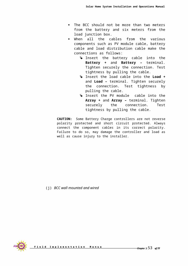
Mount the BCC vertically on a wall. Fasten the BCC with wood screw securely to the wall. The BCC should not be more than two meters from the
battery and six meters from the load junction box. When all the cables from the various components such as
PV module cable, battery cable and load distribution cable make the connections as follows:
Insert the battery cable into the Battery + and Battery – terminal. Tighten securely the connection. Test tightness by pulling the cable.
Insert the load cable into the Load + and Load – terminal. Tighten securely the connection. Test tightness by pulling the cable.
Chapter 3:Chapter 3: 50 of 77of 77

F i e l d I m p l e m e n t a t i o n M a n u a l, 2F i e l d I m p l e m e n t a t i o n M a n u a l, 2ndnd Edition Edition
Solar Home System Installation and Operations Manual
Insert the PV module cable into the Array + and Array – terminal. Tighten securely the connection. Test tightness by pulling the cable.
CAUTION: Some Battery Charge controllers are not reverse polarity protected and short circuit protected. Always connect the component cables in its correct polarity. Failure to do so, may damage the controller and load as well as cause injury to the installer.
(j) BCC wall mounted and wired
(k) PV module, battery and load connected to BCC
5.5. HOW TO INSTALL THE BATTERY
Filling-up of battery solution in a battery
Chapter 3:Chapter 3: 51 of 77of 77

F i e l d I m p l e m e n t a t i o n M a n u a l, 2F i e l d I m p l e m e n t a t i o n M a n u a l, 2ndnd Edition Edition
Solar Home System Installation and Operations Manual
Ð Remove the plastic cover,
for a new battery. Remove the seal on each cap of the cell to expose the vent holes. Remove the cap afterwards.
Ð Using a funnel, pour the battery solution in each cell. Be careful not to overflow the battery as the solution is a corrosive acid which can cause burns on the skin as well as damage clothes.
Ð Wipe-off excess solution on the surface of the battery using a rag.
Ð Prepare the battery cable for connection to the battery charge controller as described in Figure b and c.
Ð On the other end of the cable going to the battery, connect the battery cable by means of battery clips or clamps.
Ð Lay out and fasten securely the battery cable along the wall going to the controller by means of ½ in. cable clamps.
Ð The sequences of connecting the battery to the BCC are as follows.
1. On the upper part of the cable, POSITIVE + terminal followed by the NEGATIVE – terminal to the BCC.2. On the lower end of the battery cable, POSITIVE + terminal of the cable to the POSITIVE + terminal of the battery followed by the NEGATIVE – terminal of the cable to the NEGATIVE -- terminal of the battery.
Ð Tighten the connections as loose connections on the battery terminals can cause arcing.
Ð Apply battery grease or plain grease on the battery terminals to prevent corrosion. If these are not available VULCASEAL is suggested to be used instead.
5.5.1 Measuring the SoC of a battery with the multimeter
Chapter 3:Chapter 3: 52 of 77of 77
F i e l d I m p l e m e n t a t i o n M a n u a l, 2F i e l d I m p l e m e n t a t i o n M a n u a l, 2ndnd Edition Edition
Solar Home System Installation and Operations Manual
If you want a more detailed SoC of the battery than that indicated by the LEDs of the SDU, you can measure it with a Voltmeter. Note that with this procedure, you can know the SoC of the battery at a specific moment, but you cannot say anything about the quality or the ageing of the battery!
Follow these steps:Make sure the battery has been at rest for at least 1 hour, but preferably more.Make sure there is no load connected.Open the front of the SDU.Check the voltage over the poles and compare the result with the suppliers specifications (see for a sample). Note down the results in the appropriate place.
Specific gravity at 25º Open Voltage Voc SoC (%) Interpretation1.25 kg/ltr. 12.7 V 100 % Fully charged1.23 kg/ltr. 12.5 V 80 % Full1.20 kg/ltr. 12.2 V 60 % Half1.16 kg/ltr. 12.0 V 40 % Empty1.12 kg/ltr. 11.7 V 20 % Completely empty
Table 1: Specific gravity and Open Voltage as indicators of the State of Charge of a battery.
Note that this table is just a rough indication and that real-life tables or graphs must be obtained from the battery supplier. Also keep in mind that the values measured are temperature dependent: measurements taken at temperatures above the specified will yield flattered results.
5.5.2. MEASURING THE SOC OF A BATTERY WITH THE HYDROMETER
The hydrometer measures the specific gravity (also called density) of the sulphuric acid in each cell, which is directly related to the SoC. This operation is more precise, but more cumbersome than the measuring with the multimeter. It also provides additional information, as it determines differences between the cells.
Follow these steps to determine the SoC of the battery with a hydrometer:Execute this test before refilling the battery with de-ionised water, as refilling will affect the results.
Contrary to the measuring with the voltmeter, you do not need to have the battery rested or the loads disconnected.
Suck sulphuric acid from the first cell up into the hydrometer.
Figure 25: Batteries are dangerous! They must be maintained by qualified persons
only. Keep away from open fire and store in a ventilated space. Beware of spilled
battery acid. In case acid was spilled, rinse with plenty of water.
Figure 26: High and low state of charge of the
battery.
Chapter 3:Chapter 3: 53 of 77of 77

F i e l d I m p l e m e n t a t i o n M a n u a l, 2F i e l d I m p l e m e n t a t i o n M a n u a l, 2ndnd Edition Edition
Solar Home System Installation and Operations Manual
Read the specific density from the scale floating in the acid. Note down the value.
Reject the acid in the same cell as where you drew it from. Do not mix acid between cells!
Repeat steps 3 to 5 for the other cells of the battery.
Calculate the average specific gravity and compare it to the supplier’s specifications (see ).
Note down the results in the SHS logbook.
From the range of 6 specific gravity’s, find the highest and the lowest value. If the difference is more than 0.01 kg/ltr., the battery has a problem and may benefit from boost charging. If needed, boost charge the battery by charging it with an external power source of by disconnecting the loads for several days.
If hereafter the difference persists, the battery has reached its life’s end and needs to be replaced.
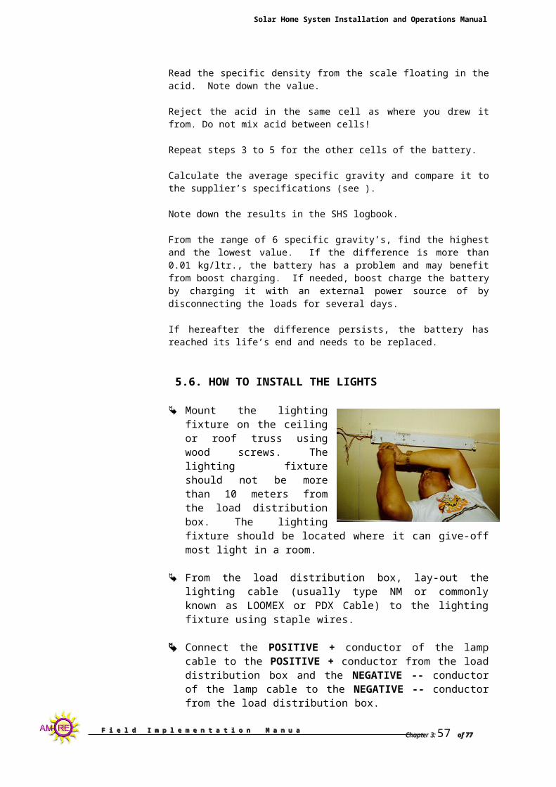
5.6. HOW TO INSTALL THE LIGHTS
Mount the lighting fixture on the ceiling or roof truss using wood screws. The lighting fixture should not be more than 10 meters from the load distribution box. The lighting fixture should be located where it can give-off most light in a room.
From the load distribution box, lay-out the lighting cable (usually type NM or commonly known as LOOMEX or PDX Cable) to the lighting fixture using staple wires.
Connect the POSITIVE + conductor of the lamp cable to the POSITIVE + conductor from the load distribution box and the NEGATIVE -- conductor of the lamp cable to the NEGATIVE -- conductor from the load distribution box.
Splice the conductors by twisting the conductors together with a plier. Tape afterwards with an electrical tape.
Splice the lamp, switch and load distribution cable in the load distribution junction box as shown below. Check the connections for shorts in the connections before taping with an electrical tape.
Checking for short circuit on the connection.
Chapter 3:Chapter 3: 54 of 77of 77

F i e l d I m p l e m e n t a t i o n M a n u a l, 2F i e l d I m p l e m e n t a t i o n M a n u a l, 2ndnd Edition Edition
Solar Home System Installation and Operations Manual
Set the multimeter to RESISTANCE setting. With the switch on “OFF mode” connect the multimeter probes on the splice. If there is no short-circuit in the connection, the meter should read an open connection. If a short-circuit in the connection is present, an OHM reading close to zero or zero can be read in the meter. In digital multimeters, a short circuit reading is accompanied by a beeping sound.
For a number of lamps installed, follow the above mentioned steps. In the light distribution junction box, the lamps are connected in parallel with the LOAD conductors from the battery charge controller.
Chapter 3:Chapter 3: 55 of 77of 77

F i e l d I m p l e m e n t a t i o n M a n u a l, 2F i e l d I m p l e m e n t a t i o n M a n u a l, 2ndnd Edition Edition
Solar Home System Installation and Operations Manual
Shown below is the Solar Home System Lay-out and Block Diagram
Solar Home System Block Diagram
Chapter 3:Chapter 3: 56 of 77of 77
F i e l d I m p l e m e n t a t i o n M a n u a l, 2F i e l d I m p l e m e n t a t i o n M a n u a l, 2ndnd Edition Edition
Solar Home System Installation and Operations Manual
6. COMMISSIONING6. COMMISSIONING
The Solar Home Lighting System should be tested and commissioned before the installer leave the site. All fuses and disconnects as well as switches should be tested and cycled. All loads should be operated. The installer should explain to the user the commissioning report as well as routine maintenance such as topping up of battery with distilled water and cleaning of lighting fixture. The user shall sign the Commissioning Report and a copy shall be left in the users’ care.
Shown in next page is the recommended Commissioning Report.
Chapter 3:Chapter 3: 57 of 77of 77

F i e l d I m p l e m e n t a t i o n M a n u a l, 2F i e l d I m p l e m e n t a t i o n M a n u a l, 2ndnd Edition Edition
Solar Home System Installation and Operations Manual
CERTIFICATE OF COMMISSIONINGCERTIFICATE OF COMMISSIONINGTHIS IS TO CERTIFY THAT
component of a Solar Home Systems listed below were received in good condition.
COMPONENT QUANTITY SERIAL NO.PV Module: _____ Wp _________ _________________Battery charge controller _____A _________ _________________Fluorescent Lamp ______ W _________ _________________Fluorescent Lamp ___W _________ _________________Royal Cable No. 12/2 AWG ________mFlat cord No. 12/2 ________mTumbler Switch ________ pcs.Junction Box ________ pcs.Aluminum Frame ________ setG.I. Pipe, 2 in. dia., Sch. 20 ________ pcs
This further certifies that the components have been installed and functional tests have been performed by the installer in my presence and that all components are working and without defects.
END-USER: DATE INSTALLED:
______________________________ ____________________________PRINTED NAME/SIGNATURE
INSTALLER LOCATION______________________________ _____________________________
EQUIPMENT LOCATION PLAN
North Battery Chg. Junction Box
Controller
PV module Light DC/DC Converter
Battery -------S Switch Outlet
JBBCC
Chapter 3:Chapter 3: 58 of 77of 77

F i e l d I m p l e m e n t a t i o n M a n u a l, 2F i e l d I m p l e m e n t a t i o n M a n u a l, 2ndnd Edition Edition
Solar Home System Installation and Operations Manual
7.0 SAFETY7.0 SAFETY PRECAUTIONSPRECAUTIONS
7.1. GENERAL SAFETY
Establish and enforce safety procedures. Follow Electrical Codes and local codes. All conductors
should have disconnecting means such as fuses, safety switches or circuit breakers.
Cover array with blanket or other opaque cover when servicing system to reduce hazard of electrical shock.
Use ladders appropriately when required especially when working on high places such as installing the lights and solar module.
Always wear rubber gloves and safety glasses when working with batteries.
CONDITIONS FOR SAFETY WHEN WORKING WITH BATTERIES
Keep open flames and sparks away from battery area. Use protective gears such as safety goggles, acid-
resistant gloves, funnels and aprons when filling batteries with battery solution (sulfuric acid).
Disconnect battery bank from any sources of charging or discharging before working on batteries.
Have exposed battery terminals covered by strong non-conducting caps or covers.
Design battery area with adequate ventilation, and adequate protection from the environment.
Lift the battery only the manner approved by the manufacturer, and never at the terminal post.
Batteries contain acid which may damage clothing and cause burns on the skin. When acid gets in to the eyes, immediately flush with water
7.3. TOOLS
Use proper tools for assembling panels and other components.
Tools should be shorter than the length between terminal post, to reduce the possibility of dropping and causing short circuit.
Have non-working or grip end of metal tools covered with strong non-conductive plastic coating or tape.
Chapter 3:Chapter 3: 59 of 77of 77

F i e l d I m p l e m e n t a t i o n M a n u a l, 2F i e l d I m p l e m e n t a t i o n M a n u a l, 2ndnd Edition Edition
Solar Home System Installation and Operations Manual
8.0.8.0. MAINTENANCE OF MAINTENANCE OF SOLAR HOME LIGHTINGSOLAR HOME LIGHTING SYSTEM (USER LEVEL)SYSTEM (USER LEVEL)
Good operation of the Solar Home System consists mainly on how the user maintained their systems. Constant information dissemination on part of the user about maintenance should do the trick.
8.1. PV MODULE
PV Module will require nothing but an occasional cleaning of a dry cloth. Dust and dirt may accumulate on the PV module surface, gradually reducing performance and power output. Clean the PV module once a month with plenty of water.
8.2. BATTERY
It is important to check the electrolyte level of the battery. If found low, top-up only and only with distilled water.
Always clean the battery terminals and surface for corrosion and dirt.
Do not charge another battery. For this will damaged the battery that is currently installed.
8.3. LOADS
Clean all exposed parts of the loads and appliance. Clean light bulbs and diffusers if any.
Follow the correct load management to maximize the use of the installed unit.
Do not connect extra load or appliances to the installed unit
Chapter 3:Chapter 3: 60 of 77of 77

F i e l d I m p l e m e n t a t i o n M a n u a l, 2F i e l d I m p l e m e n t a t i o n M a n u a l, 2ndnd Edition Edition
Solar Home System Installation and Operations Manual
9.0.9.0. TROUBLE SHOOTING TROUBLE SHOOTING OF A SOLAR HOME LIGHTING OF A SOLAR HOME LIGHTING
SYSTEMSYSTEM
9.1. PHOTOVOLTAIC MODULE. THE MOST COMMON PROBLEM IN A PV MODULE ARE:
Shading problem caused by TV antenna Loose and corroded connections Wrong orientation
Recommended Action:
SHADINGRemove shading on the PV module by cutting/trimming tree branches that causes shading. If this is not possible, transfer the PV module to a location not shaded between 9 a.m. to 3 p.m.
LOOSE CONNECTIONSExperiences we have encountered show that most the common problem with connections is just loose connection. Twisting the wires to tighten connection and tape with an electrical tape. As much as possible always use a wire sleeve or solder the wire before connecting the solar panel.
9.2. BATTERY CHARGE CONTROLLER
Busted Fuse Drifter Voltage Set Points and Hysterisis No Current passing Through Excessive Heating Poor Connections
Recommended Action:
BUSTED FUSE
The most common trouble regarding BCC is user intervention e.g. tapping of loads and line extensions which causes short circuit to the unit. This is the cause of the busted fuse in the controller. Trace the short-circuit and disconnect all unnecessary connections. Replace fuse with appropriate rating
WRONG VOLTAGE HYSTERESIS
Check voltage setpoints for overcharge and deep discharge modes. Adjust to appropriate voltage setpoints when necessary.
NO CURRENT PASSING THROUGH FROM PV MODULE
Chapter 3:Chapter 3: 61 of 77of 77

F i e l d I m p l e m e n t a t i o n M a n u a l, 2F i e l d I m p l e m e n t a t i o n M a n u a l, 2ndnd Edition Edition
Solar Home System Installation and Operations Manual
This usually happens when the Shunting Transistor in a Shunt type BCC remains shorted. Check transistor. If found shorted, replace with similar type and rating.
WRONG CONNECTIONS
This is a very common problem with controllers. As much as possible use wire sleeves or solder all ends before connecting wires to the controller.
9.3. BATTERY
Decreased Capacity Due to High Acidity or Low specific gravity
Decreased capacity due to deep discharging by users Poor Contacts
Recommended Action:
DISCHARGED STATE
a. Decrease capacity of the battery is due to excessive use by the consumer, Caution the consumer that discharging the battery will affect its lifetime. Teach the user load management.
b. High acidity of the battery may be caused by filling the battery of acid solution instead of distilled water. To counteract this, put distilled water on the cell and equalize charge the battery.
c. Equalized cell voltage by disconnecting the BCC to the battery and then connect the PV module directly to the battery to equalize the cell voltages. Fill the battery with distilled water if necessary.
POOR CONTACTS
Poor connections to the battery are one of the main causes of the BCC malfunction. This will also cause arcing which may damaged the whole unit. The best way to connect the battery is to use a terminal lug and connect it tightly to the battery poles and as much as possible solder or use wire sleeve9.4. LIGHTS
Busted Ballast TV/radio interference Excessive heating Tube Blackening
Recommended Action:
BUSTED FUSE
Chapter 3:Chapter 3: 62 of 77of 77

F i e l d I m p l e m e n t a t i o n M a n u a l, 2F i e l d I m p l e m e n t a t i o n M a n u a l, 2ndnd Edition Edition
Solar Home System Installation and Operations Manual
Main cause of the busted fuse is reverse polarity connection. Another caused is loose connection to the terminals of the lighting fixture. Connect the wires to the light terminal in correct polarity and as much as possible solder or use wire sleeve.
TV/RADIO INTERFERENCE
Connect the radio or TV in another circuit to avoid interference when turning on the lights.
Chapter 3:Chapter 3: 63 of 77of 77

F i e l d I m p l e m e n t a t i o n M a n u a l, 2F i e l d I m p l e m e n t a t i o n M a n u a l, 2ndnd Edition Edition
Solar Home System Installation and Operations Manual
10. 10. INSTALLATION INSTALLATION CUM INSPECTION REPORTCUM INSPECTION REPORT
Name of the Customer : ________________ Sl No. :Installation done by : ________________ Date :Type of System : ________________ Model No. :
System WiringYes No
No Short Circuits _____ ____Load Wiring done through Switches _____ ____No loose wiring connections _____ ____Length of Wire used a) 3.5mm2 (Royal Cord, #12/2, Black) : ________metersb) 2.mm2 (Type NM, PDX, #12/2, White) : ________meters
Charge Controller Yes No
Controller and area clean _____ _____
Controller securely mounted _____ _____Controller not installed in a sealed area with batteries PV module Voltage at Charge Controller _________VoltsBattery voltage at Charge Controller _________VoltsBattery State of Charge Indicator on full load _________%Load Voltage at Charge Controller _________Volts
BatteriesYes No
Loads connected are correct _____ _____Batteries are numbered (serial no.) _____ _____Battery tops are clean and dry _____ _____All caps are secure _____ _____Battery grease applied at Battery terminals _____ _____Battery interconnections are secure and corrosion free _____ _____Enclosure and insulation secure and in good condition _____ _____Electrolyte levels adequate - * _____ _____Venting system operating properly and unobstructed _____ _____
* - If electrolyte levels are low, make a note of which battery cells require water.
Battery Voltage on No Load : ______VoltsBattery Voltage on Full Load : ______Volts
Chapter 3:Chapter 3: 64 of 77of 77

F i e l d I m p l e m e n t a t i o n M a n u a l, 2F i e l d I m p l e m e n t a t i o n M a n u a l, 2ndnd Edition Edition
Solar Home System Installation and Operations Manual
Specific Gravity Record
Battery No.SG
Cell No. 1: _____Cell No. 2: _____Cell No. 3: _____Cell No. 4:_____ Cell No. 5: _____Cell No. 6: _____
Arrays / Modules Yes No
Solar Module is South Oriented ____ ____Glass covers are clean and unbroken ____ ____All the cells in all modules are unshaded all day ____ ____Mounting hardware is secure and in good condition ____ ____All wiring and connections secure and in good condition ____ ____No short circuits ____ ____Open circuit voltage of array / module ( +Ve to -Ve )
________VoltsShort circuit current of the array / module. ________Amps
DC Loads - DC Lights/ DC Fans/ DC TVs Yes No
All Fluorescent lighting fixtures are operational ____ ____All Fluorescent lighting fixtures are securely fastened ____ ____Voltage at the loads when switched ON : _______VoltsCurrent at the loads when switched ON : _______Amps
__________________________ TECHNICIAN’S SIGNATURE
Chapter 3:Chapter 3: 65 of 77of 77

F i e l d I m p l e m e n t a t i o n M a n u a l, 2F i e l d I m p l e m e n t a t i o n M a n u a l, 2ndnd Edition Edition
Solar Home System Installation and Operations Manual
11. TROUBLE-SHOOTING 11. TROUBLE-SHOOTING CHECKLISTCHECKLIST
When a user complains that his SHS does not function properly, you must find out what is wrong, This may not be easy as the information you get from him might not be accurate not relevant. You need to apply your logical thinking and experience in order to determine the problem. Here follow some general trouble-shooting checklists, which might help you. Use them as a starting point, on which you add your own experiences.
Common problems and the corresponding trouble shooting checklist are presented in the next pages.
Chapter 3:Chapter 3: 66 of 77of 77

F i e l d I m p l e m e n t a t i o n M a n u a l, 2F i e l d I m p l e m e n t a t i o n M a n u a l, 2ndnd Edition Edition
Solar Home System Installation and Operations Manual
PROBLEM: ENOUGH ENERGYSymptoms:
Lower RED led frequently ‘on’, Loads are frequently switched off, and/or lower Green LED seldom ‘on’
Energy consumption OK? Check the daily load of the
system and compare this with the design parameters (see Error: Reference source not found)
No Discuss with the user how
to reduce the energy consumption.
Recommend to upgrade the SHS200 to a SHS400
Yes
Battery OK? Check the battery SoC Check the voltage drops
No Replace battery
Yes
Module OK? Check load currents with
sunshine Check VOC and ISC Open connection box and check
by–pass diodes, connectors
No Replace moduleY
es
All wiring OK? Check load currents with
sunshine Check all wiring connections of
controller, battery, module
No Yes
Clean and tighten connectors and terminals
Replace SDU
Chapter 3:Chapter 3: 67 of 77of 77

F i e l d I m p l e m e n t a t i o n M a n u a l, 2F i e l d I m p l e m e n t a t i o n M a n u a l, 2ndnd Edition Edition
Solar Home System Installation and Operations Manual
Problem: Loads too heavySymptoms: All loads are switched off while otherwise: LED at SDU light normal
Regulator OK? Switch off all loads; Wait for 30 seconds Reconnects loads one by one
No Replace regulator
Yes
Total load below 10A? Find the power consumption of
all individual loads Calculate the total power
consumption
No Explain the user the need for power consumption reduction
Yes
All lights OK? Switch on lights one by one When overload occurs,
investigate the light that was last switched on
Check wiring to that light
No Fix wiring to light Replace light
Yes
Appliances OK? Switch on appliances one by one When overload occurs, check
the appliance that was last switched on
Check wiring connections to that appliance.
No Explain user to have the appliance repaired
Chapter 3:Chapter 3: 68 of 77of 77

F i e l d I m p l e m e n t a t i o n M a n u a l, 2F i e l d I m p l e m e n t a t i o n M a n u a l, 2ndnd Edition Edition
Solar Home System Installation and Operations Manual
Problem: some lamps do not light
Symptoms: Some lamps does not light LEDs are normal.
MFL tube OK? Pull bulb out of fixture and test it
in another fixture. No Replace tube
Yes
Armature OK? Check DC voltage at armature Connect armature at another
place
No Replace armature
Yes
Wiring OK? Check wiring to armature Check outputs from SDU
No Yes
Repair wiring
Replace SDU
Chapter 3:Chapter 3: 69 of 77of 77

F i e l d I m p l e m e n t a t i o n M a n u a l, 2F i e l d I m p l e m e n t a t i o n M a n u a l, 2ndnd Edition Edition
Solar Home System Installation and Operations Manual
Annex 1. SHS200 System Specifications
Electrical dataAvailable electricity at irradiation level 6 kWh/m2/day
200 Wh/day
System voltage 12 VDCMax. load current 12 VDC outlet 8A/12VDCIin max 10AIout max / nom 10ABattery storage capacity 100 AhDC Socket – 2 Nos 12VDCQuiescent current 5 mAPermitted loads resistive: lamps MFL/CFL tubes etc.
capacitive; electronic equipmentConnections 5 x 12 VDC operated by switch
2 sockets 12 VDCSDU Voltage settings boost level at 20ºC: 14.4 V
float level at 20ºC: 14.1 V load disconnect level at 20ºC: 11.65V
temperature dependence –20 mV/ºC
Design lifetimeDesign lifetime Solar module 20 years
battery 3 years SDU 7 years
Lifetime Shell Solar lamps and switching gear 6,000 hrsSwitching cycles of Shell Solar lamps > 10,000 cycles
CertificationCertification solar modules and electronics
tested and certified according to the relevant ISPRA, JPL and IEC standards
Switching gear of lighting
Environmental dataTypical ambient temp during operation -100C to +400
Typical ambient storage and distribution -200C to +400
WarranteeSystem performance 1 yearSolar module output 10 yearsOther system components excluding lamps 1 year
Product identificationSolar module
Type sticker on back side near junction boxSerial number tag laminated behind glass front, bottom right corner
SDU Type and serial nr. sticker on back side
Chapter 3:Chapter 3: 70 of 77of 77

F i e l d I m p l e m e n t a t i o n M a n u a l, 2F i e l d I m p l e m e n t a t i o n M a n u a l, 2ndnd Edition Edition
Solar Home System Installation and Operations Manual
ANNEX 2. SolarMax Data Sheet and Parts List
Chapter 3:Chapter 3: 71 of 77of 77

F i e l d I m p l e m e n t a t i o n M a n u a l, 2F i e l d I m p l e m e n t a t i o n M a n u a l, 2ndnd Edition Edition
Solar Home System Installation and Operations Manual
r life-time than standard car batteries, and will deliver electricity even on cloudy days. Thebattery is neatly encased in the regulator, and for your convenience, is designed to be installed on
Chapter 3:Chapter 3: 72 of 77of 77

F i e l d I m p l e m e n t a t i o n M a n u a l, 2F i e l d I m p l e m e n t a t i o n M a n u a l, 2ndnd Edition Edition
Solar Home System Installation and Operations Manual
SOLARMAX FEATURESSOLARMAX FEATURES
SolarMax home power systems are specially designed and developed for domestic applications in remote areas. They are built to meet the tough demands placed on the system by our rural customers. They operate automatically, and require very simple maintenance: batteries need to be regularly topped up with distilled water, and the panel wiped clean of dust. That’s all!
All systems are designed for three days of autonomous power supply to offer you reliable power even on cloudy days. Should the weather remain cloudy for longer than three consecutive days, you will need to limit your consumption until brighter weather returns.
A particularly unique feature of the SolarMax is the battery charge regulator, which allows the customer to check the battery’s state of charge, and limits charging and discharging. The regulator has solid state switching, temperature compensated charge regulation, low energy consumption, two integrated 12 volt connections for radio cassette recorder, or black and white TV. Furthermore, should you experience a short circuit, or electronic overload, the regulator automatically disconnects and resets the system.
WARRANTIES
SolarMax systems come with a one year warranty, and the PV module comes with a 10 year warranty. However, if used properly, you can expect the components of your system to last longer than this.
Design Life-Time of Components Shell Solar Module: 20 years Battery : 5 years Regulators: 10 years Light tube: 5,000 cycles Light Fixtures: 30,000 cycles
MAKING IT EASY FOR THE CUSTOMEREvery system comes with all the components you need for easy installation, and light at the flip of a switch. But don’t worry, the price you pay includes expert installation by one of our trained Shell Solar technicians. Shell now has a network of Shell Solar Centres spread throughout the country. This means that our customers have easy access to spare parts, DC appliances, and guaranteed after-sales service. Which in the end means that we can offer customers unrivalled service and care.
Chapter 3:Chapter 3: 73 of 77of 77

F i e l d I m p l e m e n t a t i o n M a n u a l, 2F i e l d I m p l e m e n t a t i o n M a n u a l, 2ndnd Edition Edition
Solar Home System Installation and Operations Manual
SOLARMAX SOLAR HOME SYSTEM PARTS LIST
LEGEND:
A
I FH EC
G
B
IH
E
D
C
B
F
Chapter 3:Chapter 3: 74 of 77of 77

F i e l d I m p l e m e n t a t i o n M a n u a l, 2F i e l d I m p l e m e n t a t i o n M a n u a l, 2ndnd Edition Edition
Solar Home System Installation and Operations Manual
A – Solar module E - Wiring and cablingB – Solar Generator/Charge Controller F - SwitchesC – Lead Acid Battery, 12V G – Mounting structureD – 6W Fluorescent lighting fixture H – SolarMax User’s manual
I – Other accessories
Chapter 3:Chapter 3: 75 of 77of 77

F i e l d I m p l e m e n t a t i o n M a n u a l, 2F i e l d I m p l e m e n t a t i o n M a n u a l, 2ndnd Edition Edition
Solar Home System Installation and Operations Manual
ANNEX 3. Working with Batteries
I. SAFETY TIPS:
1. Use protective personal equipment (PPE). Rubber gloves when handling acid Use safety glasses so that acid splashes on eyes
could be prevented if not minimized. Wear Plastic apron worn in front of the body to
prevent acid splashes. Wear Safety shoes when applicable or rubber
shoes.2. There shall always a pail of clean water in the absence of
an eyewash in case of acid splashes on the eyes and body.
3. If acid comes into contact with the eyes, immediately flush the eyes with water for 5-10 minutes. If there is still itching and swelling of the eyes, consult a doctor immediately.
4. For skin affected areas, flush with water immediately.5. Do not use open flame lighting such as candles, kerosene
wick lamps (gasera) or matches when checking battery solution level. Battery emits hydrogen and oxygen gasses during gassing. Both oxygen and hydrogen are highly combustible gasses.
6. Use a flashlight when checking acid level of battery.7. Always use insulated tools when working with batteries.
II. STEPS IN FILLING THE BATTERY WITH ACID.
1. Open the vent caps of the Battery. There are six (6) caps per battery.
2. Open the cap of the battery solution. Insert a clear plastic funnel on the lid of the battery.
3. Slowly pour the battery solution into the cell through the funnel. Make sure that the solution does not overflow. Therefore, pour the solution SLOWLY.
4. Repeat the above procedure until all six (6) cells are filled-up with battery solution.
5. Wipe-off excess battery solution with a cloth dipped in water. Wipe dry the surface.
6. Note that there will be some reaction inside the battery which include the following:
- there will be bubbling of the solution inside the cells.
- The battery may be come warm, above room temperature.
These are all normal. Do not panic.7. Leave the battery alone for a hour until the battery cools
off.
Chapter 3:Chapter 3: 76 of 77of 77

F i e l d I m p l e m e n t a t i o n M a n u a l, 2F i e l d I m p l e m e n t a t i o n M a n u a l, 2ndnd Edition Edition
Solar Home System Installation and Operations Manual
8. Connect the battery to the Solar Module while doing the house wiring. Disconnect from Solar module when ready for commissioning.
9. Make sure that specific gravity of the solution is 1.255kg/li using a hydrometer. This is the specific gravity reading of a fully charged battery.
10. A fully charged battery has a battery voltage of 12.7Volts.
Chapter 3:Chapter 3: 77 of 77of 77