Embed Size (px)
Citation preview

Annex‐A1
ef: 11091801S
Annex –A Technical Specifications for Diesel Generator No #5
BEN-GURION AIRPORT
Israel Airport Authority
Technical Specifications for Diesel Generator No #5 and chiller absorption
16/05/15 Nir.Z IAA
Rev Tender Date Created By Approved By

Annex‐A2
Contents
A. ChapterA:GENERALTERMS --------------------------------- 15
A.1. Introduction ----------------------------------------------------- 15
A.2. Projectphases --------------------------------------------------- 16
A.2.1. Phaseone–initialoperationwithlightfuel --------------- 16
A.2.2. Phasetwo(optional)–operationwithNG ----------------- 16
A.2.3. Phasethree(optional)–Co‐Generation -------------------- 16
A.3. Projectschedule ------------------------------------------------ 17
A.3.1. Phaseone(SeesectionA2.1) --------------------------------- 17
A.3.2. Phasetwo(SeesectionA2.3) --------------------------------- 17
A.3.3. Phasethree(SeesectionA2.3) ------------------------------- 17
A.4. ScopeofServices&MajorPoints ---------------------------- 18
A.5. ConstructionSequence ---------------------------------------- 19
A.6. LiquidatedDamagesforDelay ------------------------------- 20
A.7. Contractor'sresponsibility ------------------------------------ 21
A.8. Projectlocationandenvironmentalconditions ----------- 21
A.9. ScopemajorItems: --------------------------------------------- 22
A.10. Facility&GasDieselEngineSpecification ------------------ 24
A.10.1. General ----------------------------------------------------------- 24
A.10.2. GasDieselGenerator: ------------------------------------------ 24
A.10.3. Emissions -------------------------------------------------------- 25
A.11. StandardsandRegulations ----------------------------------- 26
A.11.1. ApplicableInternationalStandard -------------------------- 26
A.12. Abbreviations --------------------------------------------------- 27
A.13. DocumentsFormat --------------------------------------------- 29
A.14. Language -------------------------------------------------------- 29
A.15. TechnicaldocumentsthatwillbesubmittedtotheContractor 30
A.16. VerificationbytheContractor ------------------------------- 30
A.16.1. Layoutverificationduringthebid --------------------------- 30
A.17. Contractor'sTechnicalSubmittalswithinthebid --------- 31
A.18. SubmittalsandShopdrawings ------------------------------- 33
A.18.1. ShopDrawings -------------------------------------------------- 33
A.18.2. Drawingidentificationscheme ------------------------------- 34
Annex‐A3
A.19. Samples ---------------------------------------------------------- 35
A.20. Certification ----------------------------------------------------- 35
A.21. Documentation ------------------------------------------------- 36
A.22. Submittalsbeforefinalcompletion -------------------------- 36
A.23. Contractor'spersonnel ---------------------------------------- 37
A.23.1. Skilledlabor ----------------------------------------------------- 37
A.23.2. ProjectManagement ------------------------------------------- 37
A.23.3. Safetysupervisor ----------------------------------------------- 37
A.23.4. TechnicalAssistanceforgeneratorandabsorptionchiller 37
A.23.5. Local(Israeli)supportforgeneratorandchiller ---------- 38
A.23.6. UseofSubcontractors ----------------------------------------- 38
A.24. Training ---------------------------------------------------------- 39
A.24.1. GeneratorTrainingshallincludeasfollows: --------------- 39
A.24.2. AbsorptionLiquidChillerstraining ------------------------- 40
A.25. WarrantyandMaintenanceServices ----------------------- 41
A.25.1. General ----------------------------------------------------------- 41
A.25.2. Definitions ------------------------------------------------------- 42
A.25.3. WarrantyperiodforPhaseone ------------------------------ 44
A.25.4. Warrantyperiodforphase3 --------------------------------- 44
A.25.5. ServicesduringWarrantyPeriod ---------------------------- 45
A.25.6. SpareParts,SpecialToolsandConsumables -------------- 46
A.25.7. ResponsetimeandSLALiquidatedDamages -------------- 46
A.25.8. ServiceafterWarrantyPeriod(LTSA) ---------------------- 47
A.25.8.1. TechnicalSupportPeriod ------------------------------------- 47
A.25.8.2. MaintenancePeriod-------------------------------------------- 47
B. ChapterB‐EquipmentNumberingSystem ----------------- 49
B.1. Objectives -------------------------------------------------------- 49
B.2. NumberingScheme -------------------------------------------- 49
B.3. MarkingandLabeling ----------------------------------------- 50
B.4. SwitchboardLabeling ----------------------------------------- 50
B.5. CableLabeling -------------------------------------------------- 51
B.6. AuxiliaryEquipmentLabeling ------------------------------- 51
B.7. ConduitIdentification ----------------------------------------- 51

Annex‐A4
C. ChapterC‐GeneratorTechnicalSpecification ------------- 52
C.1. General ----------------------------------------------------------- 52
C.1.1. GeneralDesign -------------------------------------------------- 52
C.1.2. EmissionsandNoiseLevels ----------------------------------- 55
C.1.3. NoiseLevels ----------------------------------------------------- 55
C.1.4. Vibrations ------------------------------------------------------- 56
C.2. AvailabilityandReliability------------------------------------ 56
C.3. MaintenanceAccess -------------------------------------------- 56
C.4. MechanicalDesign --------------------------------------------- 57
C.4.1. FuelSystem ------------------------------------------------------ 58
C.4.1.1. LiquidFuelSystem --------------------------------------------- 58
C.4.2. NaturalGasFuelSystem -------------------------------------- 60
C.4.3. ExhaustSystem ------------------------------------------------- 62
C.4.4. LubeOilSystem ------------------------------------------------- 63
C.4.5. AirStarting ------------------------------------------------------ 64
C.4.5.1. CompressedAirSystemforStartingGenerator ----------- 64
C.4.6. Blackstart ------------------------------------------------------- 67
C.4.7. CoolingSystems------------------------------------------------- 67
C.4.8. Keep‐WarmSystem -------------------------------------------- 67
C.4.9. Flywheel --------------------------------------------------------- 68
C.4.10. BarringDevice -------------------------------------------------- 68
C.4.11. ProtectiveDevices‐DieselorGasEngine ------------------- 68
C.4.12. Governor --------------------------------------------------------- 69
C.4.13. Accessories ------------------------------------------------------ 69
C.4.14. Shut‐OffValves -------------------------------------------------- 69
C.4.15. AnchorBolts ----------------------------------------------------- 69
C.5. Electricalandcontroldesign --------------------------------- 70
C.5.1. General ----------------------------------------------------------- 70
C.5.2. LocalSwitchboardsandControlPanels -------------------- 70
C.5.3. ControlPanel---------------------------------------------------- 70
C.5.4. WorkingStation ------------------------------------------------ 71
C.5.5. Historicaldata. ------------------------------------------------- 71
C.5.6. MotorControlCenter(MCC)seechapterE ---------------- 72
C.5.7. PLCpanel -------------------------------------------------------- 73

Annex‐A5
C.5.7.1. PLCPanel -------------------------------------------------------- 73
C.5.7.2. SupplyVoltages ------------------------------------------------- 73
C.5.7.3. PLCComponents ------------------------------------------------ 73
C.5.7.4. CPUandI/OCardHousings(racks) ------------------------- 74
C.5.7.5. CommunicationInterfaces ------------------------------------ 74
C.5.7.6. Communications ------------------------------------------------ 74
C.5.7.7. PLCprogramming ---------------------------------------------- 75
C.5.8. Connectivity ----------------------------------------------------- 76
C.5.8.1. ConnectivitywithMainElectricalSystem ------------------ 76
C.5.8.2. Grounding ------------------------------------------------------- 77
C.5.8.3. ConnectivitywithmainSCADAsystem ---------------------- 77
C.5.8.4. Connectivitywithenvironmentsystem --------------------- 80
C.5.9. SynchronizingSystem ----------------------------------------- 81
C.5.9.1. AutomaticSynchronizer -------------------------------------- 81
C.5.9.2. SynchronizingRouting ---------------------------------------- 81
C.5.10. ProtectionSystem ---------------------------------------------- 82
C.5.11. LoadSharingControl ------------------------------------------ 83
C.6. UpgradingExistingGeneratorsSynchronizationRouting‐Optional 84
C.6.1. DescriptionoftheCurrentOperation ----------------------- 86
C.6.1.1. Case1:NoPowerSupplyfromIEC; -------------------------- 86
C.6.1.2. Case2:NopowersupplyfromIEC22kV; ------------------- 86
C.6.1.3. Case3:NopowersupplyfromIEC; --------------------------- 86
C.6.1.4. Case4:NopowersupplyfromIEC; --------------------------- 87
C.6.1.5. Case5:NopowersupplyfromIEC ---------------------------- 87
C.6.1.6. Case6:Electricaldistributionsystemisfedfromemergencygenerators 87
C.6.1.7. Case7:Electricaldistributionsystemisfedfromemergency generators 88
C.6.1.8. Case8:Peakshavingmodeisconsideredtobeasfollows: 88
D. ChapterD‐MediumVoltage ---------------------------------- 91
D.1. POWERTRANSFORMER -------------------------------------- 91
D.1.1. General ----------------------------------------------------------- 91
D.1.2. GeneralData: --------------------------------------------------- 91

Annex‐A6
D.1.3. SupplyandInstallation ---------------------------------------- 91
D.1.4. Standards -------------------------------------------------------- 92
D.1.5. TransformerRatingsandOtherData ----------------------- 94
D.1.6. Losses ------------------------------------------------------------- 94
D.1.7. CoolingSystem -------------------------------------------------- 94
D.1.8. Tests -------------------------------------------------------------- 95
D.1.9. Structure --------------------------------------------------------- 98
D.1.10. Controlcabinetandwiring ----------------------------------- 99
D.1.11. Additionalaccessories --------------------------------------- 100
D.2. AUXILIARYTRANSFORMERS ------------------------------- 101
D.2.1. General --------------------------------------------------------- 101
D.2.2. Systemdata --------------------------------------------------- 101
D.2.3. Standards ------------------------------------------------------ 102
D.2.4. Electricaldata ------------------------------------------------ 103
D.2.5. Losses: ---------------------------------------------------------- 105
D.2.6. Construction -------------------------------------------------- 105
D.2.7. Testes ----------------------------------------------------------- 106
D.2.8. TypeTests ----------------------------------------------------- 106
D.2.9. RoutineTests -------------------------------------------------- 106
D.2.10. Accessories ---------------------------------------------------- 107
D.3. NEUTRALGROUNDINGRESISTOR ------------------------ 108
D.3.1. General --------------------------------------------------------- 108
D.3.2. Technicaldata ------------------------------------------------ 108
D.3.3. Enclosure ------------------------------------------------------ 109
D.3.4. CurrentTransformer ---------------------------------------- 109
D.3.5. Wiring ---------------------------------------------------------- 109
D.3.6. Grounding ----------------------------------------------------- 110
D.3.7. Tests ------------------------------------------------------------ 110
D.3.7.1. RoutineTests -------------------------------------------------- 110
D.3.7.2. DRAWINGS,DATA&MANUALS ---------------------------- 111
D.4. MVSwitch‐Gear ----------------------------------------------- 112
D.4.1. General --------------------------------------------------------- 112
D.4.2. Submittals ----------------------------------------------------- 112
D.4.3. Documents ----------------------------------------------------- 112

Annex‐A7
D.4.4. QualityAssurance -------------------------------------------- 113
D.4.5. Delivery&Storage ------------------------------------------- 113
D.4.6. Coordination -------------------------------------------------- 114
D.4.7. InstallationandConnection -------------------------------- 114
D.4.8. Commissioning ------------------------------------------------ 114
D.5. MVswitchboardenclosures --------------------------------- 115
D.5.1. Standards ------------------------------------------------------ 115
D.5.2. Tests ------------------------------------------------------------ 119
D.5.3. Enclosuremetalwork ---------------------------------------- 120
D.5.4. Maincircuitconductorsandinsulators ------------------- 123
D.5.5. Switchboardratings(formetalcladtype) --------------- 124
D.5.6. Auxiliariesandcontrols ------------------------------------- 125
D.5.7. Heatingarrangementsinmetalcladswitchgear ------- 127
D.5.8. Calibration ---------------------------------------------------- 127
D.5.9. Firedetectionandextinguishing -------------------------- 127
D.6. CircuitBreakers ---------------------------------------------- 129
D.6.1. General --------------------------------------------------------- 129
D.6.2. Technicaldata ------------------------------------------------ 129
D.6.3. Circuitbreakersdesign -------------------------------------- 130
D.6.4. Auxiliaryequipment ----------------------------------------- 132
D.6.5. Groundingswitchesandgroundingarrangements ----- 132
D.6.6. CircuitBreakersfortransformerfeeding ----------------- 133
D.7. MVCurrentTransformers ----------------------------------- 134
D.7.1. General --------------------------------------------------------- 134
D.7.2. Constructionrequirements --------------------------------- 134
D.8. MVPotentialTransformers --------------------------------- 135
D.8.1. General --------------------------------------------------------- 135
D.8.2. Constructionrequirements --------------------------------- 135
D.9. SecondaryProtectionRelays ------------------------------- 137
D.9.1. GeneralRequirements --------------------------------------- 137
D.9.2. Calibration ---------------------------------------------------- 139
E. ChapterE:ElectricalSpecifications ---------------------- 140
E.1. Standardproducts ------------------------------------------- 140
E.2. StandardsandRegulations --------------------------------- 140

Annex‐A8
E.3. Conduit --------------------------------------------------------- 141
E.3.1. Racewayandchannels -------------------------------------- 141
E.3.2. Surfacemountedconduits. ---------------------------------- 141
E.3.3. Surfacemountedducts -------------------------------------- 142
E.3.4. Undergroundconduits --------------------------------------- 142
E.3.5. Cabletrays,laddersbracketsandaccessories. ---------- 143
E.3.6. Protectiveconduitsfordeviceconnection ---------------- 143
E.4. Cablesandconductors --------------------------------------- 144
E.4.1. General --------------------------------------------------------- 144
E.4.2. Cablemarking ------------------------------------------------ 144
E.4.3. Packing -------------------------------------------------------- 144
E.4.4. LVPowercables ---------------------------------------------- 145
E.4.5. MVPowercables --------------------------------------------- 145
E.4.6. Fireresistantcable ------------------------------------------- 146
E.4.7. Controlcables ------------------------------------------------- 146
E.4.8. Analogsignalcables ----------------------------------------- 147
E.4.9. Coppercommunicationcables ----------------------------- 147
E.4.10. Fiberopticcables --------------------------------------------- 148
E.4.11. Cableaccessories --------------------------------------------- 149
E.4.12. Firebarriersandcables'fireprotections ----------------- 149
E.4.13. Fireresistantcablecoatingproperties:------------------- 149
E.5. ConnectingofElectricalFieldEquipment ---------------- 150
E.5.1. Finalcalibration ---------------------------------------------- 151
E.6. ElectricalSwitchboardsandpanels ----------------------- 151
E.6.1. GeneralDescription ------------------------------------------ 151
E.6.2. Climatecondition,StandardsandRegulations ---------- 151
E.6.3. Workshopdrawingssubmittal ----------------------------- 152
E.6.4. Construction -------------------------------------------------- 152
E.6.5. Switchboardsandpanels------------------------------------ 153
E.6.6. Colorsofbusbarsandwiringinboardsandpanels155
E.6.7. Markingonboards ----------------------------------------- 156
E.6.8. Cableconnection -------------------------------------------- 156
E.6.9. Factorytests ------------------------------------------------- 156
E.6.10. Miscellaneous ------------------------------------------------ 158
Annex‐A9
E.7. Motorcontrolcenters(MCC) ----------------------------- 159
E.7.1. Generaldescription ---------------------------------------- 159
E.7.2. Submittals ---------------------------------------------------- 159
E.7.3. Qualityassurance ------------------------------------------ 159
E.7.4. Delivery&Storage ----------------------------------------- 159
E.7.5. Coordination ------------------------------------------------- 160
E.7.6. Buses ----------------------------------------------------------- 161
E.7.7. FunctionalFeatures ---------------------------------------- 161
E.7.8. MotorControllers ------------------------------------------- 162
E.7.9. VariableFrequencyControllers ------------------------- 163
E.8. CorrosionProtectionandPaintingSystem ----------- 164
E.8.1. Switchboardsandpanels --------------------------------- 164
E.8.2. EpoxyPaintSystem ----------------------------------------- 164
E.8.3. SyntheticPaintSystem ------------------------------------ 164
E.8.4. Ferrouspartsinsidebuildings -------------------------- 165
E.8.5. Ferrouspartsoutsidebuildings ------------------------ 165
E.8.6. Steelpiping --------------------------------------------------- 165
E.8.7. Galvanizedpipes -------------------------------------------- 165
E.8.8. Pipingcolors ------------------------------------------------- 165
E.8.9. Corrosionprotectionforconnectingaccessories --- 165
E.9. FireProtection ---------------------------------------------- 166
E.9.1. ElectricalPanelsfiresystem ----------------------------- 166
F. ChapterF:MECHNICALSECTION ------------------------ 167
F.1. General -------------------------------------------------------- 167
F.2. PipeWorkandFitting ------------------------------------- 167
F.2.1. General -------------------------------------------------------- 167
F.2.2. Pipingcoating ----------------------------------------------- 168
F.3. Welding ------------------------------------------------------- 169
F.3.1. WeldingQA/QC ---------------------------------------------- 169
F.3.2. References ---------------------------------------------------- 170
F.3.3. Submittals ---------------------------------------------------- 170
F.3.4. ProjectRecordDocuments ------------------------------- 170
F.4. Flanges -------------------------------------------------------- 170
F.5. SealWelding ------------------------------------------------- 171
Annex‐A10
F.6. Bolts ------------------------------------------------------------ 171
F.7. BuildingPiping ---------------------------------------------- 172
F.8. AirVentsandLowPointDrains ------------------------- 173
F.9. Materialofpiping: ------------------------------------------ 173
F.10. MaterialofpipeFitting: ----------------------------------- 174
F.11. PipeSupportsandAnchors ------------------------------ 174
F.12. PipeInsulationProtectionSaddles --------------------- 175
F.13. PipeSleeves -------------------------------------------------- 175
F.14. FlashingSleeves --------------------------------------------- 175
F.15. Unions --------------------------------------------------------- 175
F.16. ScrewedJointsonSteelpiping --------------------------- 175
F.17. Pocketsinpipesforaccessories ------------------------- 176
F.18. PipePressureTesting ------------------------------------- 176
F.18.1. General: ------------------------------------------------------- 176
F.18.2. TestingBuriedPiping: ------------------------------------- 176
F.18.3. TestProcedures: -------------------------------------------- 177
F.18.4. TestingMedia: ----------------------------------------------- 178
F.18.5. TestRepairs: ------------------------------------------------- 178
F.18.6. TestRecords: ------------------------------------------------- 178
F.19. VALVES -------------------------------------------------------- 179
F.19.1. General -------------------------------------------------------- 179
F.19.2. GateValves --------------------------------------------------- 179
F.19.3. GlobeValves -------------------------------------------------- 179
F.19.4. GlobeValvesWithVariableOrifice --------------------- 179
F.19.5. CheckValves ------------------------------------------------- 179
F.19.6. AutomaticAirVents ---------------------------------------- 180
F.19.7. ReliefValves-------------------------------------------------- 180
F.19.8. ButterflyValves --------------------------------------------- 180
F.19.9. Strainers ------------------------------------------------------ 180
F.19.10. FlexibleConnections --------------------------------------- 180
F.19.11. Threewaycontrolvalves --------------------------------- 180
F.20. CentrifugaloraxialFans --------------------------------- 181
F.20.1. General: ------------------------------------------------------- 181
F.20.2. Ratings: ------------------------------------------------------- 181

Annex‐A11
F.20.3. FanUnits: ----------------------------------------------------- 181
F.20.4. Housings: ----------------------------------------------------- 181
F.20.5. Wheels(forcent.Fans): ----------------------------------- 181
F.20.6. Motors: -------------------------------------------------------- 181
F.21. DuctWork ---------------------------------------------------- 182
F.21.1. SheetMetalDuctwork ------------------------------------- 182
F.21.2. DuctHangersSupports ------------------------------------ 183
F.21.3. FlexibleDuctwork ------------------------------------------ 183
F.21.4. FlexibleConnections --------------------------------------- 183
F.22. DuctAccessories -------------------------------------------- 184
F.22.1. General -------------------------------------------------------- 184
F.22.2. Grilles&Registers ------------------------------------------ 184
F.22.3. VolumeDampers(V.D) ------------------------------------ 184
F.22.4. Insulation ----------------------------------------------------- 185
F.23. MetersandGages ------------------------------------------- 185
F.23.1. TemperatureGages ---------------------------------------- 185
F.23.2. PressureGagesandFittings: ---------------------------- 186
G. ChapterG:AbsorptionLiquidChillers(Optional) -- 187
G.1. General: ------------------------------------------------------- 187
G.2. Scopeofwork ------------------------------------------------ 187
G.3. Processdata: ------------------------------------------------- 189
G.4. Siteconditions ----------------------------------------------- 190
G.5. Structureandcasing --------------------------------------- 190
G.6. Electricplant‐Controlsandsystemmanagement - 190
G.7. Testing -------------------------------------------------------- 191
G.8. Warranty ----------------------------------------------------- 191
G.9. Maintenance,Serviceandlifespan -------------------- 191
G.10. CentrifugalPumps ----------------------------------------- 192
G.10.1. General: ------------------------------------------------------- 192
G.10.2. DesignCriteria ---------------------------------------------- 192
G.10.3. Submittals ---------------------------------------------------- 192
G.10.4. Pump'sDescriptionandMaterials: -------------------- 193
G.10.5. Installation --------------------------------------------------- 194
G.10.6. Startup -------------------------------------------------------- 194

Annex‐A12
G.11. COOLINGTOWER -------------------------------------------- 195
G.11.1. General -------------------------------------------------------- 195
G.11.2. Structure ------------------------------------------------------ 195
G.11.3. Fill -------------------------------------------------------------- 196
G.11.4. DriftEliminators -------------------------------------------- 196
G.11.5. SpeedReducers ---------------------------------------------- 196
G.11.6. Fan ------------------------------------------------------------- 197
G.11.7. Louvers -------------------------------------------------------- 197
G.11.8. Motor ---------------------------------------------------------- 197
G.11.9. DistributionSystem ---------------------------------------- 197
G.11.10. VibrationSensor -------------------------------------------- 198
G.11.11. FanDeck ------------------------------------------------------ 198
G.11.12. TowerAccess ------------------------------------------------- 198
G.11.13. Documentation ---------------------------------------------- 198
G.11.14. Performance ------------------------------------------------- 200
H. ChapterH:BasisofDesign–Environmentalsection 201
H.1. General -------------------------------------------------------- 201
H.2. Unitsofmeasurement ------------------------------------- 201
H.3. SITEINFORMATION ---------------------------------------- 202
H.3.1. ClimaticConditions ---------------------------------------- 202
H.3.2. Temperature ------------------------------------------------- 202
H.3.3. Humidity ------------------------------------------------------ 202
H.3.4. BarometricPressure --------------------------------------- 203
H.3.5. Wind ----------------------------------------------------------- 203
H.3.6. Rainfall -------------------------------------------------------- 203
H.3.7. SiteConditions ----------------------------------------------- 203
H.3.7.1. Elevations----------------------------------------------------- 203
H.3.7.2. Seismic -------------------------------------------------------- 203
H.3.8. ENVIRONMENTALPROTECTION ------------------------- 204
H.3.8.1. ExhaustEmissionLimits ---------------------------------- 204
H.3.8.2. WasteWaterEmissionConcentration ----------------- 204
H.3.8.3. Noiselevels --------------------------------------------------- 205
H.3.8.4. SandandDustStorms ------------------------------------- 205

Annex‐A13
H.4. ATTACHMENTS ---------------------------------------------- 205
H.4.1. WINDDATA -------------------------------------------------- 205
H.5. MaximumMonthlyAveragesforParametersinEffluentsforUnrestrictedIrrigationandDischargetoRivers 207
I. ChapterI:Fuelsupplysystemtostandbydieselgenerator 209
I.1. General: ------------------------------------------------------- 209
This chapter is an appendix chapter C 209
I.2. Background -------------------------------------------------- 209
I.3. Basicdesign -------------------------------------------------- 209
I.4. Detaileddesign ---------------------------------------------- 210
I.5. Equipmentandmaterialsupply ------------------------ 210
I.6. Tanks ---------------------------------------------------------- 210
I.7. Pumps --------------------------------------------------------- 211
I.7.1. Piping ---------------------------------------------------------- 211
I.7.2. Valves ---------------------------------------------------------- 212
I.7.3. Siteinstallation --------------------------------------------- 213
I.8. Commissioning ---------------------------------------------- 213
I.9. Completion --------------------------------------------------- 214
I.10. Documentation ---------------------------------------------- 214
I.10.1. Services -------------------------------------------------------- 215
I.11. Applicablecodesandregulations ---------------------- 215
I.12. Generaloperatingandsafetydescription ------------ 215
I.12.1. Normalcondition ------------------------------------------- 215
I.13. Acceptance --------------------------------------------------- 216
I.14. Attachment --------------------------------------------------- 216
J. ChapterJ: AcceptanceTests ------------------------------ 217
J.1. GeneratorAcceptanceTests‐phase‐1 ---------------- 217
J.1.1. ShopTest(FAT) --------------------------------------------- 217
J.1.2. SiteTestProcedures --------------------------------------- 219
J.1.3. 24‐HoursSiteTestProcedures -------------------------- 220
J.1.4. SOAK‐7‐DaysSiteTest ------------------------------------ 222
J.2. AbsorptionchillerTests‐phase‐3 ---------------------- 223

Annex‐A14
J.3. GuaranteedPerformanceandLiquidatedDamages 223
J.3.1. Phase1GasEnginePackageLiquidFuel ------------- 223
J.3.2. Phase2‐GasEnginePackageNaturalGasFuel ----- 225
J.3.3. Phase3‐IncludingChillerNaturalGasFuel ---------- 226
K. ChapterK‐.TenderGeneralForm ---------------------- 228
K.1. Guaranteedvalues ----------------------------------------- 228
K.1.1. General -------------------------------------------------------- 228
K.1.2. GuaranteedPerformanceFigures ---------------------- 228
K.2. TechnicalForm:Layoutandconstructionverificationandapproval 233
K.3. EnvironmentalGenerator -------------------------------- 234
K.4. TECHNICALFORM:DIESELENGINEANDACCESSORIES 235
K.4.1. TECHNICALFORM:COOLINGSYSTEM ------------------ 239
K.4.2. TECHNICALFORM:EXHAUSTSYSTEM ----------------- 242
K.4.3. TECHNICALFORM:GENSETUNIT ----------------------- 243
K.5. EquipmentQuestionnaire -------------------------------- 246
K.5.1. StepupMVtransformer ---------------------------------- 246
K.5.2. TECHNICALFORMMV1600/400kVAtransformersinformation 251
K.5.3. TECHICALFORM:NEUTRALGROUNDINGRESISTOR 254
K.5.4. TECHNICALFORM:22Kv‐MVenclosure --------------- 255
K.5.5. TECHNICALFORM:11Kv‐MVenclosure --------------- 257
K.5.6. TECHNICALFORM:MVCircuitBreaker ---------------- 259
K.5.7. TECHNICALFORM:MVCurrentTransformers ------- 265
K.5.8. MVPotentialTransformers ------------------------------ 266
Annex‐A15
A. ChapterA:GENERALTERMS
A.1. IntroductionThe Israel Airport Authority is interested in upgrading its facilities by
increasing the production capacity of power and air conditioning at the
existing energy center during the normal and/or emergency operations.
The existing energy center facility includes four dual fuel diesel generators
manufactured by STX Korea, with a total capacity of 12MW.
This specification covers the minimum requirements for the project for the
design, procurement, supply, delivery, installation, testing and start‐up and
commissioning of a power plant (the "Facility") based on a dual fuel Diesel
Generator ("Generator", “Diesel Generator” or "GEN 5”) on a “Design and
Build Turn‐Key Fixed Price basis” (the "Project"). The new Generator's control
system will be integrated with the control system of the existing power plant
for synchronization and load sharing control capabilities in an island mode
type operation. The new Diesel Generator will be installed within a new
extension of the existing power plan building that will be built and provided
by IAA and it will be separated by a concrete fire wall from the existing power
plant.

Annex‐A16
A.2. ProjectphasesThe project is divided into three phases:
A.2.1. Phaseone–initialoperationwithlightfuel The new Diesel Generator will be used as an emergency standby
power source to the Airport’s energy Center. The Diesel Generator
shall be equipped with all necessary means for emergency and
continuous operation either in parallel with the grid or in island mode
as stand‐alone or as part of the whole energy center. The Diesel
Generator shall be designed and supplied for dual fuel operation,
namely both, light fuel oil #2 and natural gas.
Generator's control system shall be integrated with the control
system of the existing power plant for synchronization and load
sharing control capabilities in an island mode type operation.
A.2.2. Phasetwo(optional)–operationwithNG This phase will be implemented at a later stage, when NG (Natural
Gas) will be available to the energy center.
Implementation of this phase depends on the availability of NG
supply to the generator and it shall be approved in writing by IAA. At
this phase, the contractor will connect the NG system to the
Generator and perform testing to the Diesel Generator and all
auxiliary systems, for daily operation using either with NG or with
light fuel. The intention is to operate the Diesel Generator
continuously on daily basis with NG, 3000‐8000 hours per year as a
primary source of power to the airport.
Remark: Generator operations hour per year depend on the cost production
of 1kw and the financial savings from operating the generator.
A.2.3. Phasethree(optional)–Co‐GenerationCo‐Generation operation phase will be implemented when natural
gas supply to the energy center will be available. Implementation of
this phase 3 shall be subject to an approval in writing by IAA.
During this phase, the contractor will, supply, install and connect an
absorption chiller. The absorption chiller will operate in‐conjunction
with the generator producing chilled water as a Co‐Generating
System.
Annex‐A17
A.3. Projectschedule Expected schedule for project phases:
A.3.1. Phaseone(SeesectionA2.1)Phase one shall be two years from commencement of the Project
(notice to proceed date) to final completion (commissioning of the
Project), according to the schedule specified in section A.5 below.
A.3.2. Phasetwo(SeesectionA2.3)Final completion of phase two will be completed within three (3)
months after notice to proceed for phase 2 (approval in writing by
IAA).
A.3.3. Phasethree(SeesectionA2.3)Final completion of phase 3 will be within twenty four (24) months
after notice to proceed for phase 3 (approval in writing by IAA),
delivery for phase 3 will be within eighteen (18) months.
Option Notice to Proceed, Authorization Notification:
IAA will notify the Contractor if it intends to implement the optional phases
and shall authorize the contractor to proceed with phase 2 or 3 within the
implementation of phase one, but not later than the time set as phase one
completion date.
IAA's authorization notice will indicate options’ starting and completion
dates.
(See sections A2‐2/3)
Annex‐A18
A.4. ScopeofServices&MajorPointsThe biding format with the successful Contractor is "Engineering,
procurement & construction Turn‐Key Fixed Price", where the frame work
and scope of services will consider the following but not limit to:
1 Engineering and build the various levels of the Project:
The overall management and control of the Project;
Control and supervision of all sub‐contractors;
Provision of all labor, supervision, management, materials,
equipment, on site storage and material handling and control of
the complete Project;
Site investigations and surveys, as required;
Preparation of the Environmental Impact Statement;
Compliance with the Environmental Impact Statement and
Environmental Laws and any Legal Requirements;
Conducting all necessary study work;
Engineering, studies and design;
Detailed engineering;
Procurement;
Expediting and Inspection;
Manufacture and fabrication;
Packing, shipping, delivery to site and insurance;
Temporary construction works and facilities;
Construction and erection;
Protection and preservation;
2 Start‐up, performance & reliability testing and Commissioning – Carry
out the commissioning process based on commissioning procedures
approved by IAA. The procedures shall include:
Training at the manufacturer's facilities
FAT ‐ at the manufacturer's facilities
Onsite training
SAT, (Site Acceptance Tests) ‐As part of the acceptance tests,
minimum capacity and efficiency parameters will be
determined. Deviations from the agreed values will result in
penalties as determined in the biding forms;
3 The contractor will complete all technical and operational
documentation, and provide all mandatory spare parts and special
tools for warranty period
4 Guarantees
5 Warranty period
6 LTSA‐ Service

Annex‐A19
A.5. ConstructionSequenceAll work under this Contract shall be performed in accordance with the
approved construction sequence and schedules, as per the contract's terms.
1 To prevent delays in the construction schedule, the construction will
not start until construction of the Energy Center expansion and all
other facilities under IAA's responsibility are complete.
Notwithstanding of the above, IAA may authorize or direct the
contractor to start with the construction and installation work, at the
time the IAA deems fit, even before the Energy Center and other
facilities are complete.
2 Detailed schedules that the contractor has to provide to IAA will be
based on IAA Contractual milestones, see the table below. The
detailed schedule shall include all activities required for meeting the
project completion on time and shall be approved by IAA.
No IAA Contractual milestones
Timeframe after signing the contract
Remark
1 Submittals and Shop drawing
3 Months See section A.18
2 Purchase Order (PO), issued by the contractor to the generator supplier
1 Months The PO shall include but not limit to: ‐ Delivery time ‐ Training at manufacturer's
facilities, see section A24 ‐ Fat (Factory Acceptance
Test), see chapter j section J1
3 Submission of technical data for all other equipment
3 Months
4 Equipment delivery to the site
See section A.17, A.19
4.1 Delivery of the Generator and all the auxiliaries required for its operation
14 Months In case the contractor wants to deliver the Generator to the site in less than 12 months, the contractor needs to receive IAA's approval. Before deliver the generator the contractor shall complete the follow within 12 months:
‐ Training at manufacturer's facilities, see section A24.1
‐ Fat (Factory Acceptance Test), see chapter j section J1

Annex‐A20
No IAA Contractual milestones
Timeframe after signing the contract
Remark
4.2 Delivery of the Electrical equipment
14 Months All major equipment shall be delivered within 14 months. The time of the delivery will be coordinated with IAA.
5 Completion of Installation
18 Months Construction sequence, see section A.4
6 Start up and commissioning
22 Months
7 Submittals before final completion
23 Months See section A22
8 Onsite training 23 Months see section A24.1
9 SAT and SOAK 23 Months See chapter J
A.6. LiquidatedDamagesforDelayIn the event of delay in completion of Final Site Acceptance Test (milestone No. 9)
for each of the phases, the Contractor will be required to pay liquidated damages as
follows:
Up to 3 months delay 0.25% of Contract Price for each month of delay, or, in the case of a delay for part of month, a pro‐rated amount thereof according to the number of days of delay.
Between 4‐6 months delay 0.5% of Contract Price for each month of delay or, in the case of a delay for part of month, a pro‐rated amount thereof according to the number of days of delay.
Between 7‐12 months delay 1% of Contract Price for each month of delay or, in the case of a delay for part of month, a pro‐rated amount thereof according to the number of days of delay.
More than 12 months Rejection of the Facility
Annex‐A21
A.7. Contractor'sresponsibilityContractor is responsible for the studies, design, obtaining of permits, procurements, supply, delivery, erection, installation, commissioning and testing, as well as training of operation and maintenance staff of the complete Facility, including all the interface connections points with the existing energy center, as well as for the proper commissioning of the complete system of the Diesel Generator including all auxiliaries and subsystems.
This Contractor is responsible to coordinate the work with all sub‐Contractors, as well as, ensure compliance with other systems and subsystems (but not limited to) as follows:
1. Civil, structural and building works;
2. Cooling water system;
3. Light Fuel supply system;
4. (Option) Natural Gas Fuel supply systems and conditioning with interconnecting pipes within the Facility, up to the boundary limits;
5. Generator's exhaust system, silencer, by pass, if included in the design;
6. (Optional) Future exhausts connections to Absorption chiller;
7. Hot water system;
8. Interconnection pipes and pipe racks and pipe bridge within the facility, up to the terminal points and boundary limits;
9. Electrical systems;
10. (Optional) Absorption chiller, cooling tower, chilled and condenser water pumps and all auxiliary systems, if approved to proceed;
11. Building's Safety and Protection systems;
12. Main control system (SCADA);
13. Communication systems;
A.8. ProjectlocationandenvironmentalconditionsThe Ben‐Gurion airport is located close to the town of Lod, Israel,
approximately 20 km east from the coast line of Tel Aviv. General information
for the environmental site conditions:
Altitude 37 meters above sea level
Normal ambient temperatures range
5 ºC – 40 ºC
Humidity 46 % ‐ 84%
Extreme temperatures (rare cases)
‐2.5ºC and 45ºC
Pollution Burnt fuel pollution (airport environment conditions), occasional dust storms
Seismic zone Zone #3

Annex‐A22
ScopeofmajorItems:The non‐exhaustive list below includes the major items of the equipment and
works required to complete the Project:
1 One dual fuel diesel generator, 6‐7 MW, 11kV.
One (1) dual fuel Gas Diesel Generator power unit, complete
with generator, coupling, gear box, base and auxiliary
equipment
Day light fuel tanks and refueling system
(Option, if phase 2 will be implemented) Natural Gas Fuel
supply systems and conditioning with interconnecting pipes
within the Facility, up to the boundary limits;
Fresh air intake system
Exhaust system
SCR (Selective Catalytic Reduction unit), if required.
Exhaust bypass and damper system for the future absorption
chiller
Silencer system
Exhaust stack, complete with the structural support system
Increasing the height of four existing stacks, complete with
structural requirements.
Complete new compressed air starting system including air
compressor, and pipes for instrumentation and control
system.
Complete new generator's cooling systems (intercooler HT,
LT, lube oil, water).
Complete air conditioning system for electrical rooms
Complete generator's building ventilation and smoke
exhausts system.
Generator's warm up system.
Lubrication system, water pumps, batteries and battery
chargers
Controls and synchronization system for GEN 5 at MV
switchboards (100,200,600,700) breakers.
Integration system with the load‐sharing of the existing diesel
power plant (Operated either by light fuel oil #2 or natural
gas)
2 Medium voltage system
One step up transformer, 11/22kV, power rated according to
the maximum
Generator circuit breaker.
New 22kV switchboard installed at the new extension of the
existing power plant building.

Annex‐A23
Adding two new 22kV cubicles to existing 22kV switchboards,
one for MVP100 and the second for MVP200.
Auxiliary transformer , 22/0.4KV, 1600Kva
Auxiliary transformer , 22/0.4KV, 400kVA
Grounding resistor at 22kV side of the step‐up LV and MCC
panels
Motorized 22kV circuit breaker for connecting the grounding
resistor
3 LV and MCC panels
4 UPS power for control protection and communication systems.
5 Local PLC panel
6 Integrating with the existing controls and HMI systems
7 Black start generator
8 Installation power cabling and wiring of MV, LV and instrumentation
9 Indoor and outdoor Lighting and service sockets
10 All supporting structure and metal works for main and sub systems.
11 Fire detection and protection systems (by others)
12 Security and access control (by others)
13 Communication System;
14 As made drawings & vendors documentation
15 Operational and Maintenance manuals
16 Spare parts for 2 year initial operation
17 Maintenance & special tools and equipment for workshops, stores
and laboratories;
18 All consumables for the initial period of six (6) months
19 Monitoring equipment for effluents, emissions and air pollution.
20 Maintenance Service agreement
21 Option for building a new synchronization system to include the
existing: four generators, tie breaker at MVP300, main breaker at
MVP100 and main breaker at MVP200.
22 Option for connecting the NG to the generator and all auxiliary
systems, for daily operation using NG to energize the generator
23 Option Absorption chiller,1300‐1500TR, Supply and installation, start–
up and commissioning (phase three) include:
Chilled water pumps
Condenser water pumps
Piping, accessories insulation and controls
Cooling tower

Annex‐A24
A.9. Facility&GasDieselEngineSpecification
A.9.1. GeneralThe Facility must be of a proven design, built to appropriate internationally
recognized standards, and comply with all the applicable statutory codes and
regulations.
All plant and equipment components must be of proven design, and must be
supported by the manufacturer with respect to spare parts availability for the
duration of the agreement. Plant reliability, availability and maintainability
consistent with high efficiency, are of paramount importance. The
Contractors will be solely responsible for the correctness and adequacy of
their designs and will ultimately bear all risks relating to the installation,
testing, performance and reliability of the Facility.
The plant must be designed to allow the operation over the complete range
of anticipated ambient conditions.
The Facility shall be designed for fully automatic, un‐attended operation with
minimum requirement for maintenance staff, consistent with high
operational safety, reliability and economy. It is foreseen that the Facility will
be operated in conjunction with IAA's existing power center without
additional personnel.
The station must be designed to achieve the levels of availability and
reliability normally expected for modern Power plants. The expected average
Equivalent Availability for the lifetime of the Facility shall be equivalent to, or
greater than 92% during the Warranty Period and 95% thereafter.
The Facility must be designed for a life of at least 30 years (the equipment &
auxiliary equipment design life shall be 30 years under the specified
conditions).
A.9.2. GasDieselGenerator: The Gas Diesel Generator (GEN 5) shall be reciprocating internal combustion
engines of proven design, operated by dual fuel, either Fuel oil #2 or natural
gas, directly coupled to a 50 Hz generator.
The GEN 5 will be with the following characteristic:
Annex‐A25
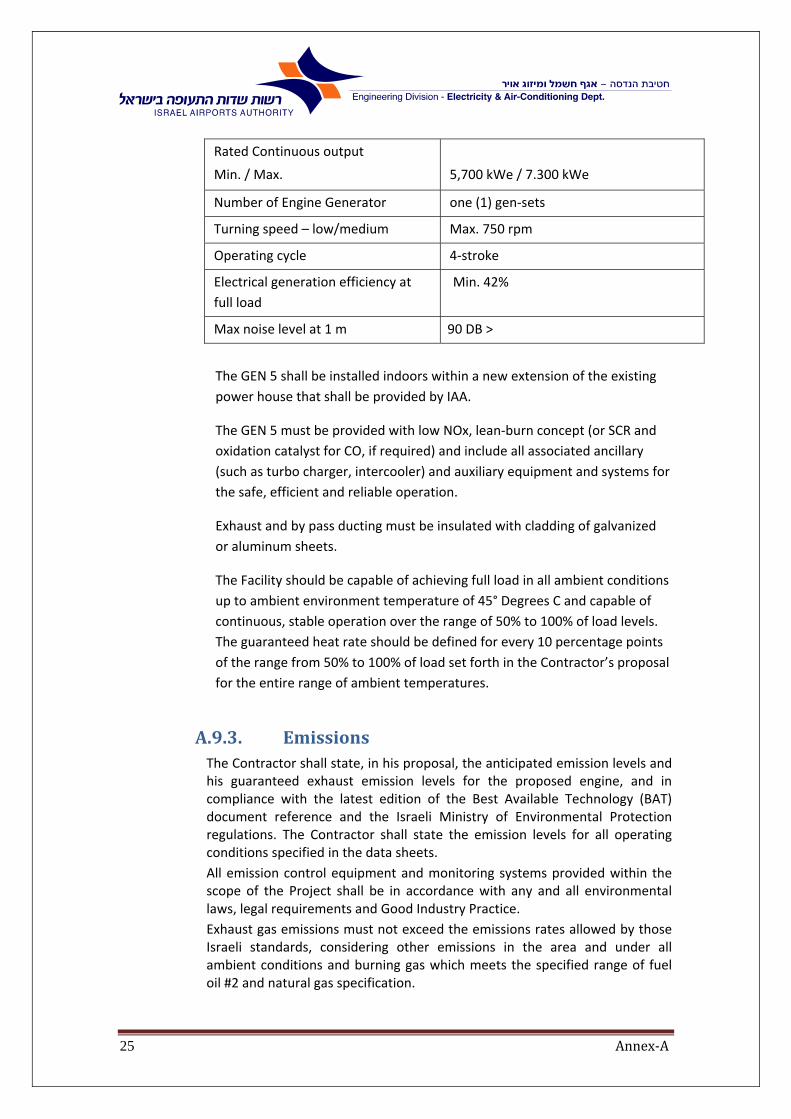
Rated Continuous output
Min. / Max.
5,700 kWe / 7.300 kWe
Number of Engine Generator one (1) gen‐sets
Turning speed – low/medium Max. 750 rpm
Operating cycle 4‐stroke
Electrical generation efficiency at
full load
Min. 42%
Max noise level at 1 m 90 DB >
The GEN 5 shall be installed indoors within a new extension of the existing
power house that shall be provided by IAA.
The GEN 5 must be provided with low NOx, lean‐burn concept (or SCR and
oxidation catalyst for CO, if required) and include all associated ancillary
(such as turbo charger, intercooler) and auxiliary equipment and systems for
the safe, efficient and reliable operation.
Exhaust and by pass ducting must be insulated with cladding of galvanized
or aluminum sheets.
The Facility should be capable of achieving full load in all ambient conditions
up to ambient environment temperature of 45° Degrees C and capable of
continuous, stable operation over the range of 50% to 100% of load levels.
The guaranteed heat rate should be defined for every 10 percentage points
of the range from 50% to 100% of load set forth in the Contractor’s proposal
for the entire range of ambient temperatures.
A.9.3. EmissionsThe Contractor shall state, in his proposal, the anticipated emission levels and his guaranteed exhaust emission levels for the proposed engine, and in compliance with the latest edition of the Best Available Technology (BAT) document reference and the Israeli Ministry of Environmental Protection regulations. The Contractor shall state the emission levels for all operating conditions specified in the data sheets.
All emission control equipment and monitoring systems provided within the scope of the Project shall be in accordance with any and all environmental laws, legal requirements and Good Industry Practice.
Exhaust gas emissions must not exceed the emissions rates allowed by those Israeli standards, considering other emissions in the area and under all ambient conditions and burning gas which meets the specified range of fuel oil #2 and natural gas specification.
Annex‐A26
A.10. StandardsandRegulationsThe design of all facilities must be to an approved internationally recognized set of standards and codes. The designs must be to an acceptable standard of professional competence and must represent a safe, efficient use of materials to produce the required facilities. The installation on Site shall be in accordance with the following standards and shall comply with the requirements of the Israeli Electrical Corporation, and all other standards and regulations enforced (applicable) in Israel: 1 Israeli law, regulation and standards for electrical equipment and
installation.
2 General specifications for building work ( The" blue book" local
regulations issued by the ministries of housing and defense).
3 Israel Airports Authority (IAA).
4 Israel Electric Company (IECo).
5 Israel Electrical Law.
6 Safety regulations (Ministry of Labor).
7 The Standard Institution of Israel (SII).
8 The regulations and recommendations for Environment Quality by
the Ministry of Environment protection.
9 OSHA ‐ Occupational Safety and Health Administration (Israeli
Standards).
10 Israeli Home Front Command regulations concerning chemical
storage.
A.10.1. ApplicableInternationalStandardIn the absence of Israeli rules, regulations and/or standards the
following standards will apply:
ABGSM TM3
ANSI C‐39‐1
ANSI/ASME B31
AS 1359
AS 2789
BS 800
BS 4999
BS 5514
DEMA
DIN 6271
DIN 6280
DIS 8528
EGSA 101P
IEC 60034/1
IEEE 587 (Standards for transient immunity)

Annex‐A27
ISO 3036/1
ISO 3046
ISO 8528
ISO 9001 (Quality control)
JEM 1359
NEMA MG1‐22
NFPA
RFI/EMI Emission: Requirements comply with FCC rules & regulations
part 15.
Class RFI/EMI susceptibility: Mill Standards ‐ STD ‐ 461B
TA LUFT
UL‐873 Temperature Indication and Regulating Equipment
UL‐916 Energy Management Systems
VDE 875
Even though some standard parameters may be quoted hereunder,
the Contractor shall comply with the requirements of the most
updated standards versions.
A.11. AbbreviationsThe following acronyms and abbreviations shall apply:
ACC Air Cooled Condenser
ACGIH American Conference of Governmental Industrial Hygienist
AGA American Gas Association
AGMA American Gear Manufacturer Association
AIS Air Insulated Switchyard
ANSI American National Standard Institute
API American Petroleum Institute
ASME American Society of Mechanical Engineers
ASTM American Society for Testing and Materials
AVR Automatic Voltage Regulator
CCTV Closed Circuit Television
CCR Central Control Room
C&I Control and Instrumentation
CPM Construction Project Manager (IAA)
CPL Continuous Partial Load

Annex‐A28
CPU Central Processing Unit
DCS Distributed Control System
DGPT Detection of Gas Pressure and Temperature
DIN Deutsches Institut fur Normung e. V.
DLN Dry Low NOx
EMI Electro Magnetic Interference
CONTRACTOR Engineering, Procurement and Construction
FAC Final Acceptance Certificate
FRP Fiberglass Reinforced Polyester
FSNL Full Speed No Load
GEN Including engine, gear box, generator and auxiliaries
GPS Global Positioning System
HP High Pressure
HV High Voltage
HVAC Heat, Ventilation and Air Conditioning
IEC International Electrotechnical Commission
IECO Israel Electric Corporation Ltd.
IEEE Institute of Electrical and Electronic Engineers
ISO International Standardization Organization
LAN Local Area Network
LP Low Pressure
LTSA Long Term Service Agreement
LV Low Voltage
MCC Motor Control Centre
MMI Man Machine Interface
MV Medium Voltage
NEMA National Electric Manufacturing Association
NFPA National Fire Protection Association

Annex‐A29
NG Natural Gas
NTP Notice to Proceed
OLTC Off‐Load Tap Changer
ONAN Oil Natural Air Natural
PAC Preliminary Acceptance Certificate
PCU Process Control Units
PRMS Pressure Reducing and Measuring Station
PVC Poly Vinyl Chloride
RTD Resistance Thermal Detector
UPS Uninterruptable Power Supply
UTP Unshielded Twisted Pair
VDI Verein Deutscher Ingenieure
XLPE CrossLinked PolyEthylene
A.12. DocumentsFormatAll required documents shall be submitted in three hard copies and computer
media as follows:
1 Data sheets in Microsoft excel 2010.
2 I/O and MMI lists in Microsoft excel 2010.
3 Work procedures descriptions in Microsoft Word 2010.
4 All drawings shall be in AutoCAD2012.
Later versions of above mentioned software packs may be used only when
permitted by IAA
A.13. LanguageAll drawings, PLC ladder descriptions, function blocks descriptions and
manuals shall be in English

Annex‐A30
A.14. TechnicaldocumentsthatwillbesubmittedtotheContractor1 Specification.
2 Single line drawings of the existing Energy center.
3 Proposed General arrangement drawings.
4 Proposed Diesel Fuel oil P&ID.
5 Proposed Lubricating system P&ID.
6 Proposed Compressed air P&ID.
7 Proposed Sludge system P&ID.
8 Proposed Layout Drawings of:
Generator's Layout and Future absorption chiller, layout‐
water condenser & chilled water pumps and piping
Generator's exhaust system layout
Indoor ventilation system
Roof mounted equipment layout
Electrical systems layout
Cooling system layout
Building construction drawings
A.15. VerificationbytheContractorDuring the bidders' tour and conference the contractors shall conduct field
verification to capture all necessary details; dimensions, structural
implications, access road, project are constructability, contractor's set up
areas and weather conditions during the project.
No future claim shall be accepted due to mismatches and construction
conflicts on site.
A.15.1. LayoutverificationduringthebidThe Contractors shall carefully study the Tender Documents, check
and approve the IAA Propose layout and Construction drawing as
specified in section A‐12. In case of any discrepancies the contractor
will notify IAA.
Contractors may propose alternative layout solutions as part of value
engineering, within the limitations and outline of the planned
structure, designed by IAA.
The contractor's alternative layout solutions shall include:
General arrangement of all major equipment to be presented on the
building layout drawings, including:
Generator's Layout and Future absorption chiller, layout‐
condenser. water & chilled water pumps and piping
Annex‐A31
Generator's exhaust system layout
Indoor ventilation system
Roof mounted equipment layout
Electrical systems layout
Cooling system layout
Day tank
Building construction drawings
IAA may approve or reject contractor’s proposals.
A.16. Contractor'sTechnicalSubmittalswithinthebidSpecifications document and technical data and schedules prepared by the
Contractor:
1 For any proposed equipment, the Contractor shall submit reference
list of similar systems and installations supplied by the contractor.
The list shall include; purchaser's name, installation location, name of
factory manufactured equipment, software supplier, system
configuration and the system's start‐up date.
2 Dedicated organizational chart for the project with key personnel,
names, tasks and experience in the following:
Hardware manufacturing
Installation Software
System Integration
3 Sub‐Contractors proposed
4 Systems and products to be approved as submittals including
catalogue cuts, prior to installation.
5 Any document required by the IEC or by the authorities for
calculations, simulations and/or approving of the generator.
6 Proposed schedule for design, manufacturing, source inspection,
factory testing, shipment, installation, integration, site testing and
commissioning of the system.
7 Approval procedures will be pending Project Manager's and system
teams.
8 The contractor to approve in writing the proposed building layout
issued by IAA, including, but not limited to; building foundation,
structural loading (DG, electrical systems, absorption chiller system).
9 Description of synchronization system, DG protection systems and
sequence of operation.
10 Schematic drawings and block diagrams detailing equipment
assemblies and indicating dimensions, weights, structural loadings,
and required clearances, method of field assembly, components,
location and size for each field connection.

Annex‐A32
11 Schematic drawings and block diagrams containing the following
information about the local PLC based control panels:
Block diagrams showing all significant pieces of equipment as
well as control devices.
Details of control panels.
12 System configuration showing peripheral devices, power and back‐up
supplies, communication networks and interconnections.
13 Overall dimensions of typical panels and switchboards to be installed
on site and all required preparation to be done before installation,
including; Penetrations and house‐ keeping pads.
14 Software packages description and sequence of operation.
15 HMI software packages description.
16 Proposed list of graphic and non‐graphic screens and windows
17 Characteristics of the communication between the central system
and the local PLCs.
18 Communication protocols and proposed standards.
19 Description of the factory tests and acceptance tests to be
performed.
20 Mandatory spare part list
21 MTBF of major equipment
22 Heat and mass balance diagram
23 One line diagram
24 Layout Drawing of the project including the boundaries of supply
25 P&I Drawing of the complete project
26 Recommended training (at manufacturer's facilities and on the Job
site)
27 Recommended service agreement

Annex‐A33
A.17. SubmittalsandShopdrawingsafterawardThe Contractor shall provide, within three months of the signed contract,
submittals and shop drawings, for review and approval in accordance with the
requirements of the contract documents. The Contractor shall be responsible
for and bear all cost of damages which may result from the ordering of
material or from proceeding with any part of the work prior to the approval of
submittals and shop drawings.
The review and approval of submittals will not be construed as:
1 Permitting any departure from the Contract requirements.
2 Relieving the Contractor of the responsibility for errors, including;
details, dimensions and materials.
3 Approving divergences from details furnished by IAA except as
otherwise specified.
The contractor shall perform and submit transient stability study showing
that the proposed Genset is capable for working in the Airport grid without
getting to any possible oscillations after short circuit on the HV or MV grid.
A.17.1. ShopDrawingsShop drawings should establish lines and levels for the work specified
and check interferences with structural, architectural and other
disciplines. If a disciplinary conflict does occur, call the attention of
the IAA or its representative for clarification in writing. Shop drawings
shall include drawings to a scale of 1:25 showing all equipment,
ductwork, piping and electrical work to be installed, including
sections and elevations. For critical areas, provide sectional drawings
to a minimum scale of 1:10.Shop drawings shall be complete, detailed
and dimensioned and shall include the following:
1 Fabrication and, layout drawings.
2 Heat and mass balance diagram
3 One line diagram
4 P&I Drawing of the complete project
5 Installation dimensions, weights & materials
6 Complete list of materials.
7 Manufacturing and installation schedules.
8 Manufacturer’s mechanical and electrical drawings.
9 Wiring and control diagrams, as applicable.
10 Catalog cuts or entire catalogs.
11 Descriptive literature.
12 Performance and test data including: Capacities, rpm, BHP,
design and operating pressures, temperatures, complete
electrical data and Electrical diagrams.
Annex‐A34
13 Structural drawings.
14 Additional requirements specified in the technical
specifications.
15 Drawings shall be A0 size (820 mm x 1188 mm). Each shop
drawing shall have a blank area 100 mm by 150 mm located
adjacent to the title block. The title block in the lower right
hand corner shall display, at least, the following:
Number and drawing title.
Date of drawing.
Revision block
Name of project.
16 Name of Contractor and sub‐Contractor submitting the
drawing.
17 Clear identification of contents and location of the work.
18 Title and number of Specifications section.
If drawings show variations from the Contract requirements
because of standard shop practice or for other reasons, the
Contractor shall describe such variations in his letter of
transmittal .
If approved, each of the shop drawings will be identified as having
received such approval. Shop drawings with required corrections
shown will be returned to the Contractor for correction and if required
will be resubmitted. Resubmitted shop drawings will be handled in the
same manner as first submittals. On resubmitted shop drawings the
Contractor shall direct specific attention, in writing or on resubmitted
shop drawings, to revisions other than the corrections requested by
the CPM on previous submittals. The Contractor shall make
corrections as directed.
When the shop drawings have been completed and signed by the
CPM, the Contractor shall proceed with construction accordingly and
shall make no further changes except when received written
instructions from the CPM.
A.17.2. DrawingidentificationschemeThe Contractor shall adopt IAA's identification format and numbering
system on his drawings.

Annex‐A35
A.18. SamplesThe Contractor shall submit samples as specified or as directed and shall be
presented to the CPM for approval. The Contractor shall prepay shipping
charges on samples. Materials or equipment shall not be used until approved
Each sample shall be labeled as follows:
1 Name of project.
2 Name of contractor and subcontractor.
3 Material or equipment represented.
4 Place of origin.
5 Name of manufacturer and model.
6 Location used in the project. Samples of finish materials shall have
additional markings identifying them under the schedules.
Product Substitutions will not be permitted unless they are approved in
writing
A.19. CertificationThe Contractor shall submit the following certificates to demonstrate proof of
compliance with requirements specified in the technical specifications for
each of the following:
1 Names of Products and materials.
2 Tests results of equipment and systems.
3 QA/QC test results of personnel, manufacturers, fabricators and
installers.
4 Test results of specific engine‐generator unit sets and auxiliaries, from
the original manufacturer and from the Contractor
Each certificate shall be signed by an official authorized to certify the specific
type of equipment on behalf of the issuing organization and shall bear the
name and address of the Contractor, the project name and location, quantity
and dates of shipment or delivery to which the certificates apply Certification
shall not be construed as relieving the Contractor from furnishing satisfactory
systems and equipment.
Certified test report:
Submit original.
Unless otherwise specified, testing shall be conducted by an
independent and recognized testing agency which certifies
that it complies with the standards in Israel.
Contractor shall provide the necessary permits from the Israeli Labor Ministry,
for operating the engine‐generator plant.

Annex‐A36
A.20. DocumentationThe Contractor shall submit to IAA the original and two copies of each test
report with name and address of testing laboratory and dates of tests to
which reports apply. The Contractor shall provide charts describing
performance of his proposed engine‐generator as a function of changing
external variables.
One such chart shall show KW output as a function of ambient combustion air
temperatures.
A.21. SubmittalsbeforefinalcompletionBefore final completion, the Contractor shall provide the CPM three sets of
record drawings and manuals and “as made drawings”. All documents shall be
completed and brought up to date, Manuals shall include the following data:
1 Table of contents.
2 Contractor’s name, address and telephone number, with similar data
for his 24‐hour service organization.
3 List of Products' with Manufacturer’s names, addresses and
telephone numbers, with similar data for their local representatives,
distributors and service agencies.
4 Catalog, model and serial number of equipment installed.
5 Description of equipment.
6 Diagrams.
7 Statement of warranty as specified.
8 Description of modification, servicing and repairs performed prior to
start of warranty.
9 Dates warranty begins and expires.
10 Manufacturer’s operating and maintenance instructions,
manufacturer’s parts list, illustrations and diagrams.
11 One copy of each wiring diagram.
12 PLC ladder diagrams with the I/O lists.
13 Software listing for the graphic displays including operator sequence
control.
14 Complete database listing documentation.
15 Troubleshooting instructions.
16 Complete and detailed list of screens and windows.
17 List of spare parts, prices and recommended stock quantities for
routine maintenance of the equipment for two years, five years and
ten years operation .Provide a list of spare parts that are considered
critical and for which long lead delivery would create unacceptable
down‐time for equipment.
18 List of Special tools required to perform inspections, adjustments,
maintenance and repairs. Special tools are those developed to
Annex‐A37
perform a unique function related to the particular equipment and
not available from commercial use.
19 Copy of each approved shop drawing of equipment and system.
A.22. Contractor'spersonnelContractor's personnel shall include all persons engaged, at the relevant time,
in the performance of the work under the contract on behalf of the
contractor, including the contractor's employees, agents, advisers,
consultants and suppliers, subcontractors and all subcontractors' employees,
agents, advisers, consultants and suppliers.
A.22.1. SkilledlaborThe contractor shall employ skilled personnel throughout the various
stages of this project. For systems’ integration, testing, calibrating,
start‐up, commissioning and training the contractor shall employ
skilled labor that are also experienced in the operating of electrical,
controls, heating, cooling, ventilation and mechanical systems.
A.22.2. ProjectManagementThe project management is part of the scope of the work of the
Contractor and includes all the usual activities of a professional
project management, including, but not limited to, the requirements
specified in this document. The Project Manager shall act as the
primary point of contact to the IAA regarding all matters relating to
the works.
Project Manager shall be, at least, a Certified Practical Electrical or
Mechanical Engineer with minimum 10 years' experience in managing
and supervising relevant work.
A.22.3. SafetysupervisorThe contractor shall engage "certified safety supervisor" that will be
submitted to the Ministry of Labor, as required by law. Safety
supervisor shall conduct all activities as required by the Israeli law.
A.22.4. TechnicalAssistanceforgeneratorandabsorptionchiller
The contractor shall engage technical advisory personnel from
generator manufacturer to provide technical assistance for all
Annex‐A38
generator activities such as: installation, integration, testing,
calibrating, start up and commissioning.
A.22.5. Local(Israeli)supportforgeneratorandchiller
The Contractor shall have local Israeli representative and shall be able
to provide solutions and react promptly to problems arising, as per
contract agreement.
A.22.6. UseofSubcontractors1 If the contractor wishes to use subcontractors, he must present
comprehensive details about each subcontractor and the
subcontractors’ scope together with the quotation to the IAA's
approval.
2 The contractor must not use any additional subcontractors
without IAA’s written approval once the contract is signed.
3 The contractor acknowledges that IAA’s approval of any
subcontractor does not relieve the contractor from any
requirement as defined in this specification or under elsewhere
defined in the contract. The approval from IAA does not confirm
or acknowledges the suitability of a subcontractor in any shape or
form. In any case the contractor is fully responsible for the
subcontractors work, performance and schedule. The point of
contact with subcontracted work remains with the contractor.
IAA is not obligated to discuss or even negotiate with
subcontractors.

Annex‐A39
A.23. TrainingThe contractor shall provide at the manufacturer's facilities (generator,
absorption chiller) a full comprehensive training required to perform all tasks
for preventative maintenance services and corrective maintenance. During
the bid period the contractor will submit the training program for review and
approval by IAA.
Training and manuals shall be in English.
A.23.1. GeneratorTrainingshallincludeasfollows:The generator training will be divided into two rounds at different
time periods, as follow:
1 Two weeks training at the manufacturer’s facilities. Without
additional cost to the IAA (except for flights and hotel
expenses for the IAA's representatives which will be borne by
the IAA. The training shall include all levels of corrective and
preventative maintenance (including full overhaul). The
purpose for this training is for the manufacturer to provide
Technician's qualification for repair and full maintenance of
the system. System shall include, but not limited to:
Safety procedures
NG safety procedures
General acquaintance with all system equipment and
component.
Review the Operational and Maintenance manuals
supplied
Operation of all equipment in all modes of operation.
Maintenance procedures.
Components / System calibration
Troubleshooting procedures
Practical training
Technician training will include "train the trainer
Qualification certificate will be issued by the manufacturer to
technicians successfully completing the training.
2 Two sessions of one week training, each at the IAA's facilities,
under real operating conditions. Systems shall include, but not
limited to:
Safety procedures
NG safety procedures
General acquaintance with all system equipment and
component.

Annex‐A40
Operation of all equipment in all modes of operation.
Components / System calibration
Electrical switchboard and transformers operation and
maintenance
Troubleshooting procedures
Additional two weeks training at the manufacturer’s
facilities or one week training at the IAA’s facilities
may be required for additional cost
A.23.2. AbsorptionLiquidChillerstrainingThe Contractor shall furnish a competent engineer to instruct and
train IAA's designated personnel in the operation and maintenance of
every part, device and piece of equipment of the Absorption Chillers,
with emphasis on proper startup and shut ‐down procedures,
preventive maintenance and lubrication procedures with
recommended lubricants, overhaul and maintenance methods,
adjustment and calibration of instruments and controls, the use of
special tools and safe practices. One engineer and three foremen
shall be trained for a period of two (2 weeks).

Annex‐A41
A.24. WarrantyandMaintenanceServices
A.24.1. GeneralThe Contractor shall provide warranty, support and maintenance
services for the Plant, in accordance with the service levels that are
specified below (SLA) and the provisions of the Contract.
The Contractor shall include the following lists in its proposal to the
Tender:
(a) List including prices of all Spare Parts, Special Tools, Consumables
and costs of supervision by Contractor's representative that are
required, according to Contractor's O&M Manual and in
accordance with prudent industry practices, for all Preventative
Maintenance (as defined below) up to and including full overhaul.
The Contractor shall include a breakdown of all parts that are
required for each Preventative Maintenance service and whether
such service requires supervision by the Contractor.
(b) A full list of all Spare Parts, Special Tools and Consumables
required for the proper operation of the Plant according to the
Guaranteed Availability. In this list the Contractor shall specify the
recommended Spare Parts, Special Tools and Consumables with
respect to the Warranty Period, the Technical Support Period and
Maintenance Period.
The above lists shall be evaluated as part of Contractor's proposal to
the Tender and shall bind the Contractor.

Annex‐A42
A.24.2. DefinitionsThe following terms shall have the meaning set forth below when
used in these Technical Specifications:
"Hotline" means a remote service provided by the Contractor via phone (telephone support) as a response to a call placed by the IAA in the event of malfunctions and/or any other problems discovered. The Hotline service may result the commencement of the Remote Support or the dispatch of a technician to the site, as further detailed in section A.24.6.
“Outage” means removal of the Plant from electric and thermal power generation service and/or planned downtime for Preventative Maintenance.
“Planned Maintenance”
means, with respect to the Plant, the following: (a) Any major overhaul, periodic inspection,
testing, repair, and/or replacement of components of the Plant, as specified in the supplier O&M manual , as reasonably necessary in light of deterioration due to normal wear and tear on the Plant and as required in accordance with the generator supplier O&M manual to ensure continuous and reliable operation of the Plant.
(b) the repair and/or replacement of components and parts of the Plant subject to maintenance set out in paragraph (a) above, (1) the need for which is found during any Planned Maintenance Outage and (2) which is reasonably determined to be necessary prior to the next scheduled Planned Maintenance Outage to continue safe operation in each case in accordance with Prudent Industry Practices;
"Preventative Maintenance"
Means both Planned Maintenance and Routine Maintenance.
“Prudent Industry Practices”
Means the exercise of that degree of skill and diligence, and of such practices, methods and acts, at a minimum as would ordinarily be expected in the power generation industry from a prudent owner and/or operator acting lawfully, reliably and safely in connection with power generation facilities and equipment similar to the Plant.
"Remote Support"
Means the remote service, provided by the Contractor, by using additional available skilled personnel, with computer remote facilities to log into the systems located at Ben Gurion Airport, for providing additional support and/or failure repair.

Annex‐A43
“Routine Maintenance”
Means maintenance of a regular, preventive or minor nature that is performed periodically, during Plant shutdown or during operation, to maintain equipment in working order on a day‐to‐day basis without the need for an Outage, including, but not limited to, maintenance of the Spare Unit in accordance with O&M manual, inspection, lubrication, calibration, adjustment, minor leak repair, provision of fluids, greases, and resins, cleaning and replacement of operational spares, filters, strainers and cartridges, maintenance or replacement of sensors, fuses, thermocouples, gauges, switches, and light bulbs, and other similar preventive, painting, corrosion prevention of minor nature, heating and air‐conditioning units, routine or minor work.
“Unplanned Maintenance” or "Corrective Maintenance"
Means maintenance of the Plant that is required to remedy an in‐service failure or abnormality of a component, whether discovered during an Outage which occurs as a result of a problem or failure of the Plant, or during inspection or monitoring of the Plant. Unplanned or Corrective maintenance shall include all measures required to rectify or repair the defect, including diagnostics, all kind of mechanical, electrical or software works, removal of a defective part and installation of a replacement part, testing, calibration and adjustment of the equipment as necessitated by a repair or replacement.
Mandatory Spare Parts
“Mandatory Spare Parts” means parts and components for the Plant which Owner must keep and maintain at the Site during the term of this service more specifically will be identified in suppliers proposal

Annex‐A44
A.24.3. WarrantyperiodforPhase‐1.
The contractor shall provide Warranty for the engine Generator itself
and any auxiliary system that are in used for Phase one of the project,
installation works and all interfaces.
Warranty Period shall be for a period of 24 months after final
commissioning under max load conditions and as of the date of
issuance of the Final Acceptance Certificate for the Generator
A.24.4. WarrantyperiodforPhase‐2The contractor shall provide Warranty for the Gas system of the
Generator for a period of 24 months after final commissioning of
Phase 2 under max load conditions and as of the date of issuance of
the Final Acceptance Certificate for the Generator
A.24.5. Warrantyperiodforphase3The Contractor shall also provide warranty period for the third phase
of the Project for 24 months as of the date of issuance of the Final
Acceptance Certificate for the Absorption Chiller. Warranty period for
phase 3 shall include warranty for the Absorption Chiller and any
auxiliary systems, installation works and interfaces.

Annex‐A45
A.24.6. ServicesduringWarrantyPeriod
Services during the Warranty Period will be carried out by the
contractor, without costs to the IAA. The Contractor will be
responsible to maintain skilled and trained staff available for
remedying any defects and/or performing all maintenance at all‐
times throughout the Warranty Period.
As part of the Warranty for phase 1 and phase 2, the Contractor shall
be responsible for performing Corrective Maintenance services. All
Preventative Maintenance services for the Generator during the
Warranty Period will be carried out by the qualified IAA personnel. A
representative of the contractor will be required to be present for
those services which the contractor has listed on its Proposal as
services that its actual presence on site for supervision are required.
During Warranty Period for phase 3, the Contractor shall be
responsible for performing full Preventive Maintenance and
Corrective Maintenance services.
The scope of services to be provided by the Contractor during
Warranty Period, including with respect to major overhauls, shall be
as specified in Contractor's proposal to the Tender, and in any event
not less than the minimum requirements specified in these Technical
Specifications. All works shall be coordinated with the IAA.
As part of the Services the Contractor shall provide a Hotline service
24 hours a day 365 days a year for on‐going telephone support
service.
The Contractor shall provide contact details including phone and fax
numbers and e‐mail through which it will provide the Hotline.
Level 1‐ online trouble shooting: an engineer on behalf of the
Contractor will register all relevant information (incident description,
error message etc.) given by the IAA's representative using a report in
the form acceptable to the IAA.
Such information will be analyzed by the engineer, which shall
provide an answer/procedure to the IAA's representative in order to
solve the defect within the day.
In addition to the telephone support services the IAA shall have an
option to order services of repair through Remote Support. If the IAA
decides to exercise such option, at its sole discretion, the Contractor
shall provide the IAA with such services as specified herein.

Annex‐A46
Level 2 ‐ on‐site support: In case the incident is not solved by the
assistance of Level 1 and/or due to any other urgent necessity (e.g.
mechanical brake down or other justified reason) that will require
immediate intervention, the Contractor will send on‐site support of
an engineer or an expert technician and will take all necessary actions
including all necessary tests in order to repair the defect.
In case equipment is needed in order to repair the defect, the
Contractor will take all measures in order to transport and deliver
such equipment without any delay, using air express transportation if
needed and will use all means in order to repair the defect as soon as
possible.
A.24.7. SpareParts,SpecialToolsandConsumablesDuring Warranty Period the Contractor shall be responsible for the
supply of any and all Spare Parts and Consumables (except for the
fuel/natural gas), as may be required for the operation of the
generator according to the guaranteed availability, at its sole
expense. The contractor shall also supply at its expense a complete
set of special tools that are required for performing all the
maintenance services during the Warranty Period.
Upon signing of the Contract, the IAA shall purchase first batch of
Spare Parts which will include any Spare Parts, Special Tools and
Consumables as the IAA may decide to purchase, based on the list of
recommended Spare Parts that was provided by the Contractor.
Should the Contractor use any of these Spare Parts during Warranty
Period, it shall immediately resupply such part at its expense.
At any time during the Contract Period the IAA shall have the option
to purchase from the Contractor Spare Parts, Special Tools and
Consumables, in quantities as may be determined by the IAA, at its
sole discretion, as specified in the Contract.
A.24.8. ResponsetimeandSLALiquidatedDamages
The contractor shall respond to IAA telephone call within maximum 1
hour. In case on‐site support is required, a skilled representative of
the Contractor shall arrive on site within no later than 48 hours from
the telephone call.

Annex‐A47
Correction time of any defect or malfunction shall not exceed 8
working days.
In the event of failure by the Contractor to comply with the SLA, the
Contractor shall pay a penalty according to the following:
Between 8 ‐15 working days – 2,000 Euro per each day of delay.
Between 15 ‐90 working days – 2,500 Euro per each day of delay
More than 90 working days delay shall be considered material breach
of contract.
A.24.9. ServiceafterWarrantyPeriod(LTSA)
A.24.9.1. TechnicalSupportPeriodFollowing the Warranty Period for phase 1, the Contractor shall
continue to provide the IAA with technical support services for a
period of 120 months (the "Initial Technical Support Period"). The
IAA shall be entitled, at its sole discretion, to extend the Initial
Technical Support for additional periods, which in the aggregate
shall not exceed 15 years (together, the "Technical Support
Period").
During the Technical Support Period, the Contractor shall provide
the Hotline support services as specified above. In the event that
the incident is not solved by the assistance of Level 1, the IAA shall
be entitled to purchase from the Contractor on‐site support of an
engineer or an expert technician, as specified in the Contract.
In case on‐site support is required, a skilled representative of the
Contractor shall arrive on site within no later than 8 days from the
telephone call.
In the event of failure by the Contractor to comply with the SLA,
the Contractor shall pay a penalty according to the following:
Above the 8 working days – 2,000 Euro per each day of delay.
A.24.9.2. MaintenancePeriodFollowing Warranty Period for phase 3, the Contractor shall
provide the IAA with the same Preventative Maintenance and
Corrective Maintenance services as provided during the Warranty
Period for phase 3, as of the end of the Warranty Period and until

Annex‐A48
the end of the Technical Support Period (the "Maintenance
Period"). Services during Maintenance Period shall include the
supply of all Spare Parts, Consumables and Special Tools, at the
Contractor's expense.

Annex‐A49
B. ChapterB‐EquipmentNumberingSystem
B.1. Objectives1 Enable computerized tracking of the equipment inventory, maintenance
and operation
2 Referencing the equipment to main/sub group it belongs to
3 Identifying the location of the equipment
4 Identifying a unique ID number for each item
B.2. NumberingScheme1 Equipment Numbering (TAGS):
All materials shall be marked for construction with identification
numbers which correspond with the part numbers on the appropriate
drawings of the contract works. The Contractor shall follow the Energy
Center equipment numbering system, but he may also propose his
standard numbering system for IAA approval.
2 Conduits and cable numbering:
Conduits will not be tagged but will be color coded on the drawings,
according to the Israeli Standard including directional arrows.
3 Cables: Cables will be tagged by an eight character identification
number composed of the following elements:
The first three characters: are defined the cable type‐ HV cable,
LV cable, control cable, etc.
The next three characters: are defined according to the cubicle
number from which the cable origins from.
The last two characters: are digits of the sequential number of
cables in this cubicle.
4 In the event the cable route extends outside the perimeters of the
building where the feeding equipment is located, the cable will be
tagged by an additional tag (eight characters) which identifies the
equipment to which it is hooked to.

Annex‐A50
B.3. MarkingandLabelingThe contractor shall ensure identification of all components, including: wires,
cables, conduits, junction boxes, motors, control devices, etc.
Labels shall be in Alphanumeric English in capital letters and in Hebrew,
according to IAA’s numbering system.
Lettering will be engraved, painted, or printed with unfading materials.
Labels shall be adhesive and fastened by means of screws or shrinkable
sleeves which will keep the labels from falling or dislodged from their
location.
B.4. SwitchboardLabeling1. Each switchboard shall be labeled by a 200x100mm, engraved
“Lamecoid Plates" denoting its name both in English and Hebrew along with a full tag number.
2. Each cubicle (for switchboard longer than a single cubicle) shall be labeled by a 50x100mm, engraved with Lamecoid Plates" denoting it's full tag number. The same label shall be installed on the back access door to the same cubicle, if exists
3. Each equipment component installed in the switchboard shall be marked with a 50x20mm “Lamecoid Plates” in black letters on a white background. The markings shall be connected to fixed parts (not onto plastic cable duct covers or likewise).
4. Each control or power conductor shall be marked at both ends by plastic strips with printed markings, denoting the specific terminal number to which the wire is connected (terminal numbers on equipment pieces or terminal number on terminal strips), as well as the cables original source and destination.
5. Each individual terminal shall be marked by up to six digits (in two groups). Each logical group of terminals (e.g. one typical motor starter) shall be identified by an additional group label. All terminal identification materials and auxiliary equipment, such as marker holders, terminal protection cover, bridges etc., shall be of the same make as the terminals. Substitute materials will not be permitted and accepted.
6. Main circuit breaker or trip push‐buttons of each switchboard shall be marked by 50x100mm red letters on a white background, engraved with “Lamecoid Plates".

Annex‐A51
B.5. CableLabeling1. Each control or power conductor shall be marked at both ends by
plastic tags with printed markings denoting the specific terminal number to which the wire is connected (terminal numbers on equipment pieces or terminal number in terminal strip), as well as the cables source connecting point. The label needs to be threaded or otherwise strongly connected to the cable or wire.
2. Each individual terminal shall be marked by up to six digits (in two groups). Each logical group of terminals (e.g. one typical motor starter) shall be identified by an additional group label. All terminal identification materials and auxiliary equipment, such as marker holders, terminal protection cover, bridges etc., shall be of the same make as the terminals. Substitute materials will not be permitted and accepted.
3. Underground cables or conduit routes shall be marked with a galvanized 2 Inchpipe, 80cm above the ground level, embedded in a 30x30cm concrete cubicle installed in the center of the route, painted with red and white (horizontal/ vertical) stripes (each stripe 20cm wide). The markers shall be installed on each bend and on straight lines at a maximum distance of 50 meters apart.
B.6. AuxiliaryEquipmentLabeling1. Junction‐boxes shall be marked twice, once on the cover and once
inside the box by 50x20mm “Lamecoid” labels. 2. Socket‐outlets, light switches, push buttons etc., shall be marked by a
25x8mm “Lamecoid ” label (black on white)denoting the circuit and switchboard number of each item. The label shall be firmed to the wall by two screws.
3. Poles shall be identified by tag numbers and circuit numbers, using 40mm dye (letters) and painting them with a contrasting color on the pole, 1 meter above ground level with permanent materials.
B.7. ConduitIdentification1. A conduit identification system shall be applied using color strips
around the conduits. These color strips shall preferably be of an adhesive plastic material suitable for the surface temperature of the conduits or insulation as well as for the prevailing in ambient conditions.
2. Flow directional arrows and identification inscription shall preferably be of the same material sand shall be provided in visible places as well as at the inlet branch connections and downstream of each valve.
3. Where plastic adhesive material cannot be applied, pipe identification has to be carried out by painting.
4. The contractor shall propose a piping identification system, subject to approval by the IAA.

Annex‐A52
C. ChapterC‐GeneratorTechnicalSpecification
C.1. General
C.1.1. GeneralDesign1. The proposed Genset will be in the range of 5,700kW to 7,300kW of net
capacity at continuous operation and shall comply with the following characteristic:
Number of Engine Generator one (1) gen‐sets
Turning speed – low/medium Max. 750 rpm
Direct Axis Synchronous Reactance [pu]
Xd” saturated
no less than 0.16.5pu
2. The generator shall be synchronous 11,000 volt, 3‐phase, 50 cycle, and skid mounted bracket type designed for direct connection to the engine flywheel.
3. The generator shall be mounted on the engine skid and arranged for easy adjustment and alignment. Provisions shall be made to enable the generator removal without disturbing the engine or the removal of other equipment.
4. The full‐load continuous‐rated kilowatt capacity of the generator shall be computed at 0.80 power factor, at the nominal speed and voltage and shall not be less than the continuously rated BHP of the engine multiplied by 0.746 at the full‐load generator efficiency (less 0.01 wind, friction and exciter losses).
5. Capable of carrying 110% of the load for 2 hours out of any 24‐hour period
6. The generator shall be capable of carrying a momentary overload of 250% of the normal ampere rating without causing any damage with the field current set for rated load excitation. The grounding resistor of the generator shall suit this condition as well as protective relays' setting.
7. Under full‐load conditions, the temperature rise of the stator shall not
exceed 105C, by RTD measurement, in accordance with AIEE standards
based upon an ambient temperature inside the room, calculated at 40C.
8. The generator voltage regulation system shall be a three phase sensing
solid state Volts‐per‐Hertz type, providing voltage regulation within 1%.
The generator voltage regulation shall not exceed 25% where the load is reduced from full load to zero when the generator is operating at rated voltage and power factor.
Annex‐A53
9. According to IEC requirements and regulations, the contractor is required to perform a study confirming the GENSET capability to remain stable following a specific disturbance occur at the connection point to 161kV NATIONAL GRID, considering any pre‐fault working point of "P‐Q CAPABILITY CURVE".
The specific disturbance is:
o Bolted Three Phase short circuit eliminated in first Zone of system's protections (up to 100msec)
o From "Transient stability" point of view, the "critical time" of the GENSET must be at least 180 msec.
10. In addition to the individual data of the GENSET components, the contractor shall provide the following data:
o Full Moments of Inertia "J" for the full machine, including engine, flywheel, coupling and alternator in [ Kgm2]
o Total Inertia Constant "H" (Generator, Prime mover, etc.) in [MWs/MVA]
Power System Stabilizer (PSS) shall be included to improve the damping of possible oscillations in the HV and MV networks by adding a signal to the voltage regulator of the excitation system .
11. Damper windings shall be provided to eliminate all tendencies to hunt, due to pulsating torque characteristics of the diesel engine, to assure the best parallel operation.
12. The insulation of the field and armature of the generator shall be of Class "F" classification in accordance with the latest AIEE standards.
13. The stator shall be equipped with six embedded temperature detectors of the 100 ohm resistance coil type. Temperature indication shall be provided on the local control panel as well as on the main operator workstation (from the local PLC via communication system).
14. The generator cooling shall be by air‐water radiators, installed on the roof of the generators building, provided by the contractor.
15. A space heater of a proper capacity shall be furnished for the generator stator winding compartment to prevent condensation from forming. The space heater shall be controlled by local PLC. The space heater will be activated during stand‐by mode of the generator.
16. The design of the generator, together with its exciter, shall be such that a generator field rheostat will not be necessary.
17. A neutral grounding resistor shall be sized to limit the bolted line‐to‐ground fault current at the generator terminals, to the three‐phase line‐to‐line fault current. This should be checked to meet installation requirements.
18. The "GEN" (Including engine, gear box, generator and auxiliaries) shall have the standard AIEE tests before shipment from the factory. The test results shall be provided.
19. All constructions shall conform to the NEMA or International Electrical Commission standards.
20. The generator output shall have a wave form deviation of less than 5%, with a TIF factor less than 50 and a THD factor less than 3%.

Annex‐A54
21. The generator and its excitation system shall be able to operate within voltage limits providing full rated generating power.
22. The exciter shall be rotary brushless design with a permanent magnet alternator as a source of excitation power. The exciter shall be direct driven.
23. The exciter temperature rise shall not exceed 105C, by RTD measurement, in accordance with AIEE standards based upon an
ambient temperature of 40

Annex‐A55
C.1.2. EmissionsandNoiseLevelsPollutants emissions shall be in compliance with the latest edition of
the Best Available Technology (BAT) document reference and the
Israeli Ministry of Environmental Protection regulations and comply
with the latest German TA‐Luft 2002 standards for emissions
requirements, when operating at full nominal load. There are no
specific requirements for transient start‐up and shut down
operations.
Exhaust gas emissions must not exceed the emissions rates allowed
by the Israeli standards, considering other emissions in the area and
under all ambient conditions and burning fuels which meets the
specified range of liquid fuel or gas fuel specification. The following
table presents the emission limit values standards.
1‐ DSCM: Dry Standard Cubic Meter, 0 0C, 1atm @5%O2.
C.1.3. NoiseLevelsThe engine supplied will contribute to the noise level within the operating
space in the EC building, see annex C appendix A.
Pollutants
Limit Value
T.A.Luft2002
SOx(mg/DSCM1) ‐‐‐
NOx(mg/DSCM1) 500 (Liquid Fuel)
250 (other, 4‐stroke Otto Engine)
(No standard under 300 operating hours)
PM(mg/DSCM1) 20 (Liquid Fuel continuous)_
80 (Liquid under 300 operating hours)
No limits (Natural Gas Fuel)
CO(mg/DSCM1) 300
(No standard under 300 operating hours)
NH3(mg/DSCM1) 30
TOC(mg/DSCM1) ‐‐‐
Formaldehyde(mg/DSCM1) 60
Annex‐A56
C.1.4. VibrationsMaximum vibrations permitted shall be as follows (1‐order, peak‐to‐peak values, firmly mounted):
1. 0.15 mm/s RMS horizontal
2. 0.15 mm/s RMS vertic
C.2. AvailabilityandReliabilityThe station must be designed to achieve the levels of availability and reliability
normally expected for modern power plants. It is expected that the Facility
will operate on a variable mode of plant loading based on economic basis. The
expected average equivalent availability, for the lifetime of the facility will be
equivalent to, or greater than 92% for the first year following the commercial
operation date and 95% thereafter.
C.3. MaintenanceAccessConsideration will be given for easy accessibility, as per code, to all systems
and components for maintenance needs and operational requirements, when
designing the layout of the equipment package. Access will be provided to all
equipment and any areas requiring maintenance. The equipment shall be
designed so that all maintenance can be carried out with the minimum of
special facilities or tools.
All equipment and piping will be neatly placed and carefully arranged on the
skid, where it is possible to ensure that they do not obstruct maintenance
operations. The successful contractor shall work closely with the CPM& IAA
management to ensure that the most effective layout is applied, and
adequate access for maintenance is achieved effectively within the facility.
Annex‐A57
C.4. MechanicalDesignThe engine design shall be such that the engine will be capable to develop full rated horsepower operating, as a dual fuel (diesel fuel oil and natural gas) engine. The engine shall supply the rating and speed which it was designed for.
The engine shall be, V‐ (Vee) or L‐ (inline configuration), turbocharged mechanically injected, dual‐fuel engine. The engine and generator shall be mounted on a common base frame that also includes a lube oil pump for engine lubrication in addition to other accessories.
In emergency mode, the engine shall be capable of starting with the use of compressed air, pre‐lube and fuel oil prime functions, and with only 24 VDC control voltage available.
The engine design shall be such that, together with its driven equipment, critical speeds will not appear within the normal operating ranges.
The nominal rotation speed of the engine shall be 750 RPM or lower.
The engine will be designed to be four (4) stroke.
The maximum exhaust back pressure of the engine shall not exceed 6.7 kPa at full rated continuous load.
The engine design shall permit using diesel fuel oil for pilot ignition while running on natural gas. The dual fuel engine design shall be able to allow changing from diesel fuel oil to natural gas (or vice versa) while running without surging or significantly affecting the speed or load carried by the engine.
The proposed engine should be designed for the minimum amount of residual unbalance. The contractor shall furnish with his proposal primary and secondary unbalanced forces and couples for the engine being offered.
The engine and the generator shall be assembled on a common base by the engine‐generator manufacturer. The base will be designed and built to resist deflections, maintain alignment and minimize linear resonant vibrations. The diesel generator sets shall be provided with mobile type spring vibration isolators. The anchor bolts shall be supplied complete with the diesel generator sets.
Ignition of the fuel or air charge, when operating in the dual fuel or diesel oil modes, will be by heat of compression. In the dual fuel mode, ignition shall be by pilot fuel oil supplied by direct injection into the cylinder.
The diesel generator will reach, in normal procedure, nominal operating speed and voltage and at least 1/3 of its full load capacity within 60 seconds, or less, after receiving a start signal when kept warm as described herein. Full
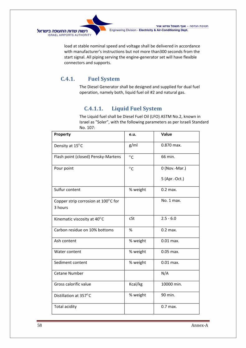
Annex‐A58
load at stable nominal speed and voltage shall be delivered in accordance with manufacturer’s instructions but not more than300 seconds from the start signal. All piping serving the engine‐generator set will have flexible connectors and supports.
C.4.1. FuelSystemThe Diesel Generator shall be designed and supplied for dual fuel operation, namely both, liquid fuel oil #2 and natural gas.
C.4.1.1. LiquidFuelSystemThe Liquid fuel shall be Diesel Fuel Oil (LFO) ASTM No.2, known in Israel as "Soler", with the following parameters as per Israeli Standard No. 107:
Property e.u. Value
Density at 15C g/ml 0.870 max.
Flash point (closed) Pensky‐Martens C 66 min.
Pour point C 0 (Nov.‐Mar.)
5 (Apr.‐Oct.)
Sulfur content % weight 0.2 max.
Copper strip corrosion at 100C for 3 hours
No. 1 max.
Kinematic viscosity at 40C cSt 2.5 ‐ 6.0
Carbon residue on 10% bottoms % 0.2 max.
Ash content % weight 0.01 max.
Water content % weight 0.05 max.
Sediment content % weight 0.01 max.
Cetane Number N/A
Gross calorific value Kcal/kg 10000 min.
Distillation at 357C % weight 90 min.
Total acidity 0.7 max.
Annex‐A59
To enable the operation with the liquid fuel, the diesel generator set shall be provided with a day tank with a total capacity of 10 m3 and will be installed at ground level and will be positioned outside the building, near the engine. See IAA chapter C appendix I for contractor approval or the contractor may offer alternative as part of value engineering during the bid. The contractor design shall include but will not be limited to:
A. Tank dimensions
B. Concrete containment enclosure (in which tank will be installed at
C. Pipe connections
D. Valves and counters
The tank shall be connected by means of a manually operated valve to enable maintenance work on the tank.
Tank shall have threaded pipe connections, float switch, fuel analog gauge (flag type), high‐high level, high level low level and low‐low level alarm contacts wired to a local PLC. The local PLC shall transfer signals to the Main Utilities PLC through I/O system, controlling fuel pumps operation for tank refilling the same signal will operate an air operated valve, the air to the valve will pass via a pilot operated mechanical floating system. A mechanical float shutoff valve and a manual shutoff valve on the engine supply line and a drain valve will also be included.
As on option: the contractor shall offer supply of additional day tank at capacity of 10m3 that will be connected to the existing LFO system and will be replace the old daily tank that shall be remove from the site by the contractor.
The design of this option shall be based on the existing design system the two tanks will be in the same and will be interchangeable.
The diesel fuel oil injection system shall be pump‐timed type with the amount of fuel being controlled by the governor. The fuel pump(s) shall be attached as an integral part of the engine.
Fuel injection system shall be designed with injection nozzles and fuel oil lines for each cylinder. Fuel injection nozzles shall be liquid‐cooled (kept warm when the engine is not running) with jacket water as the coolant. Isolating valves shall be provided to allow for the removal of any injection nozzle without drainage of coolant.
A heat exchanger for return fuel cooling shall be supplied, mounted nearby the diesel generator and connected to the cooling water system as described here. The diesel generator contractor will accomplish cooling loop including piping, control and measuring devices as required. The fuel excess shall be returned to the day tank passing the heat exchanger.
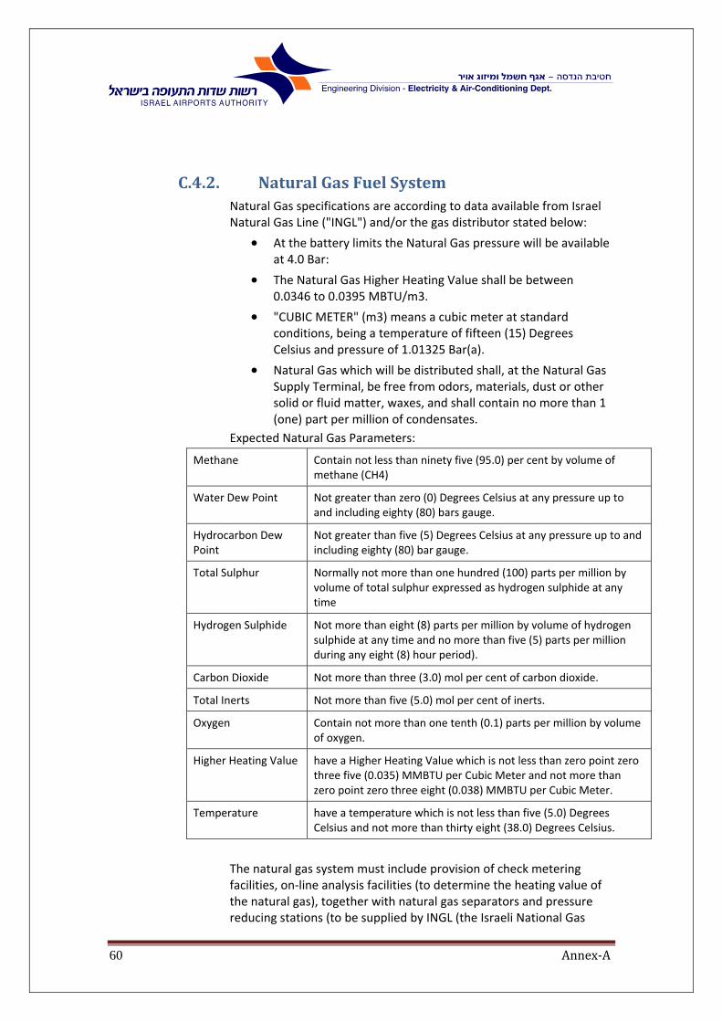
Annex‐A60
C.4.2. NaturalGasFuelSystemNatural Gas specifications are according to data available from Israel Natural Gas Line ("INGL") and/or the gas distributor stated below:
At the battery limits the Natural Gas pressure will be available at 4.0 Bar:
The Natural Gas Higher Heating Value shall be between 0.0346 to 0.0395 MBTU/m3.
"CUBIC METER" (m3) means a cubic meter at standard conditions, being a temperature of fifteen (15) Degrees Celsius and pressure of 1.01325 Bar(a).
Natural Gas which will be distributed shall, at the Natural Gas Supply Terminal, be free from odors, materials, dust or other solid or fluid matter, waxes, and shall contain no more than 1 (one) part per million of condensates.
Expected Natural Gas Parameters:
Methane Contain not less than ninety five (95.0) per cent by volume of methane (CH4)
Water Dew Point Not greater than zero (0) Degrees Celsius at any pressure up to and including eighty (80) bars gauge.
Hydrocarbon Dew Point
Not greater than five (5) Degrees Celsius at any pressure up to and including eighty (80) bar gauge.
Total Sulphur Normally not more than one hundred (100) parts per million by volume of total sulphur expressed as hydrogen sulphide at any time
Hydrogen Sulphide Not more than eight (8) parts per million by volume of hydrogen sulphide at any time and no more than five (5) parts per million during any eight (8) hour period).
Carbon Dioxide Not more than three (3.0) mol per cent of carbon dioxide.
Total Inerts Not more than five (5.0) mol per cent of inerts.
Oxygen Contain not more than one tenth (0.1) parts per million by volume of oxygen.
Higher Heating Value have a Higher Heating Value which is not less than zero point zero three five (0.035) MMBTU per Cubic Meter and not more than zero point zero three eight (0.038) MMBTU per Cubic Meter.
Temperature have a temperature which is not less than five (5.0) Degrees Celsius and not more than thirty eight (38.0) Degrees Celsius.
The natural gas system must include provision of check metering facilities, on‐line analysis facilities (to determine the heating value of the natural gas), together with natural gas separators and pressure reducing stations (to be supplied by INGL (the Israeli National Gas

Annex‐A61
Transportation Company). Natural gas piping and systems shall comply with the Israeli standards, and to be designed in accordance with Israel Natural Gas Company and Israeli Nat. Gas authority requirements.
The generator engine will be supplied and installed with all the necessary accessory devices needed for operation in gas.
The contractor shall provide documents and detail drawings for gas operation and will include the following but will not be limited to:
A. Gas pressure at the engine;
B. Detail drawing for the gas system (pipe, valves, safety valves, measuring device and all other accessories required);
C. Connection point inside/ outside the building to the gas supplier;
D. List of input data that will be connected to the PLC and to the fire alerts system;
E. Safety protection against gas leaks;
F. Special tools;
G. Safety regulation
The Contractor shall include within its scope of supply, an electrical heater with heating capability of 30 up to 500C, to allow a smooth and continuous operation of the plant during the deviation from specification of the natural gas, mainly in hydrocarbons and water content (about two weeks per year, due to the maintenance works of the natural gas supplier). The heating equipment is in addition to the INGL heating system with heating capability of up to 300C.

Annex‐A62
C.4.3. ExhaustSystemThe contractor will furnish an exhaust silencer for the diesel generator set. The silencer equipment shall have capacities as recommended by the engine manufacturer and shall reduce noise to the level required by environmental regulations.
The exhaust silencer shall be of the industrial grade incorporating a flanged inlet and outlet.
The silencer shall be from welded steel construction suitable for
engine exhaust up to 700C. The unit shall be a chamber type. All internal tubes shall be perforated and inner liners shall be provided in each chamber to ensure the industrial level of sound attenuation.
The exhaust silencer shall be equipped with hand holes in each compartment, explosion relief covers and a drain valve.
The exhaust silencer shall be supported on suitable fabricated galvanized steel supports for mounting on a concrete pad. Support dampers and springs shall be included where necessary to isolate vibration.
The silencer shall have a minimum dynamic insertion loss of 25 decibels over octave band center frequencies ranging from 63 to 8,000 Hz. Pressure loss through the silencer at the exhaust gas flow rate will not exceed 7 inches WG.
Each engine cylinder and each part of exhaust system shall be equipped with thermocouples for exhaust gas temperature measurements.
All necessary heat wrapped elbows, flexible exhaust connectors and expanders shall be provided. Piping will be self‐supported and braced to prevent any weight or thermal growths from being transferred to the engine. Flexible expansion fittings shall be provided to accommodate thermal growth. Piping supports shall be provided where necessary.
Exhaust piping shall have appropriate thermal insulation with galvanized steel cover preventing occasional contact with hot pipe.
On the exhaust system outlet an exhaust gas temperature measuring device shall be installed including local scale as well as 4‐20 mA temperature transducer for temperature reading by local PLC.
A 30 meter height self‐supporting stack with a silencer shall be supplied and installed by the contractor for the diesel generator set. The stack structure will be made of at least 10 mm thick anti‐corrosive treated steel with heat resistant painted, and will be stable suitable to withstand wind forces, damped to prevent stress, and sufficiently durable to endure metal “fatigue”. Welded inside of it, will be rod ladder stairs to reach the top. External exhaust piping and silencers shall have thermal insulation of at least 10 cm in thickness, covered with stainless steel to top off silencers. A proper foundation will be provided for stack and air filter. No anchoring wires shall be
Annex‐A63
allowed. External steel parts shall be paint protected. General design shall be in visually similar to the existing stack.
C.4.4. LubeOilSystemThe engine shall be provided with a forced fed lubricating oil system. A positive displacement lubricating oil pump shall be provided and equipped with a positive drive from the crankshaft.
Cylinder wall lubrication shall be provided by mechanical lubrication.
The contractor shall provide the equipment necessary to complete the lubrication oil system external to the diesel engine. A lubricating oil storage tank equipped with high level and low level alarm contacts, lube oil strainers and filters, lube oil cooling system and lube oil keep warm system, shall be supplied and mounted including all control and measuring devices, as required.
Provisions shall be made for the removal of lubricating oil from the engine and the lube oil system without disassembly of the lube oil system. The pre‐lube system shall consist of two pumps one electrical and one pneumatic.
The lube oil keep warm system shall be installed including heat exchanger. The contractor shall accomplish the secondary keep warm loop including piping, two electrical motor driven oil pumps or approved equal, three‐way adjustable bypass valve and all control and measuring devices as required.
The lube oil cooling system shall be installed including heat exchanger as described here. The contractor shall provide the cooling loop including piping, two electrical motor driven oil pumps or approved equal, three‐way adjustable bypass valve and all control and measuring devices as required. The pumps will keep minimum oil pressure for parallel mode
All piping serving the engine‐generator set shall have flexible connectors and supports.
The lube oil strainers shall be of the basket and cartridge type. Temperature and pressure gauges shall be provided for the strainers as required being scaled for the normal operation ranges.
The lube oil filter shall be of the cartridge type for continuous bypass operation and provided with a pressure gauge, relief valve, spare cartridge and automatic air vent. The pressure gauges shall be scaled
Annex‐A64
for the range of pressures anticipated for normal operating conditions.
Two sludge tanks with storage capacity of 3 m3 each shall be provided. Sludge tank shall be equipped with level switches for automatic level control. The waste oil will be collected in the sludge tanks. When the high level is reached, the waste oil shall be transferred to the drain pipe means of electrical motor driven oil pump (one pump per sludge tank).
C.4.5. AirStartingThe complete air starting system is an integral part of this contract.
Rotation of the engine shall be accomplished by an air motor driving system or air stating valves and shall be designed so that the engine shall be started at any position.
The contractor shall supply two compressed air receivers for the diesel‐generator set having storage capacity to provide five consecutive starts.
Air compressors shall be installed near the generator to supply compressed air needed to fill these receivers.
The air compressors should be operated to control air pressure as follows:
B. ON/OFF / AUTO
C. Red lamp in case of a fault in the air compressors
D. Loss of pressure alarm signal
The system must be able to handle the black start conditions, i.e. no electrical power supply and no air pressure to start emergency power generator.
C.4.5.1. CompressedAirSystemforStartingGenerator
The compressed air system for generator starting will be installed according to the relevant standards. All specifications herein are supplementary to the specification mentioned above. The whole compressed air supply system: compressors, receivers (cylinders), valves, filters, coolers, control board, piping, all equipment as a whole will be supplied and installed, as an integral part of the supplied generator. The system will supply adequate compressed air at the required flow and pressure (adjusted to the ambient conditions of the location where it is installed) in order to have a minimum of 5 starts at the same time (tri‐sequence operation). The system will work with reciprocating compressors, 30 bar working pressure. The system will have a double‐piping system supply. The required size and technical

Annex‐A65
data/performance of compressors, receivers and all other equipment will be adapted ‐ at no additional cost ‐ in order to meet the requirements for starting the generator. All the changes/adaptation of equipment size or performance will be done with the approval of the project manager.
The following information is prepared for reading by the Main SCADA system by means of digital and analog I/Os. The information will be transferred to the proper SCADA controller and by means of holding registers in the local PLC(s) intended to be read by the Main SCADA system:
B. Air pressure in the system (Loss of pressure alarm)
C. Operating status of the compressor (running, failure)
D. Motor current of the compressor
E. Status of control devices
F. Control valves operating
Technical demands for Air Compressor
1. Piston Air Compressor, oil‐lubricated, complete with direct flanged motor from the selected list of suppliers:
“ATLAS COPCO”.
“INGERSOLL RAND”
“COMPAIR‐REAVELL”
Or Ohaliav Compressors israel.
or approved equal.
2. Minimum free air delivery at normal working pressure and 1,500 rpm: 35 CFM.
3. Squirrel‐cage induction motor, flanged with the Compressor Unit. Maximum noise level: 89 dB (A), measured at 1 m. distance, 3‐phase, 50 Hz., 400V, IP45/55.
4. With inlet silencer filter, safety valve, discharge pressure gauge, shutoff valve.
5. Oil level protection.
6. High temperature protection of outlet air.
7. With air‐cooled after cooler, water separator, drain valve, air filter.
8. With silencing hood and ventilator.
9. Control/regulation and instrument panel with:
ON/OFF switch with full automatic load/unload operation
Auto restart and emergency stop
Hour counter
Automatic alternator to equalize running time of each unit
Adjustable electric contacts, set to start and stop at different pressures
Pressure and temperature switches
Annex‐A66
Adjustable idling timer
Rubber cork pads and springs, as by Mason Industries, “Vibration mountings” or approved equal
Technical demands for refrigerated Air Dryer
1. Air flow: 70 CFM
2. Working pressure: 30 bar
3. Self‐contained, complete with heat exchangers, moisture separator, manual bypass
4. Heat Exchanger: Air to refrigerant coils with centrifugal‐type moisture separator and automatic trap assembly
5. Refrigeration unit: hermetically sealed, to maintain dew point of 6°C at ‐20 bar, housed in steel cabinet with access door and panel
6. Freon magnetic solenoid valve
7. Air‐inlet temperature gauge and pressure gauge
8. Control panel with micro‐processor with:
Dew‐point indicator
High‐temperature light
POWER ON light
Contacts for remote indication of power status and high‐temperature alarm
9. Receiver (Capacity as recommended by Manufacturer) working pressure 30 bar
Test pressure: 45 bar
Size: 900 mm. diameter
2,300mm overall height
Sheet steel: SA516/70
With:
A. Manhole
B. Relief valve
C. Pressure gauge
D. Drain test cock
E. Automatic moisture removal trap
Outside paint: primer and two epoxy coats
Factory Test Certification
Comply with ASME Boiler and Pressure Vessel Code, Section VIII, “Pressure Vessels”

Annex‐A67
C.4.6. Blackstart A separate 0.4kV generator that is part of this bid, is located outdoor in order to supply a super‐essential power to that system in case of both normal and essential power failures.
C.4.7. CoolingSystemsThe water for the cooling system shall be supplied by cooling radiators installed on the roof of the new Energy Center extension. The contractor shall provide the primary cooling loop for the diesel generator set with electrical motor driven centrifugal pumps for the following systems: Jacket water cooling heat exchanger, expansion tank, lubricating oil cooling heat exchanger, fuel cooling heat exchanger, generator air cooler, piping, piping accessories, controls and measuring devices etc. as required.
The secondary loops shall be executed as described in the corresponding paragraphs.
The cooling water temperature and pressure shall be measured in sufficient points of the cooling system. The measured values shall be read by the Main SCADA system as described hereafter. High and low alarms shall be executed locally as well as, monitored by the Main SCADA system.
Cooling water system shall be supplied by galvanized steel pipes and all piping accessories, supports, gauges and insulation.
Piping shall be pressure tested, flushed and chemically treated prior to system start up. Procedures should be documented in the commissioning manuals.
C.4.8. Keep‐WarmSystemThe contractor shall accomplish the primary keep warm loop for the diesel generator set with electrical motor driven centrifugal pump, jacket water keep warm heat exchanger, lube oil keep warm heat exchanger, piping, control and measuring devices as required.
The secondary keep warm loops shall be executed as described in the corresponding paragraphs.
The contractor shall install hot water heaters (electric boiler) for heating the water, according to the manufacture recommendation for starting the engine in E‐mode. The capacity of the electric boiler will be calculated by engine manufacture.
The hot water temperature and pressure shall be measured in sufficient points of the keep warm system. The measured values shall be prepared for reading by the Main SCADA system as described hereafter. High and low alarms shall be executed locally as well as prepared for reading by the Main SCADA system.
Keep warm water system shall be performed from galvanized steel pipes and appropriate equipment and isolation.

Annex‐A68
Piping shall be pressure tested, flushed and chemically treated prior to system startup. Procedures should be documented in the commissioning manuals.
The system shall be similar to the system now working on site. The System to include but not limit to:
large insulated water collector
external electric heater
SS dry coil, pumps
Connection to the exciting electric boiler system the Water temperature 60 degrees
flexible connections, valves, insulated piping,
safety elements
PID controller connected to BMS SCADA etc.
C.4.9. FlywheelThe flywheel shall be of the solid type with size and weight as required. The flywheel shall have sufficient mass to prevent undue fluctuation in speed and voltage. The flywheel shall be designed according to transient stability requirements calculations.
The periphery of the flywheel shall have a ring gear to permit turning the engine over with a manual barring device or with the air motor starter.
The flywheel shall be inscribed for every degree from 0 degrees to 20 degrees, both left and right of top dead center for each cylinder. Sufficient numbers shall be used to facilitate reading.
C.4.10. BarringDeviceThe engine shall be equipped with a manually and electrical Motor operated turning gear that will, when meshed with flywheel ring gear, be capable of barring the engine over from any position. The electrical motor shall have the option to rotate in two directions
C.4.11. ProtectiveDevices‐DieselorGasEngineAn adjustable over‐speed device with spare auxiliary contacts, separate from the engine, shall be provided to close the fuel injection pump racks to the NO FUEL position in case of over‐speed.
Fuel oil, fuel gas, lubricating oil, air receiver and jacket water pressure devices as well as jacket water temperature, lubricating oil temperature and air receiver temperature devices shall be provided being wired to a JB in the installation/ From the JB to the local PLC provide an alarm on failure or abnormal pressure or temperature or any other value given by any other protective devices recommended by the manufacturer and installed by the contractor and wired as described here.

Annex‐A69
C.4.12. GovernorThe engine governor shall control engine speed and transient load response within commercial and referenced standard tolerances.
The governor shall be mechanical with hydraulic assist as required. The transient response and steady state stability of the engine shall be in compliance with ISO Class 2 requirements.
The maximum generated power shall be determined for the unit from the Main SCADA system through compatible communication link as described hereafter.
C.4.13. AccessoriesThe following accessories, in addition to those specified shall be supplied and installed:
All piping supports and flexible piping connections. Piping insulation. Piping accessories; temp and press indicators and transmitters, air vents, drain valves, future connection valves, etc.
C.4.14. Shut‐OffValves1. Ball valve, three‐piece, fill port
2. Body: Carbon steel
3. Ball and Stem: Stainless Steel 316
4. Working pressure: 30 bar
5. Connections: welded, socket welded or butt‐weld ends
C.4.15. AnchorBoltsAnchor bolts of the sizes and lengths required by the manufacturer shall be furnished with the engine/generator/exciter skid. The anchor bolts shall be designed to be embedded in the concrete foundations.
All anchor bolts shall be provided with hex nuts, washers and pipe sleeves of an internal diameter equal to twice the diameter of the bolts.

Annex‐A70
C.5. Electricalandcontroldesign
C.5.1. GeneralThe generator shall have the ability to operate manually from the local control station and/or automatically from the control room. The generator will be synchronized with the existing electrical power supply system before connection can be done.
C.5.2. LocalSwitchboardsandControlPanelsThe contractor shall furnish a control panel, a PLC panel and Motor Control Center panel for the diesel generator set and the accessories and added on systems. All these panels shall be located in the electrical equipment room. The contractor shall provide overall dimensions of above mentioned panels with his proposal.
All equipment inside a panel (including PLC‐I/O, etc.) must be monitored and displayed on SCADA in case of a failure. Note: I/O card external power supply most be monitored from an adjacent I/O card to distinguish between card and power supply failure. All other signal dependencies must be treated similarly.
C.5.3. ControlPanelThe control panel will include as follows:
1. protection relays
2. load sharing and speed control device
3. Import/export load commander
4. Automatic synchronizer
5. Automatic voltage regulator
6. Alarm signaling devices ( annunciation or LCD display)
7. Selector switches and push buttons as required
8. General failure indicating beacon light and horn
The Control panel shall also include measuring devices as follows:
1. Engine RPM meter
2. Left turbocharger RPM meter
3. Right turbocharger RPM meter
4. Engine operating hours. Accumulator (totalizer)
5. Exciter voltage meter
6. Exciter current meter
7. Three generator current meters (one per phase)
8. Active power meter
9. Reactive power meter
10. Power factor meter

Annex‐A71
11. Double bus‐generator voltage meter
12. Double bus‐generator frequency meter
13. Synchroscope
14. Temperatures.
15. Pressure.
16. HT controller.
C.5.4. WorkingStation(For HMI stations, Engineering, Trends, Reports, etc.)
The contractor shall supply four (4) fully equipped operator workstations connected to the generator control panel:
The working stations shall be supplied:
located in Gen‐5 control room
Central control room (CCR) of the Energy Center with 42 screen.
The Both computers shall be able to monitor and control the Gen 5 systems, the new building systems, and the synchronizing routing system.
C.5.5. Historicaldata.The system shall have the ability to collect all historical DATA that are required for performance and Maintenance. The information shall be storage for five years and shall include but not limit to:
Generator production capacity
Internal electrical consumption
NG consumption
LFO consumption
Heat rate consumption
Emission level
Noise level
Faults and alarm list
And all data that are specified in section C.5.7

Annex‐A72
C.5.6. MotorControlCenter(MCC)seechapterEThe motor starters for the auxiliary equipment shall be of standard types as shown in the attached drawings.
Motor starters should be supplied by the contractor and installed in MCC panels. VSD units exceeding 25 KW shall be installed out of the MCC panel, IP30. The control of those VSD units will be in the MCC panel, complete wiring between VSD units and the MCC panel.
Control voltage for 0.4kV motors MCCs will be 230 VAC. PLCs control voltage is determined to be 24 VDC, and all operating signals from PLCs to the control equipment installed in different MCCs will be transmitted by means of 24 VDC interposing relays. These interposing relays should be installed in MCCs by the contractor and wired by him up to MCC control terminals.
The desired signals from motor starters to PLCs will be transmitted using the control equipment dry contacts. The necessary wiring within MCCs up to control terminals will be executed by the contractor. The control voltage for these signals will be 24 VDC, supplied from PLC panels.
The control voltage for all analog signals should be supplied from DC power supplies located in PLC panels.
Local control station should be located near each motor. A three‐position control switch, a set of 2 push buttons and a lockable mushroom push button should be installed in such a station for motor local operation.
The positions of control switch should be as follows:
a. OFF ‐ disables motor operation whether in automatic operation mode or manual.
b. Operation mode:
i. MANUAL ‐ enables motor operation by the push buttons
ii. AUTO‐ remote starting/ PLC/ operated, Lockable mushroom push button:
Normal position‐ enable
Activated position‐ disable in Manual or Auto mode
Release of the push button‐ only with a proper key by an authorized person.
Junction box (JB) should be installed on site for each group of motors. Motor local control equipment, such as thermistor temp sensors, vibration sensors, temperature sensors, etc., will be wired to the junction box. Separate JB for 230 AC control voltage and for 24VDC control voltage shall be supplied.
A multi‐wire control cable(s) shall connect each junction box with the corresponding MCC pane

Annex‐A73
C.5.7. PLCpanel
C.5.7.1. PLCPanel All indoor equipment will be mounted in enclosures ‐ IP42 with
integrated fans and filters with flow switches.
Enclosures shall be with front access only, with hinged doors and locks. All locks shall be keyed alike.
Incoming and outgoing cables shall be wired to screw type wire connectors and not directly to the I/O racks.
All wiring within the enclosure shall have numbers stamped on the wires and color coded according to the voltage level.
Each I/O card, CPU etc. shall be protected by a miniature circuit breaker.
Main switches shall be mounted on the door.
The PLC panel shall be protected by both, surge arrestor and lightning arrestor
The I/O Section shall contain two terminal blocks for I/O wiring.
Terminal block:
1. One terminal block (TBP) will be used for I/O cards wiring. The terminal order will follow the order of I/O points in installed I/O cards.
2. The second terminal block (TBF) will be used for field cables wiring. Its terminal order will follow the order of wires in connected cables
3. .Cross‐wiring shall be executed between the two parallel terminal blocks completing the I/O loops
4. Terminal block colure shall be in accordance with annex E.
C.5.7.2. SupplyVoltages The supply voltage is 230 volts 10 %, 50 cycles 230VAC incoming power supply for the PLC will be brought in from
critical power distribution Panel.
Digital input/outputs shall be 24V DC. The supply voltage for the (4‐20mA) analog I/O shall be the same.
C.5.7.3. PLCComponents The local PLCs shall be of industrial type and the latest model. Power for
all equipment installed within the PLC panel shall be supplied from Critical Power Supply Panel by mean of circuit breaker with appropriate rating.
Analog I/Os shall be typically 4‐20 mA loops.

Annex‐A74
Wherever required contractor shall supply and install a 4‐20 mA / 4‐20 mA or 4‐20 mA / 0‐10 V etc. transducers to isolate any field device local supply. These transducers shall be installed in the PLC enclosure.
All PLC components shall be immune to RF / EM radiation. Additional equipment shall be installed if required to prevent RF / EM radiation influence.
PLC shall be installed in enclosures with 10% additional wired and ready to use I/Os of each type.
All local PLCs including their I/O cards shall be supplied, installed, wired and programmed by the contractor. Allow 25% I/O card extra capacity.
In addition to the above the PLC shall have 20% spare slots and available I/O addresses of each I/O type for an additional 25% I/Os
This incoming supply shall serve all the internal voltages as required, logic power supply, power supply for communications, etc.
Each module (and the CPU) shall be equipped with spike voltage suppresser.
C.5.7.4. CPUandI/OCardHousings(racks) The logic power supply, the I/O scanners, the data interface and all
input/outputs shall be installed in card racks allowing removing and interchanging of all components without wiring disconnection.
The racks shall be wired to exterior separate connectors within the enclosure.
I/O card assignment within each rack shall be via software.
Shock resistance: 10G for 10ms.
C.5.7.5. CommunicationInterfacesThe local PLC shall include communication module suitable for redundant fast Ethernet communication system Modbus TCP/IP protocol and BAC net protocol of EC building.
C.5.7.6. CommunicationsThe communication equipment supplied by the contractor shall be fully compatible with the main communication system provided by the SCADA contractor. Protocol converters, adapters and other means shall be supplied by the contractor if necessary to fulfill this requirement.
The contractor shall provide the communication protocol to fit the SCADA connectivity requirements and PLC addressing with complete documentation and explanations.

Annex‐A75
C.5.7.7. PLCprogrammingPLC programming shall be performed in ladder logic diagram or/and in high‐level language. Ladder logic and program documentations shall be written in English.

Annex‐A76
C.5.8. Connectivity
C.5.8.1. ConnectivitywithMainElectricalSystem
The generator unit shall be connected to 12kV breaker supplied and installed by the contractor. The contractor shall perform an insulation coordination study to see if the breaker should be ordered for higher voltage range.
The switchboard's cubicle will contain a 12kV circuit breaker, current transformers, fuse‐protected potential transformers and control terminal block for generator's protection devices connections.
The protection relays of generator units shall be coordinated for selective operation. All control and protection wiring within the generator unit shall be performed by the contractor. For external connection to the main electrical system, terminal boards shall be provided within the generator's panels.
Generator's beaker will be connected to the 22kV grid trough a step‐up transformer and 24kV switchboard as shown in the single line drawing.
Generator's power shall be distributed in three ways:
1. By adding additional cubicle to switchboard HVP‐100
2. By adding additional cubicle to switchboard HVP‐200
3. Through new switchboard HVP‐600, allowing bypassing the energy center network
The synchronizing system of generator 5 shall be designed to
synchronize the main breakers in HVP‐100, HVP‐200, HVP‐600.

Annex‐A77
C.5.8.2. GroundingThe generator's neutral shall be grounded via a grounding resistor. This resistor shall be rated for voltage of 11kV and shall have a withstanding capacity of 15 A for 10 seconds. Temperature sensor shall be incorporated in the resistor winding, enabling continuous reading of winding temperature by local PLC. In the case of temperature rise, appropriate alarm shall be activated.
Continuous reading of grounding current shall be provided by means of toroid current transformer installed on the grounding conductor.
The protective grounding system shall be designed as required by the Israel Electrical Law.
Local grounding (equipotential) buses will be installed within the generator hall.
The contractor shall be responsible for ensuring of grounding continuity of all systems supplied that have been supplied by the contractor.
C.5.8.3. ConnectivitywithmainSCADAsystem
The operation of the diesel‐generator unit shall be fully controlled by local PLC supplied by the contractor as an integral part of this bid. The local PLCs shall be equipped with proper communication devices to be able to communicate with the Main SCADA System. The main operating parameters of the diesel‐generator units as well as alarm conditions and protection relays activity shall be read by the Main SCADA System using the mentioned communication system.
In addition to above mentioned, the Main SCADA System will be able to read status of auxiliary system and to operate the low and medium voltage switchboard via the local PLC.
The current values of the operating parameters shall be arranged as the consecutive table of registers in the local PLC. The contractor shall provide the PLC addressing (reference number) for each operating parameter including the data format (integer, signed integer, long integer, floating point number, etc.) and engineering units used for measuring of each value.
The following values and parameters shall be prepared by the contractor to be read by the Main SCADA System (all sensors, measuring instruments, transmitters, etc. necessary for these indications shall be provided by the contractor as an integral part of this contract):
1. Diesel‐generator unit status (remote control, local control, off, lockout)
2. Each auxiliary motor (e.g. air compressor) status (run, fault)

Annex‐A78
3. Generated power
4. Generator frequency
5. Voltage on the generator terminals
6. Phase current earth leakage current
7. Generator speed
8. Generator temperature
9. Generator's excitation current and voltage
10. Generator power factor
11. Lube oil pressure at pump discharge
12. Lube oil pressure at engine header
13. Lube oil temperature at pump discharge
14. Lube oil temperature at engine header
15. Fuel oil consumption
16. Natural gas consumption (preparation only)
17. Fuel oil pressure
18. Fuel oil temperature at heat exchanger inlet
19. Fuel oil temperature at heat exchanger outlet
20. Jacket water pressure
21. Jacket water temperature at jacket inlet
22. Jacket water temperature at jacket outlet
23. Intake air temperature before and after air cooler
24. Air cooling water pressure
25. Air cooling water temperature before and after air cooler
26. Air pressure in each compressed air cylinders
27. Keep warm water pressure
28. Keep warm water temperature after each heat exchanger
29. Exhaust gas temperature for each engine cylinder
30. Exhaust gas temperature in exhaust duct at the rapture disc connection, inside the building
31. Exhaust gas temperature at exhaust silencer outlet
32. Vibration monitoring level for each main bearing and alarms
33. Vibration monitoring for main mechanical coupler, motor – alternator, and alarms
34. TCa. rpm
35. Control air pressers
36. Stating air pressing
37. Maun bearing and connecting rod bearing temperature
All other values and parameters, in addition to the mentioned above, required for the comprehensive data collection of all systems and subsystems of the diesel generating plant, shall be provided for monitoring by the Main SCADA system.
The alarm conditions of the diesel‐generator as well as the protection relays operation will be logged in the PLC internal table(s)

Annex‐A79
for further reading by the Main SCADA system. The alarm log table will include the times and codes for the 25 most recently occurring events and alarms, that took place in the localized system. For this purpose, two 25‐register tables shall be prepared in the local PLC. One of these tables shall gather times of events, and the second table–event codes. Both tables will be filled simultaneously by FI‐FO in a first in – first out method.
The contractor shall provide the PLC addressing (reference number) for these tables as well as the alarm codes' description. It is important to synchronize the local PLC clock used for the alarm logging to the Main SCADA system clock. Therefore, the local PLC clock shall be updated from time to time by the Main SCADA system. The contractor shall provide a procedure to update the "real time" clock of the local PLC via the communication link with the Main SCADA system.
The maximum allowed generated power shall be determined by the Main SCADA system through the communication's link. This value will limit the unit operation either in stand‐alone mode or in load sharing mode. In the load sharing mode of operation, the power generated by the limited unit shall not exceed the limitation, while the other units, that are not limited, will share the remaining load.
Two discrete control signals will be transmitted from the Main SCADA system by means of voltage free contacts: remote start command and remote stop command. The remote stop signal shall be always accepted by the local control system and will cause an immediate shutdown of the unit. The remote start signal shall be accepted only if the local selector switch is in the "remote control" position, otherwise it will be ignored.
An analog signal shall be issued by the Main SCADA system determining the total generated power required. The load sharing control system shall be affected by this signal and will properly control all operating and connected generating units in consideration of the individual limitations for each unit as mentioned above.

Annex‐A80
C.5.8.4. Connectivitywithenvironmentsystem
The Contractor shall implement an effective Environmental Management System to control environmental performance of the project, see Appendix H
The Environmental Management System shall have the ability to emissions Monitoring (CEMS) the flue gas from the exhaust stack. The monitoring shall be in compliance with the requirements of all Environmental Laws and in accordance with all the relevant Environmental Approvals, but shall, as a minimum, be monitored continuously for NOx, CO. The continuous monitoring shall include relevant process operation parameters such as oxygen content, temperature and pressure. The continuous measurement of water vapor content of the exhaust gases shall not be necessary, provided that the sampled exhaust gas is dried before the emissions are analyzed.
Representative measurements i.e. sampling and analysis of relevant pollutants and process parameters as well as reference measurement methods to calibrate automated measurement systems shall be carried out in accordance with CEN (Committee European de Normalization) standards or Israeli standards.
Continuous measuring systems shall be subject to control by means of parallel measurements with the reference method at least once per year .
SO2 and particulates shall be measured at least every 6 months. All monitoring and sampling should follow the relevant CEN standards

Annex‐A81
C.5.9. SynchronizingSystem
C.5.9.1. AutomaticSynchronizerA microprocessor‐based automatic synchronizing device shall be provided for the diesel‐generator set. The synchronizer shall initiate a closure of the generator circuit breaker, located in the 12kV main switch board, when voltage magnitude, slip frequency and phase difference are within preset limits. The synchronizer will calculate an advance angle based on preset circuit breaker closing time and maximum allowable slip frequency. It shall deliver the breaker closing signal ahead of synchronization so that actual closure of the breaker contacts occurs when the phase angle between the "generator" and the "bus" voltage are within the predetermined limits. A dead bus feature will be available to allow immediate closure under the circumstance of total power failure.
After the breaker close contact has been closed, the synchronizer will go into lockout position if the breaker reopens within 15 seconds. This is to prevent repeatedly closing the breaker into a fault. If a lockout occurs, the synchronizer will be inhibited from further operation until reset. Reset may be done manually or it will occur automatically if the breaker is closed by other means and remains closed for 15 seconds.
A special watchdog circuit shall check that the microprocessor is operational. If some transient condition has disrupted its normal pattern of operation, the watchdog circuit will reset the microprocessor and reinitialize the program.
C.5.9.2. SynchronizingRoutingSynchronization may be done at different points of electrical system. In the most common and most simple case, generator shall be synchronized with the corresponding field bus in the 22kV switchboard and the appropriate 11kV circuit breaker will be closed. In some cases, however, either the synchronization between different fields of 22kV switchboard need to take place, or a synchronization with the main power supply from IEC at 22kV level may be required (22kV Main entry breaker should be closed).
A synchronizing routing panel will be installed performing the required switching of voltage/frequency sensing lines and circuit breakers' closure control lines between automatic synchronizer of the generator and pre‐defined synchronization points of the electrical system.
A terminal strip will be prepared for each 22kV cubicle in synchronizing routing panel, containing terminals for "bus" and "generator" voltage/frequency sensing, breaker closure signal and breaker opening/closing position, routing these signals to appropriate potential

Annex‐A82
transformers and circuit breakers as is needed for required mode of operation.
The operation of the mentioned synchronizing routing panel is the generator's contractor responsibility. Cooperation between generator's contractor and IAA's SCADA contractors shall be coordinated by the CPM for the site test and commissioning.
C.5.10. ProtectionSystemThe following protection relays will be installed in circuit breaker cubicle:
1. Instantaneous over‐current relay
2. Time over‐current relay
3. Thermal image overload relay
4. Phase balance relay
5. Lockout relay with manual reset
The contractor shall accomplish the generator protection system, including control/measurement cables connection, using the above listed relays and providing additional protection devices as follows:
1. U/F over fluxing relay
2. Under‐voltage/over‐voltage relay
3. Reverse power relay
4. Over‐excitation relay
5. Loss of excitation relay
6. Current negative sequence relay
7. Over‐current relay with voltage control/restraint
8. Earth fault relay
9. Over‐frequency/ under‐frequency relay
10. Phase differential relay
The protection relays provided by Generator Supplier shall be installed in the generator's control panel. Modern multifunction relays with built‐in RTU, communication and diagnostic features shall be preferred. Each action of the protection relays shall be logged in the local PLC to be read by the Main SCADA system.

Annex‐A83
C.5.11. LoadSharingControlThe load sharing control shall be provided for diesel generator units matching the load carried by different units. Load sharing will be capable to operate automatically in "Island Mode". The isochronous mode shall be used usually. The load sharing system supplied by the contractor shall be able to work with other existing generator units working in parallel as well as with other combination groups according to the 6.3kV tie breaker and 22kV breakers positions. The system shall be capable to limit the load carried by each single unit in conformity with external analog signals, e.g. in the case a unit overheating takes place.
All parts of the load sharing control system shall be of low voltage design suitable for 24 VDC power supply.
The AVR system shall be capable of working automatically in "Island Mode" and in parallel with the IEC network. When operating in parallel with the IEC, the power factor set‐point shall be controlled by the Main SCADA system.
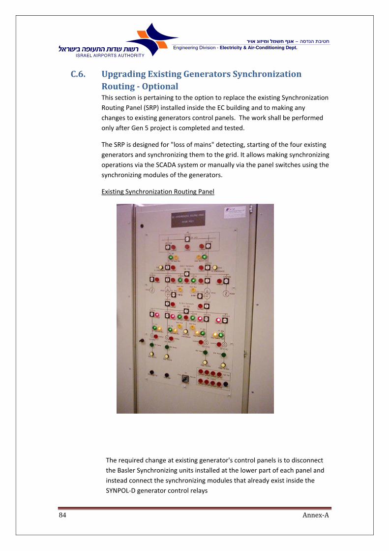
Annex‐A84
C.6. UpgradingExistingGeneratorsSynchronizationRouting‐OptionalThis section is pertaining to the option to replace the existing Synchronization
Routing Panel (SRP) installed inside the EC building and to making any
changes to existing generators control panels. The work shall be performed
only after Gen 5 project is completed and tested.
The SRP is designed for "loss of mains" detecting, starting of the four existing
generators and synchronizing them to the grid. It allows making synchronizing
operations via the SCADA system or manually via the panel switches using the
synchronizing modules of the generators.
Existing Synchronization Routing Panel
The required change at existing generator's control panels is to disconnect
the Basler Synchronizing units installed at the lower part of each panel and
instead connect the synchronizing modules that already exist inside the
SYNPOL‐D generator control relays
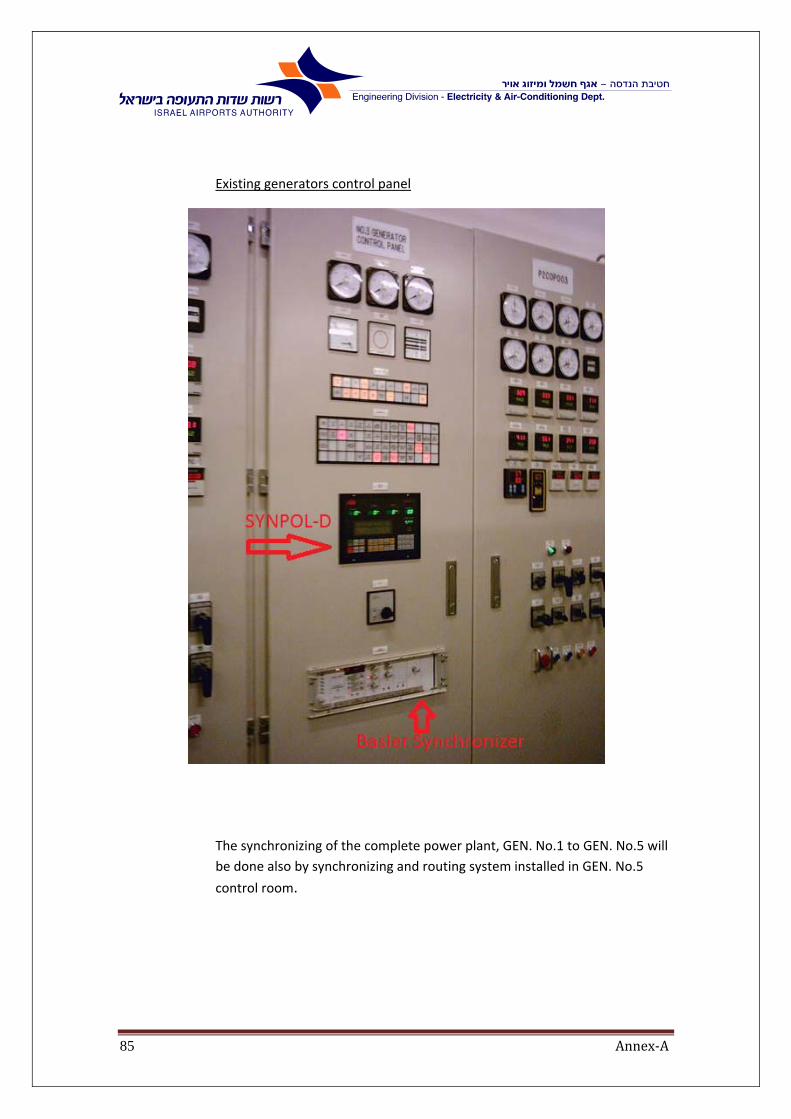
Annex‐A85
Existing generators control panel
The synchronizing of the complete power plant, GEN. No.1 to GEN. No.5 will
be done also by synchronizing and routing system installed in GEN. No.5
control room.

Annex‐A86
C.6.1. DescriptionoftheCurrentOperationIn general, each generator has to be synchronized with the existing electrical
power supply system before connection can be done.
There are a few common cases of existing generator synchronization
procedures, as follows:
C.6.1.1. Case1:NoPowerSupplyfromIEC;1. first generator has to start (Dead Bus)
2. No synchronization is needed in this case
3. Main 22kV entrance breakers should be disconnected
4. The generator might be connected to the bus when voltage
and frequency generated by it are within normal limits
5. The first portion of essential loads (first priority) should be
reconnected consecutively while the generated power
increases
C.6.1.2. Case2:NopowersupplyfromIEC22kV;
1. Main entrance breakers should be disconnected
2. Tie breakers 102 and 320 are opened. No generators are
working connected to the same busbar in the 6.3kV switch‐
board as the target generator.
3. This case is similar to the case described in the previous sub‐
paragraph
C.6.1.3. Case3:NopowersupplyfromIEC;1. one generator is working
connected to the same field in 6.3kV switchboard as the target
generator
2. 22kV Main entrance breakers should be disconnected. Tie
breakers 102 and 320 are opened.
3. The target generator should be synchronized with
corresponding field in 6.3kV switch‐board.

Annex‐A87
C.6.1.4. Case4:NopowersupplyfromIEC;1. one generator is working
connected to the other field in 6.3kV switchboard as the
target
generator
2. 22kV Main entrance breakers should be disconnected. Tie
breakers 102 and 320 are closed.
3. This case is similar to the case described in the previous sub‐
paragraph
C.6.1.5. Case5:NopowersupplyfromIEC1. 22kV Main entrance breakers should be disconnected. Tie
breakers 102 and 320 are opened.
2. There are working generators connected to both fields in 6kV
switchboard
3. Generator G300 should be synchronized with non‐
corresponding field in 6.3kV switch‐board in case tie breaker
320 is closed.
C.6.1.6. Case6:Electricaldistributionsystemisfedfromemergencygenerators
1. 22kV Main entrance breakers are opened. Tie breakers 102
and 320 are closed. IEC power supply is restored.
2. All working generators should be synchronized simultaneously
with 22kV Main entrance to enable 22kV Main entrance
breaker closing.

Annex‐A88
C.6.1.7. Case7:Electricaldistributionsystemisfedfromemergency generators
1. 22kV Main entrance breakers are opened. Tie breakers 102
and 320 are opened. IEC power supply is restored.
2. All working generators connected to each field in 6.3kV
switchboard should be synchronized simultaneously with
corresponding 22kV Main entrance, to enable corresponding
22kV Main entrance breaker to close.
C.6.1.8. Case8:Peakshavingmodeisconsideredtobeasfollows:
1. Case 8.1: Both 22kV Main entrance breakers (101, 201) are
closed.
The tie breakers 102, 320 are opened, i.e., the system is
divided to two independent parts.
In each part of the system the generators should be started
one‐by‐one, independently, and synchronized with
corresponding 6.3kV bus.
2. Case 8.2: One 22kV Main entrance breaker (either 101 or 201)
is closed, while the other is opened.
The tie breaker 102 is closed, while the tie breaker 320 is
opened.
The generators should be started and synchronized
consecutively with corresponding 6.3kV bus.
There is no need to connect the grounding transformers and
disconnect transformers' neutral grounding, in peak shaving mode,
when the local generators are working in parallel with normal IEC
power supply.

Annex‐A89
Synchronizing routing panel is supervised by the SCADA system providing
updated parameters (GV ‐ generator voltage, BV ‐ bus voltage) to each
generator accordingly to desired connection point. The parameters for
synchronization (voltage, frequency) are measured by means of potential
transformers from both sides of the breaker (CB) that makes the connection.
The table below lists the potential transformers supplying the
measurements for each mentioned case.
GEN100 GEN200 GEN300
GV BV CB GV BV CB GV BV CB
Case 1 PT304 PT301 304 PT303 PT301 303 PT313 PT312 313
Case 2 PT304 PT301 304 PT303 PT301 303 PT313 PT312 313
Case 3 PT304 PT301 304 PT303 PT301 303 PT313 PT312 313
Case 4 PT304 PT301 304 PT303 PT301 303 PT313 PT312 313
Case 5 PT312 PT301 320 PT312 PT301 320 PT312 PT301 320
Case 6 PT102 PT101 101 PT102 PT101 101 PT102 PT101 101
PT202 PT201 201 PT202 PT201 201 PT202 PT201 201
Case 7 PT102 PT101 101 PT102 PT101 101 PT202 PT201 201
Case 8.1 PT304 PT301 304 PT303 PT301 303 PT313 PT312 313
Case 8.2 PT304 PT301 304 PT303 PT301 303 PT313 PT312 313
The synchronization routing panel is a stand‐alone system, driven by its own
PLC, but it has data handshake with the EC Electrical Distribution Main PLC.
Each breaker, mentioned in the table above should be checked for automatic
operation mode, truck in operating position and protection relays non‐lockout
status, while each relevant potential transformer should be checked for phase
balance and under‐voltage conditions before the requested routing may be
performed.
In the case of IEC power supply total failure, all available generators should be
started, synchronized and connected to electrical system as soon as possible.

Annex‐A90
When the main IEC power supply is restored, the previous connected
emergency generators should remain working for a certain period of time, thus
creating a situation similar to peak shaving mode as described further. After this
time delay, and verifying that the normal supply is steady, the generated power
should be decreased close to zero and the generators should be disconnected
and stopped one by one.

Annex‐A91
D. ChapterD‐MediumVoltage
D.1. POWERTRANSFORMER
D.1.1. GeneralThis specification covers the requirements for the supply and installation of indoor, oil filled, three phase, and two copper windings, Generator step up power transformer.
The contractor shall furnish and install complete, new power transformers, auxiliary systems and works as specified herein and required for a complete installation, start‐up, operating and commissioning.
Transformers shall be operated in electrical polluted environment that includes large motors and large frequency converters. The manufacturer shall include in his proposal, a description of his design considerations for transformers operation under these conditions.
The transformer intended to be connected directly to a generator; therefore it should meet load rejection conditions as described in IEC 60076‐1.
D.1.2. GeneralData:1. 10 MVA ONAN/ONAF (Sizing can be changed according to Generator
MVA rating + 10%)
2. 11/22 KV
3. 50Hz
4. Connection group: Ynd11
5. Uk%= 8%
6. Maximum winding temperature rise of 55ºC at full ONAN/ONAF capacity
7. Maximum oil temperature rise of 50ºC at full ONAN/ONAF capacity
8. Oil preservation system.
9. 22kV neutral side may be floated or connected to the ground via grounding resistor.
10. NLTC of 0, ±2.5, ±5,±7.5% .
D.1.3. SupplyandInstallationThe present specifications shall mean supply and installation, which will include the following for every part of the work and for the whole work:
1. Factory witness tests
2. Storage and delivery to site
3. Coordination with other contractors.
4. Installation on site
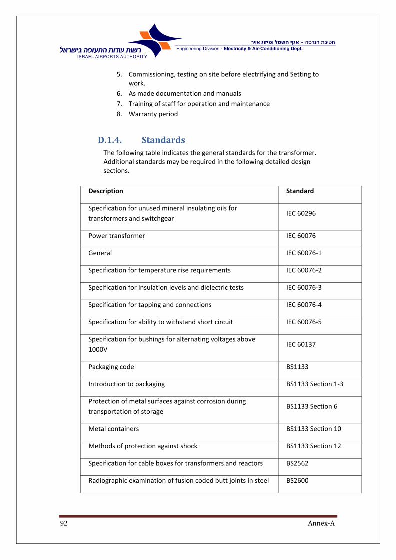
Annex‐A92
5. Commissioning, testing on site before electrifying and Setting to work.
6. As made documentation and manuals
7. Training of staff for operation and maintenance
8. Warranty period
D.1.4. StandardsThe following table indicates the general standards for the transformer. Additional standards may be required in the following detailed design sections.
Description Standard
Specification for unused mineral insulating oils for
transformers and switchgear IEC 60296
Power transformer IEC 60076
General IEC 60076‐1
Specification for temperature rise requirements IEC 60076‐2
Specification for insulation levels and dielectric tests IEC 60076‐3
Specification for tapping and connections IEC 60076‐4
Specification for ability to withstand short circuit IEC 60076‐5
Specification for bushings for alternating voltages above
1000V IEC 60137
Packaging code BS1133
Introduction to packaging BS1133 Section 1‐3
Protection of metal surfaces against corrosion during
transportation of storage BS1133 Section 6
Metal containers BS1133 Section 10
Methods of protection against shock BS1133 Section 12
Specification for cable boxes for transformers and reactors BS2562
Radiographic examination of fusion coded butt joints in steel BS2600

Annex‐A93
Description Standard
Method of radiographic examination of fusion welded
circumferential butt joints in steel pipes BS2910
Specification for granular desiccant silica gel impregnated with
cobalt chloride BS3523
ISO metric screw threads BS3643
Principle and basic data BS3643 Part 1
Specification for selected limits of size BS3643 Part 2
Specification for ISO metric black hexagon bolts, screws and
nuts. Metric units. BS3692
Specification for approval testing of welders when welding
procedure approval is not required BS4872
Specification for tests on hollow insulators for use in high
voltage electrical equipment
IEC 233
Code of practice for protective coding of iron and steel
structures against corrosion BS5493
Specification for sound level meters IEC 60651
Determination of transformer and reactor sound levels IEC 60551
Specification for unfilled enclosures for the dry termination of
HV cables for transformers and reactors BS6435
Guide to loading of oil‐immersed power transformers IEC 60354
Power transformers – oil draining devices DIN42551
Deaerator and filling nozzle for transformer DIN42553
Thermometer case for oil immersed transformers DIN42554
Transformers – magnetic oil indicator DIN42569
Screwed glands for cables DIN46320

Annex‐A94
D.1.5. TransformerRatingsandOtherDataRatings of the transformer shall be based on the following temperature conditions:
1. Winding temperature rise as measured by resistance at 55C. 2. Top oil temperature rise as measured by thermometer at 50C. 3. Maximum temperature of the cooling air as measured by thermometer
at 40C.
D.1.6. LossesThe maximum permitted losses, with no tolerance allowed, on nominal tap is:
Power No load (excitation) Load (copper)
At 10MVA 9KW 40KW
D.1.7. CoolingSystemThe Transformer shall be air cooled, ONAN /ONAF. The cooling system shall be divided into sections (or coolers), one of them being considered a reserve section. The reserve cooling section shall normally be in operation to maintain free oil circulation. In a forced outage of any cooling sections, cooling shall continue without exceeding temperature rise limits.
Pipe connections to the cooling sections shall be removable, and the cooling sections shall be replaceable without lowering the oil level in the tank. Vent holes with plugs shall be provided at the top and drain holes with plugs at the bottom of each radiator.
The operation alternatives of the cooling system (ONAN/ONAF) shall allow operating the transformer at the power indicated in Paragraph “C” and in the temperature conditions indicated in “Site Conditions”.
Provision shall be made for using power supply sources 3x400 volts, 50 Hz, provided by the purchaser.
A complete control system for automatic operation of the cooling system shall be provided, including automatic transfer from one operation alternative ONAN/ONAF to another. An alarm shall be included for exceeding the limit temperature conditions. The control system shall be operated from the winding temperature and shall comprise the following:
Winding temperature simulator device with thermal element mounted in a well and responsive to the hottest simulated winding temperature of the transformer or manufacturer’s standard.
Switching for automatic and manual control.
Wiring for cooling equipment.
Remote control circuits of the cooling system shall include:
Position signal of the selector switch for automatic or manual control.
Alarm signal for power source failure.
Annex‐A95
Alarm signal for circuit‐breaker or contactor trip by protection or manual operation.
Winding and oil temperature remote LCD unit, to be installed on the front door of the 12kV or 22kV panel.
The contractor shall supply two N.O/N.C sets of dry contacts for all alarms and indicators.
Contractor shall include the “Power and Control Voltage Supply Diagram” and the “automatic Control Design” in the proposal.
D.1.8. TestsThe transformer shall be subjected to the following production routine, mechanical, dielectric, etc., type tests at the manufacturer’s plant to check the quality and uniformity of the workmanship and materials used in manufacture of the transformer. The tests shall be performed according to applicable IEC Publications, unless otherwise specified.
Production tests, routine tests, mechanical tests, dielectric tests, etc., shall be performed as specified, and copies of the relevant test reports shall be submitted to the CPM for his review and approval.
Contractor shall also submit test data to prove that the design has the capability to meet all the ratings and performance specified.
Contractor shall submit copies of test procedures to be performed at the factory, and on‐site, after installing the transformers and during operation.
Each transformer shall be subjected to all routine tests according to latest IEC Publication 60076‐1, unless otherwise specified.
Measurement of impedance voltage, short circuit impedance and load loss shall be performed at principal tap, and on the highest and lowest tap.
The tank and oil filled compartments shall be tested for oil tightness. The test shall be performed according to manufacturer’s standards. The contractor shall supply with his required submittals, manufacturer’s data which indicates how the oil leak test will be performed.
Mechanical test shall be made on tanks, oil level gauge, etc., for proper functioning.
Type tests shall include the following tests:
Measurement of acoustic sound level (guaranteed). The measurement of sound level shall be performed according to NEMA standard TR‐1. The test shall be made on the energized transformer at no‐load.
Temperature tests.
Oil temperature rise at top of tank 50ºC.
Expected temperature rise of windings under rated conditions 55ºC.
Insulation level and dielectric tests.

Annex‐A96
After assembly, the transformer shall be subjected to high voltage dielectric tests, according to IEC Publication 60076‐3, and amendment, unless otherwise specified. During these tests, the transformer shall be equipped with the bushings that will be used in permanent operation.
Power frequency separate source tests.
Lightning impulse on line terminals.
Lightning impulse on neutral terminal.
Induced over‐voltage test.
Measurement of the polarization index.
The rated withstand voltage of the windings and the application of the above tests shall be as follows:
1. Rated lightning impulse withstand voltage 1.2/50 sec: 22KV line terminal‐ 125kv peak
22kV neutral terminal‐ 125 kV peak
11kV line terminal‐ 75 kV peak
2. Rated short duration power frequency withstand voltage:
22kV line terminal‐ 50kV rms
11kV line terminal‐ 28kV rms
22kV neutral terminal‐ 50kV rms
The lightning impulse test shall be made on each unit, for both line terminals, in the following order:
1st‐Reduced voltage full wave ‐ one application
2nd‐Chopped wave ‐ two application
3rd ‐ Full wave ‐ one application
The peak value of the chopped impulse and the time to chopping shall be as follows:
22KV ‐ 125kV peak
11kV ‐ 75 kV peak
Time to chopping 2 sec Impulse tests on transformer neutral shall consist of one (1) reduced voltage full wave and two (2) full wave tests. These tests shall be performed on each transformer.
Neutral current measurement shall follow each reduced and full voltage wave if current records are not obtained simultaneously with voltage records.
Measurement of polarization index:
Measurement of the polarization index (the ratio of apparent insulation resistance after 10 min. to that after 1 min. after the application of testing voltage), shall be made with 5kV DC voltages.
The measurement shall be done:
Between HV winding and LV winding, (tank connected to guard)

Annex‐A97
Between HV winding and tank (LV connected to guard) Between HV winding and tank (LV connected to guard) Between LV winding and tank (HV connected to guard) The tank shall be grounded during all measurements
Test report for the polarization index measurement as well as variation of apparent winding insulation resistance with time shall be provided.
Each transformer shall be designed and constructed to withstand thermal and dynamic effects of external short circuits, according to IEC Publication 60076‐5, without damage.
Contractor shall comply with measurements indicated in the following table.
Subject 22kV –side 11kV‐ side
Number Q. Bushing 4 3
Rated withstand voltage (kV Bil) 125 75
Impulse withstand voltage positive and negative (kV peak)
125 75
One minute power frequency test ( kV rms)
50 28
Creepage not less than (mm) 800 450
No of HV arcing horn gaps (not less than 120o)
2 2
The client explicitly requires that Contractor submit data from the manufacturer that indicates in summary form the type and the name of the manufacturer of all bushings, on the HV side and LV side.
Bushings shall be designed and tested according to IEC Publication 60037. In lieu of this design and testing, the manufacturer shall design and test bushings in accordance with approved local procedures and standards, suitable for the applicable service conditions, and shall submit a certified statement indicating that the bushings comply with all Contract requirements.
Bushings shall have temperature limits according to IEC Publication 60137, clause 10.
Transformer leads for the high voltage and low voltage windings and LV Neutral shall be brought out through the cover of the transformer tank for connection to conductors/cables.

Annex‐A98
D.1.9. Structure Studs, as well as their threaded holes, used in various sub‐assemblies in contact with the atmosphere shall be silicone greased before fastening.
The bottom of the transformer shall have a steel skid base, suitable for skidding in direction parallel to both center lines of the tank. A plan with all relevant dimensions shall be provided. Contractor shall submit an accurate plan that indicates all relevant dimensions to the CPM for his review and approval.
Thermally upgraded paper or approved equivalent shall be used for winding insulation.
The tank shall be designed to withstand full vacuum. The construction of the tank shall enable easy removal or installation of bushings and current transformer, without disturbing the leads, emptying the oil from the transformer, or removing the cover.
Painting of the transformer tank, lid, conservator and all other parts shall include:
100 micron hot‐spray galvanizing
150 micron hot‐spray galvanizing layer.
Two 40 Micron (min.) Epoxy based primer layer.
Two 80 Micron (min.) outer gray epoxy glossy paint layer (oven baked).
The finish and painting of the tank shall enable it to satisfactorily withstand the most severe service conditions normally expected or encountered at the site.
Transformer oil shall meet the requirements indicated in GE Specifications for mineral insulating oil, No. A13A3A2 and shall be "NYNAS Inhibited" type.
Technical data and oil test report shall be submitted to the PM for his review and approval.
Oil preservation system shall be provided for protecting oil against atmospheric moisture and oxygen.
Silica‐gel air drier for oil preservation shall be mounted and shall be clearly visible through a glass.
Paint, insulation materials, and all other materials in contact with transformer oil shall not contain any substance that may, to any extent, influence its dielectric properties or result in chemical reactions with the oil, or in any way lead to a deterioration of oil quality.
Manufacturer shall provide two (2) 55 gallon drums over and above the quantity required to fill each transformer tank.
The details of the oil preservation system shall be completely described in the proposal.
The oil preservation system shall be provided with all necessary drain corks, plugs for oil filling, connections to tank, etc.
“Bucholz” fault gas pressure device shall be provided to suit manufacturer’s method of oil preservation.
Annex‐A99
Rating plate shall list the rating of the transformer with forced and natural
cooling at 55C and 65C rise in addition to the data specified in Publication 60076‐1 of the IEC Recommendations.
In order to determine the extent of the field installation, Contractor shall supply manufacturer’s list all items which will be shipped separately. It is understood that items not so listed in Summary of Data will be shipped completely factory installed and factory connected.
D.1.10. ControlcabinetandwiringAll necessary automatic control, motor starters, protective devices, switches, etc. of each transformer shall be assembled in a dust proof and weather‐proof, hot dip galvanized, metal cabinet arranged for satisfactorily mounting on each one of the respective transformer units (Space shall be reserved for future additional cooling equipment switch gear).
The control cabinet shall be accessible from ground level. The cabinet shall be provided with a door for front access, handles, locking facilities (key locks) and all equipment required for local operation.
The cabinet shall be provided with type IP54 environmental protection, according to DIN 40050 and shall be fit for plant "Site conditions".
Small wiring for control or accessory equipment shall have 600 volts, 90C, polyvinyl chloride insulation with flameproof braid covering or cross‐linked polyethylene, and shall be installed in standard galvanized rigid steel conduits, or electrical metallic tubing or ducts, with watertight joints.
Small wiring enclosures shall be grounded.
A weather proof box shall be provided for terminating the conduits and wiring for exterior connections.
Drain holes shall be provided at low points of boxes and conduits.
Power and control circuit conductors shall be adequately dimensioned and shall not be smaller than 2.5 sq. mm.
Control and instrument wiring, alarm leads and instrument transformer secondary connection to incoming cables shall be terminated at terminal blocks. Blocks shall be spaced to allow 1 1/2 inch clearance on all sides. Extra space shall be provided for training and crossing incoming leads.
Ten (10) free terminals shall be left for future use in each terminal block.
The control cabinet shall be supported by a suitable vibration damping devices.
Compression type (solder‐less) lugs shall be furnished with each terminal block for incoming control wires. The size of these control wires shall be as indicated on the drawing or approved by the CPM.
Provide a 11W, 230VAC PL lamp in each of the enclosures together with a switch that is mounted inside the box.
The assembled control equipment and wiring connections shall be subjected to a one minute test of 2000 VAC at the factory, after fabrication and assembly is complete.

Annex‐A100
D.1.11. AdditionalaccessoriesTransformer shall be furnished with the following additional accessories:
1. Lifting eyes for transformer cover and lugs for safely lifting the assembled transformer.
2. Four (4) jacking points shall be provided at a height not less than 350mm to transformer foundation. Location and relevant dimensions shall be submitted to the CPM for approval.
3. Pulling eyes shall be provided at the base of each transformer for skidding transformer parallel to either center line of the transformer.
4. Provide a thermal image system for indication of hot‐spot temperature. The thermal image system shall include:
a. Standard resistance temperature element for measuring hot spot temperature.
b. Hot spot temperature indicator shall be furnished for the transformer for use with the above resistance temperature element. In case the indicator shall also be used for an alarm signal, it shall be connected to DC auxiliary supply. Hot spot temperature indicator shall be suitable for flush mounting on the control panel.
c. The heating resistance shall be fed by a bushing current transformer. A bushing current transformer shall be provided for this purpose on the HV winding terminal. The rating and other parameters of bushing current transformers shall be established by the manufacturer, suitable for measuring.
5. Four (4) grounding pads with tapped holes, one on each side of the transformer. Locations shall be as indicated on the relevant drawings.
6. Pressure Relief Devices
7. Oil level gauge, magnetic type, with low level alarm contacts for 220 VDC ungrounded service.
8. Oil drain and filter valve, (2 inch minimum).
9. Oil sampling connection (3/8 inch minimum) placed on the drain side of the drain valve.
10. Top connection with 1 inch, or larger, valve for oil purifier.
11. Dial type hot oil thermometer with manually reset maximum indicating hand and 250 VDC ungrounded alarm contacts to close on high temperature.
Sudden pressures relay (Bucholz)
A Bucholz or sudden pressure relay shall be supplied, to protect the transformer against damage due to internal faults.
The relay shall operate on the base of pressure change. The relay shall have at least two sets of N.O/N.C contacts, one to activate the alarm and the other for trip. The relay shall be installed at the connection pipe between the highest point of the tank and the oil conservator.
Annex‐A101
The contractor shall install valves, with SCADA indication contacts, to bypassing the relay and for taking gas samples (while the transformer is loaded).
D.2. AUXILIARYTRANSFORMERS
D.2.1. GeneralThis paragraph covers the specifications and requirements for a low losses, oil immersed, sealed tank, three phase, two copper windings and 22/0.4kV power transformer. The transformer shall be used for energizing VFD motors and standard domestic loads.
Two transformers shall be supplied:
1. Rated power for type 1 1600kVA
2. Rated power for type 2 630kVA
D.2.2. SystemdataThe system has the following characteristics:
Rated system voltage (line to line) 22kV ± 10%
Nominal Highest system voltage (line to line) 24kV
Frequency 50Hz ± 4%
Utility side grounding Grounding
transformer
For calculation of the short circuit current at transformer terminals, the
short circuit power of the 22kV system shall assume to be 750MVA.
The power transformer will be installed indoor.
The transformer shall be connected to 22kV utility network.

Annex‐A102
D.2.3. StandardsDescription Standard
Specification for unused mineral insulating oils for
transformers and switchgear IEC 60296
Power Transformer IEC 60076
General IEC 60076‐1
Specification for temperature rise requirements IEC 60076‐2
Specification for insulation levels and dielectric tests IEC 60076‐3
Specification for tappings and connections IEC 60076‐4
Specification for ability to withstand short circuit IEC 60076‐5
Specification for converter transformers for industrial
applications IEC 61378‐1
Three‐phase oil‐immersed distribution transformers 50 Hz,
from 50 kVA to 2500 kVA with highest voltage for equipment
not exceeding 36 kV
DIN EN 50464‐1/40/
Specification for bushings for alternating voltages above
1000V IEC 60137
Packaging code BS 1133
Introduction to packaging BS 1133 Section 1‐3
Protection of metal surfaces against corrosion during
transportation of storage BS 1133 Section 6
Metal containers BS 1133 Section 10
Methods of protection against shock BS 1133 Section 12
Specification for cable boxes for transformers and reactors BS 2562
Radiographic examination of fusion coded butt joints in steel BS 2600
Method of radiographic examination of fusion welded
circumferential butt joints in steel pipes BS 2910
Specification for granular desiccant silica gel impregnated
with cobalt chloride BS 3523
ISO metric screw threads BS 3643
Principle and basic data BS 3643 Part 1
Specification for selected limits of size BS 3643 Part 2
Specification for ISO metric black hexagon bolts, screws and
nuts. Metric units. BS 3692

Annex‐A103
Description Standard
Specification for approval testing of welders when welding
procedure approval is not required BS 4872
Specification for tests on hollow insulators for use in high
voltage electrical equipment
IEC 60233
Code of practice for protective coding of iron and steel
structures against corrosion BS 5493
Specification for sound level meters IEC 60651
Determination of transformer and reactor sound levels IEC 60551
Specification for unfilled enclosures for the dry termination of
H.V. cables for transformers and reactors BS 6435
Guide to loading of oil‐immersed power transformers IEC 60354
Power Transformers – Oil draining devices DIN 42551
De‐aerator and filling nozzle for transformer DIN 42553
Thermometer case for oil immersed transformers DIN 42554
Transformers – Magnetic oil indicator DIN 42569
Screwed glands for cables DIN 46320
D.2.4. ElectricaldataTransformer rated power at 55C rise (KVA)
Type 1 1600kVA
Type 2 630kVA
Highest primary system voltage (kV) 24
System primary neutral IECo substation
System secondary neutral Solid Ground
Transformer connection group Dyn11
Rated voltage of primary winding (kV) 22kV
Rated voltage of secondary winding (kV) 0.4kV
Duty Continuous

Annex‐A104
Rated lightning impulse withstands voltage. 125 kV peak
Noise levels at 1m 50 db (max.)
Temperature rise limit 55/60ºK
K factor
Type 1 6
Type 2 1
Short circuit impedance voltage: Uk%
Type 1 6%
Type 2 4.5%
Short circuit duration 2s
OFF load tap‐changer:
Full capacity is required for the entire range of
voltage regulation
Number of taps 5
Voltage range (%) +5, +2.5, 0, ‐2.5, ‐5
Rated step voltage (kV) 0.55
At principal tap (‘O’ position), transformer
ratio shall be:
22/0.4kV
Bushings and terminals:
Nominal voltage for MV plug‐in bushing 24kV rms
Rated withstand voltage for MV plug‐in
bushing kV (BIL)
125kV
Rated lighting impulse withstand peak voltage 125kV
Creepage distance LV side: (mm) 90mm as Minimum
Air clearance to earth LV side: (mm 58mm as Minimum

Annex‐A105
D.2.5. Losses:Maximum allowed losses according to Israeli
standard IS 50464 ‐1 for distribution
transformers
Ao Ak
D.2.6. ConstructionTransformer shall be three phase, oil immersed, self‐cooled, designed for indoor installation.
Oil shall be free from PCB (Polychlorinated Biphenyls) and a certificate for "PCB free" shall be submitted.
The core shall be manufactured of grain oriented transformer sheet steel to ensure low core losses, accurate dimensions and flatness. The core shall be glued. Yokes shall be pressed together with steel sections. Steel sheet cutting
angle shall be 45 to reduce losses and noise. The MV and LV windings shall consist of copper wires or copper foils with press board insulation between them.
Transformers shall be equipped with a manual type, off load tap changer. The contacts shall be designed in such a way that an increase in load shall increase the contact pressure. The operating handle shall have a position maker with a latch for each position thus preventing the tap charger from being set between the two positions. The operating handle shall have provisions for a padlock.
Transformer shall have corrugated sheet steel tank cover for increased cooling.
MV bushings shall be according to DIN 42532‐30 and IEC Publication No. 60076.
LV bushings shall be according to DIN 42539. Marking of phase and neutral shall be clear.
Transformer shall have the following paint layers:
1. 100 micron hot‐spray galvanizing layer
2. Two 40 Micron (min.) Epoxy based primer layer.
3. Two 80 Micron (min.) outer grey epoxy glossy paint layer (oven baked).
Transformers shall be vacuum dried while coils are heated. Oil filling shall be
made under vacuum with degassed oil

Annex‐A106
Transformer Tank Hermetic Sealed
Transformer skid type On wheels
D.2.7. TestesEach transformer shall be supplied with its own test report. Testing shall be carried out according to I.E.C 60076 latest edition, and as follows:
D.2.8. TypeTestsType test certificates for the following tests of identical design of transformer shall be submitted with the bid. The certificates shall be issued by a reputable and internationally recognized testing body or the testing laboratory of the manufacturer. The same tests shall be carried out during the acceptance testing of the first consignment of transformers for each transformer rating. Cost of tests shall be included in the price of the transformers.
1. Temperature rise test.
2. Noise level tests.
3. Impulse test.
4. Withstand short circuit test.
D.2.9. RoutineTests1. Transformer ratio.
2. Winding resistance.
3. Vector group test.
4. Short circuit tests to determine load losses and short circuit impedance.
5. No load test to determine no load losses and no load current.
6. Dielectric Tests.
7. Insulation resistance.
8. Induced over voltage withstand test (100 Hz and twice the nominal voltage)
9. Short duration AC test .(power frequency)
10. Oil pressure test on transformer to check against leakages past joints and gaskets.
Contractor shall perform production tests to check the quality and uniformity of the workmanship and materials used in the manufacture of the power transformers.
Contractor shall also submit test data to prove that the design has the capability to meet the ratings and performances specified.
Contractor shall submit a list of all production tests to be performed at the factory and a list of tests to be performed on site, after installing power transformers and during operation.

Annex‐A107
D.2.10. AccessoriesTransformers shall be supplied with the following accessories:
1. MV plug‐in bushings.
2. LV bushing with flat terminal Acc. To DIN 42539.
3. Earth connection. Acc. To DIN 48088.
4. Rating plate.
5. Terminal marking plate.
6. Bi‐directional rollers Acc. To DIN 42561.
7. Lifting lugs.
8. Bi‐directional hauling lugs.
9. Oil drain device Acc. To DIN 42551.
10. DGPT2 protection unit with Dial thermometer.
11. Wheels
12. Safety valve.
Annex‐A108
D.3. NEUTRALGROUNDINGRESISTOR
D.3.1. GeneralNeutral grounding resistor (NGR) shall be connected to the star point of the
generator step‐up transformer at the 22kV side. The NGR shall be energized
via motorized MV disconnect or creating a ground reference point when the
power source is the local generator in island mode.
The rated earth fault current or specified thermal current shall be 500A at 15
seconds. The Bidder shall quote for neutral grounding resistor with final
temperature as per allowable limit due to the specified current for specified
time.
The resistor unit shall be air‐cooled type suitable for installation also at
outdoor locations.
Rated system voltage (line to line): 22kV.
Highest system voltage (line to line): 25.8kV.
System neutral effectively earthed.
Frequency: 50Hz.
For calculation of the short circuit current at transformer terminals, the
short circuit power of the 22kV system shall be assumed to be 750MVA.
D.3.2. Technicaldata
The resistor element shall be made of non‐aging stainless steel or equivalent
corrosion resistant material having high electrical resistivity and low
temperature co‐efficient of resistant. The NGR shall have temperature
limited to the maximum allowable temperature for the material offered
considering the air ambient temperature at site as mentioned earlier.
The resistor unit shall consist of a no. of elements. All the elements shall be
mounted inside the cubicle so as to ensure ease of inspection and
replacement of individual element. The resistors shall be edge‐wound type.
Resistor element shall possess a balanced combination of both mechanical
and electrical properties over the entire intended operating temperature
range without any harmful effect on the elements and their accessories.
All resistor elements constituting the NGR shall be assembled and supported
inside the cubicle in such a way that no distortion or breakage shall occur
during the passage of through fault current to earth.
All element connections shall be bolted type to ensure stable resistance
value throughout the working life of the unit.
Wet process type brown glaze porcelain insulators shall be used for
supporting resistor elements. Porcelain insulators shall have high creepage
value suitable for heavily polluted atmosphere charged with dust particles.

Annex‐A109
D.3.3. EnclosureThe neutral grounding resistor shall have structural steel work enclosed on
all sides and on top by sheet steel having a minimum thickness of 3 mm.
Suitable ventilating louvers shall be provided on sides to ensure proper
ventilation. The louvers shall be provided with fine wire mesh to make it
vermin proof.
Enclosure shall be self‐supporting, weather proof type suitable also for
outdoor mounting having a protection class as indicated in "ratings and
requirements table".
Cubicle shall be complete with a front access door with handles, lock and
also a removable bolted cover. All doors and removable covers shall be
properly gasketed with neoprene rubber gaskets. All cubicle door hinges
shall be concealed type.
Cubicle shall be complete with a suitably mounted cable end box fitted with
removable double compression brass type cable gland for fixing cable gland.
The cable size shall be as indicated in the annexure. Double compression
cable gland and tinned copper lugs shall be provided.
Cubicle shall be provided with suitable base channels for direct bolting to
the foundation at site. All necessary galvanized bolts, nuts, washers etc. shall
be supplied by the Bidder for installation of Cubicle at site.
Cable entry in NGR enclosure shall be from the upper part.
Fine mesh screen of corrosion resistant material shall be furnished on all
ventilating opening to prevent entry of insects.
D.3.4. CurrentTransformerThe toroidal (window type) current Transformer shall be cast resin type,
insulation class ‘B’, suitably mounted inside the NGR cubicle in such a way as
to ensure easy removal and/or maintenance works.
The secondary leads of CT shall have polarity markings as per IS. The
secondary leads shall be brought out to the terminals at terminal box
provided at suitable location completely isolated from high voltage
equipment.
D.3.5. WiringAll internal wiring between control or measuring equipment and terminal
block shall be carried out by PVC insulated grade 2.5 Sq.mm stranded
copper conductor wires.
All wiring shall be suitably ferruled with corresponding wiring identification
marks used in the schematic / wiring diagrams.
All devices and terminal blocks within the terminal box shall be clearly
identified by symbol corresponding to those used on applicable

Annex‐A110
schematic/wiring diagram. 20% spare terminals shall be provided in terminal
block.
D.3.6. GroundingAll parts of enclosure, supporting structures, equipment frames etc. shall be
properly grounded at two points separately.
Cubicle shall be completed with two (2) nos. ground pads, tapped holes and
bolts suitable for connection of 2x150mm2 copper wires.
D.3.7. Tests
D.3.7.1. RoutineTestsThe NGR shall be completely assembled, wired, adjusted and
routine tested as per relevant standards at manufacturer's
works. The tests shall include:
1. Resistance measurement
2. Voltage measurement
3. Insulation resistance measurement
4. Dielectric test
5. Type Tests
Type test reports shall be subject to the approval of Owner. In
case the bidder has to carry out these type tests, all such tests
shall be done at bidders risk and cost within the schedule
specified herein. No deviation in this regard is acceptable.

Annex‐A111
D.3.7.2. DRAWINGS,DATA&MANUALS1. Proposal sheets duly filled in.
2. Scheme showing series/parallel combination of resistor
elements.
3. Dimensional general arrangement drawings showing
constructional features etc. along with necessary
foundation plan.
4. Cable termination details.
5. Technical leaflets on each piece of electrical equipment
along with write up on salient features.
6. Type test certificate of similar type and rating of offered
equipment.
7. Instruction manuals for the complete system. The manual
shall clearly indicate method of installation, checkups and
tests to be carried out before commissioning of the
equipment.
8. Any other relevant drawing or data necessary for
satisfactory installation, operation and maintenance.
Annex‐A112
D.4. MVSwitch‐Gear
D.4.1. General This section includes 22kV and 12kV switchgear.
D.4.2. SubmittalsThe bidder shall submit with the bid the following documents and
information:
1. General structural drawings.
2. Typical cubicle drawings (internal and external) with equipment specified.
3. One line diagram of the switchgear.
4. Technical information and catalogue/data sheet of main equipment,
including breakers, earthling switches, contactors, potential and current
transformers, bus‐bars, protection relays, H.V. fuses, surge arrestors,
control relays, selector switches, etc
D.4.3. DocumentsThe Contractor shall submit within 30 days after notification of award, for
Purchaser’s approval at least the following:
Detailed complete set of diagrams and schemes of the switchgear, such as:
1. General view from all sides.
2. One line diagrams.
3. Internal wiring diagrams and connection of each equipment type.
4. Schematic and wiring diagram for control and measuring circuits of each
field (cubicle).
5. Terminal block and plug ‐ socket unit with internal and external
connection.
6. Detailed drawing for earthing connection of the switchgear.
7. Detailed drawing of all compartments and especially for H.V cable
connection parts.
8. Part list and all technical information of each equipment piece.

Annex‐A113
9. Instruction manuals for all equipment supplied including: maintenance,
testing, diagrams, spare parts.
10. Full computerized protection calculations and settings.
After installation complete the Contractor shall supply final “AS‐MADE”
drawings and acceptance tests documents
D.4.4. QualityAssuranceManufacturer shall maintain a service center capable of providing training,
parts, and emergency maintenance and repairs. Manufacturer shall use an
independent testing agency with experience and capability to satisfactorily
conduct testing indicated in codes. Manufacturer shall supply drawings to
indicate maximum dimensions for switchgear, including clearances between
cubicles and adjacent surfaces and items, based on types and models
indicated.
D.4.5. Delivery&StorageStorage shall prevent condensation or in the equipment. If required, heaters
shall be used.
The equipment shall be shop assembled to ensure proper fit of all
components and shall be disassembled to whatever extent is necessary for
shipping, transporting and handling up to the final location.
All equipment and other items shall be packed suitable for shipping,
transportation and storage until installed.
The Contractor shall furnish and install necessary covers to protect the
equipment from sun, rain, hail, wind, dust and salt spray. Equipment shall be
adequate sealed and protected during shipment to prevent corrosion and
penetration of foreign matter. All exposed surfaces shall be protected, if
required, with a suitable antirust compound or cover until completion of
erection.
All components or accessories shall be suitably tagged to show identification
and service.
Contractor shall submit, prior to installation, a detailed tabulation of all field
mounted items with at least the following information:
1. Item number, consistent with Contractor’s Bill of materials.
2. Contractor’s shop order number (if any).

Annex‐A114
3. Number of items.
4. Manufacturer and/or Supplier, if other than Contractor.
5. Type and catalogue number if listed.
6. Short description including to what bus‐bar system the item belongs.
Contractor shall submit detailed storage instructions for the specially
designed equipment.
D.4.6. CoordinationCoordination features of controllers and accessory devices with pilot devices
and control circuit to which they connect. Coordinate features, accessories,
and functions of each cubicle with the ratings and characteristics of the
supply circuit, the required control sequence, and the duty cycle of the load.
D.4.7. InstallationandConnectionInstall cubicle according to manufacturer’s written instructions.
Anchor each cubicle to steel channel sills arranged and sized according to
manufacturer’s written instructions. Attach by tack welding or bolting. Level
and grout sills flush with mounting surface. Tighten bus joints, electrical
connectors, and terminal bolts according to manufacturer’s published
torque tightening values. Where manufacturer’s torque values are not
indicated, use those specified in UL 486A and UL86B.
D.4.8. CommissioningFor testing provide services of a qualified independent testing agency to
perform specified testing procedures: Perform on each cubicle visual and
mechanical inspection and electrical test. Certify compliance with test
parameters. Remove and replace malfunctioning units with new units, and
retest. Simulate normal and fault operation conditions and verify operation
of all protection, measuring metering and control functions. Inspect interior
and exterior of each cubicle. Remove paint splatters and other spots, dirt,
and debris. Touch up scratches and mars of finish to match original finish.
Clean devices internally, using methods and materials recommended by
manufacturer. Participate in commissioning of the entire system with all
other concerned contractor/suppliers.

Annex‐A115
D.5. MVswitchboardenclosures
D.5.1. StandardsEnclosures shall be designed, constructed and tested in accordance with the
requirements of the latest relevant published recommendations of the
International Electromechanical Commission (IEC) and their amendments for
metal clad switchgear Internal ARC Proof. All aspects, tests, etc. not covered
by IEC Recommendations shall be made according to the latest published
issue of official or otherwise approved standards of manufacturer's country.
In such cases, the standards themselves shall be supplied.
The relevant standards are:
IEC 60038 IEC standard voltages
IEC 60044‐1 Instrument transformers ‐ Part 1: Current
transformers
IEC 60044‐2 Instrument transformers ‐ Part 2 : Inductive
voltage transformers
IEC 60044‐3 Instrument transformers ‐ Part 3: Combined
transformers
IEC 60044‐5 Instrument transformers ‐ Part 5: Capacitor
voltage transformers
IEC 60056 High‐voltage alternating‐current circuit‐breakers
IEC 60068‐1 Environmental testing ‐ Part 1: General and
guidance
IEC 60068‐3‐3 Environmental testing ‐ Part 3: Guidance. Seismic
test methods for equipment
IEC60068‐2‐6 Environmental testing ‐ Part 2‐6: Tests ‐ Test Fc:
Vibration (sinusoidal)
IEC 60068‐2‐27 Environmental testing ‐ Part 2‐27: Tests ‐ Test Ea
and guidance: Shock
IEC 60068‐2‐60 Environmental testing ‐ Part 2: Tests ‐ Test Ke:
Flowing mixed gas corrosion test
IEC 60099‐1 Surge arresters ‐ Part 1: Non‐linear resistor type
gapped surge arresters for a.c. systems
IEC 60099‐4 Surge arresters ‐ Part 4: Metal‐oxide surge
arresters without gaps for a.c. systems
IEC 60099‐5 Surge arresters ‐ Part 5: Selection and application
recommendations
IEC 60099‐6 Surge arresters ‐ Part 6: Surge arresters
containing both series and parallel gapped
Annex‐A116
structures ‐ Rated 52 kV and less
IEC 60137 Insulated bushings for alternating voltages above
1000 V
IEC 60255‐1 Measuring relays and protection equipment ‐ Part
1: Common requirements
IEC 60255‐3 Electrical relays ‐ Part 3: Single input energizing
quantity measuring relays with dependent or
independent time
IEC 60255‐5 Electrical Relays ‐ Part 5: Insulation coordination
for measuring relays and protection equipment ‐
Requirements and tests
IEC 60255‐6 Electrical relays ‐ Part 6: Measuring relays and
protection equipment
IEC 60255‐11 Measuring relays and protection equipment: Part
11: Interruptions to and alternating component
(ripple) in a.c and d.c. auxiliary energizing input of
measuring relays and protection equipment
IEC 60255‐12 Electrical relays ‐ Part 12: Directional relays and
power relays with two input energizing quantities
IEC 60255‐13 Electrical relays ‐ Part 13: Biased (percentage)
differential relays
IEC 60255‐16 Electrical relays ‐ Part 16: Impedance measuring
relays
IEC 60255‐25 Electrical relays ‐ Part 25: Electromagnetic
emission tests for measuring relays and
protection equipment
IEC 60255‐26 Electrical relays ‐ Part 26: Electromagnetic
compatibility requirements for measuring relays
and protection equipment
IEC 60255‐27 Measuring relays and protection equipment ‐ Part
27: Product safety requirements
IEC 60265‐1 High‐voltage switches ‐ Part 1: Switches for rated
voltages above 1 kV and less than 52 kV
IEC 60282‐1 High‐voltage fuses ‐ Part 1: Current‐limiting fuses
IEC 60282‐2 High‐voltage fuses ‐ Part 2: Expulsion fuses
IEC 60282‐3 Specification for high‐voltage fuse‐links for motor
circuit applications
IEC 60470 High‐voltage alternating current contactors and
contactor‐based motor starters
IEC 60529 Classification of Protection Provided by
Enclosures.
IEC 60721‐2‐1 Classification of environmental conditions ‐ Part
Annex‐A117
2‐1: Environmental conditions appearing in
nature ‐ Temperature and humidity
IEC 60947‐1 Low‐voltage switchgear and controlgear ‐ Part 1:
General rules
IEC 60947‐5‐1 Low‐voltage switchgear and controlgear ‐ Part 5‐
1: Control circuit devices and switching elements ‐
Electromechanical control circuit devices
IEC 60694 Common specifications for high‐voltage
switchgear and controlgear standards
IEC 61000‐4‐1 Electromagnetic compatibility (EMC) ‐ Part 4‐1:
Testing and measurement techniques ‐ Overview
of IEC
IEC 61000‐4‐2 Electromagnetic compatibility (EMC) ‐ Part 4‐2:
Testing and measurement techniques ‐
Electrostatic discharge immunity test
IEC 61000‐4‐3 Electromagnetic compatibility (EMC) ‐ Part 4‐3:
Testing and measurement techniques – Radiated;
radio‐frequency; electromagnetic field immunity
test
IEC 61000‐4‐4 Electromagnetic compatibility (EMC) ‐ Part 4‐4:
Testing and measurement techniques ‐ Electrical
fast transient/burst immunity test
IEC 61000‐4‐5 Electromagnetic compatibility (EMC) ‐ Part 4‐5:
Testing and measurement techniques ‐ Surge
immunity test
IEC 61000‐4‐6 Electromagnetic compatibility (EMC) ‐ Part 4‐6:
Testing and measurement techniques ‐ Immunity
to conducted disturbances; induced by radio‐
frequency fields
IEC 61000‐4‐8 Electromagnetic compatibility (EMC) ‐ Part 4‐8:
Testing and measurement techniques ‐ Power
frequency magnetic field immunity test
IEC 61000‐4‐11 Electromagnetic compatibility (EMC) ‐ Part 4‐11:
Testing and measurement techniques ‐ Voltage
dips; short interruptions and voltage variations
immunity tests
IEC 61000‐6‐2 Electromagnetic compatibility (EMC) ‐ Part 6‐2:
Generic standards ‐ Immunity for industrial
environments
IEC 61140 Protection against electric shock ‐ Common
aspects for installation and equipment
IEC 61850 all parts Communication networks and systems in

Annex‐A118
substations
IEC 61936‐1 Power installations exceeding 1 kV a.c. ‐ Part 1:
Common rules
IEC 62271‐1 High‐voltage switchgear and controlgear – Part 1:
Common specifications
IEC 62271‐3 High‐voltage switchgear and controlgear – Part 3:
Digital interfaces based on IEC 61850
IEC 62271‐4 High‐voltage Switchgear and Controlgear ‐ Part 4:
Use And Handling of Sulphur Hexafluoride (sf[6])
IEC/EN 62271‐
100
High‐voltage switchgear and controlgear – Part
100: High‐voltage alternating‐current circuit‐
breakers
IEC 62271‐101 High‐voltage switchgear and controlgear – Part
101: Synthetic testing
IEC/EN 62271‐
102
High‐voltage switchgear and controlgear – Part
102: Alternating current disconnectors and
earthing switches
IEC/EN 62271‐
105
High‐voltage switchgear and controlgear – Part
105: Alternating current switch‐fuse combinations
IEC 62271‐107 High‐voltage switchgear and controlgear – Part
107: Alternating current fused circuit‐switchers
for rated voltages above 1 kV up to and including
52 kV
IEC/EN 62271‐
200
High‐voltage switchgear and controlgear – Part
200: A.C. metal enclosed switchgear and
controlgear for rated voltages above 1 kV and up
to and including 52 kV
IEC 62271‐202 High‐voltage switchgear and controlgear – Part
202: High‐voltage/low voltage prefabricated
substation
IEC/TR 62271‐300 High‐voltage switchgear and controlgear – Part
300: Seismic qualification of alternating current
circuit‐breakers
IEC/TR 62271‐301 High‐voltage switchgear and controlgear – Part
301: Dimensional standardization of terminals

Annex‐A119
D.5.2. TestsAll components and materials forming part of the enclosure and the main
circuit equipment shall comply with this Specification and the IEC
Recommendation as specified. The contractor shall submit with his offer,
certified type test reports of the offered enclosures and circuit breakers.
In case of equipment or cubicle parts assembled or not built by the original
manufacturer but by other contractor, it is required that the contractor shall
have QA and QC approved by original manufacturer and the work shall be
performed according to original manufacturer’s drawings to make sure that
the cubicles are identical to the type tested.
The Contractor shall submit to the owner's representative a check list of all
components integrated into the enclosure and the enclosure itself, for his
approval.
All tests shall be carried out at the Contractor’s facilities.
The Purchaser shall have the right to inspect and witness all tests.
The Contractor shall conduct on site the acceptances test, including:
1. Insulation test.
2. Functional operation tests (including electrical and
electromechanical interlocks).
3. Calibration and protection devices.
4. Calibration and measuring devices.

Annex‐A120
D.5.3. EnclosuremetalworkEach enclosure type shall have test certificates and approvals of a licensed
standard institution.
Locking bar with waterproof double bit cam lock, which is exchangeable for
square or triangle spindle plugs.
Hinges shall be screwed to the cabinet and shall protrude neither into the
door aperture nor into the cabinet interior, allowing doors to open to 120.
The following shall define treatment and painting of exposed ferrous surface
for metal surface for metal construction of electrical switchboards. All such
treatment and painting shall be carried out by automated equipment.
Material used for construction shall be cold rolled steel sheet, spec ‐ SD ‐
oiled.
Pre‐treatment of metal surfaces shall be automated and consist of the
following:
Oil, grease and similar contaminants shall be removed by alkali solvent
spray at temperature up to 60CPhosphatic layer by means of iron
phosphate spray at temperature up to 60C.Clean water wash. Drying in
oven at temperature of 120C.
Painting metal surfaces shall be automated based on electrostatic
application of specially designed epoxy polyester powders.
Application shall be accomplished by means of industrial robots.
Application to areas with low accessibility shall be completed manually
where necessary using suitable epoxy handgun equipment.
Thickness of paint layer shall be 30 microns.
Color shall be RAL 7030 or RAL 1011 or equally approved.
Resistance to peeling shall be DIN 53151 standard.
Elasticity of paint layer shall be to DIN 53156 standard.
The coated surface shall be baked, up to a temperature of 200C. Exact
temperature adjustment shall be made in accordance with thickness of
metal and conveyer belt.
All application equipment shall be adjusted and controlled to produce a
smooth even layer of uniform thickness over all required surfaces
according to IEC 68‐2‐11.Properties of paint finish:
Impact strength > 1Kg/50cm.

Annex‐A121
Heat resistance 24 hours at 140C.
Corrosion resistant for a minimum of 200 hours against 30% citric acid,
petrol or alcohol.
Internal partitions shall be galvanized with chrome passivation.
All components of the same rating and construction shall be interchangeable.
Metal sheets, covers and doors shall be of evenly and smooth rolled steel
sheets of two (2) mm thickness (minimum).
Rigidity of structure, doors and covers shall be achieved by properly welded or
bent ribs.
The metal enclosure shall be of steel sheets and shall assure complete
protection of persons from approach to live parts or to internal moving parts.
Vent openings shall be protected so as to prevent the access of vermin, snakes
or large insects. The floor surface, even if not metallic, shall be considered as
part of enclosure for this purpose. A sheet metal floor shall be provided
wherever trenches exist under switchgear.
The enclosure, covers, partitions and front of circuit breaker, where it serves as
a cover, shall be strong enough to provide adequate protection to persons from
the hot gases and the instantaneous pressure caused by a fault arc, even
though, the purpose of the enclosure and its compartments is to limit the
damage caused by such an arc. Moreover, each compartment shall have a
suitable vent opening or cover to relieve such pressures.
Covers shall conform with all the requirements of the metal enclosure. Use 10
mm diameter, minimum, hexagon bolts to fasten covers.
Partitions shall be of the same steel sheet as the covers, or of other material of
equivalent mechanical strength which complies with all the mechanical
requirements, non‐burning and not containing carbon, and which includes an
electrically incorporated grounded potential that is not temperature or
humidity affected.
Conductors passing through partitions shall be protected by bushings.
Mounting of these bushings shall be secured by proper means and supports.
Removable contact arrangements in circuit breaker case construction shall
provide the completion of the insulation and shall be an integral part of the
circuit breaker and shall be airtight. Bushings will not be required in this case.
The complete withdrawing arrangement shall be tested at all positions with
relevant test of the circuit breaker.
Annex‐A122
The enclosure shall be mounted on a base frame for each row, constructed to
form a self‐supporting rigid construction despite its being placed on the floor
foundations.
Each compartment, except the instrument compartments shall be provided
with heating elements. The heating elements shall be fitted so as to enable
their replacement even while the fixed contacts of the removing arrangement
of the circuit breaker are live.
A grounding conductor shall be provided running the whole length of the metal‐
clad switchgear. The terminal of the conductor shall be brought out of the
enclosure from each side with a 17 mm diameter bore for the connection of the
external grounded conductors.
Each unit enclosure shall be connected to the ground conductor. Metallic parts
intended to be grounded. Metallic parts which do not belong to a main or
auxiliary circuit shall be connected to the ground conductor. The inter
connection within a unit, fastening, e.g.; bolting or welding together of the
frame, covers, partitions or other structural parts, shall provide electrical
continuity. Doors and shutters shall be connected by flexible copper connectors
to the enclosure. The cross section of these connectors shall not be less than 50
sq. mm. The removable metallic parts, which are normally grounded, shall
remain ground connected until the prescribed conditions for isolating distance
are met. Withdraw able parts may be locked in this position by padlock or
equivalent. The continuity of the grounding shall be ensured in the test position
and shall only be interrupted in the removed position. Grounding arrangements
and mounting of conductors shall enable the conductors to carry the full three
phase short circuit.
These grounding arrangements shall only be copper, and by removable contacts
where necessary. Grounding switches shall be connected to the main grounding
conductor by copper connectors, 600 sq. mm cross section minimum.
Annex‐A123
D.5.4. MaincircuitconductorsandinsulatorsContractor shall obtain approval, in writing, of arrangement, size and
material of main circuit connections as well as of their post insulators
and bushings before starting manufacturing.
Main circuit conductors shall be copper and shall withstand the rated
current at normal service conditions and the forces exerted at rated
peak, as well as, the thermal expansion at short time withstand current
without any damage whatsoever.
Bolted main circuit conductor connections shall be silver plated. Bolts
shall be of Cuprodur or stainless steel or approved equivalent. Bolts
shall be provided with lock washers of non‐corrosive material. Silver
plating shall be electrolytic.
Main circuit conductors shall be completely insulated. Insulation shall
be epoxy impregnated glass cloth type or thermal powdered
cycloaliphatic Araldite. Insulation shall be continuous, covering all
connections and bolts and of quality and thickness to successfully
withstand a one minute,(minimum) voltage breakdown test. Special
attention shall be paid and additional insulation provided at all edges,
ends and corners. Bus bars shall be marked with phase colors (red,
yellow, blue) at visible places in bus bar and circuit breaker
compartments.
Main circuit conductor insulation shall be free of air bubbles. Tan delta
of the insulation shall not exceed 0.025 at 25kV and the knee point of
the tan delta curve shall not be lower than at Un+10%. Insulation shall
be non‐flame sustaining, high temperature resistance type.
Contractor shall submit to the CPM catalog data, construction details,
composition, and all other information about the epoxies intended for
main circuit conductor insulation.
Contractor shall submit to the CPM a test report of the prototype.
Contractor shall furnish all necessary material, such as tapes, fillers,
epoxy, etc., to complete the main circuit insulation on site, including
connections to cable sealing ends.
Post insulators and bushings shall be constructed and mounted to
prevent any jar or movements due to the forces exerted at rated peak
withstand currents. Suitable arrangement shall allow for the expansion
and contraction of the main circuit conductors without overloading or
causing any damage to the conductors, post insulators or bushings at

Annex‐A124
normal service conditions and rated currents, and when the switchgear
is assembled.
Main circuit post insulators shall be designed, constructed and tested in
accordance with the requirements of IEC Publication 60168.
Bushings shall be designed, constructed and tested in accordance with
the requirements of IEC Publication 60137.
Main circuit post insulators and bushings shall be of type which has
successfully passed all the type tests of the relevant IEC
recommendations. Contractor shall have all test results available for
review and approval by the owners and authorized Representatives.
D.5.5. Switchboardratings(formetalcladtype) The following requirements are also applicable for load centers and MV
MCCs:
SYSTEM
System voltage 11kV 22kV
Rated voltage 12kV 24kV
Insulation level
kV rms 50HZ/1min.
28kV 50kV
Insulation level peak
1.2/50 microseconds.
75kV 125kV
Short time withstand
current (rms)
3 sec
peak
31.5KA
80KA
25KA
63KA
Service conditions
temp. range
Max. relative humidity
5C to 40C
84%
1. 5C to 40C
84%

Annex‐A125
D.5.6. AuxiliariesandcontrolsAll auxiliary and control equipment and all necessary wiring shall be supplied
by the Contractor and installed as indicated on the drawings, or as called for
in this specification. Conductor bunches shall be protected by ducts or flexible
conduits where required, especially in the circuit breaker, bus bars and cable
compartments. All wiring from the instrument compartment to those
compartments shall be complete in metal conduits. Conduits from the
instrument compartment to the circuit breaker compartment or the cable
compartment shall not pass through bus bar compartments. Heater circuits
shall have separate conduits, voltage transformers, and separate conduits for
all other auxiliaries. Internal circuits of circuit breaker operating mechanisms
need no additional protection other than the mechanical protection.
Conductors of auxiliary and control circuits shall be flexible copper, 50 wires
0.25 mm diameter per conductor equivalent to 2.5 sq. mm cross sectional
area. Secondary current transformer circuit conductors shall be flexible
copper, 84 wires of 0.30 mm diameter per conductor equivalent to 6 sq. mm
cross sectional area.
Conductors shall have double insulation: 90 degrees centigrade P.V.C and
Nylon for 600V. Conductors shall be installed between terminal boards and
clamps which shall allow for the flexibility of the bunch, with no damage
caused to the conductors. Conductors shall be terminated by compression
type ferrules or lugs for connecting to the terminal boards or instrument
terminals.
When connections to the operating mechanism is by flexible cable and plug‐
socket arrangement, the conductors of this cable may be of 1.5 mm sq. cross
sectional area only, but not less, as long as the cable is wired completely and
supplied by the circuit breaker’s manufacturer.
Control terminals shall be up to 6 mm sq., 500V minimum. Secondary
terminals for current transformers shall be glazed steatite, with suitable
bridges. Terminals shall be mounted on proper rails with all parts properly
arranged according to the wiring diagrams and in the order shown on the
diagrams. Attention shall be given to connecting conductors to the proper
side of the terminal as shown on the diagrams. Terminal strips shall be
mounted vertically. Where shown, on the wiring diagrams, partition plates
shall be inserted between terminals to avoid flashovers. Assembly rails shall
have ample reserve for an additional ten per cent of quantity of terminals to
be designated in the future, but not less than five terminals. Terminals shall
be labeled by original printed letters (both individual and group
identifications).

Annex‐A126
Conductors belonging to common logical groups shall be arranged together.
Suitable conductors for interconnecting the groups shall be furnished to
complete the wiring on site.
Control and measuring circuits shall be protected by a miniature MCBs with or
without normally closed auxiliary contact. Current ratings and number of
poles shall be provided according to the wiring diagrams.
Measuring instruments shall be square type, flush mounted, not less than
96X96mm, extended scale, black frame, white scale and black numbering.
Voltage and current ratings shall correspond to the ratios and accuracies of
the relevant voltage and current transformers, and shall withstand the rated
permissible overloads of the latter.
Maximum current ammeters for feeders shall be of class 3 accuracy and 15
min. response time. Temporary peak currents shall not contribute markedly
to an indication. Internal consumption (including protection of instrument)
shall not exceed 3.5VA. Slave pointer shall be externally resettable.
Sandwich plates shall be provided on the instrument compartment panels and
in the compartments for identification of instruments and terminal strips.
Plates shall be black with white lettering. Letters shall not be less than 3mm,
except for field identification, plates shall be 5 mm. Plates shall be fixed by
non‐corrosive screws. Supply non‐engraved plates for field identification.
Field identification plates shall be lettered on‐site. Lettering shall be according
to wiring diagrams.
All auxiliary and control switches and relays shall be of protected type.
A visual display diagram (mimic) made of colored Aluminum figures shall be
installed on the front of all switch boards. All control devices and position
displays shall be incorporated into this diagram. Detailed drawings of these
diagrams shall be submitted for the Inspector’s inspection and approval,
together with the construction drawings.
Annex‐A127
D.5.7. Heatingarrangementsinmetalcladswitchgear
The purpose of the heating is to avoid condensation on the inner parts of the
switchgear, especially on bushings and post isolators, isolating materials such
as bus bar isolation, isolating etc. This object is achieved by maintaining a
temperature difference of three to five degrees centigrade between the
warmer isolators and the ambient temperature, as well as keeping the
temperature above a set minimum.
Only active elements, especially the main circuit isolators, shall be heated.
Heating shall be by radiators in form of heating elements in metal tubes shall
be attached to the partitions so that the heat is conducted to the partitions
which will serve as radiators themselves.
The heating elements shall be in contact with the metal‐partitions and shall
be designed so as not to impair the painting or alternatively the paint shall be
of epoxy type, which withstands the heating element temperature. In no case
shall heating elements be installed on removable parts, as the compartment
will be alive then, but without heating.
D.5.8. CalibrationAll protection devices shall be calibrated on site under real operating
conditions by the Contractor. The Contractor shall provide and maintain all
calibration aids as well and shall employ an expert licensed professional to
execute the calibration.
D.5.9. FiredetectionandextinguishingElectrical boards shall be furnished with heat/smoke detection means as well
as fire extinguishing systems.
The fire extinguishing system shall be an internal sub‐system of the general
fire smoke detection system. The system shall be designed acc. to NFPA 1201
regulations.
The gas shall be released by one of the following modes:
1. Automatic release via cross zoning signals from smoke / heat
detectors installed in each cubicle.
2. Manual release actuated by an electric push‐button command.
3. Manually by mechanical release.
Extinguishing gas shall be of “Clean Agent” type NFPA 2001 approved, such as
NAFS ‐ III

Annex‐A128
Gas containers shall have UL/FM approval. Gas volume and nozzle type,
location and quantity shall be designed according to the various switch board
structure.

Annex‐A129
D.6. CircuitBreakers
D.6.1. GeneralCircuit breakers shall be based on the SF6 or vacuum arc quenching
technology enclosed in a “metal‐clad” type withdraw‐able
compartment.
D.6.2. Technicaldata
SYSTEM
System voltage 11kV 22kV
Rated voltage 12kV 24kV
Insulation level
kV rms 50HZ/1min.
28kV 50kV
Insulation level peak
1.2/50 micro sec.
75kV 125kV
Short time withstand current
3 sec.
31.5KA
25KA
Making capacity 80KA 63KA
Opening time (max.) 70msec. 70msec.
Arcing time (max.) 15msec. 15msec.
Breaking time (max.) 85msec. 85msec.
Closing time (max.) 50msec. 50msec.
Gear motor for spring charging 24VDC 24VDC
Spring charging time (max.) 10sec. 10sec.
Opening/closing releases 24VDC 24VDC
Annex‐A130
D.6.3. CircuitbreakersdesignEach circuit breaker shall be three pole vacuum or SF6 arc extinction. Each
circuit breaker shall consist of an independent unit with no need for any
general auxiliary equipment, such as a compressed air system.
The circuit breakers shall be designed, constructed and tested in accordance
with the requirements of the latest published Recommendations of IEC,
Publication No. 56: “High Voltage Alternating‐Current Circuit‐Breakers”
according to following data and the following additional requirements:
The circuit breaker shall fit into and comply with the requirements of
the metal clad switchgear.
Rated current shall be in conformity with the drawings.
Rated short circuit breaking capacity (min) 20% higher than the actual
local value.
Rated operating sequence according to IEC Publication 60056‐2.
Operating mechanisms shall be designed for successful local and remote
electrical control and local manual control. The manual tripping device shall
be protected against accidental operation.
The actuation of the manual tripping device shall lock the mechanism in the
trip position, either by mechanical means or by interrupting the remote
closing circuit, so that after local tripping the mechanism shall not respond
to any remote closing operation. Release of this locking shall be local and
manual. The operating mechanism shall have facilities for manual operation,
such as winding up the spring in addition to the automatically operated
spring winding motor.
Six normally closed and six normally open spare auxiliary switches (contacts)
shall be provided in addition to the used switches. At least two switches of
each type shall be adjustable. All switches shall be wired to the instrument
compartment terminal board. The spare auxiliary switches shall be 1 Amp.
220V AC and 0.5 Amp. Inductive burden 220VDC rated.
Circuit breaker shall be withdraw‐able, mounted on transportable carriage
frame to be anchored rigidly to the enclosure in service position. The
anchorage shall prevent any jar or movement of the circuit breaker at
tripping or on a short circuit.
Adequate means shall facilitate easy transfer or circuit breaker by manual
means on each circuit breaker from one position to another as follows:
Annex‐A131
From service position to test position.
From test position to removed position.
From removed position to test position.
From test position to service position.
Transfer shall be in the above order. Transfer or circuit breaker shall be by
separate carriage or by wheels on the circuit breaker frame. Suitable means,
e.g. wheels with ball bearings, shall facilitate easy transfer from one position
to another. A suitable lever shall enable the proper insertion and withdrawal
by a single person.
This lever shall be either single movement type (not repetitive) or the screw‐
in type by a rotary handle. Chain or ratchet type arrangements will not be
accepted. If electrical control connections are made by portable cable and
plug‐socket connectors, four (4) such portable cables shall be supplied with
each switchgear.
Interlocks shall prevent withdrawal or engagement of a circuit breaker
unless in open position. Means shall also be provided to padlock the circuit
breaker in the service and in the test position or alternatively to padlock the
circuit breaker compartment door, if this door closes in the test position.
Interlocks shall prevent any operation of the circuit breaker, unless in one of
the defined positions: Service, test or removed. Circuit breaker shall not be
able to close in service position unless auxiliary circuit connectors are
engaged. Interlocks shall prevent engaging the circuit breaker in the service
position while the grounding switch is in closed position.
Withdraw able contacts of the main circuit shall be silvered. The females
shall be in the form of sectionalized contact fingers. Arrangement may be
either flat‐to‐fit a knife or round (tulip) ‐ to fit a pin type contact. The
females shall be mounted on the circuit breaker and the non‐spring part on
the fixed bushings or post insulators. There shall be one stop only for the
withdraw‐able contacts, either on the finger side or on the fixed side, but
not on both.
Circuit breakers of the same rating shall be interchangeable with each other,
both electrically and mechanically. However, adequate means shall be made
to prevent insertion of an 800A breaker into a compartment designed for a
1250A breaker and insertion of a 1250A breaker into an 800A breaker
compartment, etc.

Annex‐A132
The circuit breaker insulator shall be shaded, ceramic or of cycloaliphatic
epoxy resin.
Circuit breakers shall each be equipped with all necessary accessories for
operation, including the following:
Trip free and anti‐pump features of operating mechanism. Closing
mechanism shall automatically become inoperative after, and while the
breaker is closed, until after the breaker has had ample time to
complete the closing operation. It shall be impossible to operate the
closing mechanism again until the operator has first reset the breaker
control switch to the neutral position.
Position indicators.
Operations counter to indicate the number of trip operations.
Circuit breakers shall be of type which has successfully passed all tests
required by the relevant standards.
D.6.4. AuxiliaryequipmentSF6 gas condition indication lamps (if SF6 type is used):
green ‐ normal pressure
yellow ‐ low pressure
red ‐ insufficient pressure
Spring charging gear motor with anti‐reclosing device, and position
indicator auxiliary switches.
Hand operating mechanism.
Shunt closing release.
Shunt opening release.
Under‐voltage release (on request)
Lock magnet on operating mechanism.
Key lock system for interlocking purpose.
Semaphore condition indicator (on, off, no‐voltage).
D.6.5. Groundingswitchesandgroundingarrangements
The grounding switches shall be designed constructed and tested in
accordance with the requirements of IEC Publication 60129 and shall be of
rated voltage and insulation level of those recommendations.

Annex‐A133
The grounding switches shall withstand the rated short time and peak
withstand current specified for the switchgear. The grounding switches shall
be capable of closing without damage caused on the full rated voltage and
ground the circuit until interrupted by the protection.
The grounding switch shall have suitable means to prevent opening of
contacts when carrying the short time and peak withstand currents, or when
full rated voltage appears in the main circuit while being grounded.
Grounding switches shall be manually operated from the front of the
switchgear. The mechanical operation transmission shall be rigid so that the
position of the operating lever indicates if the grounding switch is in open or
closed position. Levers shall have padlocking facilities in either closed or
open position. The mechanical operation transmission shall pass between
fields or through the circuit breaker compartment, but in no case through
the bus bar compartment.
Interlocks shall prevent operation of grounding switch unless circuit‐breaker
is in test or removed position. Interlocks shall prevent moving of circuit
breaker from test to service position while the grounding switch is closed.
Grounding switches shall be equipped with three (3) Change‐over
5A/220VDC auxiliary contacts.
Fields not equipped with grounding switches shall have three grounding
terminals connected to the fixed side of the withdraw‐able contacts in the
circuit breaker compartment, one per phase. The terminals shall be either in
the form of flat galvanized strips or spheres of 20 mm diameter. Those fields
shall have any extension from the main grounding conductor brought out in
front of the shutters, so as to facilitate connection of the grounding device
connector to ground before opening the shutters. The terminals shall be
connected to the bus bar side of the inner fed fields and to the cable side of
the other fields.
D.6.6. CircuitBreakersfortransformerfeedingMV Circuit Breakers feeding transformers 22/0.4 kV and 22/11kV shall be
interlocked with relative Main Circuit Breakers connected from the lower
voltage side of the transformers. When the 22kV Circuit Breaker disconnects
the feeding circuit from any reason, the lower side Main Circuit Breaker
must be also opened. The lower side Circuit Breaker cannot be closed, while
the 22kV side Main Circuit breaker is opened.
The Contractor shall provide the necessary interlock functions in the control
circuits of the Circuit Breakers supplied by him and shall make the necessary

Annex‐A134
provisions by means of appropriate terminal block to enable for other
contractor to accomplish his control scheme.
D.7. MVCurrentTransformers
D.7.1. GeneralThe current specification covers epoxy molded current transformers (CT) for metering or protective applications, indoors or outdoors type ‐ as defined. The CTs shall comply with IEC 60185 standards and shall be insulated for
metal clad switchgear. Service conditions shall be as per project's site condition.
D.7.2. Constructionrequirements1. The primary to be wound with pure heavy copper, to provide a
maximum mechanical strength against short circuit currents. 2. The secondary to be evenly distributed on a very low loss core for
best accuracy. 3. The transformer is to be hot cast in an insulating resin under
vacuum to achieve a compact unit. 4. Base plate to be furnished if required 5. Terminals shall be tin plated copper 6. The epoxy surface of the transformer to be fully coated with zinc,
hot sprayed after casting. 7. Short time current: up to 500 x primary 8. Permanent over current factor: 1.2 (other upon request) 9. Secondary current: 5A to 1A
10. Accuracy : Commercial metering and check meters: cl 0.2S
Measuring: cl 0.5
Protections: cl 5P10 and 5P20
Annex‐A135
D.8. MVPotentialTransformers
D.8.1. GeneralThe current specifications covers line to line or line to ground epoxy molded potential transformers (PT) with one or both MV ‐ insulated bushings, fused
or unfused, for metering or protective use or for auxiliary power application . Service conditions shall be as per project's site condition.
D.8.2. Constructionrequirements
1. Primary and secondary windings shall be mounted on a very low losses core, hot cast in an insulating epoxy resin.
2. Insulation: 24 kV.
3. Frequency: 50Hz.
4. Primary voltage:
- Phase to ground: 22,000/3 V
- Phase to phase: 22,000 V
5. Secondary voltage:
- Phase to ground: 100/3 or 110/3 V
- Phase to phase: 100 or 200 V
6. Voltage factor for line to ground units:
- 1.5xUn ‐ 30 sec. for grounded neutral
- 1.5xUn ‐ 30 sec. for impedance neutral
1.9xUn ‐ 8 hours for isolated neutral
7. Voltage factor for line to line units: 1.2xUn ‐ continuous
8. Secondary terminal (LV), for each secondary winding one terminal is to be grounded. The core is to be grounded via base frame.
9. Line to ground PTs:
- The MV primary terminal to be connected directly to the bus bar or by means of a medium voltage fuse and a spring contact.
- The residual voltage winding is to be connected in open delta, closed by a resistor (typical value 100 OHMS, 320W).
- One end of the delta must be grounded.
10. Line to line PTs:
Annex‐A136
- The two HV terminals to be connected directly to the bus bars or by means of high voltage fuses.
- Impulse test ratings (1.2/50s):
11. Un = 24 kV BIL test = 125Kv
Annex‐A137
D.9. SecondaryProtectionRelays
D.9.1. GeneralRequirements
Protective relays shall be provided as necessary for 5A secondary CTs and for 110V PTs.
Control voltage 24VDC or according to future coordination with the IAA.
Protective relays shall be draw‐out electronic microprocessor based type and shall be mounted on the door of control compartments of the cubicles.
Main protection relay and backup protection relay shall be installed.
Each protection relay shall be connected to a separate CT and VT.
Disconnection or fault one relay shall not require stopping the diesel generator.
Protective relays shall be furnished with continuous self‐monitoring that in an event of internal fault affecting the unit, an alarm will be initiated and, if necessary, unit shall be automatically taken off line.
Each of the relays shall have at least one contactor for tripping and additional isolated NO/NC contact for monitoring.
The protective relays shall have 100% redundancy in auxiliary power supply.
Means for function test of all protective relays shall be provided and supplied with the switchgear.
At least one potential free alarm and one trip contact shall be wired to terminals for purchaser’s use (connections to remote control room).
Communication port shall be provided for interface to PLC and DCS systems. Communication software and communication protocol shall also be provided. Communication standard shall be IEC61850.
The protection relays shall be designed also to communicate and to exchange date with the existing SCS system by ABB.
The protection relay system shall be designed assure a high level of cyber security in order to address requirements of NERC‐CIP, IEEE 1686, etc.
Protective relays shall be latest model, computer based type and shall be
mounted on the door of control compartments of the cubicles.
At least one potential free alarm and one trip contact shall be wired to
terminals for purchaser’s SCADA use.
Relay shall have fault logs and event logs containing up to 40 events with
time tagging of 1msec.
Relays shall have wide graphical LCD display for reading alarm and fault indications. The LCD display shall serve also as digital multi‐meter showing
minimum three different measuring values at the same time.

Annex‐A138
Changing of protection setting from relay's panel keyboard, shall be possible
only after entering special password.
Indication Led lamps on relay's panel shall be programmed to indicate:
Ready, Trip and other fault enunciations.
Standard Communication ports shall be provided for interface with PLC and HMI systems at the back side of each relay. Additional port shall be used for
connecting engineering portable computer.
All relays shall be connected by means of bi‐directional communication network capable for reading data events and measurements from each relay to an HMI system, capable for synchronizing all relays simultaneously to the same time clock. The time tagging for each event shall be 1 millisecond resolution. System's central time clock shall be GPS based and shall be
included as a part of the system.
Communication connection between relays and for communication network
coupler shall be "fiber‐optic" connected.
Communication, diagnostic software and communication protocol shall also be provided including all required modems, couplers, protocol converters,
FO wiring and control wiring by the contractor.
The protection relays shall have internal programming ladder logic for controlling cubicles operation and for interlocking with other cubicles or systems. Relays shall include minimum eight (8) digital inputs and four (4)
outputs.
Relays shall have integrated protection against harmonics on the control
voltage supply.
Protection relays shall include IDMT protection curves according to IEC
standard. Current protection shall include three setting stages:
a. I> with IDMT curves and definite time characteristics
b. I>> with definite time characteristics
c. I>>> for definite time and instantaneous tripping.
All a.m. protection stages shall be combined, functioning together for
achieving system grading.
Protection relays shall include IDMT function for residual current Io including curves, definite time and instantaneous characteristics. Minimum relay sensitivity for earth fault currents shall be 0.1xIon
Relays shall have internal lockout function and option for remote "Reset"
command by means of dry contacts and communication.
Relays shall have also a secondary protection setting. Main and secondary setting shall be selected by remote command via communication and
auxiliary dry contact.
Contractor shall design, supply and install zone selectivity functions including: Blocking, Acceleration and circuit breaker failure protection
Annex‐A139
functions. All required wiring shall be designed, supplied and installed by the contractor.
Separate check synchronizing relays shall be installed on: generator breaker, SUT breaker, outgoing breakers to switchboards 100 and 200, additional breakers at switchboards 100 and 200 and future connection to IAA's flight control tower.
D.9.2. CalibrationAll relays shall be calibrated on site by a commissioning specialist, utilizing calibration equipment and accessories defined by the manufacturer. Protection, metering, communications and control functions shall be simulated and verified during the commissioning procedure.

Annex‐A140
E. ChapterE:ElectricalSpecifications
E.1. StandardproductsContractors must supply new, standard, unmodified products of the various
manufacturers . Contractors shall describe their standard products being
supplied and shall highlight those features that exceed the specification
requirements .All products shall be in accordance to climatic conditions for
tropical climates, mentioned in “Project location and environmental
conditions" section A. vibrations, and be protected against rust, corrosion,
fungus, and salty atmosphere
E.2. StandardsandRegulationsThe onsite installation shall comply with the following standards, the Israeli
Electrical Corporation requirements, as well as all other standards and
regulations enforced and applicable in Israel:
1. Israel Electrical Law
2. General specifications for building work
(The" blue book" local regulations issued by the ministries of
housing and defense)
3. Israel Airports Authority (IAA)
4. Israel Electric Corporation Ltd. (IECo)
5. Safety regulations (Ministry of Labor)
Annex‐A141
E.3. Conduit
E.3.1. RacewayandchannelsFlush mounted conduits. Flush mounted conduits shall be flexible, thick
wall, self‐extinguishing type. Flexible PVC conduits shall be heavy wall
color coded according to the system they are used for:
1. Fire detection system ‐ Red conduits
2. Electrical system ‐ Green conduits
3. Telephone system ‐ Gray conduits
4. Computer & control system ‐ White conduits
5. Public Address – Yellow / White
6. Communications – Blue
7. Emergency Lighting – Brown
E.3.2. Surfacemountedconduits.Heavy PVC rigid conduits shall be surface mounted by means of either
stainless steel or UV retardant PVC clamps. All accessories for this type
of conduits shall be original prefabricated items (bends, connectors,
penetrations, sealing, etc.). Substitutes will not be accepted. Surface
mounted PVC ducts, with or without; integrated accessories shall have
the following properties:
1. Density 2 0.05 (ISO R/1183) 2. Water absorption 0.21% 0.02 (ISO 62) 3. Halogen content 0% (S.E.V)
4. Inflammation point 1000C (IEC 695‐2‐1) 5. Dielectric strength 8 kV/mm
6. Ambient temperature ‐80C to +150C 7. UV resistance ASTM/G/35388

Annex‐A142
E.3.3. SurfacemountedductsSurface mounted polyester ducts shall have the following properties:
1. Density 1.915 (ISO R/1183)
2. Water absorption 0.166% (ISO 62)
3. Tensile strength at break point 158 Mpa (ISO R/178)
4. Halogen content 0%
5. Inflammation point 900C (IEC 695‐2‐1) 6. Dielectric strength 4.8 kV/mm
7. Ambient temperature ‐80C to +150C 8. UV resistance ASTM/G/35388
E.3.4. UndergroundconduitsUnderground conduits shall be laid in trenches. Conduits used for
underground installation shall be of rigid PVC with wall thickness not less
than 3.5 mm or flexible (corrugated) conduits made from hard PVC.
Underground conduits shall be joined by the bell and spigot method or
threaded coupling. Sealing shall be achieved by a rubber ring mounted in the
bell groove and pressed against the conduit end. The end of the spigot shall
be covered with contact glue in order to ensure sealing.
Conduit entries into manholes or into channels shall be rounded off with
mortar to prevent injury of cables during pulling. The conduit ends shall
terminate at the straight surface of the wall, the manhole or the channel,
which shall be cleaned beforehand from burrs that may injure the cables.
A PVC coated steel wire of suitable diameter, a nylon wire or galvanized
wire shall be inserted into each conduit. In the absence of other instructions,
this shall be a 6 mm diameter nylon wire. The ends of the pulling wires shall
terminate in the manholes or channels. In any case, a length of wire not
shorter than 0.5 m shall be left outside the conduit. This overlapping excess
wire shall be wound on a peg to prevent its returning into the conduit.
Between two manholes, the conduits shall be laid in straight lines and in the
depths as shown on the drawings. The gradient shall be uniform in each
section between two manholes (except where explicitly shown otherwise on
the drawings) to prevent accumulation of water in the conduit system.
During backfilling care shall be taken that the joints are not damaged and
that the conduits are not displaced. The ends of the conduits shall be well
closed with tar paper to prevent ingress of moisture and foreign bodies into
the conduit lines.

Annex‐A143
E.3.5. Cabletrays,laddersbracketsandaccessories.
All items shall be hot‐dip galvanized according to DIN50976
(50‐60 microns = 350‐420 g/m2 surface).
Bolts, nuts, washers, lock washers etc., shall be hot dip galvanized with a
minimum coat thickness of 40 microns according to DIN 267 part 10.
All exposure specifications shall be according to DIN 4114, sheet 2.
Stainless steel material shall be no. 1.4301.
Cable routes shall be electrically connected at the joints and shall be
equipotential bonded.
Each type shall be supplied with a factory certificate.
All auxiliary materials ( supports, clamping brackets, bends, covers,
partitions, reducing units, termination plates, branches, bolts, anchors,
mounting rails, girders, protection caps, barriers, etc.) shall be of the same
made as the main raceway or channel.
E.3.6. Protectiveconduitsfordeviceconnection
Flexible wiring conduit with characteristics as follows shall be used for
protecting cables connected to motors or control devices.
1. Material: Hardened PVC Spiral and soft PVC wall, IP65.
2. Standards: IEC144, DIN 40050, BS4607 (crush strength
requirements)
3. Self‐extinguishing, halogen free.
4. Service temperature: ‐10C to 90C. 5. Each end shall be equipped with an IP65 connection gland of proper
size and connection type.

Annex‐A144
E.4. Cablesandconductors
E.4.1. GeneralThis specification defines the technical requirements of single core and
three cores extruded stranded cross‐linked polyethylene insulated power
cables for rated voltage
Uo/U=18/30kV, Uo/U=12/20kV and 0.6/1 kV.
The cables are designated to be installed in conduits and on ducts.
The maximum rated conductor temperature is 90C.
The maximum conductor temperature in case of short circuit (max. 1s
duration) is 250C.
E.4.2. CablemarkingEach cable shall be marked with:
1. Manufacturer trade mark
2. Cable type (VDE mark)
3. Conductor number and size
4. All necessary information according to 2.5.11 above.
E.4.3. PackingThe cables shall be furnished wound on strong new seaworthy wooden
drums or metal reels.
The cable on the drum will be protected against damage by wooden plates,
mounted around the flanges of the drum, so that the drum will be closed
from all sides.
On each drum the following data shall be printed on a tag strongly attached:
1. Manufacturer’s Name.
2. Drum Serial No.
3. Manufacturing Date.
4. Cable Title.
5. Cross Sectional area in sq. mm.
6. Cable length.
7. Gross weight.
8. Cable Standard/Specification.

Annex‐A145
9. The cable ends on the drum must be closed by water tight end cups, to prevent penetration of humidity or water into the cable.
E.4.4. LVPowercablesPower cables for operating voltages of up to 400V for non‐hazardous outdoors,
indoors as well as buried applications shall be N2XY‐FR cables with copper
conductors.
Rated Voltage Uo/Un = 0.6/1 kV
AC test voltage 3 kV
Permissible operating temperature
90C
Designation Standards IEC 60502, DIN VDE 0207, 0250, 0281, 266, 0289, 0293, 0298, 0472
E.4.5. MVPowercables
Power cables for operating voltages of up to 24kV for non‐hazardous
outdoors, indoors as well as buried applications shall be single core and
three cores extruded solid cross‐linked polyethylene (XLPE) insulated cables
with copper conductors.
Rated Voltage Uo/Un = 12/20 kV
Uo/Un = 18/30 kV
Permissible operating temperature
90C
Maximum conductor temperature under emergency condition
130C for max. 8 hours continuously not exceeding 100 hours per annual
Designation Standards IEC 60060, 60183, 60228, 60229, 60230, 60502, DIN VDE 0273/10.87, 0295/5.86, IECA A‐66‐524 NEMA WC7

Annex‐A146
E.4.6. FireresistantcableCritical loads which must continue to operate under fire conditions shall use fire
resistant safety cables.
Type Designation NHXHX‐FE 180/E90
Rated Voltage Uo/Un = 0.6/1 kV
AC test voltage 4 kV
Retention of circuit integrity under fire conditions
FE180
Functionality of cabled system
E90
Designation Standards
DIN VDE 0472, 4102, 0207, 0266, IEC 60332‐1, 60332‐3, 61034‐1, 60331, BS 6387/CW
E.4.7. ControlcablesControl and instrumentation multi‐core control cables to be used for local control stations and instrumentation for discrete signals operating on 24VDC/220VAC/220VDC.
Rated Voltage 0.6/1 kV AC
AC test voltage 3500V
Minimum bending radius 15 x cable diameter
Conductors 1.5 sq. mm fine wire to VDE 0295 class 5 and IEC 228 class 5
Color code black cores with white numbers (VDE 0293)
Protective Conductor green‐yellow
Designation Standards VDE 0250, 0815
Outer Jacket Self‐extinguishing flame‐retardant PVC, test method B according to VDE 0472 part 804 and IEC 332‐1
Temperature range ‐40C to +90C
Insulation resistance min. 20 MOhm x km

Annex‐A147
E.4.8. Analogsignalcables1. Multi shielded twisted pairs or triads with served wire armor.
2. Conductors: 16AWG, 7 strand concentric bare copper, class B.
3. Conductor resistance: max. 39 Ohm/km
4. Temperature range: ‐30C to +70C 5. Nominal voltage: max. 300V
6. Test voltage:
a. core/core 2000V
b. core/screen 1000V
7. Insulation resistance: min. 5 GOhm x km
8. Mutual capacitance: nominal 75 nF/km @ 800 Hz
9. Inductance: max. 0.75 mH/km
10. Cross‐talk attenuation: min. 1.02 dB/km @ 60 kHz
11. Color code: Pair black‐white
a. Triad: black‐white‐red
b. Each pair/triad numbered.
12. Pair shield: 100% coverage Aluminum polyester foil.
13. Drain wire: 22AWG tinned copper
14. Overall shield: 100% coverage Aluminum polyester foil.
15. Inner & outer Jacket: Self‐extinguishing flame‐retardant PVC, test method B according to VDE 0472 part 804 and IEC 332‐1.
16. Armor: Multiple strands of served soft steel wire.
E.4.9. Coppercommunicationcables
The copper communication cables shall comply with requirements of the following standards:
1. ANSI/EIA/TIA‐568 Category 7A
2. ANSI/EIA/TIA‐568A Category 7A
3. ISO/IEC DIS 11801 Category 7A
4. CENELEC EN 50167
The cables shall feature low attenuation and low crosstalk. The cables shall be tested up to 1000 MHz and be suitable for fixed installations, indoor use.
The cables shall be shielded twisted‐pair cables with at least 24 AWG copper conductors, self‐extinguishing fire retardant PVC outer jacket.

Annex‐A148
E.4.10. FiberopticcablesFiber optic cables shall be suitable for indoor and outdoor installation in partial occupied ducts and/or cable trays and/or blown into pipe.
The cable shall hold optical fibers with primary coating inserted in jelly‐filled or unfilled loose tubes (not more than two fibers per tube). The loose tubes shall be of different colors, arranged around central strength member. The glass yarns shall surround the cable core acting as strength members and rodent protection. The cable outer sheath shall be made from wear‐resistant, UV‐resistant PE. A longitudinal water barrier shall be provided.
Technical (optical and mechanical) characteristics shall be as follows:
Fiber attenuation (maximum)
850 Nm
1300 Nm
3.75 dB/km
1.75 dB/km
Fiber bandwidth (minimum)
850 Nm
1300 Nm
160 MHz/km
500 MHz/km
Fiber numerical aperture 0.2750.02
Fiber core diameter 62.53 m
Fiber cladding diameter 1252 m
Fiber primary coating diameter 25015 m
Fiber core non‐circularity (maximum)
6%
Fiber cladding non‐circularity (maximum)
2%
Fiber MDF/cladding concentricity error (maximum)
1.5 m
Cable maximum tensile strength 3000 N
Operating temperature ‐30 to +70 C
Each section of fiber optic cable shall be supplied in one full length segment on separate cable drum. The required length with 10% spare shall be determined by the measurement on site. A factory Optical Time Domain Reflect meter (OTDR) test shall be performed for each cable section supplied with test certificate submitted. A final OTDR test shall be executed after the cable installation and connection.
Each fiber optic cable shall be threaded through 1¼” flexible protective pipe (one cable per pipe).

Annex‐A149
E.4.11. CableaccessoriesCable compression lugs shall be marked with manufacturer’s emblem with die size code number. Number of compression shall be marked along each lug.
Standards: DIN 46267, 48201, 40500/2, 57295, 46235, ISO 9002, Quality management standard.
Compression tools shall be pneumatic with hexagonal compression dies.
Cable ties shall have the following properties:
1. Limited Fire Hazard (LFH) Product
2. UV protected
3. Halogen Free.
4. Service temperature ‐10C to +90C
E.4.12. Firebarriersandcables'fireprotections
Opening in walls or ceilings which are designed for cable passage shall be sealed by UL approved sealing plates sprayed on both sides with 1.6 mm thick (minimum) fire resistant coating.
Each cable penetrating through a fire sealing plate shall be sprayed by fire resistant coating covering at least 50 cm of cable on each side of the plate.
Long runs of cables on trays or ladders shall be sprayed at 6 meters intervals with 1.5 meter long cable sections with the same coating.
Fire sealant plate properties:
1. UL approved to UL 1479, 2079 and ASTM C719
2. pH: 10‐11
3. Volume expansion ‐ 1000%
4. Elastomeric, water‐based high solids, with no solvents, no silicones and no outgassing.
5. Caulk able or trowel able.
6. Easily repaired/repenetrated.
E.4.13. Fireresistantcablecoatingproperties:1. Factory Mutual approved.
2. Fire Propagation limitation: less than 10 according to ASTM E84‐81.
3. Solid contents: 73%
4. Flash point: None
5. Dry coverage 18.5 sq. foot /gal for 2 mm thick coating.
6. Ampacity reduction: None (for 4 mm thick coat).
7. K factor: 4.09

Annex‐A150
E.5. ConnectingofElectricalFieldEquipmentElectrical Field Equipment includes motors, heating elements, control devices,
etc. The connection of any load shall include as a minimum:
1. Studying and verifying the specific wiring schemes, name plates
supplied with any specific item ensuring it is compatible to the local
electrical conditions.
2. Adjustment of cable entrances on the load to the specific local
condition, such as direction of cable entry route, diameter and/or
thread of cable gland, improvement of the load connection box
protection degree, etc.
3. Preparing cable routes by means of cable trays, duct, rigid protection
sleeve, etc.
4. Installing flexible PVC coated armored sleeves on the last cable
section entering the load.
5. Testing the operation of the equipment including: rotational
direction, measuring current consumption to be within rated values,
calibration of all protection devices to the desired values, testing of
manual and automatic modes of operation, and verifying
inputs/outputs with the control system.
6. Tag number on the load. Installing labels on all cables, wires, junction
boxes, etc., as defined.
7. Connection of a control device shall be same as described above with
the following additions:
a. The contractor shall coordinate the exact location of any
control device with all other relevant subcontractors
(mechanical, water, sewage, etc.). The final location shall
enable easy maintenance and re‐calibration as well as
aesthetic installation.
b. The testing and calibration of the control device shall be
performed according to the device’s instruction manual, using
all auxiliary calibrating and measuring equipment dictated by
the manufacturer.
c. The proper function of the control device shall be finally
approved only after verifying its integration in the complete
control loop via operator’s control console and all other
relevant displays.

Annex‐A151
E.5.1. FinalcalibrationFinal calibration of electrical loads and control devices shall be performed
only when the relevant system operates under the nominal operating
conditions on site.
Contractor shall provide detailed calibration tables including:
1. Tag number.
2. Equipment type and Cat No.
3. Calibration range and measuring units.
4. PLC address.
E.6. ElectricalSwitchboardsandpanels
E.6.1. GeneralDescriptionThis chapter deals with the Supply and Delivery of Electrical Switchboards and
panels which are divided into the following main categories:
1. Power distribution, PLC/RTU and auxiliary panel boards for indoor
installations, located in electrical rooms or electrical niches.
2. Motor Control Centers (MCCs)
3. All LV ‐ Power distribution and control shall be design and build
accordance to Israel regulation 61439
E.6.2. Climatecondition,StandardsandRegulations
The work under this chapter shall be in accordance to climatic conditions for
tropical climates, mentioned in "Project location and environmental
conditions" see section A, and be protected against rust, corrosion, fungus,
and salty atmosphere.

Annex‐A152
E.6.3. WorkshopdrawingssubmittalThe following shop drawings shall be submitted to the CPM within three
months from date of contract award:
1. Detailed drawing of each panel showing overall dimension, typical
cross sections and mounting details.
2. Single line diagram of the board.
3. Connection diagram (Wiring diagram).
4. Front view of the panel with closed doors.
5. Front view of the panel with open doors, showing all the equipment
installed, including wiring ducts.
6. Official laboratory test results to short‐circuit current withstand.
7. List of electrical and mechanical parts in the panel, name of
manufacturer related to the tag numbers shown on drawings and
quantities required for each panel.
8. Manufacture’s catalogues standardized items.
9. Corrosion protection details for each item including painting
procedures, materials, etc., as applicable.
10. Quality control program, with certification of ISO 9002 standard.
11. Proposed inspection program.
12. Performance Testing procedure and program.
13. Installing, Operating and maintenance instructions.
14. Schedule of Particulars.
E.6.4. ConstructionThe construction shall suit the following installation modes:
1. For installation on pre casted concrete bases.
2. For installation on walls.
3. For installation on pre casted bases on rising frames, supports, etc.
4. For installation on floating floor with supports and frame with back
access or only front access. In case of back access possibilities back
panel doors shall be installed with key locks or padlocks.
5. The board structure shall ensure safe and separate access to each of
the compartment according to different functions and tensions as
describes below:
6. Explosion ventilation ducts.
7. Functional unit.
8. Bus bars.
9. Cables' race way.
10. Accessible live parts in the boards shall be protected by means of
insulation plates.

Annex‐A153
11. The Contractor is responsible for the equipment performance of both,
mechanical and electrical aspects, and shall meet the specification
requirements and targets of the switch board.
E.6.5. SwitchboardsandpanelsThe construction of the switchboard has to be fabricated by using a complete
modular system where all the components are standard items. All structure
must be made of phosphatized TC sheet metal or alu‐zinc.
All doors and plates must be interchangeable and may be hinged left, right,
top or bottom as standard.
Doors may be lifted to the front, back, side top or bottom of a panel.
Double doors must be lifted without any dividing bar to provide a total
opening of 1500 mm.
Doors must be provided with an integral gasket and earth stud as standard
and a range of locks to meet all regulations.
Doors must be fully locked before a device can be switched on, to ensure
operator safety in the event of switching onto a fault.
All switchboards must be type tested as per IEC 60439‐1. There must be
separation of bus bars from the other functional units in order to:
1. Eliminate accident contact with live parts.
2. Limit the probability of initiating arc fault.
3. Prevent the penetration of solid objects.
The bus bar system should be tested by official laboratories as KEMA, IPH and
ASTA for a safety past a short circuit x 100 kV for 2 sec.
The bus bar section must obtain its own explosion flap to allow the safe
escape of the resultant overpressure and ionized gases.
The busbars system and the framework must be modular design.
In designing a type 2 tested assemblies, width of cableways must be
incorporated on the number of cables and their size.
Cables must run the whole length of the switchboard at the top and bottom
as well as vertically beside each functional unit section.
Gland facilities must be provided at the top, bottom or, adjacent to each
functional unit. Cable support rails on to which cables may be clamped must

Annex‐A154
be provided at various heights in each cableway. Cableways must also be
provided with explosion flaps.
Where necessary, a heating element controlled by thermostat shall be
installed to prevent condensation.
Visual and thermograph implication for hot spots on all outgoing cables under
live conditions will be achieved by removing the cableway panel.
All sections in the switchboard must be designed to contain smoke detectors
(two for each section) and space to install gas suppression system.
25% space allocation shall be reserved for future use (minimum).

Annex‐A155
E.6.6. ColorsofbusbarsandwiringinboardsandpanelsThe colors of bus bars and of wires in the boards shall be as follows.
Voltage/Ampere Color code Wire
Color code Terminal
CABLE Phase R Phase S Phase T Neutral ‐0 Ground
230/400V AC BrownBrown ‐Orange Brown –Black blue yellow‐green
gray
Wire In side cabinet
Phase R Phase S Phase T
230V AC BrownRemark‐all the 230V wires are brown
gray
Neutral ‐0 blue blue
Ground yellow‐green yellow‐green
+24V DC Red red
‐0V DC Black black
Input PLC 24 V DC violet blue
Output PLC 24 V DC orange orange
Analog equipment 4‐20mmA Black/ white Pink or White
Fire +24V DC Red red
‐0V DC black red
Annex‐A156
E.6.7. MarkingonboardsEvery field device or cell of the board shall be clearly marked at its upper fixed by an identification number and/or name of the field device or the cell, such marking being separated from the other marking and signboards.
The Contractor shall mark all equipment including, busbars with identification marks, signboards, labels or other marking, all according to the drawing and the engineer’s approval. The identification tags shall also be placed on the fixed frame of the board, so as to remain undisturbed in the event of replacement of equipment, cover, etc.
All terminals shall be tagged in accordance with the tag names on the approved drawing.
Every wire shall be tagged at each end, in keeping with the approved drawings. The end of the wire connected to a busbar shall bear the tag of the supply circuit or the control circuit, this being in accordance with the single line diagrams or control diagrams.
Where several wires are connected to the same bus bar or the same terminal, in the same supply, or control circuit ‐ every wire shall be tagged with the marking of the circuit, followed by dash and by the phase number or by a serial number.
E.6.8. Cableconnection
Provision shall be made for every cable to be fixed as its entry into a board, instrument or box. The cable armor shall be grounded and protected by a shrink‐on sleeve.
The labeling of every cable/wire shall be made in accordance with the “Marking and Labeling” chapter above.
The ground bar shall be located as to permit the ground of the armor or screen of the cable in an easily accessible conspicuous location`.
E.6.9. FactorytestsBoards specified under this chapter shall pass the tests stipulated below. Such tests shall be carried out in the presence of the CPM and/or owner and/or his Representative.
For each assembled Switchboard and its compartments, the following inspections and tests are required:
1. Examination of materials and quality of workmanship. 2. Examination whether the Switchboard, i.e. construction
electrical equipment, complies with the codes and standards, especially VDE 0660.
3. Tests according to VDE 0660. 4. Paintwork tests:

Annex‐A157
Visual examination of the paintwork on all part of the Switchboard.
Paint adhesion test in accordance with ISO 2808 on at least three parts.
Determination of paint film thickness in accordance with ISO 2808 method 5 (nondestructive tests for paints and varnishes) on at least three parts of each group of Switchboards.
5. Material specifications of:
Insulators and insulating materials.
Busbars
Screw, bolts, nuts, etc.
6. For low voltage equipment such as: protective relays, measuring instruments, lamps, push buttons, and switches. Test reports of the manufacturer are acceptable.
7. Tests confirming the control and protection functions by means of Contractor’s simulator board.
Annex‐A158
E.6.10. MiscellaneousThe subsidiary panels will be built as metal cupboards with metal panels and
doors for wall installation and/or free standing.
In order to dismantle panels or open doors it will not be necessary to release
screws of handles, switches, other fittings.
Bus bars will be made of electrolytic copper. They will be arranged and fixed
inside the structure of the panels in such a way that all the connection
screws can be dealt with easily. Fastening of the busbars will not be
attached to the structure. The bus bars will be suited to the nominal current
intended for the panel, and their fixing will withstand the short‐circuit
currents. The bus bars will be covered with a transparent covering for
protection against accidental touch. The bus bars will be finished on both
sides of the panel in such a way that it will be at the top of the panel. The
order of the phases in all instruments will be identical. The section of the
conductors will conform to the Israeli Standard, the electricity regulations,
and the size of the automatic switch.
The neutral and the earth strips will be installed in such a way as to allow
connection of every separate conductor.
Every conductor will have a separate tightening screw, with an addition of
25% for future connections. The strips will be marked with standard marks.
The panels will be painted with powder epoxy paint by the electrostatic
method, after the required preparation. The color will be fixed by the
customer. The thickness of the color will be at least 90 microns.
The external marking signs will be plastic of the standard size, no smaller
than 25 x 17.5 mm. In addition, on the external panel all the fittings will be
marked with numbers by stickers in a place visible after removal covers or
the doors. The wording of the sign will be in accordance with the plans or
the supervisor’s instructions. The sticker marking will be by typing or clear
technical writing.
The panel will contain a compartment for the plans and drawings
All contactors will be adapted to AC‐3, 1 million operations at 400 VAC.
The circuit breakers will have a short circuit capacity, according to IEC
60947‐2 regulations.
Annex‐A159
E.7. Motorcontrolcenters(MCC)
E.7.1. GeneraldescriptionThis section includes motor control centers for use on AC circuits rated up to
600V.
E.7.2. SubmittalsProduct Data: For products specified in this Section. Include dimensions,
rating and data on features and components.
Shop drawings: For each motor control center, specified in this Section,
Include dimension drawings, elevations and component list, ratings
including short time and short circuit ratings, as well as horizontal and
vertical bus assemblies.
Schedule of features, characteristics, ratings, and factory settings of
individual motor control center units
Wiring Diagrams: Interconnecting wiring diagrams pertinent to class and
type specified for motor control center. Schematic diagram of each type of
controller unit indicated. Power and control terminals including PLC control
terminals and their addresses.
Equipment schedules with nominal and short circuit capacities according to
IEC 60947‐2.
E.7.3. QualityassuranceManufacturer shall have a service center capable of providing spare parts,
emergency maintenance and repairs and onsite training.
Provide similar motor control devices from one source and from a single
manufacturer.
Comply with the codes: IS 1238, IEC 60292, 60947‐2
Product Selection for Restricted Space: Drawings indicate maximum
dimensions for motor control centers, including; clearances between motor
control center panels, adjacent surfaces, and components. All is based on
types and models indicated.
E.7.4. Delivery&StorageIn case of long electrical panels if prepared in advance, it is possible to splits
the length of the panels to enable easy transportation and delivery to site.
Panels will be reassembling on site. If site storage is required, avoid
condensation.

Annex‐A160
E.7.5. CoordinationCoordinate features of controlled and accessory devices with pilot devices
and control circuits to which they connect.
Coordinate features, accessories and functions of each motor controller with
the ratings and characteristics of the supply circuit, the motor, the required
control sequence, and the duty cycle of the motor and load.
Provide separate terminal strips with different colors for various voltage
level and destinations; field wiring, PLC discrete wiring, PLC analog wiring,
internal wiring, etc.
Enclosures shall be surface mounted cabinets as indicated. IP23, unless
otherwise indicated, to meet environmental conditioned at installed
location.
Compartments: Modular, individual doors with concealed hinges and quick‐
captive screw fasteners. Interlocks on combination controller units require
disconnect means in off position before door can be opened or closed,
except by consciously operating a permissive release device.
Interchangeability: Compartments shall be constructed to remove units
without opening adjacent doors, disconnecting adjacent compartments, or
disturbing the operation of other units in control center. Units requiring the
same size compartment shall be interchangeable and compartments shall be
constructed to permit ready rearrangement of units, such as replacing 3
single units with a unit requiring 3 spaces, without cutting or welding.
Wiring Spaces: Each vertical section of structure with horizontal and vertical
wiring shall have spaces for wiring to each unit compartment in each
section, with supports holding wiring in place.
Short Circuit Current:
Rating shall be equal to or greater than indicated available fault current in
asymmetrical amperes at motor control center location.
65kA ‐ If not specified otherwise.

Annex‐A161
E.7.6. BusesMaterial: Plated copper.
Ampacity Ratings: As indicated for horizontal and vertical main buses.
Neutral Buses: Full size.
Ground Bus: Non insulated, horizontal copper.
Horizontal Bus Arrangement: Main phase, neutral and ground buses
extended with same capacity the entire length of motor control center, with
provision for future extension at both ends by bolt holes and captive bus
splice sections or approved equivalent.
E.7.7. FunctionalFeaturesDescription:
Modular arrangement of motor controllers, control devices, over‐current
protective devices, transformers, panel boards, instruments, indicting
panels, blank panels, and other items mounted in compartments of motor
control center as indicated.
Motor controller units:
Combination controller units of types and with features, rating and circuit
assignments indicated.
Units with full voltage, across the line, magnetic controllers are installed on
drawout mounting with connectors that automatically line up and connect
with vertical section buses while being racked into their normal, energized
position.
Units shall have short circuit current ratings equal to or greater than short
circuit current rating of motor control center section.
Over‐current Protective Devices: Types of devices with features, ratings and
circuit assignments indicated. Individual units shall be installed on the draw‐
out mounting.

Annex‐A162
Transient Voltage Surge Suppressers: Connected to motor control center
bus. (If shown on drawing).
Spaces and Blank Units: Compartments fully bused and equipped with guide
rails or equivalent, ready for insertion of draw out units.
Spare units: Type, sizes and rating as indicated, and installed in
compartments indicated “spare”.
E.7.8. MotorControllersDescription:
1. Full voltage, non‐reversing, across the line, unless otherwise
indicated.
2. Control circuit: 230 VAC and 24 VDC obtained from central control
supply panel.
3. Combination Controller: Factory assembled combination controller
and disconnect circuit breaker with or without over‐current
protection as indicated.
4. Overload Relay: Ambient compensated type with inverse time
current characteristic. Provide with heaters or sensors in each phase
matched to nameplate full load current of specific motor to which
they connect, and with appropriate adjustment for duty cycle, with
protection against voltage unbalance and single phasing.
5. Star Delta Controller: Closed transition with adjustable time delay.
6. Part Winding Controller: Closed transition with separate overload
relays for starting and running sequences.
7. Auto transformers Reduced Voltage Controller: NEMA ICS2, closed
transition.
8. Solid state, Reduced Voltage Controller: suitable for use with
polyphase, medium induction motors.
9. Adjustable acceleration and deceleration rates control using voltage
or current ramp, and adjustable starting torque control shall have
up to 500% current limitation for 20 seconds.
10. Surge suppresser in solid state power circuits shall provide 3 phase
protection against damage from supply voltage surges 10% or more
above nominal line voltage.

Annex‐A163
11. LCD indicators for motor and control status, including the following
parameters:
i. Control power available.
ii. Controller on.
iii. Overload trip.
iv. Loss of phase.
v. Shorted silicon controller rectifier.
vi. Voltages.
vii. Currents.
viii. Ramp/slope parameters.
12. Automatic voltage reduction controls to reduce voltage when motor
is running at light load.
13. Dry contact shall indicate “end of start” condition.
14. Motor running contactor shall operate automatically when full
voltage is applied to motor.
E.7.9. VariableFrequencyControllersDescription:
1. Variable frequency controller shall be listed and labeled as a complete unit, and arranged to provide variable speed of a standard 3 phase, induction motor by adjusting output voltage and frequency.
2. Design and Rating: Match load type, such as fans, blowers, pumps and type of connection used between motor and load such as direct or through a power transmission connection.
3. Isolation Transformer: Match transformer voltage rating and capacity to system and motor voltages, and controller, motor, drive and load characteristics.
4. Output Rating: 3 phase, 6 to 100 Hz, with horsepower constant throughout speed range.
5. Starting Torque: 100% of rated torque or as indicated. 6. Speed Regulation: Plus or minus 1%.

Annex‐A164
E.8. CorrosionProtectionandPaintingSystemNo bare surfaces of metal parts and material are allowed. All such surfaces shall be painted, coated and protected.
E.8.1. SwitchboardsandpanelsAll the surface of the switchboard structures shall be cleaned and be given a complete treatment of surface preparation, priming and finishing costs to attain durable corrosion protection system.
Surface protection shall be as follows:
Structure and frame: electro‐galvanized.
Internal subsections, zinc passivation.
This coating procedure shall be carried out and tested according to Israel standard No. 265 (October ‘71), “zinc electrolytes coating on ferrous metals.”
The thickness of the coats will be according to table 2, degree 3 of I.S. 265, and at least 25 microns.
E.8.2. EpoxyPaintSystem
The surfaces to be painted shall be cleaned and prepared as specified and shall be coated as follows:
A prime coat of epoxy paint to a finished dry thickness of 40 microns;
A second prime coat of epoxy paint to a finish dry filed thickness of 40 microns;
A finishing coat of epoxy paint to a finished dry thickness of 40 microns.
The dry film thickness of all the coating together shall nowhere be less than 100 microns.
E.8.3. SyntheticPaintSystem
The Surface to be painted shall be cleaned and prepared as specified and shall be coated as follows:
A prime coat of zinc chromate primer to a finished dry film thickness of 40 microns.
A phenolic based paint system, comprising one or two coats, to a total finished dry film thickness of 40 microns.
A finishing coat of synthetic mat paint to a finished dry film thickness of 40 microns.
The dry film thickness of all the coating together shall nowhere be less than 100 microns.

Annex‐A165
E.8.4. FerrouspartsinsidebuildingsAll steel construction parts, supports, bare pipes and ferrous accessories shall be painted. Painting of such parts and material shall be after a “commercial grade” sand blast cleaning. Painting shall be with 2 coats (two different colors) of zinc‐bromate prime coat, 25µ thickness of each coat. Another 2 coats of exterior finish, each coat in a different color, shall be applied. Paint shall be of “exterior for steel construction” type. Finish shall be “light steel gray” unless otherwise instructed.
E.8.5. FerrouspartsoutsidebuildingsAll steel‐made equipment, supports and other ferrous exposed parts shall be epoxy painted after sand‐blast cleaning to “near white” grade (2½ according to the Swedish Code). Painting shall be with four coats of epoxy primer paint, each coat 40µ thick.
E.8.6. SteelpipingAll pipes shall be painted after cleaning with mechanical steel wire brush. Painting shall be with two coats of lead oxide (“minimum”) in two different colors. Each coat shall be 25µ thickness minimum. Another 2 coats of exterior finish, each coat 25µ thick, shall be applied.
E.8.7. Galvanizedpipes
Outside surfaces of all galvanized pipes and fittings shall be painted. Surface cleaning shall be performed using the adequate solvent cleaner. Painting shall be with one coat of binder and one 40µ thick layer of zinc‐chromate primer. 25µ thick finish coat of “exterior for steel constructions” type shall be applied.
E.8.8. Pipingcolors
Colors for piping and fittings shall be according to I.S. 659.
E.8.9. Corrosionprotectionforconnectingaccessories
Bolts, nuts, washers, threaded rods and similar accessories shall be galvanized with 25µ minimum galvanization coat or cadmium‐plated with 12.5µ thick coat.
Rivets shall be galvanized only.

Annex‐A166
E.9. FireProtectionThe fire detection and protection system must provide coverage for all of the Facility and comply with NFPA codes in addition to all statutory and local authority requirements, and the requirements of IAA. The winning Bidder must present for approval the Facility design fire detection and protection systems to:
• IAA's Technical Manager
• Israel Fire and Rescue department
E.9.1. ElectricalPanelsfiresystemAll electrical panels above 63A shall be equipped with fire protection device as follows:
1. Electrical panels from 63 A to 100 A (100A not included) shall be design with smoke detection only.
2. Electrical panels from 100 A and higher with smoke detection and dry extinguishing system.
The fire protection device shall be connected to the fire control system. In case of smoke detection inside the panel the system shall behave as follows:
1. Disconnecting power supply to the panel 2. All cooling fans shall be stop, in order to prevent oxygen (air) 3. Fire alarm and system shall be presented on the SCADA

Annex‐A167
F. ChapterF:MECHNICALSECTION
F.1. GeneralThis chapter covers all mechanical and equipment work required for the
installation of the new generator and absorption Liquid Chillers.
F.2. PipeWorkandFitting
F.2.1. GeneralThis Section specifies the requirements to furnish and install the plant piping
systems. The work shall include, but not be limited to, all pipes, tubing,
restraints, isolators, pipe cleaning, and pressure testing.
The Contractor shall employ labor that is qualified by training and
experience to perform the specified activities required to accomplish the
work in a satisfactory manner.
All pipe drops shall be truly vertical, no joints shall be welded in thickness of
walls, floors or ceilings. The Contractor is responsible for obtaining from
other trades the thickness of plaster and other wall finishes, skirting heights,
and floor finishes.
Pipe work, in general, shall be set around all columns and shall follow the
building contour. Piping shall not pass in front of door ‐ways so that it is at
least 8 cm. above finished floor level and at least 5.0 cm from finished wall
face. Sufficient space shall be allowed for piping insulation, piping supports
and accessibility for servicing.
Piping shall be pitched for proper circulation and drainage. Run‐outs shall be
graded in such a manner as to prevent air traps from being formed.
Automatic or open vents are to be provided at high points and piped to be
suitably sloped to allow for system drainage.
All drain piping shall pitch down in the direction of flow.
All low points of the system must be fitted with drain valves with hose end
connections and cap, to permit the complete draining of the system
Bottoms of all risers must have dirt pockets the same size of the riser and at
least
30 cm long with a capped drain valve fitted.
All piping to equipment and valves shall be connected with either flanges or
unions for dismantling and removal.
All piping shall be reamed after cutting to remove all burrs.

Annex‐A168
All reductions in sizes of piping in the direction of downward pitch shall be
installed with eccentric fittings to maintain a leveled bottom.
Approved pipe fittings shall be used and bending of pipes shall not be
allowed.
Pipe bends showing kinks, wrinkles, or other malformations, are not
accepted.
Cutting of bends shall not be permitted. Piping passing through ductwork or
directly under electric light outlets or extend beyond furring lines, shall not
be installed.
In placing pipes through sleeves, near walls, partitions or in chases care
must be taken to provide sufficient space for pipe insulation and supports. .
Where pipes are held by vises, or screwing. Care shall be taken to ensure
that the pipe surface is not damaged. Damaged pipe‐work shall not be
installed.
All pipes stored on site shall be kept clear off the ground and where possible
stored under cover. Pipes corroded beyond normal "stock rust" condition
shall not be used. Special care should be taken to prevent dirt and foreign
matter entering open ends of pipes during installation.
All pipe‐work, valves, fittings, etc., for the various services, shall be as
detailed in the schedules forming part of this specification.
The contractor is responsible for all underground piping excavation including
permits and coordination needed.
F.2.2. PipingcoatingAll metal piping shall be cleaned to 2.5SA with sand or blast clean and
painted 3 layers of epoxy type coating as TAMAGLASS or equal.

Annex‐A169
F.3. WeldingWelding shall be used as follows: Where shown on drawings, specified or
directed welded joints, outlets and flanges. Care shall be taken to ensure that
welding metal or flux does not project into the bore of the pipe. All welds
shall be of good clean metal free from slag and porosity. All welded joints
shall be of even thickness and contour, well fused with the parent metal.
When completed, all welded joints shall be hammered on completion and
finished smoothly.
The Engineer reserves the right to have 2 % of all welds examined by an
approved lab. If welds examined do not meet standards, the Contractor shall
re‐weld these joints at no extra charge. IAA / owner representative reserves
the right to examine two additional welded joints, one before and one after
the failed welded joint.
All welded joints (except pipe welded end to end ) shall be made by use of
forged one ‐piece, welding flanges, caps, elbows , branch outlets and tees of
approved make.
All such fittings, etc. shall be of a type which maintains full wall thickness at all
points, ample radius fillets, and proper levels or shoulders at ends.
All welding may be by electric welding or acetylene process.
Wherever piping connections to equipment, valves, or other units need
maintenance, servicing , or require possible removal , the connecting joint
shall be by means of unions of flanges. Pressure rating of flanges shall match
the pressure rating of the flanges on the equipment to which the pipe is
connected to.
F.3.1. WeldingQA/QCThe Contractor for pipe installation quality control shall designate a quality
control professional (QCR) examiner acceptable to the Contractor to inspect
the installation, cleaning, and testing of the piping systems. He shall also be
responsible to maintain records of all inspected spools and appurtenances
and records of approval by the owner / representative. QCR/examiner shall
be qualified as a welding inspector specialist (WIS), and Welding Inspector
Assistant, which includes; visual examination, education, experience,
training, qualification, and ethical requirements. QCR/examiner shall submit
necessary proof of qualification to the Contractor, owner / representative,
for approval. Documentation shall include Contractor “written practice”
which covers inspector's training, qualification, certification, topics and
subjects of training programs and names of company personnel
administering and auditing the certification program.
Annex‐A170
If the Contractor has developed alternative techniques or intends to apply
alternative methods considered equivalent to those indicated herein, a
proposal on such techniques or methods shall be submitted in writing to the
CPM / owner representative for review and approval at least 14 days before
intended date of use.
F.3.2. References American Society of Mechanical Engineers (ASME).
American Society for Nondestructive Testing (ASNT).
National Fire Protection Association (NFPA).
F.3.3. Submittals Subcontractor shall submit a weld procedure specification (WPS),
per the ASME BPV code, Section IX, to the Contractor/QAR for
approval for all pipe and tube welding.
Qualifications shall be done by an ASME or ASNT lab certified for
GTAW and SMAW.
Copies of test reports shall be provided to the owner /
representative.
F.3.4. ProjectRecordDocuments At close of the project, the Contractor shall submit to the owner /
representative all welding installation records which shall include:
Weld examination procedures, weld examinations, weld logs,
welder qualification examinations, pressure tests, and leak tests.
F.4. FlangesFlange face vertical: Bolt holes to straddle the vertical centerlines.
Flange face horizontal: Bolt holes to straddle plant north‐south centerlines.
Welds at orifice flanges shall have internal surfaces ground smooth to the
pipe wall.
Slip‐on flanges shall be welded inside and outside. There shall be a distance
of approximately 1/16 to 1/8 inch between the edge of the fillet weld and the

Annex‐A171
face of the flange. The seal weld shall be applied so that the flange face shall
be free of weld spatter and does not require resurfacing.
Use flat‐faced flanges when mating to Class 125 flanges. Use full‐face gaskets
with flat‐faced flanges and ring gaskets with raised faced flanges.
Weld neck flanges shall be used with butt‐weld fittings unless specified
otherwise in individual piping section.
Flange bolts shall be torqued to the minimum value required by the
manufacturer of the gasket material specified.
The bore of weld‐neck flanges shall match the pipe wall thickness.
Use of flanges on welded systems shall only be permitted where required to
connect to a flanged component such as a flanged valve, pressure vessel or as
identified by component data sheet / submittals. Exceptions are flanges for
future requirements as noted on drawings or by RFI process.
F.5. SealWeldingWhen seal welding is required, connections shall be made without using
sealing compound or Teflon tape.
Do not seal weld threaded joints that have failed a pressure test unless all
thread compound and Teflon tape was removed.
Seal welds of threaded connections shall cover all exposed threads.
F.6. BoltsAll bolt threads are to be coated with Never‐Seez (Cat. No. NSBT‐16) prior to
being made up with nuts, unless otherwise specified in the Detail Piping
System Specifications or Pipe Class Specification Sheets.
Alternate coating shall be used only with prior review by the Engineers.
Approved products (or equal):
Krytox 206 (Dupont).
Krytox LVP (Dupont).
815Z/1613 (Bray Co.).

Annex‐A172
F.7. BuildingPiping
Provide chrome escutcheon finish plates where piping passes through walls,
floors, or ceilings in finished areas and cabinets.
All major piping penetrations of footings, slabs, floors, walls, and roofs shall
be as shown on the Drawings. It shall be the contractor’s responsibility to
verify the size and location of all building and structure penetrations prior to
pouring concrete or finishing. Ensure that fire‐stops are installed for all piping
penetrations requiring fire‐stops.
Wall pipes and pipe sleeves embedded in concrete walls, floors, and slabs
shall be embedded as shown on the Drawings. Support all pipes embedded in
concrete walls, floors, and slabs with formwork to prevent contact with the
reinforcing steel.
Galvanized steel pipe sleeves shall be used on all standard wall penetrations.
Waterproof pipe sleeves that incorporate waterproof membrane. Seals shall
be used for all piping penetrating exterior walls, roof, and floor slabs on
grade.
Galvanized or PVC sleeves shall be used on penetrations of footing walls and
grade beams
Fire‐rated or smoke‐rated pipe penetrations: All piping that penetrates fire‐
rated or smoke‐rated, walls, floors, or ceilings shall be fitted with insulated
and encased pipe sleeves.
All piping shall be installed parallel to horizontal and vertical building lines
except as indicated in the plan drawings. Uniform slope between bottom‐of‐
pipe elevations defined on the plan drawings shall be maintained. Piping
installation shall be at high elevations to maintained sufficient headroom.
Where unions are indicated on the Drawings, dielectric unions shall be used
for the following service locations:
Aboveground/underground dissimilar metal pipe transitions.
Copper/steel transitions for cold services, less than 60 degrees F, not
insulated, not chemically treated.
Copper/steel transitions for services greater than 60 degrees F, bronze or
brass unions are required.
Dielectric unions used on boiler water piping shall have EPDM or Viton
seals.

Annex‐A173
F.8. AirVentsandLowPointDrains1. Piping vents and drains required for operation are shown on the piping and
instrumentation drawings (P&ID). However, vents and drains at all high and
low points in the piping that are required for complete venting and draining
may not be shown on these Drawings. The Contractor shall add such items
as found to be necessary during detail piping design and/or piping
installation to allow both operation and testing without air remaining
trapped in the system.
2. Vent the high points and drain at low points shall be with 25mm ‐ 50mm ball
valves on those pipelines, pending on pipe size. Vent and drain branch pipes
shall be welded to header not threaded. Each drain or vent valve shall have
hose bib connection and cap. Provide automatic air vents at high points,
including piping to nearest drain.
3. Dead legs – Contractor shall configure piping to eliminate dead‐legs
exceeding 4 times the internal diameter. Examples are at future pumps, and
isolation valves. Valves should be close to the main pipe. Where this is not
possible, a hard pipe jumper of the same material and specification as the
rest of the system shall be installed between supply and return. This applies
to CHW & HW systems. Jumper size shall be as approved by owner /
representative.
4. Contractor shall plan pipe flushing and passivation procedures to be
approved by the CPM / owner representative. Contractor shall provide
piping connections required to achieve the flushing and chemical treatment
procedures
F.9. Materialofpiping:
Service Material Type Specification standard
Chilled and Seamless Black Schedule 40 ASTM A53,A120
condensing
water
Vent Seamless Black steel Schedule 40 ASTM
Drain Copper Hard type L

Annex‐A174
F.10. MaterialofpipeFitting:
Service Size Material Type standard
Chilled & condensing 2" & below M.I Screwed ANSI B16.11
Water
Chilled and condensing 2" & above Steel welding ANSI B16.9
Water
Vent All M.I Screwed ANSI B16.11
Drain All wrought copper
F.11. PipeSupportsandAnchorsAll supports for steel piping shall be ferrous. Brackets or supports shall be set
out so they do not obstruct the access to valves, flanges or other fittings
requiring maintenance.
All pipe work shall be supported by means of approved clips or hangers at
centers described below. In the event of two or more pipes being carried by a
single support the spacing shall be for the shorter interval.
All piping supports and anchors to be provided by the contractor and
approved by the building civil engineer.
All vertical drops shall be supported so as to prevent sagging or swinging.
Unless otherwise indicated, pipe hangers shall be spaced as follows:
Pipe size Max. hanger spacing Galvanized Rod size one 10mm
1" and smaller 1 1/4" to 3 " 4" to 8" 10" to 12" 14"and larger
- 1.80 m - 2.70 m
one 12mm two 18 mm two 24mm two 35mm

Annex‐A175
F.12. PipeInsulationProtectionSaddlesInsulation shields shall be used to protect the insulation on all pipes.
Insulation protection saddles shall be welded to insulated pipes at roller
supports. Wherever fiberglass pipe insulation is installed, alternative high
density insulation of equal thickness shall be inserted. The insulation shields
shall bear only on an insulation material which is of such density that it will
not compress, crush or deform.
Saddles shall consist of 1.5 mm galvanized steel plate. Plate shall be curved to
fit the contour of the insulation and shall cover the lower surface.
Saddles shall be secured to insulation by means of steel bands.
F.13. PipeSleevesAll pipes opening through walls, partitions and slabs shall have sleeves having
an internal diameter at least 25mm larger than the outside diameter of the
pipe or of the pipe with insulation passing through.
Pipe sleeves shall be of galvanized standard weight steel pipe, and shall be
flush with walls, ceilings and extending 25mm above finished floors.
Pipes passing through interior partitions shall be provided with sleeves of 0.8
mm galvanized sheet steel flush with finished wall surfaces.
F.14. FlashingSleevesFlashing sleeves shall be provided where pipes pass through water¬ proof
membranes .Flashing sleeve details shall be submitted to the Engineer for
approval but generally they shall be provided with an integral flange set into
the membrane. The associated pipe shall also have a flange and shield which
shall extend beyond the insert and be sealed with approved mastic.
F.15. UnionsUnions are required on pipe sizes 2" and under. Unions shall be ground taper
joint type suitable for 10 bar working pressure. Unions shall have bronze
conical seats. Flat unions shall not be used.
F.16. ScrewedJointsonSteelpipingScrewed joints shall be clean threaded with approved joint compound and
long strand hemp. After joints have been formed all surplus hemp shall be cut
away and the joints wiped clean. Where pipes are galvanized care shall be
taken to ensure that threads are carefully cut so that the number of
exposed threads is minimized.

Annex‐A176
F.17. PocketsinpipesforaccessoriesThe contractor shall furnish and install all pockets required in the pipes for
accessories sensors and controls. All pocket shall be bronze 3/4" ‐1" in
diameter. Provide 50mm extension for insulated piping, provide cap nut with
chain fastened permanently to thermometer well. Submittals to be approved
prior to installation
F.18. PipePressureTesting
F.18.1. General:The pressure testing requirements defined herein apply to all piping
systems unless specified in specific piping systems.
Testing shall be performed by the Contractor on all piping after piping
installation but before insulation is applied. Furnish all necessary
equipment and material and make all taps in the pipe as required.
The installing Contractor's QA/QC representative will monitor the
tests.
Testing shall also be required to this standard for any section or
sections which are modified or repaired after the initial pressure test
is conducted and completed. This is to insure that every component
and joint in the system is pressure tested prior to being used for
production.
Unless otherwise required by the Specifications, shop fabricated pipe
spools are not required to be hydrostatically tested at the shop.
Spools shall be field tested after installation. The contractor shall be
responsible for the cost of correction of any defects revealed during
field hydrostatic tests.
Test pressure to be not less than 10 bar.
F.18.2. TestingBuriedPiping:Conduct final acceptance tests on buried piping that is to be pressure
tested after the trench has been partially backfilled unless otherwise
specified. The installing Contractor shall, if field conditions permit
and as determined by the Contractor over all the works, partially
backfill the trench and leave the joints open for inspection and
conduct an initial service leak test. The acceptance test shall not,
however, be conducted until backfilling has been completed.
Where any section of pipe is provided with concrete reaction
blocking, do not conduct the pressure test until at least 5 days have
elapsed after the concrete thrust blocking is installed.

Annex‐A177
Buried piping that is to be pneumatically tested or subjected only to
an initial service leak test shall have all joints exposed for the
acceptance test.
F.18.3. TestProcedures:The Subcontractor is responsible for providing the necessary test
gauges. The gauges shall have plus or minus 0.25 percent accuracy
and a 4‐1/2‐inch dial or larger.
Calibration records for gauges used for testing shall be submitted to
the Contractor. Gauges used for testing shall be calibrated once per
year. Calibration records to be included in the Operational &
Maintenance manual submitted to the owner / representative.
One pressure gauge shall be installed for each testing system. Gauges
used for testing shall be installed as close as possible to the low point
of the piping system.
When starting the filling of lines to be hydrostatically tested, all vents
and other connections that can serve as vents shall be open during
filling so that all air is vented prior to applying test pressure to a
system.
If the maximum operating conditions of piping attached to a vessel
are the same as those of the vessel, then the piping and the vessel
may be tested together. However, if the vessel has different
maximum operating conditions, then it must be isolated and tested
separately.
Valves shall be tested at the same time that the adjacent pipeline is
tested. Joints shall show no visible leakage under test. Repair joints
that show signs of leakage prior to final acceptance. If there are any
special parts of control systems or operators that might be damaged
by the pipeline test, they shall be properly protected. The contractor
shall repair or replace, to the satisfaction of the owner /
representative, any valve damaged by the testing.
Valves shall not be used as blanking devices for the hydrostatic test.
Examination for leakage shall be made at all joints and connections.
The piping system shall show no visual evidence of weeping or
leaking. Any visible leakage shall be corrected at the Subcontractor’s
sole expense.
If the pressure falls after the pressurizing system is shut off, the
source of pressure loss must be determined and corrected.
Annex‐A178
Pressure drop in most piping leak tests shall be zero, after correction
for temperature variation allowance, unless specified otherwise.
F.18.4. TestingMedia:Clean, fresh city water shall be used for hydrostatic testing.
After hydrostatic testing, all water shall be drained immediately.
Authorization is required prior to discharging water containing oils or
chemicals being drained to the public waste system. Coordinate with
owner / representative before any discharge to the public waste
system. Care shall be taken not to pull a vacuum during draining by
opening all vents.
F.18.5. TestRepairs:Materials such as gaskets, bolting, etc., damaged during tests and
flushing shall be replaced.
New gaskets shall be used each time a flanged joint is made up.
Any welded joint that is defective shall be repaired in accordance
with the applicable requirements. As mentioned, two joints, adjacent
to the failed joint, shall be examined. Repaired components shall be
reexamined by the original method to determine freedom from
defects and all repaired joints shall be retested. Costs for such repair
shall be the responsibility of the contractor.
F.18.6. TestRecords:Records shall be made by the Subcontractor for each piping installation.
These records shall include, at a minimum, the following items:
Date of test, Description and identification of piping tested, Test fluid,
Test pressure, Test duration, Remarks, to include such items as: Leaks
(type, location), Repairs made on leaks. Signature and date of persons
performing and witnessing the test at start and at completion.
Witnessing shall be by Contractor or owner / representative.
Certification by Contractor and reviewed by the Contractor/QAR.

Annex‐A179
F.19. VALVES
F.19.1. GeneralAll valves shall be designed for packing under pressure when fully open.
Shut‐off valves shall be installed on both sides of all equipment, and on all branches from main risers.
Balancing valves shall be installed on the outlets of air coolers, cooling / heating coils & on all branches from main risers.
Check valves in horizontal position shall be 15 degree swing check valves. Check valves shall be of the low pressure drop type.
All valves shall be of 200 psi non‐ shock pressure rating.
All gate and globe valves shall be of type that can be repacked under pressure.
Threaded valves shall be supplied with taper pipe thread.
All valves to be of the same manufacturer as existing – Rephel, Kochav, KSB or equal.
F.19.2. GateValvesGate valve size 2 " and smaller shall be screwed, bronze body and trim, solid wedge disk, non‐rising stem, screwed bonnet.
Gate valves size 2.5" and larger shall be flanged, cast iron body, bronze trim, solid wedge disk, non‐ rising stem, flanged bonnet.
F.19.3. GlobeValvesGlobe valves size 2 " and smaller shall be screwed, bronze body and trim, integral seat, revolving disk, inside screw, rising stem, screwed bonnet.
Globe valves size 2.5" and larger shall be flanged, cast iron body, bronze trim, renewable seat and disk, outside screw, rising stem , flanged bonnet.
F.19.4. GlobeValvesWithVariableOrificeValves size 2" and smaller shall be screwed, gunmetal body and bonnet, valves 2.5" and larger shall be flanged, cast iron body and bonnet, brass stem.
F.19.5. CheckValvesCheck valves size 2" and smaller shall be screwed, bronze body and trim, spring horizontal lift pattern, renewable composition disk, screwed cap. Check valves size 2.5" and larger shall be flanged, cast iron body, bronze trim, swing pattern, renewable seat, bolted cap.

Annex‐A180
F.19.6. AutomaticAirVentsWherever possible, all water pipe work system should have open venting at all high points in the system. Where this is not possible, an automatic air vent 1/2 " shall be fitted and connected to nearest drain . Automatic air vents shall be fitted with a suitably sized gate valve.
F.19.7. ReliefValvesRelief valves shall be of the spring loaded , angle type, with screwed ends , male bottom inlet , female side outlet, bronze body and trim , suitable for working pressure of not less than 10 bars. The Relief valves shall be tested at the factory and the pressure setting shall be clearly stamped on the valve nameplate.
F.19.8. ButterflyValvesButterfly valves shall be suitable for insulation, flanged ,cast iron body , bronze disc ,stainless steel shaft, and shall be supplied with reduction gear.
F.19.9. StrainersApproved "self ‐ cleaning "'strainers shall be provided in the suction line of each pump and at the inlet connections to feeders and make ‐ up connections to coils. The intention is to protect, by strainers, all apparatus of an automatic character , whose proper functioning would be interfered by debris in the piping system.
All strainers shall be suitable for pressures as stipulated for the system and shall be inspected and tested during the system's pressure test procedures.
Strainer basket screens shall be stainless steel and shall be of ample strength to prevent collapsing the basket under shock loading.
Each water strainer shall be provided with an approved shut‐off valves connected to the dirt blow ‐ out connection and capped.
F.19.10. FlexibleConnectionsPumps and chillers shall be connected to the chilled water pipes through flexible connections, as manufactured by Mason, Power, Bell & Gosselt or equal.
F.19.11. ThreewaycontrolvalvesThree way valves shall be supplied and installed as indicated in the schematic flow diagram.
The three way valves shall be proportional. Valves shall be Danfoss , Simense or equal.

Annex‐A181
F.20. CentrifugaloraxialFans
F.20.1. General:Forward curved centrifugal fans having sizes and capacities or axial fans as
indicated on the schedule. Material accessories and arrangement as indicated
on the drawings. Manufacturer as Nicotra, Comfri or greenheck or equal.
F.20.2. Ratings:Fans shall be rated and tested in accordance with ASHRAE Standard 51(AMCA
Certified Ratings Seal). Ventilation rates as indicated on the drawings are
minimum values and should be calculated by contractor. Internal conditions
not to exceed 40C at normal operation. Calculations shall be supplied and
approved by owner.
F.20.3. FanUnits:Provide factory‐assembled and tested fan units consisting of housing, wheel,
fan shaft, filters box and support structure. Clean and prime paint sheet metal
parts prior to final assembly .Apply final coat of enamel to exterior surface
after assembly.
F.20.4. Housings:Provide curved housings, lock seam construction.
F.20.5. Wheels(forcent.Fans):Constructed from hot dip galvanized steel. Provide inclined plate‐type blades
constructed of high tensile steel. True and dynamically balance wheels after
assembly.
F.20.6. Motors:Motors shall be 400V, 50Hz, 3 phase, hot‐rolled, shaft steel bearings heavy
duty selected for minimum average life of 100,000 hours.

Annex‐A182
F.21. DuctWork
F.21.1. SheetMetalDuctwork1. All sheet metal ductwork shown on the drawings , specified or required for the ,
ventilating systems, shall be fabricated from 0.8 mm, with not less than 10
microns, mild steel sheets , of soft bending quality suitable for air conditioning
works .
2. Galvanized sheet steel shall comply with ASTM A527 lock forming quality with
ASTM A525, G90 zinc coating mill phosphatized for exposed locations.
3. Ductwork shall be fabricated and installed according to SMACNA and ASHRAE
standard.
4. All bracing and reinforcement angles shall be made of black steel, properly
cleaned from rust and painted with 2 prime coats of antirust red paint for
installation . Angles shall be carried around all four sides of ducts.
5. Reinforcing angles shall be fixed to the duct by means of bolted joints made
with cadmium plated or sheradized mild steel hexagonal nuts with flat steel
washers to the following sizes:
1" angle: 1/4" diameter bolts @ 10cm centers
1/2" angle: 5/16" diameter bolts @ 10 cm centers
6. All slip joints shall be made in the direction of flow
7. All elbows shall have a center line radius equal to 1.5 times the width of the
duct.
8. Ductwork shall be constructed so that when installed it shall be made airtight
by tightly approved sealing after fabrication and free from movement , sagging
or drumming under all operating conditions.
9. Where ducts pass through interior partition ceiling and walls provide galvanized
frame and conceal space between construction duct plus insulation with sheet
metal flanges of same duct gauge. overlap opening on 4 sides by fire proof
sealants, if partition is fire rated.
10. Provide heavy gauge wire mesh on the open end of return or supply duct.
11. Tender drawings shall be adhered to as closely as possible. However, for
coordination purposes with other trades, runs and sizes of ductwork may vary
by the engineer, at no extra cost to the owner.

Annex‐A183
12. All duct elbows having an inside radius smaller than the width of the elbow shall
be equipped with approved vanes tightly riveted to the duct.
13. Approved duct ‐ turns shall be installed in all cases where 90 square elbows are
used and short take ‐ off are used large ducts . Guide splitter vanes shall not be
spaced more than 6" apart.
F.21.2. DuctHangersSupports1. Duct work shall be supported by means of mild steel angle iron sections
with spacing between supports not exceeding 2.5 meters and projecting 2"
either side to allow for proper insulation. The hanger rods ( or alternatively
hanger flat iron bars) shall be suspended from the structure by means of
Hexagonal headed bolts and double nuts with flat steel washers.
2. All supports and angles shall be painted with one coat of red oxide paint
prior to installation and a further coat of gray paint on exposed metal parts
after installation.
F.21.3. FlexibleDuctworkFlexible ductwork shall be glass ‐flex type ‐use only minimum length
required not to exceed 2 meters to make connection .Where horizontal
support is required use 3/4" wide metal hanger.
F.21.4. FlexibleConnectionsFlameproof flexible connections shall be fitted on all suction and discharge
connections of fans units, for preventing the transmission of vibration
through the ducts.
Flexible connections shall be factory fabricated from chemically
impregnated canvas.
Connections shall fit closely and be secured in an airtight fashion for
connections between ductwork fans and apparatus.
The unclamped section of the flexible connection between equipment and
ductwork shall not be less than 0.15 m in length. Flexible connections shall
not be painted.
Annex‐A184
F.22. DuctAccessories
F.22.1. GeneralAir outlets grilles and air inlets grilles / diffusers shall be industrial grade of
an approved manufacturer, type and model shall be provided with sizes as
indicated on the drawings. They shall all be of anodized aluminum
construction with sponge rubber gaskets behind the frames and nylon
bushings at the blades connection to the frame.
A shop drawing / sample must be approved by the engineer prior to
ordering.
F.22.2. Grilles&RegistersSupply air registers shall have individually adjustable horizontal front blades,
vertical rear blades and shall be equipped with opposed blade dampers for air
volume control.
Return air grilles shall be in general with adjustable blades of the same shape
and construction as the supply air register but without dampers.
Exhaust air grilles shall be of the same type and pattern as the return air grilles.
Exhaust air registers shall be of the same type and pattern as
The exhaust grilles but equipped with volume dampers.
Outside air louvers shall be equipped with bird screens.
F.22.3. VolumeDampers(V.D) A substantially constructed manual volume damper of the single or multiple
blade type shall be fitted, where shown on the drawings, required for balancing
purposes.
Damper shall be constructed according to SMACNA.

Annex‐A185
F.22.4. InsulationDuctwork Insulation:
All ductwork in the occupied areas shall be insulated on the outside with
Flexible Fiber glass 32 kg/m³ UL label with Factory applied Flame retardant
aluminum Foil vapor barrier laminated with Kraft paper.
The insulation shall have an average Thermal conductivity not to exceed 0.4
W/mcº in at mean temperature of 24C°.
Insulation shall be 25‐ 40 mm thick in corridor and outdoors.
Insulation shall be fixed to the duct with approved adhesive‐The adhesive
shall cover the entire surface of the metal.
Insulation shall be held in place with galvanized straps of not more than
1.5m centers. For sealing insulation joints 3 inch wide tape of same facing
should be applied.
F.23. MetersandGages
F.23.1. TemperatureGages Glass thermometers:
- The Contractor shall provide glass thermometers with ranges suitable
for service indicated.
- Case die cast aluminum finished in baked epoxy enamel, glass front,
spring secured, 225 mm long.
- Adjustable Joint: Die cast aluminum, finished to match
case,180°adjustment in vertical plane,360° adjustment in horizontal
plane, with locking device.
- Tub and Capillary : Mercury filled, magnifying lens 1% scale
- Range accuracy, shock mounted.
- Scale: stain faced, non‐reflective aluminum, permanently etched
markings.
- Stem: copper‐plated steel or brass, for separable socket, length to suit
installation.
Direct Mount Dial Thermometers.
- Provide and install direct mount dial thermometer with ranges, designed
and constructed for use in service indicated.
Annex‐A186
- Type: vapor tension, universal angle.
- Thermal Bulb: copper with phosphor bronze bourdon pressure tube, on
scale division accuracy.
- Stem copper plated steel, or brass for separable socket, length to suit
installation.
- Range: conform to the following: ‐10±40ºc..
F.23.2. PressureGagesandFittings: - Provide and install pressure gages of materials capacities, and ranges,
designed and constructed for use in service indicated.
- Type: General use, 1% accuracy, ANSI/ASME B 40.1 grade A, phosphor
bronze bourdon type, bottom connection.
- Case: Drawn steel or brass, glass lens, 115mm diameter.
- Connector: Brass with 6 mm male NPT. Scale: white coated aluminum,
with permanently etched markings.
- Range: conform to the following: water 0‐ 700 kPa.
Pressure Gage Cocks:
Provide and install pressure gage cocks between pressure gage and gage
tees on piping systems. Construct gage cock of brass with 6mm female
NPT on each end, and "T" handle brass plug.
Snubber :
6mm brass bushing with corrosion resistant porous metal disc, through
which pressure fluid is filtered. Select disc material for fluid served and
pressure rating.
Locations:
Install at suction and discharge of each pump and elsewhere as indicated.

Annex‐A187
G. ChapterG:AbsorptionLiquidChillers(Optional)
G.1. General:Co‐Generation operation will be implemented in the event that natural gas
supply to the energy center will be available. During this phase, the contractor
will, supplied, installed, and connected absorption chiller to the – Generator
exhaust, cooling water system and condensing water system. The absorption
chiller will operate in‐conjunction with the generator producing chilled water
as a Co‐Generating System‐ utilizing water as refrigerant and utilizing li‐br as
absorber, similar to absorption chillers manufactured by: Broad, Thermax,
York or equal.
The absorption chiller Unit shall be designed, manufactured and tested in a
facility with a quality assurance certification ISO 9001.
Unit to be witness tested at the factory in the presence of the owner, his
representative and/or the Engineer
The absorption chiller manufacturer shall have a local representative to
commission and service the unit. The unit shall include automatic anti‐
crystallization, and auto de‐crystallization technology preventing chiller
malfunctioning due to LiBr solution crystallization.
G.2. ScopeofworkThe list below is the major items, but not limited to, the equipment and works
required to complete and operating absorption chiller system:
1. Full set of technical documentation required for the
system installation,(as detailed below, but not limited
to):
System description
Structural engineering data and foundation
guidance drawings.
P&ID
PFD (Process Flow Diagram) including process data
(flow rates, pressure drops, inlet and outlet
temperatures of powering exhaust gas, chilled
water and cooling water).
Absorption chiller performance curves (COP versus
load and cooling water temperature and flow rate)
Mechanical Engineering data required for the
piping design.
Utilities requirements (quality and quantity).

Annex‐A188
Engineering data required for the unit electrical
connection.
Engineering data required for the integration of
the unit controls within the power plant control
system.
Full set of Operational and Maintenance
documentation.
Maintenance costs
2. Absorption chiller with cooling capacity of 1300‐1500TR
3. Cooling tower
4. Chilled water pumps
5. Condenser water pumps
6. Auxiliary pumps
7. Connecting the Absorption chiller to the generator
exhaust system
8. Complete water Piping system include all the
accessories and controls devices that required for
connecting the absorption chiller to the energy center
cooling and condensing water system
9. Connectivity/interface with the main SCADA
10. Connectivity to the electrical system
11. First charge of the working fluid
12. Spare parts for 5 year operation
13. Supervision during installation
14. Commissioning start‐up and performance testing
15. Maintenance / service for the first 2+3 year period.

Annex‐A189
G.3. Processdata: Combustion air flow rate: TBD by generator
Exhaust gas side allowable pressure drop: TBD by generator
Ambient air design temperature: See chapter.
Chilled water supply temperature: 5ºC
Chilled water return temperature: 11.1ºC
Gas generator exhaust temperature: TBD not less than 350ºC
GT exhaust gas flow rate required for the absorption chiller: TBD by vendor
Cooling water supply temperature: 32 ºC
Cooling water return temperature: 37 ºC
Cooling water flow rate: TBD by vendor (EPC)
Calculated cooling duty (Min): 1,300 USTR (to be verified by vendor)
Annual working hours: Approx. 4000‐ 8,000 Hrs /Yr. Hours
Electrical power: 400V (+/‐ 10%) / 50 Hz/ 3 ph
Absorption solution: Li‐Br
Pressure drop (chilled water and cooling water): not to exceed 5 mWG
Min COP 1.4
Stepless modulation: design to operate optimally from 10 – 100% load conditions.
System pressure test (water side) 16atm.
Fouling Factor: 0.00025 hr.°F.ft2/BTU
0.044 m2.K/kW

Annex‐A190
G.4. SiteconditionsSee capter‐A
G.5. StructureandcasingThe unit shall be constructed of steel .The structure shall be designed for easy internal access to all the components of the Chiller. Unit will be installed in industrial polluted area. All parts to be protected of external and internal condition by proper materials. Unit to include all needed purge systems.
Unit to be insulated (both hot and cold sides).
Vacuum seal Isolation valves to be installed on vacuum pumps.
G.6. Electricplant‐ControlsandsystemmanagementChiller and system switchboards and electric installation shall comply with all relevant local codes. Contractor will design and supply full electric plant and control for all pumps, fans, cooling tower, chiller etc. electric and control plant will be similar to existing electric chillers.
Switchboard to include at least the following: chiller SB including condensing pumps, chilled water pumps SB, cooling tower SB, ventilation and smoke exhaust SB for complete project.
All pump's motors to be Variable Speed Drive (VSD) including harmonic filters.
Control and management functions are assigned to an electronic board (PLC microprocessor electronic card and a terminal). The chiller controller shall perform the following:
Control evaporator supply water temperature;
Control Solution and vacuum pumps;
Control Refrigerant level
Display and monitor supply and return chilled water temperatures;
Display alarm messages, including:
Condensation high temperature alarm
Evaporator CHW supply water temp. (Freezing alarm) Online concentration measurement control and alarm which is to be
displayed continuously on the control panel.
Alarm for breakdown of compressor, fans, and/or pumps
Alarm for insufficient water flow through the evaporator
Condenser Supply and Return high water temperatures
Working hours of unit with over run alarm for the number of hours pre‐set for maintenance
Viewing alarm history; Serial interface:
Modbus RTU ‐ interface
Network remote connection
Free contacts for a general alarms and operation; to a remote location.
All electric panels to include fans operated by thermostat for ventilation.

Annex‐A191
Unit to include multi stage level sensing electrodes located in High temperature generator (HTG), Absorber and Evaporator .
An automatic purging system should be included with the unit.
The unit shall be equipped with online concentration measurement and control which is to be displayed continuously on the control panel.
G.7. TestingThe chiller should be tested at nominal conditions in the factory (FAT), at full load and at partial loads, for a sufficient amount of time to evaluate the correct functioning of all its components. The tests and checks should specifically cover:
Verifying no refrigerant or absorber leaks.
Verifying the correct assembly of all components. ;
Electrical safety tests, as prescribed by the electrical safety codes and standards.
Verifying the controls are operating correctly with working parameters correctly set;
Verifying the temperature sensors and the pressure transducers are calibrated, complete with calibration certificates.
Setting the nominal water flow through the evaporator and operating each cooling circuit in a controlled environment to verify and monitor the following: Evaporating and condensing water temperatures, pressure drops through evaporator and condenser, part‐load and full load cooling capacity, electrical power consumption and chiller's efficiency.
SAT (same as FAT) and commissioning will be performed and a report will be delivered to client.
G.8. WarrantySee Chapter A section A.25
G.9. Maintenance,ServiceandlifespanAll parts should be design for easy maintenance. Hatched area on the drawings, around the chiller provides reserved cleared area for cleaning of all fire tubes and soot passes. The unit shall be designed for a life span of at least 20 years.

Annex‐A192
G.10. CentrifugalPumps
G.10.1. General: The Contractor shall furnish and install as shown on the drawings and as
described in these specifications. Single stage, end suction horizontal
centrifugal pumps each of the size and capacity shown in the drawings.
Main chilled water pump (Flow equal to chiller capacity and defined DT).
Min pressure drop not less than 15 meters.
Main condenser water pump (Flow equal to chiller requirement capacity
and defined DT).Min pressure drop no less than 15 meters.
High stage hot water pump (to be defined by generator requirement and
available heat flow).
G.10.2. DesignCriteria Select pump impeller diameters not to exceed 85 percent of maximum
casing capacity.
Select motors for non‐overloading operation at all points on the pump's
curves.
Select pumps at or, to the left of, the point of maximum efficiency, on the
pump's curve.
Select pumps for open systems with an NPSH required equal to or less
than the NPSH available at the minimum suction conditions while
maintaining full‐rated capacity.
Oil lubrication is preferred over greased units.
Burgmann Mechanical seals and REXNORD or John Crane couplings, or
equal, shall be provided for all pumps.
All pumps shall be provided with inertia base and spring isolators.
Balance: All impellers shall be two‐planes dynamically balanced.
G.10.3. SubmittalsProvide the following information in addition to the standard
requirements:
Performance curves, including:
o Capacity versus discharge head,
o Driver horsepower,
o NPSH, Efficiency,
o Impeller size versus maximum,
o Inlet and outlet sizes and types,
o Base‐plate mounting details,

Annex‐A193
o Mechanical seal, couplings and bearings, makes and models.
o Plan and elevation drawings
o Motor specifications including:
o Manufacturer and model,
o Enclosure,
o Bearings used; type and life expected, Service factor,
o Winding insulation class,
o Speed,
o Shaft size.
G.10.4. Pump'sDescriptionandMaterials: Impeller shall be bronze, cast in one piece, enclosed type, statically and
dynamically balanced and keyed to the shaft and secured with a suitable
locknut.
Shaft shall be of high‐ grade stainless steel.
Mechanical seal: All pumps shall be provided with mechanical seals of
flexible bellows type and shall withstand specified pump design
pressure. Springs shall be of stainless steel and metal parts of seal head
shall be non‐rusting material.
Bearings shall be heavy duty ball bearings sealed for life, sized to
transmit highest loads and pre‐packed with high temperature grease.
Pump working pressure shall be 150 psi at the design water
temperature.
Impeller diameter shall be selected so that the design capacity of each
pump shall not exceed 80 % of the capacity obtainable with maximum
impeller diameter at the design speed for that model.
A replaceable shaft sleeve shall be furnished to cover the wet area of
the shaft under the seal or packing.
The pump and motor shall be mounted on a common base plate of
heavy structural steel design with securely welded cross members and
open grouting area.
A flexible coupler, capable of absorbing torsion and vibration. Coupler
shall be installed between the pump and motor, and shall be equipped
with a suitable coupling guard as required.

Annex‐A194
Motor sizes shall be selected completely non overloading over the entire
performance range of the particular pump. Motor shall be TEFC or drip ‐
proof squirrel ‐ cage type , with class F insulation.
Pump casing shall be manufactured from close ‐ grained cast iron
machined to fine limits .
The pump shall be factory, thoroughly cleaned, and painted with one
coat of machinery enamel prior to shipment. A set of installation
instructions shall be included.
G.10.5. Installation Install pumps in accordance with the manufacturer's written installation
instructions and as shown on the Drawings.
Support interconnecting piping independently to prevent stresses from
being transmitted to casings.
Lubricate in accordance with manufacturer's instructions before
operation.
G.10.6. Startup Verify that piping systems have been flushed, cleaned, and filled.
Prime pumps, vent all air from the casings, and verify that rotations are
correct. To avoid damage to mechanical seals, never start or run the
pumps in dry condition.
After several days of operation, remove disposable startup strainers.
Perform field mechanical balancing if necessary to meet specified
vibration tolerances.

Annex‐A195
G.11. COOLINGTOWER
G.11.1. GeneralThe scope of supply includes the design, fabrication, testing, delivery and
installation of a complete mechanical induced draft, multi‐cell counter‐flow
type cooling tower including all necessary accessories for proper operation
and maintenance. The cooling tower to be similar to the existing cells.
The cooling tower will be made of pultruded fiberglass reinforced polyester
(FRP) structure connected with 316 SS accessories. The structure will be
positioned over reinforced cement concrete (RCC) basin. The cooling tower
will be based on two cells and should include all accessories.
Cooling tower shall be rated tested according to CTI (Cooling Technology
Institute USA) or equal west European standards.
Fans shall be rated, tested, in accordance with ASHRAE (AMCA) or equal west
European standards.
All instrumentation and controls shall be of approved industrial quality. Other
design criteria are detailed herewith.
G.11.2. StructureThe cooling tower manufacturer is responsible to provide all necessary data
required for a structural engineer to check the design the tower foundation.
Data shall include weights and arrangements of equipment, access
requirements for installation and maintenance, and other pertinent
construction details.
These arrangements shall suit the requirements as underlined here and
shown on the drawings. Only after structural engineer's approval of the
cooling tower's structural details, and the air conditioning contractor's
approval, will the CT vendor start manufacturing the CT.
The FRP structure (support beams and columns) shall be made of composite
continuous fiberglass pultruded sections. The materials to be used are
Isophtalic Polyester and chopped glass strand E type complying with CTI
STD‐37 (88) Grade 1. The pultruded sections shall conform to the ASTM E84D
with a flame spread rating of not less than 25.
The casing of the tower shall be made of FRP panels; gel coated on both
sides, UV protected and fire retardant, UL/FM approved (or, European equal).
Fan stack will be made of three layers of hand fabricated FRP (a minimum of
450gr per square meter). The resin would be a isophtalic. Carrier of the gear
and motor will be made of 316 SS. All bolts, nuts, washers, fasteners and bird

Annex‐A196
screens will be made of 316 SS. The tower will be installed over a concrete
cement basin which will be provided by others, based on the supplier scale
drawings. Static and dynamic loads for each unit, for purposes of supporting
structure design, shall be supplied. The air conditioning sub‐contractor shall
provide the civil contractor all required cooling tower's piping sleeves, so they
can be imbedded in the concrete during construction. The air conditioning
contractor shall coordinate and supervise the civil contractor with the exact
location and installation of these sleeves. Piping connections at the tower
including flanges shall be of 316 SS.
Furnish and install an external staircase and maintenance platforms attached
to the fiberglass tower structure for external access to the cooling tower fan
deck. Staircases and handrails shall be made of FRP or 316 SS and shall meet
all safety code requirements.
Provide a maintenance platform that will enable easy access to the gear box
made of 316 SS or FRP, and an inspection hatch made of FRP in the drift
eliminator's level.
G.11.3. FillThe fill to be used should be made by Brent Wood, or equal, PVC film fill, cross
fluted with 19mm flute size opening. The materials of the fill should comply
with. CTI‐136 standard. The PVC fill sheets shall conform to the ASTM E84D
with a flame spread rating of not less than 25. The fill packs should be
positioned over support beams made of pultruded FRP. The PVC fill pack shall
be bottom supported by FRP support lintels on about 500 mm maximum
center‐to‐center spacing.
G.11.4. DriftEliminatorsThe drift eliminators should be of cellular type designed to remove entrained
water droplets from the leaving air stream at minimum pressure losses
ensuring a drift loss less than 0.005%, per CTI standard 140. The PVC sheets
shall conform to the ASTM E84D with a flame spread rating of not less than
25.
G.11.5. SpeedReducersThe speed reducer gear should be spiral bevel, double‐reduction type and
meet CTI STD‐111 requirements. Design features and ratings of the speed
reducer should be in accordance with the minimum requirements of American
Gear Manufacturers Association (AGMA) standards but not less than 2. The
speed reducer should be provided with an integral sight glass to check the oil
level and a designated oil level indicator, installed outside of the airstream.
The air breather should be located outside of the air stream in order to

Annex‐A197
prevent water infiltration. The speed reducer should be fitted with a drive
shaft made of composite materials.
The cooling tower manufacturer shall furnish oil reservoir and for speed
reducer unit lubrication, designed to provide positive lubrication at all fan
operating speeds. Oil and vent lines shall be 316 stainless steel.
In order to shorten installation time on site and reduce risk, the speed
reducer and the motor should be installed on a common metal chassis which
should be delivered to the job site as a single unit.
G.11.6. FanThe complete fan assembly shall be designated to give maximum fan
efficiency and long life when handling saturated air at high velocities.
The blades of the fan should be made of anti‐corrosive cast aluminum or FRP.
Each blade of the fan should be air foiled, variable pitch. Fans shall be
balanced after production, and fans’ blades angles will be field balanced after
production. The noise level one meter from the tower should not be more
than 80 dB(A).
G.11.7. LouversThe cooling tower should be equipped with anti‐light louvers, installed in
designated FRP or stainless steel frames. The louvers should prevent water
from getting out of the cooling tower and serve as a filter to prevent air born
objects (e.g. birds or plastic bags) from getting into the tower.
G.11.8. MotorThe motor should be designed and built for arduous environments, suitable
for S1 operation (continuous operation under rated load), IE3. Standard levels
of enclosure protection for the motor should be IP66 for both motor and
terminal box. All castings and steel parts should be primed with a 2‐pack
epoxy coating.
The motor should be fitted with one set (3) of PTC thermistors, selected for a
tripping temperature of 145°C. Motors shall be located out of air stream and
shall be connected to the gearbox by a drive shaft as detailed above.
Motors shall be close‐coupled to the gearbox by means of a flexible coupling.
Design tower so shaft shall be 316 SS full floating type with flexible couplings
at both ends, made by Amarilo, or equal.
G.11.9. DistributionSystemThe distribution system will be based on 2" polypropylene nozzles. The
nozzles shall be accessible for cleaning and maintenance. The pressure loss of

Annex‐A198
the nozzles would be less than 0.2 Bar at 50 GPM. The distribution system will
ensure that water distribution is even and efficient. The distribution system
will support a scenario in which water flow is increased by or decreased by
30%.
G.11.10. VibrationSensorThe supplier will equip each and every motor with a protective vibration
sensor. The vibration sensor/transmitter will provide 4‐20 mA analog output
signal to the owners HMI system. The 4‐20 mA current output should be
proportional to the overall vibration of the equipment or machinery they are
monitoring.
G.11.11. FanDeckFan deck shall be constructed of fiberglass, forming a rigid base for mounting
the fan, speed reducer, coupling/drive shaft and motor. An access opening
with double wall fiberglass or ABS access into the cooling tower cell. Roof
deck drains shall additionally be furnished and installed by the cooling tower
manufacturer or the roof deck shall be designed to slope and drain without
the need of roof drains. Provide service crane "Davit" (lifting beam) to allow
replacement of motor or drive as necessary
G.11.12. TowerAccessThe cooling tower manufacturer shall provide access openings to the roof
deck, deck handrails, and an access ladder within the tower cell to access
internal components. All access platforms, ladders and hand rails shall be
made of RFP or 316 SS, pending owner's representative approval
G.11.13. DocumentationThe supplier shall provide all drawings in 2D (AutoCAD) and 3D (Solid Works).
The supplier shall provide thermal rating of the proposed solution including
performance curves according to CTI’s ATC‐105 standard (which will be used
as testing procedure for performance of the cooling tower).
Manufacturer shall certify in print that the performance of the cooling towers
shall meet all specified contract requirements, stating air wet bulb
temperature, entering and leaving water temperatures, water flow rate, fan
horsepower, motor horsepower, and pump head at tower inlet nozzle (Pumps
and external piping are provided by others).
Should the field performance test prove the tower’s performance is deficient,
the cooling tower manufacturer shall bear the costs necessary to correct the

Annex‐A199
deficiencies within one week, or, a time period agreed with the owner /
representative. In such case the tower shall be re‐tested and certified after all
deficiencies are corrected.
The dimensions of the individual tower cell, and the over‐all tower
arrangement, shall be as indicated on the Drawings.
The manufacturers shall take these arrangements and dimensions into
consideration for the various designs required, including; water cooling
capacity, performance, fan air handling capacity, and the motor brake
horsepower requirements.
The towers shall be arranged so that each of the tower's cells can be operated
independently of the adjacent cell, and can be repaired, maintained, and
cleaned while the adjacent cell remains in service.
Cooling towers shall be furnished complete as shown on the data sheets and
shall
include all necessary bolts, nuts, gaskets, all internal piping and accessories,
and all
water distribution headers. All bolts, nuts, gaskets, hold – down lugs, and
internals shall be compatible with the cooling tower water.

Annex‐A200
G.11.14. Performance
No Description requirement
1 Heat Rejection 2350 Tons Heat Rejection per Cell (0ne required)
2 Fluid Cooling water in open circuit with city water make‐up
3 Temperatures Design Wet Bulb: 26.5°C
4 Water out 30°C
5 Water in 35°C
6 Water flow 1400 m3/h
7 Fan type Multi‐blade axial (propeller), FRP construction
8 Diameter No. of blades: (indicate)
9 Fan motor Power: 125HP
9.1 Fan motor TEFC to suit operation with Variable Frequency Drive (VFD)
9.2 Fan motor Electrical data 400 Volt ;3 phase ; 50 Hz
10 Control: 230 Volt ; 50 Hz
11 Fan drive Gear and shaft, with motor located out of air‐stream on cooling tower deck.
12 Bearings Gear calculated life‐time: 100,000 hours.
13 Dimensions: See drawings

Annex‐A201
H. ChapterH:BasisofDesign–Environmentalsection
H.1. General This chapter is an appendix chapter A
H.2. Unitsofmeasurement
The metric system of units will be used as follows:
Description Unit Pressure barg / bara
Temperature ºC
Mass Kg
Mass Flow kg/h
Volumetric Flow m3/h
Molecular Weight kg/kmol
Density kg/m3
Specific Heat kJ/kg ºC
Thermal Conductivity W/m ºC
Heat Transfer Coefficient W/m2 ºC
Heat Flow MW
Enthalpy kJ/kg
Power MW, kW or W
Length mm or m
Viscosity Cp
Surface Tension Dynes/cm
Time s or h
Current A
Voltage V or kV
Force N
Energy J
Volume m3
Area m2

Annex‐A202
H.3. SITEINFORMATION
H.3.1. ClimaticConditions
H.3.2. TemperatureTemperature (C0)
XII XI X IX VIII VII VI V IV III II I Month
20.4 24.6 29.2 31.0 32.4 31.6 30.1 28.0 24.2 21.0 19.1 18.5 Average
daily
maximum
14.6 17.9 21.9 24.6 26.0 25.2 23.2 20.3 17.0 14.3 13.0 12.7 Daily
average
8.7 11.2 14.6 18.1 19.7 18.7 16.2 12.6 9.7 7.6 6.9 6.9 Average
daily
minimum
11.7 13.4 14.6 12.9 12.7 12.9 13.9 15.4 14.5 13.4 12.2 11.6 Average
daily range
28.0 32.2 34.6 34.5 35.2 35.3 37.6 37.2 35.1 30.6 26.5 25.6 Average
monthly
max.
36.7 38.6 43.3 42.2 38.6 39.1 44.4 45.4 43.3 37.7 32.7 32.2 Absolute
maximum
3.1 4.5 9.8 13.7 15.8 15.4 12.2 7.8 3.8 2.0 1.6 1.1 Average
monthly
min.
0.7‐ 0.6 6.7 9.5 14.6 14.0 9.5 5.4 0.5 0.5‐ 2.2‐ 2.5‐ Absolute
minimum
DESIGN (recommended) temperature: 20 oC Absolute MAXIMUM design temperature: 45 oC Absolute MINIMUM design temperature: 1 oC
H.3.3. Humidity
RELATIVE HUMIDITY (%) XII XI X IX VIII VII VI V IV III II I Month
70 66 62 64 66 65 63 60 66 71 74 73 Daily average
77
55
79
70
51
76
64
49
73
67
52
76
69
52
76
68
52
76
64
50
74
61
46
72
68
52
78
76
55
82
80
56
84
77
55
83
08
Average 14
20
Design (recommended) relative humidity: 66 % Absolute MAXIMUM relative humidity: 98 % Absolute MINIMUM relative humidity: 10 %

Annex‐A203
H.3.4. BarometricPressureDESIGN (recommended) barometric pressure: 1012 mbara Absolute MAXIMUM barometric pressure: 1026 mbara Absolute MINIMUM barometric pressure: 996 mbara
H.3.5. WindSee attached table of Wind Data and Wind Rose (4.1). MAX wind velocity: 90 km/h Prevailing wind direction for DESIGN: From WNW and SE
H.3.6. Rainfall
12 11 10 9 8 7 6 5 4 3 2 1 Month
Annually
130 79 16 1 ‐‐‐ ‐‐‐ ‐‐‐ 3 12 57 83 132 513
Average annual rainfall 513 mm Daily max rainfall 144mm
H.3.7. SiteConditions
H.3.7.1. Elevations
30 m above sea level.
H.3.7.2. Seismic
The site is located in a ‘moderate risk’ earthquake zone. The seismic coefficient for the maximum horizontal ground acceleration is 0.1 PGA(g) [Israel Standard 413]. According to The Geophysical Institute of Israel Map of Zones with Potentially High Ground Motion Amplification – the site is in a region where soft soil directly overlies hard basement rocks. Here ground motion amplification increases significantly, due to the trapping of energy within the soil layer and the development of resonance.

Annex‐A204
H.3.8. ENVIRONMENTALPROTECTION
H.3.8.1. ExhaustEmissionLimits
The following values are presented in Standard Conditions. Standard Conditions ‐ dry exhaust gas at a temperature of 273 degrees Kelvin, a pressure of 101.3 kilopascal, and an excess oxygen of 5 percent for Diesel generators (comply with T.A.Luft 2002):
For natural gas fuel:
NOx: 500 mg/Nm3
SO2: ‐‐‐
CO: 300 mg/Nm3
NH3: 30 mg/Nm3
CH2O: 60 mg/Nm3
For Backup fuel ‐ liquid fuel (under 300 operating hours):
Particulates: 80 mg/Nm3
CH2O: 60 mg/Nm3
H.3.8.2. WasteWaterEmissionConcentration Oily effluents and Rain Water from potentially polluted areas:
All new compounds in the energy center which could create runoff containing oil or chemical contamination due to spills, will be built from sealed surfaces to fuel and oil, shall be drained to an oil/fuel separator system.
RAIN WATER (from clean Areas): See Attachment 4.2.
Cooling towers blowdown: Evacuated to the local waste water treatment plant.

Annex‐A205
H.3.8.3. Noiselevels
At 5 m from the generator enclosures and 1.5m above the ground: 80 dB (A)
At 1 m from each equipment unit installed on the roof: 75 dB (A)
At 1 m from the cooling towers and 1.5m above the ground: 85 dB (A)
H.3.8.4. SandandDustStormsEvents (average) of sand and dust storms occur per year, usually in the winter
and spring
H.4. ATTACHMENTS
H.4.1. WINDDATA
ANNUAL WIND ROSE
WIND CLASS FREQUENCY DISTRIBUTION

Annex‐A206
WIND FREQUENCY DISTRIBUTION
Total 11.1 > = 11.1 – 8.8 8.8 – 5.7 5.7 – 3.6 3.6 – 2.1 2.1 – 0.5 Wind Direction
0.035256 0 0 0.001512 0.00773 0.015916 0.010098 11.25 – 348.75
0.026813 0 0 0.000342 0.003337 0.011695 0.011438 33.75 – 11.25
0.020908 0 0 0.000171 0.000827 0.00599 0.01392 56.25 – 33.75
0.015089 0 0 0.000057 0.000913 0.003366 0.010754 78.75 – 56.25
0.025387 0.000285 0.000143 0.002196 0.002482 0.006019 0.014262 101.25 – 78.75
0.054196 0.000285 0.000941 0.005534 0.006275 0.017685 0.023475 123.75 – 101.25
0.132837 0.000029 0.000086 0.001711 0.009727 0.07519 0.046095 146.25 – 123.75
0.10959 0 0.000029 0.00271 0.025073 0.059929 0.02185 168.75 – 146.25
0.05411 0.000029 0.000656 0.008358 0.0172 0.020851 0.007017 191.25 – 168.75
0.043328 0.000029 0.000856 0.007074 0.013207 0.015945 0.006218 213.75 – 191.25
0.041845 0.000856 0.001683 0.007787 0.009613 0.01526 0.006646 236.25 – 213.75
0.043984 0.000713 0.001426 0.010411 0.014205 0.012265 0.004963 258.75 – 236.25
0.072252 0.000285 0.001426 0.019653 0.032575 0.012864 0.005448 281.25 – 258.75
0.097153 0.000228 0.000713 0.020252 0.051401 0.018484 0.006076 303.75 – 281.25
0.082977 0.000086 0.000114 0.01991 0.038137 0.017143 0.007587 326.25 – 303.75
0.068857 0 0.000143 0.011809 0.025187 0.021821 0.009898 348.75 – 326.25
0.923792 0.002824 0.008215 0.119488 0.257887 0.330424 0.205745 Total

Annex‐A207
H.5. MaximumMonthlyAveragesforParametersinEffluentsforUnrestrictedIrrigationandDischargetoRivers
Parameter Units Unrestricted Irrigation*
Rivers
Electric Conductivity dS/m 1.4
BOD mg/l 10 10
TSS mg/l 10 10
COD mg/l 100 70
Ammonia mg/l 10 1.5
Total nitrogen mg/l 25 10
Total phosphorus mg/l 5 1
Chloride mg/l 250 400
Fluoride mg/l 2
Sodium mg/l 150 200
Faecal coliforms Unit per 100 ml 10 200
Dissolved oxygen mg/l <0.5 <3
pH mg/l 6.5-8.5 7.0-8.5
Residual chlorine mg/l 1 0.05
Anionic detergent mg/l 2 0.5
Total oil mg/l 1
SAR (mmol/L)0.5 5
Boron mg/l 0.4
Arsenic mg/l 0.1 0.1
Mercury mg/l 0.002 0.0005
Chromium mg/l 0.1 0.05
Nickel mg/l 0.2 0.05
Selenium mg/l 0.02
Lead mg/l 0.1 0.008
Cadmium mg/l 0.01 0.005
Zinc mg/l 2 0.2
Iron mg/l 2
Copper mg/l 0.2 0.02
Manganese mg/l 0.2

Annex‐A208
Parameter Units Unrestricted Irrigation*
Rivers
Aluminum mg/l 5
Molybdenum mg/l 0.01
Vanadium mg/l 0.1
Beryllium mg/l 0.1
Cobalt mg/l 0.05
Lithium mg/l 2.5
Cyanide mg/l 0.1 0.005

Annex‐A209
I. ChapterI:Fuelsupplysystemtostandbydieselgenerator
I.1. General:
This chapter is an appendix chapter C
I.2. BackgroundThe Israel Airport Authority (hereinafter the “Purchaser”) operates an
emergency power generating installation comprising four (4) 3.0 MW diesel
generators at the Ben Gurion Airport Energy Center. The emergency power
generating installation now includes two (2) 100 m3 diesel fuel storage tanks
and a 3 m3 day tank for each of the 4 diesel generator units complete with
interconnecting piping, fuel transfer pumps and the associated instrumentation
and electrical systems.
The Purchaser plans to install a fifth 7.0 MW diesel generator in parallel with the
existing four units, which will include one (1) new 10 m3 day tanks.
This request for proposal is for the supply and installation of the fuel supply
system required by the new 7.0 MW diesel generator which will be included in
the supply of the diesel generator.
The basic fuel supply system is shown on the attached flow diagram
(Attachment A).
I.3. BasicdesignThe following design items are included in the Generator Vendor’s scope of
work:
1. Fuel system flow sheet (P&I diagram), showing existing and new
installation, will be provided by the vendor (developed from attached
flow sheet (drawing No. 4566‐100‐001)
2. The fuel supply piping to the new 10 m3 day tank is to be connected to
the existing fuel line to the day tanks now installed in the diesel
generator hall.
3. This Vendor shall coordinate with existing civil contractor the
dimensions of: Concrete foundations, curbs, walls, piping & cable
penetrations and cover of the new fuel tank pit.
4. Completed data sheets for all required equipment items for approval,
including, but not limited to:

Annex‐A210
Day tank.
Fuel transfer pumps.
Instrumentation including level, pressure and temperature
instruments, control valves, pneumatic valves, etc.
5. System layout showing required space, dimensions of equipment and
equipment layout and arrangement
6. Piping plans and elevations together with piping specifications
I.4. DetaileddesignThe following shall be issued to the Purchaser:
1. Finalized and approved documents listed in paragraph 2 above.
2. Fabrication drawings and specifications of all fabricated items (tanks,
etc.)
3. Completed data sheets of transfer pumps
4. Final piping plans, elevations and details
5. Piping connections to existing fuel supply system
6. Piping specification
7. Instrument list
8. Instrument specifications and data sheets
9. Electrical wiring diagram and electrical equipment manufacturer’s data
10. Final computer logic diagram showing condition of fuel supply system
I.5. EquipmentandmaterialsupplyAll equipment of a given type shall be furnished by a single Manufacturer.
I.6. TanksOne (1) carbon steel fuel oil auxiliary (day) tanks.
Tank volume ‐10 m3
Type – horizontal
Material of construction – carbon steel to ST 37/2 or A 328 Gr. C.
Tank to slope at 1% towards outlet connection. Invert level of outlet nozzle shall
be 50 mm above bottom drain.

Annex‐A211
Tank shall be equipped with 2” vent, to be ended with downward bent, and
screen, to avoid ingress of rainwater, etc.
Tank shall have local 2 1/2” fill connection for filling from road tankers. This
quick connection to be supplied with lockable ball valve and hanging screw‐on
cap connected by a chain to the tank. Tank to be supplied with lifting lugs.
Tank shall further be fitted with nozzles, as shown on the flow sheet, for level
indication and overfill and under fill protection.
Tanks shall be fabricated in accordance with the requirements of API 12 F or
equivalent code.
All tank nozzles shall be fabricated of SCH 40 carbon steel pipe and hanging
screw‐on cap connections where required.
I.7. Pumps Two (2) positive displacement gear pumps shall be provided. One pump shall
be electric motor driven and the second shall be a stand‐by pump
pneumatically driven.
The capacity of each pump to be 3 m3/h at a head of 4 barg (for reference only)
or as per the new generator manufacturers requirements.
Pumps shall be of the herring‐bone gear design, or equal. Pump and motor
drive shall be close coupled, directly connected through a flexible coupling, or
flexibly coupled to a gear reducer.
Pump shaft speed shall not exceed 1500 RPM. Pump connections shall be
screwed NPT, or flanged to ANSI 16.5.
Pump to be fitted with integral pressure relief valve and coupling guard, if not
close coupled.
The pump and driver shall be mounted on a common fabricated steel base
plate.
Acceptable Manufacturers shall be Viking Pump Inc, IMO Pumps, Worthington,
or equal.
I.7.1. PipingAll piping up to and including 2” shall be seamless carbon steel SCH 40 to A53
Gr. A or B. All connections shall be screwed NPT.
Annex‐A212
Fittings shall be series 2000 forged carbon steel to A 105 with screwed ends.
Where flanged ends are required, flanges shall suit the equipment connections.
All underground piping shall be double contained.
I.7.2. Valves Manual shut‐off valves shall be ball valves, fire‐safe to API 607 lever operated
with screwed ends to NPT, or flanged. Similarly, solenoid‐operated valves shall
be ¼ turn ball valves with screwed ends, or flanged.
Any fusible emergency shut‐off valve shall be screwed, full ported bronze body
lever‐operated with fusible link, set to automatically close the valve at a
temperature of 165oF (74oC). The valve to be supplied with a spare fusible link.
The fusible shut‐off valve shall be UL‐ or FM‐approved.
All underground piping shall be cathodically protected by means of sacrificial
anodes, which will include supply and installation of magnesium strip, reference
electrodes and test box.
The supply and delivery to site of all required equipment and materials is
included in Vendor’s scope of supply, comprising:
1. Shop and site inspection – Note that Purchaser may elect to be present
at inspections of his choice.
2. Packaging and transport to site
3. Site storage to ensure cleanliness and proper protection of equipment
and materials prior to installation. Storage of all material and equipment
shall be above ground.

Annex‐A213
I.7.3. SiteinstallationIncluded in the Vendor’s scope of work are the following:
1. Design and construction of all necessary concrete foundations, bund
walls, curbs, metal cover to close opening above storage tank, vent
pipe, epoxy painting of inner walls to form secondary containment, etc.
2. Excavation, trenching and core drilling for aboveground and
underground piping
3. Installation of equipment
4. Installation of piping including design and installation of piping
supports, anchors and guides – all in accordance with the piping code
requirements (ASME B 31.3 or similar code approved by the Purchaser).
5. Installation of instrumentation and connection of instruments to
instrument air and electrical power supply, and wiring as required.
6. Wiring of transfer pump(s) and any other equipment as may be
required.
7. Painting of all external carbon steel surfaces with a zinc‐rich epoxy
coating in accordance with the paint manufacturer’s instructions.
8. Labeling of all components and piping, including directional arrows.
9. Cleaning of all equipment including internal cleaning of tank and
blowing out of piping.
10. Pressure testing of piping followed by drying with methanol or other
approved method.
11. Connection to existing fuel supply and return piping.
I.8. CommissioningFollowing inspection and approval by the Purchaser, the Vendor shall
commission the fuel supply system. Commissioning shall include:
1. Check that all instrumentation is operating as designed including:
Analog level indicators, alarms and trips, all valves operate as planned
and all position indicators indicate correctly. Also check that pump’s
indicators show pump running/not running.
2. Check that computer system displays all screens associated with the
fuel supply system and operates correctly.

Annex‐A214
3. Check that all pumps operate correctly, are lubricated in accordance
with manufacturer’s instructions and that fuel is transferred from the
main storage tanks to the day tanks and from the day tanks to the
diesel generator at the specified flows and pressures.
I.9. CompletionOn completion of installation and commissioning, the Vendor shall clean and
restore all work areas to the condition prior to commencement of work.
I.10. DocumentationOn completion of commissioning and acceptance by Purchaser, the Vendor shall
revise all documentation “as built” and transmit the following documents to the
Purchaser:
1. Fuel system flow sheet (P & I diagram)
2. Layout
3. Equipment data sheets
4. Equipment test reports and calibration certificates
5. Piping plans, elevations and details and piping test reports
6. Instrument list and data sheets
7. Wiring diagram and electrical equipment data
8. Operational & Maintenance Manuals will include:
a. Installation instructions for pumps
b. Maintenance instructions for pumps
c. Performance test reports
d. Data sheets for main equipment items
e. Instrument list
f. Wiring diagram
g. Control logic diagram
h. Operating manual
i. P & I diagram
Annex‐A215
j.
I.10.1. ServicesThe following services are available on site:
1. Instrument air – 0.4 mPa ‐ 0.5 mPa (dry and oil‐free)
2. Service air – 0.5 mPa.
3. Control power – by vendor
4. Electrical power – 220 v 1 ph 50 Hz
380 v 3 ph 50 Hz
I.11. ApplicablecodesandregulationsAll materials, equipment and implementation shall meet the requirements of
the following codes and regulations:
Storage tanks ‐‐ API 12F
Piping ‐‐ ASME B 31.3
Electrical ‐‐ NFPA 70 and IEC
Instrumentation ‐‐ ISA Standards
Israeli Safety at Work Regulations ‐‐ 18001
Israeli electric law – 1954 with all updates and
additions
NFPA 31
I.12. Generaloperatingandsafetydescription
I.12.1. NormalconditionAll five diesel generators will normally be on stand‐by so that the fuel supply
system will be set for immediate engine start‐up. This requires that the
normal system conditions are:
Both main 100 m2 storage tanks are 75% or more full
All day tanks are full
All manual valves in supply piping are open
Computer diagram showing tank levels, valve positions, etc. is “on”.
Annex‐A216
On the “start” command the electrical driven “day tank” fuel
transfer pump starts
With the establishment of fuel pressure the engine air start system
is initiated
The fuel level in the day tank initiates the main fuel transfer pumps
to maintain the day tank level. These pumps operate on an “on‐off”
mode such that the pumps switch “off” on high level and “on” on
low level. In the event of failure of the automatic system, pump
operation can be switched to manual and be operated by a local
“on/off” switch. Under normal operation, the electrical ‐driven
transfer pumps will be “on line”. In the event of power failure, the
stand‐by pneumatically driven pumps will start.
In the event that the level in any tank exceeds or falls below the
normal operating range (High‐High / Low‐Low, operators driven) ,
the control computer will trigger both a visual and audio alarm.
I.13. AcceptanceThe acceptance conditions are as follows:
All equipment, piping and systems are tested and approved by
Purchaser
The fuel supply system is tested and shown to operate as designed
and approved by Purchaser
All “as built” documents are submitted and approved by Purchaser
All work areas are cleaned and returned to original condition.
I.14. AttachmentNo Description DWG
1 Flow Sheet 4566‐100‐001
2 Tank data sheet 4566‐100‐002
3 Tank Lay Out 4566‐500‐001

Annex‐A217
J. ChapterJ: AcceptanceTests
J.1. GeneratorAcceptanceTests‐phase‐1
J.1.1. ShopTest(FAT)The shop acceptance test/factory acceptance tests shall be conducted at the
manufacturer's plant in accordance with the manufacturer's standard acceptance
test procedures (the supplier shall indicate on which international standards and
codes the test procedures are based). Those procedures should be approved in
advance by IAA. The test procedures shall include, but are not limited to, all of the
following:
1. Test Objective:
The purpose of the test is to verify engine mechanical integrity and
compliance with acceptance criteria performance levels.
Measurements are made at test points in the engine maximum power
range. This data is used to determine horsepower ‐ shaft or
isentropic, depending on the test method ‐ and heat rate. The test
data is corrected to the guarantee conditions for comparison to
contract requirements. The major acceptance criterion of the Factory
Test demonstrates Engine compliance with specified chapter C and
the Engine data sheet:
Performance
Vibration
Mechanical Integrity
2. Test Description:
Engine test is performed with two major objectives:
Break‐in and functional checkout
Acceptance Test‐ Factory Acceptance Test is performed
immediately after completing the functional checkout test as
a continuation of the test points. The engine generator set
shall be completely factory tested under rated full load and
rated power factor for performance and proper functioning of
control and interfacing circuits. Test shall be a minimum of 2
hours or time required reaching operating temperature.
3. Acceptance Criteria:
The rated performance of the Engine in the new and clean
condition shall be based upon the “As tested” conditions.
Engine acceptability will be determined based upon
comparison to the specifications and approved Engine data
sheet.

Annex‐A218
The following is a list of as tested conditions which are
accounted for by the performance comparison to determine
actual engine operating margins:
A. Ambient temperature
B. Ambient Air Pressure
C. Relative Humidity
D. Fuel Heating value LFO (kj/kg) or Natural Gas
(Btu/lb or Btu/nm3)
E. Inlet pressure Loss
F. Exhaust pressure Loss
The following is a list of minimum performance data that will
be tested and will be conducted in dual fuel configuration
(NG, LFO) :
A. Engine capacity at full load–MW
B. Engine capacity at 110%, 75%,50%,25%‐ MW
C. Engine heat rate at full and partial load‐ Btu/kwh
D. During engine test, the changeover between the
fuels will be demonstrated
4. In addition, the following functional tests will be carried out:
Engine safety shut downs
Start/stop via central engine control and verify transient and
steady state governing
Crank web deflection measurement (cold/warm(
Monitor voltage regulation
Monitor engine operating parameters: Coolant temperature,
oil pressure, Generator temperature, etc .
Test generator / alternator to determine that it is free of
mechanical and electrical defects. Tests shall include the
following:
A. Resistance of all windings (cold)
B. Insulation resistance of all windings
C. High potential on all windings
D. Open circuit saturation
E. Voltage balance on windings
F. Voltage transient at rated KVA (voltage regulation,
stability and response)
G. Mechanical balance (vibration)
H. Circulating current
I. Dissipation factor tests

Annex‐A219
After the acceptance test, the main running gear, camshaft
drive and gear train will be inspected through the opened
access covers.
The test will be performed in the presence of the Contractor
and the IAA representative. At the end of the test, the Engine
manufacturer shall submit detailed test reports as performed
at the manufacturer's plant.
J.1.2. SiteTestProceduresThe objective of the site performance test is to evaluate the Plant
Performance at full and partial loads on liquid fuel and Natural Gas (if
available at stage A of the project. In case IAA will implement stage B of the
project‐ demonstration of operation of the plant with NG)
As tested results shall be corrected to the base reference conditions as
defined in chapter‐ A using correction curves to be provided by the supplier.
In order to determine the Plant Performance, the plant will be operated in a
manner as close to the Base. Reference Conditions as possible given the
ambient conditions and schedule constraints under which the performance
testing is conducted
Annex‐A220
J.1.3. 24‐HoursSiteTestProceduresThe site test shall be executed by the contractor under supervision of the
engine‐generator manufacturer's technical representative or a qualified
commissioning engineer. All test equipment shall be provided by the
contractor. The first site test shall be performed for a continuous period of 24
hours with various loadings as described below.
The contractor will provide all required tools, lube, oil and material for testing
the unit under real operating conditions. The IAA will supply the oil fuel only
for the first 24‐ hours test, in case of test failure‐ the contractor will purchase
the fuel from the IAA required to repeat the testing optimal results take place.
The fuel price will be determined by IAA, and will be in accordance to costs.
The first site test (24‐hours test) shall be performed in the following order.
Each step shall be recorded
1. Verify and put into operation all auxiliary subsystems; Water cooling system,
keep‐warm water system, fuel, etc.
2. Put into operation all equipment provided and installed, except as
specifically noted otherwise. Make all necessary adjustments to equipment.
Lubricate equipment prior to operation, in accordance with the
manufacturer's instructions.
3. Upon approval by the authorized representative, operate diesel generating
unit under the supervision of the manufacturer's technical representatives
at varying loads, throughout the load range for a sufficient time, in order to
demonstrate proper operation and verifying that all pressures and
temperatures are normal within the specified limits.
4. Operate engine for a period of time sufficient to assure that the unit is ready
to carry the test loads, without damaging any of the engine parts.
5. During this preliminary operation, check the operation of all auxiliary
equipment to establish proper functioning and complete any necessary
adjustments to the equipment, in order to bring it to a first‐class operating
condition, in conformance with the contract requirements.
6. When installation is complete and ready for operation, a written notification
needs to be sent out by an authorized representative, indicating that the
diesel generating unit, along with its' auxiliary equipment, are ready for final
field tests.
7. Other tests that may be performed if necessary or if desired to make sure
that all equipment is functioning properly include, but are not limited to the
following:

Annex‐A221
a. A test to determine generating unit speed control under a gradual
change from zero to full load (using plant electrical system load for
loading the generating unit under test);
b. A test to determine generating unit instantaneous speed change
with 25 percent load on and off;
c. A test to assure synchronization and load sharing with the existing
system
d. A test to assure proper functioning of the over‐speed trip;
e. An individual test of each pressure and temperature alarm switch;
f. An individual test of each protection relay operation;
g. A test to insure proper functioning of the annunciation and alarm
logging;
h. A test to check proper functioning of the automatic synchronizers;
i. A test to check proper operation of the generating units in parallel;
j. Simulating fault conditions for all protection relays verifying proper
protection values and alarm signals;
8. Inspect all auxiliary equipment such as pumps, compressors, fans, heat
exchangers, instruments, valves, etc., all to assure proper functioning. Any
or all auxiliary equipment shall be field tested at the presence of the
authorized representative.
9. Perform operational tests for a minimum duration of 4 hours for each load
at following scopes: at 100%, 75% and 50% loads. Register temperatures of
ambient combustion air, cooling water and generator. Demonstrate also
satisfactory performance of all automatic and parallel operations.
10. After the full load tests, conduct a supplementary test in 110%of a full load
for 2 hours, to demonstrate expected fuel consumption, smokeless
combustion, adequate engine and complementary equipment capacities,
and to insure freedom from undue strain.
11. The oil will be drained and inspected for presence of metal fragments
and/or water.
12. Samples of lubricants and coolants shall be tested in official licensed labs.
The contractor shall bear all costs involved in obtaining those test reports.
If the specified tests do not reach the desired performance, the contractor is obligated
to make all necessary adjustments and changes to further check the performance of the
equipment, until optimal operation has been achieved. The contractor will bear all costs
associated with any additional tests required, including the cost of fuel used for testing.
Electrical loads shall be real existing loads in absence of the IEC power supply.
Electrical and mechanical calibrations shall be performed during the test period.

Annex‐A222
J.1.4. SOAK‐7‐DaysSiteTestThe second site test shall be performed for a continuous period of 7 days with rated load. The IAA will supply the oil fuel only for the first 7‐days test; in case of test failure, the contractor will be responsible for purchasing the fuel from the IAA in order to repeat any testing necessary. The fuel price will be in accordance to IAA'S costs. During this test, the following values shall be recorded continuously:
1. Engine Operating Load –MW 2. Engine Heat Rate at Operating Load‐ Btu/kwh 3. Synchronize and load sharing with the existing system 4. During engine test, the changeover between the fuels will be demonstrated
( In case NG will be available or in stage B) 5. Oxygen (O2) content of the exhaust gas 6. Carbon monoxide (CO) content of the exhaust gas 7. Carbon dioxide (CO2) content of the exhaust gas 8. Sulfur dioxide (SO2) content of the exhaust gas 9. Nitric oxides (NOx) content of the exhaust gas 10. Noise level 11. Vibration level 12. Exhaust Flow rate (kg/s) and exhaust gas temperature (Deg. C) 13. Ambient combustion air temperature 14. Bearings temperature 15. Windings temperature 16. Lube oil pressure 17. Lube oil temperature 18. Jacket water pressure 19. Jacket water temperature 20. Lube oil loss 21. Generated voltage 22. Generated frequency
Graphical trends of the above mentioned values, recorded during testing, along with the pre‐submitted chart (of power versus air temperatures) shall be presented to CPM and IAA client personnel for approval. The tests shall be coordinated with the IAA and carried out upon written approval. All tests shall take place in the presence of IAA personnel. The tests shall be performed by skilled, experienced personnel. Maintenance procedures supplied by the generator manufacturer shall be carried out during the test. The contractor will be responsible to provide all labor, equipment, water, fuel, lubricants, temporary instrumentation, piping, electrical wiring and connections, and incidentals required for the tests. The contractor shall give to the authorized representative of the purchaser an ample notice time, and will submit in advance dates and times scheduled for all tests, trial operations and inspections. All deficiencies and malfunctions found during these tests are to be completely rectified within three months and any work affected by such deficiencies shall be completely retested at the contractor's expense until spec conditions are reached.

Annex‐A223
Only after receiving IAA's approval and issuance of the Final Acceptance Certificate, the Warranty Period will start. The contractor shall submit all necessary documents to the Israeli Ministry of National Infrastructures, Energy and Water Resource for licensing the generator.
J.2. AbsorptionchillerTests‐phase‐3For Phase 3 (Absorption chiller etc) FAT and SAT procedures see relevant section in chapter G. All test to be performed integrated with engine to comply with guaranteed performance.
J.3. GuaranteedPerformanceandLiquidatedDamages
J.3.1. Phase1GasEnginePackageLiquidFuel Phase 1
Gas Engine Package Liquid Fuel
Capacity Bidder will specify in its proposal the guaranteed Net Power Output and percentage of degradation (the "Guaranteed Performance Values") within the following range: Maximum (MW) - 7.3 Minimum (MW) - 5.7 Max annual degradation (%) – 2% per year. Capacity will be measured twice: (i) during the Acceptance Tests (full site acceptance test of 24 hours and SOAK 7 days), and (ii) at the end of the Warranty Period (only 24 hours test will be implemented). If during the Acceptance Test there is a negative deviation of up to 10% from the Guaranteed Performance Value, Contractor shall be required to pay Liquidated Damages of US$ 1,500 for each 1 kW by which the electrical output demonstrated by the Plant is less than the Guaranteed Performance Values (the "Capacity Shortfall"). In the event that the negative deviation is of more than 10% from the Guaranteed Performance Values, then the Contract will be terminated. At the end of the Warranty Period, the Capacity will be measured again, but this time against the relevant Guaranteed Performance Value as adjusted based on the guaranteed degradation percentage that was specified by the Contractor (the "Adjusted Guaranteed Performance Value"). If there is negative deviation of up to 10% from the Adjusted Guaranteed Performance Value a, Contractor shall be required to pay Liquidated Damages of US$ 1,500 for each 1 kW by which the electrical output demonstrated by the Plant is less than the Adjusted Guaranteed Performance Values. It is clarified, that the Contractor shall not be required to pay additional liquidated damages for the Capacity Shortfall that it had already paid for after the first measurement (if any), and the liquidated damages shall be calculated based on the difference between the previously measured Capacity value and the new value measured. In the event that the deviation is of more than 10% from the Adjusted Guaranteed Performance Values, then the Contract will be terminated. In any event, any deviation of the Net Power Output from the Minimum and Maximum values that were set by the IAA will cause termination of the Contract.

Annex‐A224
Phase 1 Gas Engine Package
Liquid FuelHeat Rate Bidder will specify in its proposal the guaranteed Heat Rate and percentage of
degradation (the "Guaranteed Performance Values"), whereas the Max degradation (%) – 2% per year. Heat Rate will be measured twice: (i) during the Acceptance Tests (full site acceptance test of 24 hours and SOAK 7 days), and (ii) at the end of the Warranty Period (only 24 hours test will be implemented). If during the Acceptance Test there is a positive deviation of up to 10% from the Guaranteed Performance Value, Contractor shall be required to pay Liquidated Damages of US$ 2,000 per kilojoule/kWh by which the Heat Rate demonstrated by the Plant during the Acceptance Tests exceeds the Guaranteed Performance Value (the "Heat Rate Surplus"). In the event that the deviation is of more than 10% from the Guaranteed Performance Values, then the Contract will be terminated. At the end of the Warranty Period, the Heat Rate will be measured again, but this time against the relevant Guaranteed Performance Value as adjusted based on the guaranteed degradation percentage that was specified by the Contractor (the "Adjusted Guaranteed Performance Value"). If there is positive deviation of up to 10% from the Adjusted Guaranteed Performance Value, Contractor shall be required to pay Liquidated Damages of US$ 2,000 per kilojoule/kWh by which the Heat Rate demonstrated by the Plant during the Acceptance Tests exceeds the Adjusted Guaranteed Performance Value. It is clarified, that the Contractor shall not be required to pay additional liquidated damages for the Heat Rate Surplus that it had already paid for after the first measurement (if any), and the liquidated damages shall be calculated based on the difference between the previously measured Heat Rate value and the new value measured. In the event that the deviation is of more than 10% from the Adjusted Guaranteed Performance Values, then the Contract will be terminated.
Exhaust Flow
The Contractor shall specify in its proposal the guaranteed: Exhaust Flow (kg/s) and Exhaust Gas Temp. (oC). The Exhaust Flow data shall also be reflected in Contractor's basic design of phase 1 including the absorption chiller. Exhaust Flow will be measured twice: (i) during the Acceptance Tests (full site acceptance test of 24 hours and SOAK 7 days), and (ii) at the end of the Warranty Period (only 24 hours test will be implemented). Liquidated Damages for deviation from the Guaranteed Performance Values of the Exhaust Flow will only be paid in phase 3 (Absorption Chiller), however, if in this stage there is a deviation (positive or negative) of more than 15% from the Guaranteed Performance Value the Contract will be terminated.
Availability The Contractor shall specify in its Proposal the guaranteed average availability of the Facility during the Warranty Period which shall be equivalent to, or greater than 92% (the "Guaranteed Performance Value"). Following the Warranty Period the availability of the Facility shall not be less than 95%. The availability will be measured once - at the end of the Warranty Period. The Contractor shall be required to pay liquidated damages of US$ 15,000 per each percentage (%) by which the Plant Availability during the relevant period is less than the Guaranteed Performance Value.
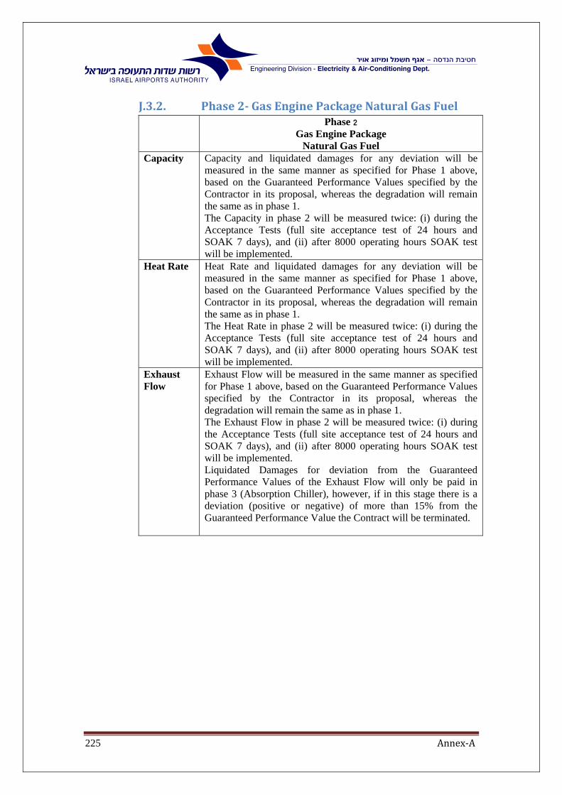
Annex‐A225
J.3.2. Phase2‐GasEnginePackageNaturalGasFuel Phase 2
Gas Engine Package Natural Gas Fuel
Capacity Capacity and liquidated damages for any deviation will be measured in the same manner as specified for Phase 1 above, based on the Guaranteed Performance Values specified by the Contractor in its proposal, whereas the degradation will remain the same as in phase 1. The Capacity in phase 2 will be measured twice: (i) during the Acceptance Tests (full site acceptance test of 24 hours and SOAK 7 days), and (ii) after 8000 operating hours SOAK test will be implemented.
Heat Rate Heat Rate and liquidated damages for any deviation will be measured in the same manner as specified for Phase 1 above, based on the Guaranteed Performance Values specified by the Contractor in its proposal, whereas the degradation will remain the same as in phase 1. The Heat Rate in phase 2 will be measured twice: (i) during the Acceptance Tests (full site acceptance test of 24 hours and SOAK 7 days), and (ii) after 8000 operating hours SOAK test will be implemented.
Exhaust Flow
Exhaust Flow will be measured in the same manner as specified for Phase 1 above, based on the Guaranteed Performance Values specified by the Contractor in its proposal, whereas the degradation will remain the same as in phase 1. The Exhaust Flow in phase 2 will be measured twice: (i) during the Acceptance Tests (full site acceptance test of 24 hours and SOAK 7 days), and (ii) after 8000 operating hours SOAK test will be implemented. Liquidated Damages for deviation from the Guaranteed Performance Values of the Exhaust Flow will only be paid in phase 3 (Absorption Chiller), however, if in this stage there is a deviation (positive or negative) of more than 15% from the Guaranteed Performance Value the Contract will be terminated.

Annex‐A226
J.3.3. Phase3‐IncludingChillerNaturalGasFuel
Phase 3
Including Chiller
Natural Gas Fuel Capacity Capacity and liquidated damages for any deviation will be measured in the same
manner as specified for Phase 1 above, based on the Guaranteed Performance Values specified by the Contractor in its proposal, whereas the degradation will remain the same as in phase 1. The Capacity in phase 3 will be measured twice: (i) during the Acceptance Tests (full site acceptance test of 24 hours and SOAK 7 days), and (ii) at the end of the Warranty Period (only 24 hours test will be implemented).
Chiller Capacity
Bidder will specify in its proposal the guaranteed Chiller Capacity and percentage of degradation (the "Guaranteed Performance Values") within the following range: Maximum (TON ref.) - 1500 Minimum (TON ref.) - 1300 Max degradation (%) – 2% per year. Chiller Capacity will be measured twice: (i) during the Acceptance Tests (full site acceptance test of 24 hours and SOAK 7 days), and (ii) at the end of the Warranty Period (only 24 hours test will be implemented). If during the Acceptance Test there is a negative deviation of up to 10% from the Guaranteed Performance Value, Contractor shall be required to pay Liquidated Damages of US$ 2,000 for each 1 ton ref. by which the chiller output demonstrated by the Plant is less than the Guaranteed Performance Values (the "Chiller Capacity Shortfall"). In the event that the negative deviation is of more than 10% from the Guaranteed Performance Values, then the Contract will be terminated. At the end of the Warranty Period, the Capacity will be measured again, but this time against the relevant Guaranteed Performance Value as adjusted based on the guaranteed degradation percentage that was specified by the Contractor (the "Adjusted Guaranteed Performance Value"). If there is negative deviation of up to 10% from the Adjusted Guaranteed Performance Value a, Contractor shall be required to pay Liquidated Damages of US$ 2,000 for each 1 ton ref. by which the chiller output demonstrated by the Plant is less than the Adjusted Guaranteed Performance Values. It is clarified, that the Contractor shall not be required to pay additional liquidated damages for the Chiller Capacity Shortfall that it had already paid for after the first measurement (if any), and the liquidated damages shall be calculated based on the difference between the previously measured Chiller Capacity value and the new value measured. In the event that the deviation is of more than 10% from the Adjusted Guaranteed Performance Values, then the Contract will be terminated. In any event, any deviation of the Chiller Capacity from the Minimum and Maximum values that were set by the IAA will cause termination of the Contract.
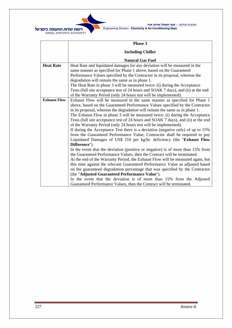
Annex‐A227
Phase 3
Including Chiller
Natural Gas Fuel Heat Rate Heat Rate and liquidated damages for any deviation will be measured in the
same manner as specified for Phase 1 above, based on the Guaranteed Performance Values specified by the Contractor in its proposal, whereas the degradation will remain the same as in phase 1. The Heat Rate in phase 3 will be measured twice: (i) during the Acceptance Tests (full site acceptance test of 24 hours and SOAK 7 days), and (ii) at the end of the Warranty Period (only 24 hours test will be implemented).
Exhaust Flow Exhaust Flow will be measured in the same manner as specified for Phase 1 above, based on the Guaranteed Performance Values specified by the Contractor in its proposal, whereas the degradation will remain the same as in phase 1. The Exhaust Flow in phase 3 will be measured twice: (i) during the Acceptance Tests (full site acceptance test of 24 hours and SOAK 7 days), and (ii) at the end of the Warranty Period (only 24 hours test will be implemented). If during the Acceptance Test there is a deviation (negative only) of up to 15% from the Guaranteed Performance Value, Contractor shall be required to pay Liquidated Damages of US$ 210 per kg/hr. deficiency (the "Exhaust Flow Difference"). In the event that the deviation (positive or negative) is of more than 15% from the Guaranteed Performance Values, then the Contract will be terminated. At the end of the Warranty Period, the Exhaust Flow will be measured again, but this time against the relevant Guaranteed Performance Value as adjusted based on the guaranteed degradation percentage that was specified by the Contractor (the "Adjusted Guaranteed Performance Value"). In the event that the deviation is of more than 15% from the Adjusted Guaranteed Performance Values, then the Contract will be terminated.

Annex‐A228
K. ChapterK‐. TenderGeneralForm
K.1. Guaranteedvalues
K.1.1. GeneralBidders should complete this Tender Form K1 in accordance Annex A chapter A
and C, and Appendix H, when doing so, Bidders must refer to Appendix J –
Tests Specifications and Penalties, referring to the requirements stipulated
herein.
The Guaranteed and Specified Performance Criteria should be stipulated in the
tables herein.
The Specified Performance Criteria values are the basis of the process design.
Those values are required for the evaluation of the proposals and for process
design quality and redundancy during the tender period. During the testing of
the Gas Engine Package, Specified Performance Criteria values will be used to
verify engine mechanical integrity, vibrations and compliance with acceptance
criteria performance levels.
Bidders should specify and provide the following curves for Prime Mover
Generator:
Power Output vs. Ambient Temperature
Heat Rate vs. Ambient Temperature
Power Output vs. Ambient Pressure
Heat Rate vs. Ambient Pressure
Power Output vs. Relative Humidity
Heat Rate vs. Relative Humidity
K.1.2. GuaranteedPerformanceFiguresThe Guaranteed Performance Figures provided by Bidders within this chapter k
will be checked and verified, in accordance with the tests specified in Appendix
J, during the various tests: the Shop Test (FAT) and, thereafter throughout the
24‐Hours Site Test and the SOAK‐ 7‐Days Site Test.
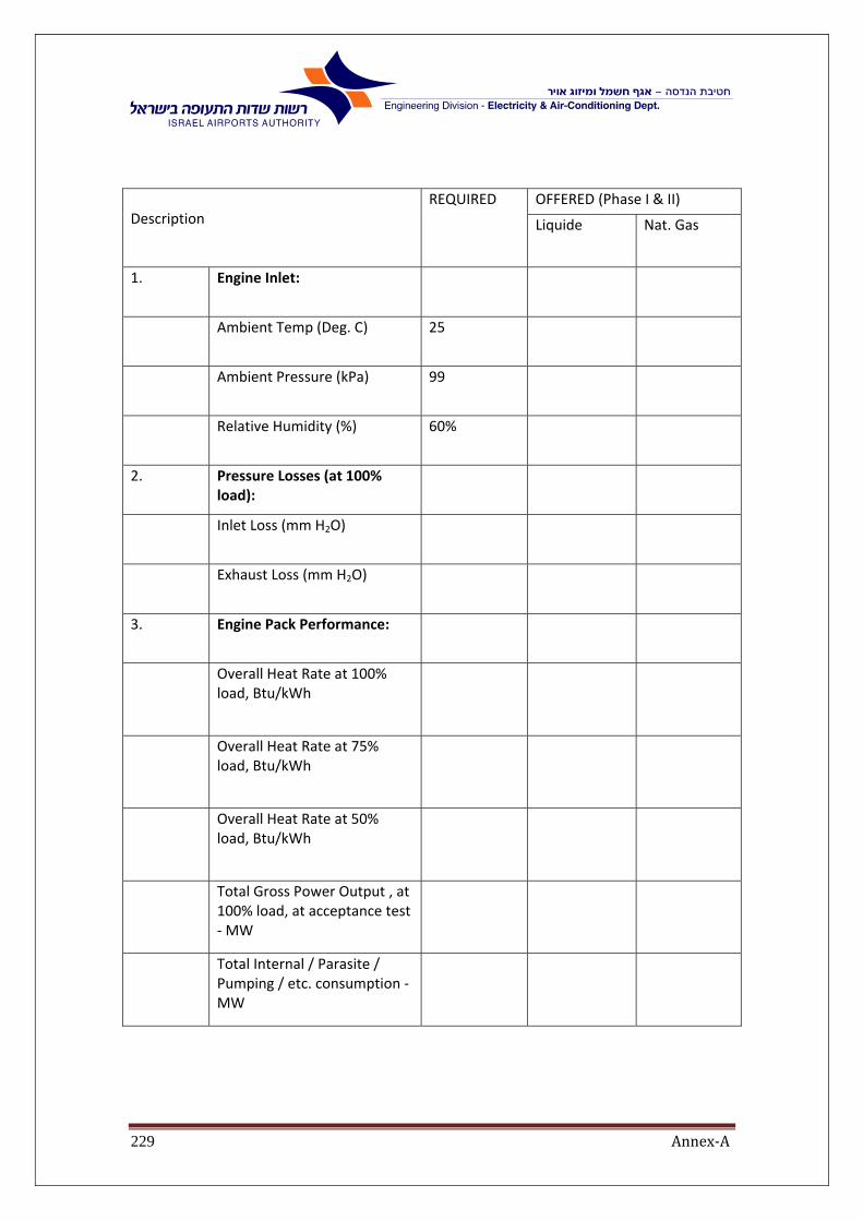
Annex‐A229
Description
REQUIRED
OFFERED (Phase I & II)
Liquide Nat. Gas
1. Engine Inlet:
Ambient Temp (Deg. C) 25
Ambient Pressure (kPa) 99
Relative Humidity (%) 60%
2. Pressure Losses (at 100% load):
Inlet Loss (mm H2O)
Exhaust Loss (mm H2O)
3. Engine Pack Performance:
Overall Heat Rate at 100% load, Btu/kWh
Overall Heat Rate at 75% load, Btu/kWh
Overall Heat Rate at 50% load, Btu/kWh
Total Gross Power Output , at 100% load, at acceptance test ‐ MW
Total Internal / Parasite / Pumping / etc. consumption ‐ MW

Annex‐A230
Description
REQUIRED
OFFERED (Phase I & II)
Liquide Nat. Gas
Net Overall Guarantied Power, at 100% load, at acceptance test ‐ MW
5.7 MW min.
Net Overall Guarantied Power, at 75% load, at acceptance test ‐ MW
Net Overall Guarantied Power, at 50% load, at acceptance test ‐ MW
Overall Power Plant Electrical Efficiency – at 100% load (%)
4. Engine Operation Data:
Exhaust manifold Flow Rate, at 100% load, kg/s
Exhaust manifold Temperature, at 100% load, Deg. C
Engine Gas Consumption, LHV ,at ISO condition, 100% load, Nm3/kWh
Engine Gross Power annual Degradation (%)
max/yr.
Engine Heat Rate annual Degradation (%)
max/yr.
Exhaust Flow Rate annual degradation (%)
max/yr.
Specific Oil Consumption, gr/kWh

Annex‐A231
Description
REQUIRED
OFFERED (Phase I & II)
Liquide Nat. Gas
5. Startup times from:
Cold conditions, sec.
Warm conditions, sec.
6. Availability:
Availability – First Year 92%
Availability ‐ Others 95%
7. Exhaust Gas Emissions:
SOx (mg/DSCM1) ‐‐‐
NOx (mg/DSCM1) 500
CO (mg/DSCM1) 300
NH3 (mg/DSCM1) 30
Formaldehyde(mg/DSCM1) 60

Annex‐A232
Description
REQUIRED
OFFERED (Phase III)
Liquide Nat. Gas
1. Engine Pack Performance including Chiller, at 100% load:
Net Overall Guarantied Power, at 100% load, at acceptance test ‐ MW
5.7 MW min.
Overall Heat Rate at 100% load, Btu/kWh
Chiller Capacity (TON ref.) 1,300 min.
Chiller Capacity annual Degradation (%)
max/yr.

Annex‐A233
K.2. TechnicalForm:Layoutandconstructionverificationandapproval
No Description Approve IAA
design
Contractor
Propose/Remarks
1 Building construction drawings
2 General arrangement drawing
2.1 Layout of Generator and future absorption
chiller, condenser, water, chilled water pumps
and piping
2.2 Generator's exhaust system layout
2.3 Indoor ventilation system
2.4 Roof mounted equipment layout
2.5 Cooling system layout
2.6 Hot water system Not in IAA drawing
2.7 Day tank
2.8 Compressed air system
2.9 Electrical equipment layout including:
MV switch board
LV switch board
MV transformer
UPS
Black start generator

Annex‐A234
K.3. EnvironmentalGeneratorThe following table presents the mandatory conditions for dry exhaust gas at
a temperature of 273 degrees Kelvin, a pressure of 101.3 kilopascal, and an
excess oxygen of 5 percent for Diesel generators (comply with T.A.Luft 2002)
and with appendix H:
For natural gas fuel:
Emission pollutant
Limit Value
T.A.Luft2002
Contractor
Approval
SOx (mg/DSCM1) ---
NOx (mg/DSCM1) 500
CO (mg/DSCM1) 300
NH3 (mg/DSCM1) 30
Formaldehyde(mg/DSCM1) 60
1‐ DSCM: Dry Standard Cubic Meter, 0 0C, 1atm @5%O2.

Annex‐A235
K.4. TECHNICALFORM:DIESELENGINEANDACCESSORIESNo Description Contractor
Propose/Remarks
1. General Information
1.1. Diesel engine manufacturer :
1.2. Type and Model No. :
1.3. Total weight of unit, Tones :
1.4. Basic type and rating at standard condition, HP/KW :
1.5. One line diagram
1.6. Heat and mass balance
1.7. P&I Drawing of the complete project
2. Rotation direction (viewed from Power take‐off end) :
3. Derating factors for altitude, % :
4. Derating factor for ambient temperature, % :
5. Engine Performance, at site condition :
5.1. Power output at 100% load (kW at site conditions)
5.2. Power generation (kW at generator output terminals)
5.3. Minimum Load (%)
5.4. Heat Rate (kJ/kWh, at site conditions and 25 Deg. C)
5.5. Gas Consumption (Nm3/kWh, at site conditions and 25 Deg. C)
5.6. Electrical Efficiency at 100% load, %
6. Operating speed, rpm ( max. 750 rpm) :
7. Number of strokes per cycle :
8. Arrangement of cylinders :
9. Number of cylinders :
10. Bore, mm :
11. Stroke, mm :
12. Swept volume, cc :
13. Compression ratio :
14. Maximum firing pressure, kg/sq.cm (g) :
15. Mean piston speed, rpm :
16. Brake mean effective pressure at rated load, kg/sq.cm (g) :
17. Mean indicated pressure at rated load, kg/sq.cm :
18. Firing order (viewed from power take off end), kg/sq.cm :
19. Maximum time required to start the engine from cold condition and to bring up to full speed, seconds :

Annex‐A236
No Description Contractor Propose/Remarks
20. Rate of loading per second after attaining full speed, KW/Sec. :
21. BSFC at :
21.1. 1/4 load, gm/kWh :
21.2. 1/2 load, gm/kWh :
21.3. 3/4 load, gm/kWh :
21.4. Full load, gm/kWh :
22. Lub oil temperature, inlet / outlet, Deg. C : /
23. Lub oil pressure, kg/sq.cm (g) :
24. Fuel oil pressure, kg/sq.cm (g) :
25. Water inlet/outlet temperature, Deg. C : /
26. Cyclic irregularity :
27. Recommended specification of fuel oil :
28. Governing :
29. Material of construction (Indicate) specific codes/standards) :
29.1. Cylinder :
29.2. Cylinder head :
29.3. Cylinder liners :
29.4. Crank shaft :
29.5. Connecting rod :
29.6. Piston :
29.7. Piston rings :
29.8. Gudgeon pin :
29.9. Inlet/exhaust valves :
29.10. Valve springs :
29.11. Heat exchanger :
29.11.1. Shell :
29.11.2. Tubes :
30. Protection Devices
30.1. High water temperature Deg. C :
30.2. Low lube oil pressure, kg/sq.cm(g) :
30.3. Overspeed, rpm
31. Lubricating Oil System

Annex‐A237
No Description Contractor Propose/Remarks
32. General Information
32.1. Type :
32.2. Minimum acceptable lub oil temperature at start up, Deg. C :
32.3. Lub oil consumption at rated load, gm/kWh :
32.4. Recommended specification of lubricating oil :
33. Engine Driven Lubricating Oil Pump
33.1. Type :
33.2. Number/engine :
33.3. Location :
33.4. Capacity, L/min. :
33.5. Drive rating, KW :
33.6. Discharge pressure, Kg/sq.cm. :
34. Motor Driven Lubricating Oil Pump (For priming/pre‐lubrication of lub oil circuit, if required)
34.1. Type :
34.2. Number/engine :
34.3. Location :
34.4. Capacity, L/min. :
34.5. Drive rating, kW :
34.6. Delivery pressure, kg/sq.cm. :
34.7. Materials of construction (Indicate applicable codes/ standards):
34.7.1. Casing :
34.7.2. Shaft :
35. Turbo‐Charger
35.1. Make :
35.2. Type :
35.3. Number/engine :
35.4. Speed, r.p.m. :
35.5. Charger air pressure at rated load, kg/sq.cm :
35.6. Material of construction (Indicate specific codes/ standards)
35.6.1. Turbine blade material :
35.6.2. Blower blade material :

Annex‐A238
No Description Contractor Propose/Remarks
36. After‐Cooler
36.1. Type :
36.2. Water flow, L/min. :
36.3. Water inlet temperature, Deg. C :
36.4. Water outlet temperature, Deg. C :
36.5. Free air flow, cu.m./hr. :
36.6. Inlet air pressure, kg/sq.cm :
36.7. Inlet air temperature, Deg. C :
36.8. Air temperature drop, Deg. C :
36.9. Material of construction :
37. Governing System
37.1. Type :
37.2. Make :
37.3. Steady state speed :
37.4. Steady state incremental speed regulation :
37.5. Prescribed speed band :
37.6. All other details of speed control arrangement :
37.7. Class of governing

Annex‐A239
K.4.1. TECHNICALFORM:COOLINGSYSTEMNo Description Contractor
Propose/Remarks
1. Engine Jacket Water Cooling
1.1. Type :
1.2. Engine jacket capacity :
1.3. Expansion tank/Head rank on radiator
1.3.1. Capacity of each tank, Litre :
1.3.2. Number :
1.3.3. Dimension, mm x mm :
1.3.4. Location :
1.4. Water pump
1.4.1. Type :
1.4.2. Number :
1.4.3. Capacity of each pump, L/min. :
1.4.4. Drive rating, kW :
1.4.5. Location :
1.5. Heat Exchanger ‐ Coolers
1.5.1. Type and make :
1.5.2. Number/engine :
1.5.3. Jacket water flow, L/min :
1.5.4. Inlet jacket water temperature, Deg.C :
1.5.5. Outlet jacket water temperature, Deg.C :
1.5.6. Cooling Water flow, L/min :
1.5.7. Design pressure for shell/tubes, Kg/sq.cm :
1.5.8. Hydro‐test pressure for shell/tubes, Kg/sq.cm :
1.5.9. Effective heat transfer area, Sq.M :
1.5.10. Number of plates per heat exchanger (including extra):
1.5.11. Gasket type & material :
1.5.12. Cleaning frequency of heat exchanger, hours:
1.5.13. Whether Cooler by‐pass line with control valve, provided ? :
Yes/No

Annex‐A240
No Description Contractor Propose/Remarks
2. Lub Oil Cooling
2.1. Type :
2.2. Engine lub‐oil capacity, Litres :
2.3. Lub‐oil cooling circulating pump
2.3.1. Type :
2.3.2. Number/engine :
2.3.3. Location :
2.3.4. Capacity, L/min. :
2.3.5. Delivery pressure, kg/sq.cm(g) :
2.3.6. Type of drive :
2.3.7. Drive rating, KW :
2.4. Lub‐oil HX cooler :
2.4.1. Type :
2.4.2. Number/engine :
2.4.3. Lub‐oil flow, L/min. :
2.4.4. Lub‐oil inlet temperature, Deg.C :
2.4.5. Lub‐oil outlet temperature from cooler, Deg.C:
2.4.6. Water inlet temperature to cooler, Deg.C :
2.4.7. Water outlet temperature from cooler, Deg.C:
2.4.8. Water flow, L/min :
2.4.9. Design pressure, kg/sq.cm(g) :
2.4.10. Test pressure, kg/sq.cm(g) :
2.4.11. Effective heat transfer area, sq.m :
2.4.12. Number of plates per heat exchanger (including extra):
2.4.13. Cleaning frequency, Hours :
2.5. Whether provided Lub‐oil by‐pass to cooler with control valve : Yes/No
3. Engine air intake filter
3.1. Type :
3.2. Manufactured by :
3.3. Pressure Drop across filter, at 100% load :
3.4. Free area :
3.5. Particle removing efficiency :

Annex‐A241
No Description Contractor Propose/Remarks
4. Fan cooled Radiators
4.1. Type :
4.2. Make :
4.3. Location :
4.4. Water inlet temperature, Deg. C :
4.5. Water outlet temperature, Deg. C :
4.6. Cooling air flow, cu.m./hr :
4.7. Total cooling surface area, sq.m. :
4.8. Material of construction (Indicate specific codes /standard)
4.8.1. Tubes :
4.8.2. Fins :
4.8.3. Header :
5. Cooling Fan
5.1. Type :
5.2. Number :
5.3. Location :
5.4. Capacity of each fan, N.cu.m/hr :
5.5. Power installed for each fan, kW :
5.6. Maximum power consumption of cooling air fan at MCR of
generator at rated operating condition, kW :
5.7. Fan speed, r.p.m. :
5.8. Total cooling surface area, sq.m. :
5.9. Material of construction (Indicate applicable codes/standards)
6. Total cooling water required per engine, Cu.M/Hr :
7. Cooling water make up required per engine, Cu.M/Hr (To be provided by the owner):
8. Total auxiliary power supply required for the cooling system: KVA/Amps/Voltage
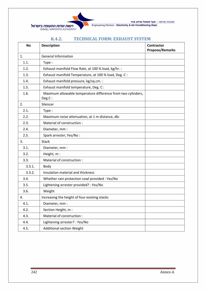
Annex‐A242
K.4.2. TECHNICALFORM:EXHAUSTSYSTEMNo Description Contractor
Propose/Remarks
1. General Information
1.1. Type :
1.2. Exhaust manifold Flow Rate, at 100 % load, kg/hr. :
1.3. Exhaust manifold Temperature, at 100 % load, Deg. C :
1.4. Exhaust manifold pressure, kg/sq.cm. :
1.5. Exhaust manifold temperature, Deg. C :
1.6. Maximum allowable temperature difference from two cylinders, Deg.C :
2. Silencer
2.1. Type :
2.2. Maximum noise attenuation, at 1 m distance, db:
2.3. Material of construction :
2.4. Diameter, mm :
2.5. Spark arrester, Yes/No :
3. Stack
3.1. Diameter, mm :
3.2. Height, m :
3.3. Material of construction :
3.3.1. Body
3.3.2. Insulation material and thickness
3.4. Whether rain protection cowl provided : Yes/No
3.5. Lightening arrester provided? : Yes/No
3.6. Weight
4. Increasing the height of four existing stacks
4.1. Diameter, mm :
4.2. Section Height, m :
4.3. Material of construction :
4.4. Lightening arrester? : Yes/No
4.5. Additional section Weight

Annex‐A243
K.4.3. TECHNICALFORM:GENSETUNIT1. Generator Description:
Manufacturer:
Model Number:
2. Prime Mover Description: Diesel Engine for dual fuel operation, namely both, light fuel oil #2 and natural gas.
Manufacturer:
Model Number:
Unit Description and Technology:
No Description Contractor Propose/Remarks
PF Rated Power Factor
Un Rated Voltage [kV]
Fn Rated Frequency [Hz]
Pmax Maximum generating capacity of Prime Mover [MW]
Pmin Minimum generating power of Prime Mover [MW]
Paux Total auxiliary power load demand [MW]
n‐g Rated Generator Shaft Speed [rpm]
n‐gt Rated Prime Mover Shaft Speed [rpm]
p Number of Poles Pairs
Moment of inertia of Generator [kgm2]
I Moment of inertia of Prime Mover [kgm2]
Moment of inertia of Gearbox and Coupling (if exists) [kgm2]
H Total Inertia Constant (Generator, Prime mover, etc.) [MWs/MVA]
Xd Direct Axis Synchronous Reactance [pu] saturated
unsaturated
Xq Quadrature Axis Synchronous Reactance [pu] saturated
unsaturated
Xd’ Direct Axis Synchronous Reactance [pu] saturated
unsaturated
Xq’ Quadrature Axis Synchronous Reactance [pu] saturated
unsaturated
Xd” Direct Axis Synchronous Reactance [pu] saturated
unsaturated no less than 0.2pu
Xq” Quadrature Axis Synchronous Reactance [pu] saturated
unsaturated

Annex‐A244
No Description Contractor Propose/Remarks
Xl Stator Leakage Reactance [pu]
Tdo' Direct Axis Transient Open Circuit Time Constant [sec] at ___oC
Tqo' Quadrature Axis Transient Open Circuit Time Constant [sec] at ___oC
Tdo" Direct Axis Subtransient Open Circuit Time Constant [sec] at ___oC
Tqo" Quadrature Axis Subtransient Open Circuit Constant [sec] at ___oC
Td' Direct Axis Transient Time Constant [sec] at ___oC
Tq' Quadrature Axis Transient Time Constant [sec] at ___oC
Td" Direct Axis Subtransient Time Constant [sec] at ___oC
Tq" Quadrature Axis Subtransient Time Constant [sec] at ___oC
Ta Stator Time Constant [sec] at ___oC
Ra Stator Resistance [ohm] at ___oC
Rf Field Winding Resistance [ohm] at ___oC
R0 Zero Sequence Resistance [ohm] at ___oC
X0 Zero Sequence Reactance [pu]
R(damp) Dampers Resistance [ohm] at ___oC
L(damp) Dampers Inductance [H]
R2 Negative Sequence Resistance [ohm] at ___oC
X2 Negative Sequence Reactance [pu]
Cph Phase earth capacitance [µF]
XP Potier reactance [pu]
SCR Short Circuit Ratio
S Saturation Factors: ‐ S(1.0)
‐ S(1.2)
1 Continuous unbalanced load, maximum I2∞ [pu]
2 Short time capability for unbal. faults, max. I22 *t [pu]*s
3 Voltage increase at sudden load rejection and rated cosφ = 0.85
(without AVR action) [%]
4 Voltage increase at sudden load rejection and rated cosφ = 1
(without AVR action) [%]
5 3‐phase short‐circuit current (peak value) [kA]
6 3‐phase short‐circuit current (RMS value) [kA]

Annex‐A245
No Description Contractor Propose/Remarks
Generator diagrams:
1 Calculated Capability Curve P‐Q
2 Generator Power versus Ambient Temperature Curve
3 Saturation Curves (Air Gap Line, No Load Saturation, SC Saturation)
4 Unbalanced load curves
5 Generator Losses curves
5 Generator Efficiency curves
6 V ‐ Curves
7 Excitation System
Block Diagram: Excitation system block diagram and parameters values, preferably in accordance with one of the commonly used transient‐midterm‐longterm stability computer programs, such as PSS/E (PTI).
8 Turbine and Speed Governor
Block Diagram: Turbine and Speed Governor system block diagram and
parameters values, preferably in accordance with one of the commonly used
stability computer programs, such as PSS/E (PTI).
9 Power Stabilizer System : Block Diagram: Stabilizer block diagram and parameters values, preferably in accordance with one of the commonly used stability computer programs, such as PSS/E (PTI).
10 Additional Models
Block diagrams and parameters values for additional models, such as for
Minimum Excitation Limiter, Maximum Excitation Limiter, preferably in
accordance with one of the commonly used stability computer programs,
such as PSS/E (PTI).

Annex‐A246
K.5. EquipmentQuestionnaireThe “required” column in the tables (if used) displays minimum requirements.
The bidder must fill all data in the “offered” column displaying equal or better properties to the required
.
K.5.1. StepupMVtransformer
Power Transformer: Manufacturer Data/Remarks
Manufacturer/country
Power rating based on the temperature conditions indicated in the spec.
Transformer rated power :
ONAN (MVA) at 55C rise
ONAF (MVA) at 55C rise
ONAN (MVA) at 65C rise
ONAF (MVA) at 65C rise
Is the transformer capable of operating at these ratings
(65C) continuously without loss of life? ......................(yes or no)
Annex‐A247
Tap‐changer: Manufacturer Data/Remarks
At principal tap (kV/kV)
At maximum tap (kV/kV)
At minimum tap (kV/kV)
Number of taps above principal (‐%Tap)
Number of taps below principal (+%Tap)
Taps position mechanical indication
Impedance:
Positive sequence
Zero sequence
Measured between high voltage (22kV) and low voltage winding 11kV) terminals (%)
Impedance for extreme positions of tap‐changer
Max. tap (%)
Min. tap (%)
Tolerance (+%)
Bushing current transformer Bushing CTs for thermal image
Bushing CT for LV Neutral
Overload capability of the bushings:
Maximum permissible overload of the bushing CTs (A)
The bushing CTs hottest‐spot temperature, above the temperature of the immersion medium in overload conditions (C)
Duration (s)
Temperature rise of the hottest spot of the current carrying parts, above the temperature of the immersion medium in rated conditions(C)
Rated short‐time current 1 sec. (kA)
Rated short‐time current 2 sec. (kA)
Dynamic short‐circuit withstand current (kA)

Annex‐A248
Insulation: Offered
Insulation levels of winding dielectric test:
High voltage winding
Low voltage neutral terminal
Low voltage winding
Insulation class (kV)
Rated withstand voltage of the windings
Rated lightning impulse withstand
voltage 1.2/50 sec (kV peak)
Rated short duration power frequency withstand voltage (kV rms)
Dielectric strength:
High voltage Low voltage
Lightning impulse test
Full impulse wave test voltage (kV peak)
Full chopped impulse wave test voltage (kV peak)
Minimum time to copping (sec)
Full impulse wave test voltage for neutral terminal (kV peak)
Separate source voltage withstand test (kV rms)
Induced voltage test (kV rms)

Annex‐A249
Subject: (MVA base shall be revised according to proposed generator ratings)
Manufacturer Data/Remarks
Losses (guaranteed):
No load loss (excitation loss)
Load loss (at 10MVA):
At principal tap (kW)
At maximum tap (kW)
At minimum tap (kW)
Total loss excluding auxiliary power at 10MVA (no load plus load loss with 10MVA loading of the low voltage winding at principal tap (kW)
Auxiliary power (total requirements for future cooling):
At 10 MVA (guaranteed) (kW)
At 7 MVA (kW)
Guaranteed efficiency (not including power for cooling) at 0.85 power factor and 22/11kV:
Full load (10MVA) (%)
3/4 LOAD (%)
1/2 LOAD (%)
1/4 LOAD (%)
Guaranteed regulation (H winding to X winding with rated MVA on X winding
Unity power factor (%)
0.8 power factor (%)
Exciting current (guaranteed) ‐ referred to 10MVA
Inrush RMS magnetizing current with no residual magnetism at 11.5kV (times full load current)
Permissible short‐time power frequency over‐voltage of the transformer, at no‐load, stating from full‐load temperature:
At 135% over‐voltage
sec
At 130% over‐voltage
sec
At 125% over‐voltage
sec

Annex‐A250
Subject: (MVA base shall be revised according to proposed generator ratings)
Manufacturer Data/Remarks
At 120% over‐voltage
Sec
At 115% over‐voltage
min
At 110% over‐voltage
min
High voltage winding (ohms)
Low voltage winding (ohms)
Temperature rise at 10MVA of:
Winding (guaranteed) measured by resistance (C)
Hottest spot (C)
Top of oil (C)
Per cent capacity reduction with one cooler out of service (%)
Estimated time that transformer can carry full load, without damage, with fans out of service under the following conditions:
Starting cold (hours)
After operating continuously at full load (hours)
Average sound level according to NEMA at 22kV:
Immediately near the transformer (dBA)
50 Meters from the transformer (dBA)
100 Meters from the transformer (dBA)
Average sound level according to NEMA at 22kV when operating at no load (11MVA) with cooing in operating:
Immediately near the transformer (dBA)
50 Meters from the transformer (dBA)
100 Meters from the transformer (dBA)

Annex‐A251
K.5.2. TECHNICALFORMMV1600/400kVAtransformersinformation
Description Manufacturer Data/Remarks
Manufacturer
Country of origin
Performance Data:
Transformer rated power at 55C rise (KVA):
Transformer rated power at 60C rise for continuous operation without loss of life (kVA):
Highest primary system voltage (kV)
System primary neutral
System secondary neutral
Transformer connection group
Rated voltage of primary winding (kV)
Rated voltage of secondary winding (kV)
Rated lightning impulse withstands voltage.
Sound pressure levels at 1m
K factor
Short circuit impedance voltage:
Uk%
Ur%
Ux%
Load losses: (kW)
Annex‐A252
Description Manufacturer Data/Remarks
No load losses: (kW)
Oil:
Oil Type
Oil igniting temperature (C)
OFF load tap‐changer:
Full capacity is required for the entire range of voltage
regulation
Number of taps
Voltage range (%)
Rated step voltage (kV)
At principal tap (‘O’ position), transformer ratio shall be:
Bushings and terminals:
Nominal voltage for HV plug‐in bushing
Rated withstand voltage for HV plug‐in bushing kV
Rated lighting impulse withstand peak voltage(BIL)
Creepage distance LV side: (mm)
Air clearance to earth LV side: (mm
Maximum permissible overload of the HV bushing (A)
Maximum permissible overload of the LV bushing (A)
The bushing hottest‐spot temperature, above the
temperature of the immersion medium in overload
conditions (C)
Temperature rise of the hottest spot of the current
carrying parts, above the temperature of the immersion
medium in rated conditions(C)

Annex‐A253
Description Manufacturer Data/Remarks
Temperature rise of HV current carrying parts during
short‐circuit (1 sec. with rated short time current (C)
Temperature rise of LV current carrying parts during
short‐circuit (1 sec. with rated short time current (C)
Diameter of the HV conductor (mm)
Diameter of the LV conductor (mm)
Cross sectional area of the MV conductor (mm2)
Cross sectional area of the LV conductor (mm2)
Dimensions and weights:
Total weight (Kg)
Oil weight (Kg)
Dimensions: W x H x D (Max)
Skid type
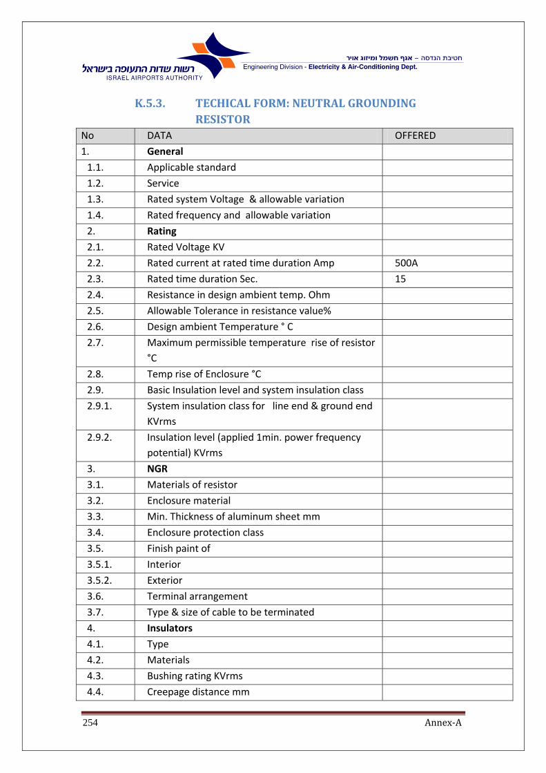
Annex‐A254
K.5.3. TECHICALFORM:NEUTRALGROUNDINGRESISTOR
No DATA OFFERED
1. General
1.1. Applicable standard
1.2. Service
1.3. Rated system Voltage & allowable variation
1.4. Rated frequency and allowable variation
2. Rating
2.1. Rated Voltage KV
2.2. Rated current at rated time duration Amp 500A
2.3. Rated time duration Sec. 15
2.4. Resistance in design ambient temp. Ohm
2.5. Allowable Tolerance in resistance value%
2.6. Design ambient Temperature ° C
2.7. Maximum permissible temperature rise of resistor
°C
2.8. Temp rise of Enclosure °C
2.9. Basic Insulation level and system insulation class
2.9.1. System insulation class for line end & ground end
KVrms
2.9.2. Insulation level (applied 1min. power frequency
potential) KVrms
3. NGR
3.1. Materials of resistor
3.2. Enclosure material
3.3. Min. Thickness of aluminum sheet mm
3.4. Enclosure protection class
3.5. Finish paint of
3.5.1. Interior
3.5.2. Exterior
3.6. Terminal arrangement
3.7. Type & size of cable to be terminated
4. Insulators
4.1. Type
4.2. Materials
4.3. Bushing rating KVrms
4.4. Creepage distance mm

Annex‐A255
K.5.4. TECHNICALFORM:22Kv‐MVenclosure
Required Offered
1. Manufacturer ‐
2. Country of production ‐
3. Production quality supervision ISO 9002
4. Prototype tested at (laboratory name
and date of test)
ISO 9002
5. Dimensions (maximum)
Height (cm)
Width (cm)
Depth (cm)
6. Bus Bars ‐ type
material
Current (In)
Short circuit capacity
Insulated
copper
2000A
25kA
7. Back and front access doors with
handle and padlock attachment
(Yes/No)
8. Control selector switch with visual
switching position indicator
9. R.S.T indication lamps with capacitor
(Yes/No)
10. Emergency push button type
11. Heating elements, quantity, capacity
and type
12. Enclosure lighting PL9/IP44 limit
switch operated type

Annex‐A256
Required Offered
13. Control relays
14. Indication lamps 22 mm diameter,
manufacturer and type
15. Control terminals
16. Miniature circuit breakers (10KA)
17. Timers (manufacturer and type)
18. Mimic diagram ‐ colored Aluminum
strips and figures (Yes/No)
19. Current/voltage/power, power factor
4‐20mA converters (manufacturer and
type)
20. Pressure release upper vent (Yes/No)
21. Local measuring instruments for
current, voltage and power factor
96X96mm (manufacturer and type)
22. Rated voltage 24kV
23. Insulation
1 min/50Hz/kV RMS
50kV
24. Peak insulation level 1.2/50s 125kV
25. Short time withstand current (3sec) 25kA RMS
26. Peak withstand current 63kA

Annex‐A257
K.5.5. TECHNICALFORM:11Kv‐MVenclosure Required Offered
1. Manufacturer ‐
2. Country of production ‐
3. Production quality supervision ISO 9002
4. Prototype tested at (laboratory name
and date of test)
ISO 9002
5. Dimensions (maximum)
Height (cm)
Width (cm)
Depth (cm)
240
100
200
6. Bus Bars ‐ type
material
Current (In)
Short circuit capacity
Insulated
copper
2000A
31.5kA
7. Back and front access doors with
handle and padlock attachment
(Yes/No)
8. Control selector switch with visual
switching position indicator
9. R.S.T indication lamps with capacitor
(Yes/No)
10. Emergency push button type
11. Heating elements, quantity, capacity
and type
12. Enclosure lighting PL9/IP44 limit
switch operated type
13.

Annex‐A258
Required Offered
14. Indication lamps 22 mm diameter,
manufacturer and type
15. Control terminals
16. Miniature circuit breakers (10KA)
17. Timers (manufacturer and type)
18. Mimic diagram ‐ coloured Aluminum
strips and figures (Yes/No)
19. Current/voltage/power, power factor
4‐20mA converters (manufacturer and
type)
20. Pressure release upper vent (Yes/No)
21. Local measuring instruments for
current, voltage and power factor
96X96mm (manufacturer and type)
22. Surface treatment
‐ Outside panels acc. to (galvanized +
epoxy polyester coating)
‐ Internal partitions
IEC 60068‐2‐11
Galvanized with
chrome passivation
23. Rated voltage 12kV
24. Insulation
1 min/50Hz/kV RMS
28kV
25. Peak insulation level 1.2/50s 75kV
26. Short time withstand current (3sec) 31.5kA RMS
27. Peak withstand current 80kA

Annex‐A259
K.5.6. TECHNICALFORM:MVCircuitBreaker Description REQUIRED OFFERED
12 kV 22kV
1. Manufacturer
2. Type
3. Rated voltage (kV) 12/24
4. Rated insulation level:
5. Impulse withstand
voltage:
‐ to earth, between
poles and across open
switchgear device (kV)
‐ across the isolating
distance (kV)
6. One‐minute power
frequency withstand
voltage:
‐ to earth, between
poles and across open
switching device (kV)
‐ across the isolating
distance (kV)
7. Rated frequency (Hz) 50
8. Rated current of main
22kV breakers (A)
2000A ‐
9. Rated current of
secondary 22kV
breakers (A)
800A ‐

Annex‐A260
Description REQUIRED OFFERED
12 kV 22kV
10. Rated current of main
12kV breakers (A)
2000A ‐
11. Rated current of
secondary 12kV
breakers
1600A ‐
12. Rated short time
withstand current Ith
(kA/3 sec)
13. Rated peak withstand
current (kA)
14. Rated breaking capacity
15. At 12kV (KA) 31.5 ‐
16. At 24kV (KA) 25 ‐
17. Note: with operating
sequence 0‐3min‐co‐
3min‐co and 0‐0.35‐co‐
15S‐co
18. Rated short circuit
making capacity (kA)
19. Rated breaking
capacities for on‐load
isolator
20. SF6 gas:
21. Rated filling pressure
22. Minimum functional
pressure

Annex‐A261
Description REQUIRED OFFERED
12 kV 22kV
23. Volume of gas used in
the SF6 switchgear
24. Internal fault withstand
for 1 sec (kA)
25. Maximum permissible
partial discharge
quantity at 1.1 Un (pC)
26. Technical
characteristics for
motor drive:
27. Rated voltage (V) 220VDC
28. Maximum continuous
current (A)
29. Maximum inrush
current (A) for a
maximum duration of
(sec)
30. Maximum no. of
operations (close‐open)
(no.)
31. Quality assurance
system
ISO 9001
32. Standard
33. Operating time
34. Opening time (msec)
35. Arcing time (msec)
36. Break time (msec)

Annex‐A262
Description REQUIRED OFFERED
12 kV 22kV
37. Closing time (msec)
38. Gas
39. Rated pressure at 20C (kPa)
40. Number of gas pressure
indication lamps
3
41. Operating mechanism
42. Removable manual
spring charging lever
(yes/no)
43. Manual closing push
button (yes/no)
44. Manual opening push
button (yes/no)
45. Key lock/interlock
(yes/no)
46. Indicator lamp for
ON/OFF positions
(yes/no)
47. Value for SF6 gas filling
(yes/no)
48. Indicator for
charged/discharged
spring condition
49. Operation counter Y/N
50. Breaker enclosure
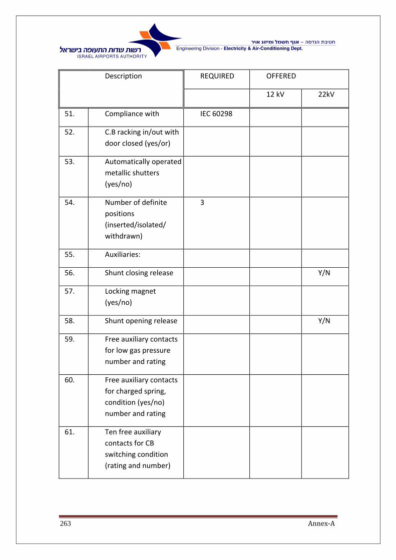
Annex‐A263
Description REQUIRED OFFERED
12 kV 22kV
51. Compliance with IEC 60298
52. C.B racking in/out with
door closed (yes/or)
53. Automatically operated
metallic shutters
(yes/no)
54. Number of definite
positions
(inserted/isolated/
withdrawn)
3
55. Auxiliaries:
56. Shunt closing release Y/N
57. Locking magnet
(yes/no)
58. Shunt opening release Y/N
59. Free auxiliary contacts
for low gas pressure
number and rating
60. Free auxiliary contacts
for charged spring,
condition (yes/no)
number and rating
61. Ten free auxiliary
contacts for CB
switching condition
(rating and number)
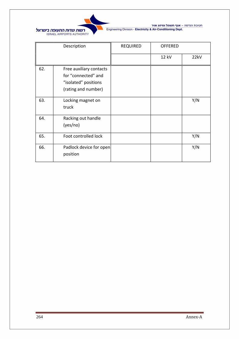
Annex‐A264
Description REQUIRED OFFERED
12 kV 22kV
62. Free auxiliary contacts
for “connected” and
“isolated” positions
(rating and number)
63. Locking magnet on
truck
Y/N
64. Racking out handle
(yes/no)
65. Foot controlled lock Y/N
66. Padlock device for open
position
Y/N

Annex‐A265
K.5.7. TECHNICALFORM:MVCurrentTransformers Required Offered
1. Manufacturer/type
2. Country
3. Copper
4. Hot cast insulating resin under vacuum (yes/or)
5. Core materials
‐ Nickel iron (75% NI) for measuring cores
‐ mill patterned cold rolled silicon iron for protection cores
yes/no
6. Standard: IEC 185 (1987) yes/no
7. Insulation level:
for 11kV systems
for 22kV systems
17.5kV
24kV
8. Insulation Impulse test (BIL)
‐ for 11kV C.T
‐ for 24kV C.T
95kV
125kV
9. Current error for class 5P at rated primary current
1%
10. Composite error at error limit factor
5%
11. Terminal identification and information on name plate
yes/no
12. Dielectric routine tests yes/no
13. Inter‐turn test yes/no
14. Accuracy tests yes/no
15. Partial discharge test yes/no
16. Polarity test yes/no
17. Type tests yes/no

Annex‐A266
K.5.8. MVPotentialTransformers required offered
C.1 Manufacturer/type
C.2 Country
C.3 Hot cast insulating resin under vacuum
yes/no
C.4 Standard IEC
C.5 Voltage factor for line to ground units
‐ for grounded neutral
‐ for impedance neutral
1.5Un‐30sec
1.9Un‐30sec.
C.6 Voltage factor for line to line units (conditions)
1.2Un
C.7 Insulation Impulse test (BIL)
‐ for 11kV P.T
‐ for 24kV P.T
95kV
125kV