Embed Size (px)
Citation preview

IALA VDES WG3
Working document
Annex 4
Technical characteristics of VDES-satellite downlink
in the maritime mobile band
1. Introduction
This Annex describes the characteristics of the satellite downlink of the VHF Data Exchange System (VDES) according to the identified requirements.
In particular, VDE Satellite Downlink is assumed to support the following services:
Downlink multicast multi-packet data transfer; Shore originated unicast multi-packet data transfer via satellite.
In this Annex, Low Earth Orbit (LEO) satellites with 600 km altitude are considered to present typical examples of VDE Satellite Downlink solutions. It should be noted that other orbital selections are also possible according to the overall system design consideration.
2. OSI Layers This Annex describes the four lower layers of the OSI model; the physical, the link, the network and the transport layers as shown in Figure 1.
Figure 1. Seven layer OSI model
2.1 Responsibilities of the OSI layers for preparing VDE data for transmission 2.1.1 Transport layer This layer ensures reliable transmission of the data segments between a ship
and a satellite, including segmentation, acknowledgement and multiplexing.

2.1.2 Network layer This layer is responsible for the management of priority assignments of messages, distribution of transmission packets between channels, and data link congestion resolution.
2.1.3 Link layer This layer ensures reliable transmission of data frames between a satellite and
a ship. The link layer is divided into three sub-layers with the following tasks: 2.1.3.1 Link management entity
Assemble unique word, format header, pilot tones, subframe headers and VDES message bits into packets.
2.1.3.2 Data link services Applies bit stuffing (if required), calculates and adds CRC check sum and
completes the subframe/packet. 2.1.3.3 Media Access Control Provides methods for granting data transfer access. Both random access and
assigned access are used. 2.1.4 Physical layer This layer provides transmission and reception of raw bit streams over a physical medium including signal modulation, filtering/shaping upon transmission, and amplification, filtering, time and frequency synchronization, demodulation, and decoding upon reception.
3. Physical layer 3.1 Range (minimum and maximum) The orbit height determines the satellite range variations. For example, for a 600 km LEO the maximum range is 2830 km. For timing purposes a maximum range of 3000 km will be used The minimum range is equal to the orbit height. For a LEO satellite at 300 km altitude the minimum range will be 300 km. This value is used to determine the minimum propagation delay time. Considering these exemplary values for the minimum and maximum ranges, the path delay will vary from 10 ms to 1 ms, a variation of 9 ms as shown in Figure 2. In addition to the relative delays between signal receptions at a vessel from different satellites, there could be absolute delay due to other sources. The satellite service provider should pre-compensate for absolute delay.
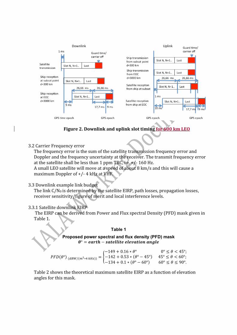
Figure 2. Downlink and uplink slot timing for 600 km LEO 3.2 Carrier Frequency error The frequency error is the sum of the satellite transmission frequency error and
Doppler and the frequency uncertainty at the receiver. The transmit frequency error at the satellite shall be less than 1 ppm TBC, i.e. +/- 160 Hz.
A small LEO satellite will move at a speed of about 8 km/s and this will cause a maximum Doppler of +/- 4 kHz at VHF.
3.3 Downlink example link budget The link C/N0 is determined by the satellite EIRP, path losses, propagation losses,
receiver sensitivity/figure of merit and local interference levels. 3.3.1 Satellite downlink EIRP The EIRP can be derived from Power and Flux spectral Density (PFD) mask given in
Table 1.
Table 1
Proposed power spectral and flux density (PFD) mask 𝜽° = 𝒆𝒂𝒓𝒕𝒉 − 𝒔𝒂𝒕𝒆𝒍𝒍𝒊𝒕𝒆 𝒆𝒍𝒆𝒗𝒂𝒕𝒊𝒐𝒏 𝒂𝒏𝒈𝒍𝒆
𝑃𝐹𝐷(𝜃°) (𝑑𝐵𝑊/(𝑚2∗4 𝑘𝐻𝑧)) = {
−149 + 0.16 ∗ 𝜃° 0° ≤ 𝜃 < 45°;−142 + 0.53 ∗ (𝜃° − 45°) 45° ≤ 𝜃 < 60°;
−134 + 0.1 ∗ (𝜃° − 60°) 60° ≤ 𝜃 ≤ 90°.
Table 2 shows the theoretical maximum satellite EIRP as a function of elevation angles for this mask.

Table 2. Satellite maximum EIRP vs. elevation angle.
Elevation
angle 𝜃
Powerflux density on
ground
Satellite range
Maximum downlink
satellite EIRP
(degrees) (dBW/m2/4 kHz) (km) (dBW in 25 kHz)
0 -149,0 2831 -1,0
10 -147,4 1932 -2,7
20 -145,8 1392 -4,0
30 -144,2 1075 -4,6
40 -142,6 882 -4,7
50 -139,4 761 -2,8
60 -134,0 683 1,6
70 -133,0 635 2,0
80 -132,0 608 2,6
90 -131,0 600 3,5
3.3.2 Example satellite EIRP vs. elevation Most of the satellite coverage area and visibility time will be at low elevation angles,
and high elevation angle coverage may be sacrificed without significant system capacity loss.
The example link budget is optimised for 0 degrees ship elevation angle using a three
element Yagi antenna at the satellite pointed at the horizon is given in Table 3. Assuming a peak antenna gain of 8 dBi, a transmit RF power of -12,4 dBW in 25 kHz
will ensure compliance with the PFD limit. Example satellite EIRP vs. ship elevation is shown in Table 3.

Table 3. Example satellite EIRP vs. elevation using a Yagi antenna
Yagi antenna
Ship elevation
angle
Nadir offset angle
Boresight offset
Satellite antenna
gain
Satellite EIRP in circular
polarization Satellite
range PFD Table 1
PFD limit PFD
margin
degrees degrees degrees dBi dBW km dBW/m2/
4 kHz dBW/m2/
4 kHz dB
0 66,1 0 8 -4,4 2830 -152,4 -149,0 3,4
10 64,2 1,9 8 -4,4 1932 -149,1 -147,4 1,7
20 59,2 6,9 8 -4,4 1392 -146,2 -145,8 0,4
30 52,3 13,8 7,8 -4,6 1075 -144,2 -144,2 0,0
40 44,4 21,7 6,9 -5,5 882 -143,4 -142,6 0,8
50 36 30,1 5,5 -6,9 761 -143,5 -139,4 4,1
60 27,2 38,9 3,6 -8,8 683 -144,5 -134,0 10,5
70 18,2 47,9 0,7 -11,7 635 -146,7 -133,0 13,7
80 9,1 57 -2,2 -14,6 608 -149,2 -132,0 17,2
90 0 66,1 -5,5 -17,9 600 -152,4 -131,0 21,4
3.3.3 Receive antenna gain Existing ship antennas shall be used for VDES. The maximum antenna gain for
these range from 2 to 10 dBi with respect to a vertically polarized reference antenna. Representative antenna patterns are shown in Figure 3.
A ship antenna with a minimum gain at 0 degrees elevation of 3 dBi at the receiver input is required. The antenna gain and noise level can be traded as long as the sum of the two exceeds -113 dBm.

Figure 3. Ship antenna gain vs. elevation angle.
3.3.4 Received signal to noise plus interference level The noise floor is a function of many sources such as vessel electronics, other
radio equipment, power supplies, etc., and sensitivity is also reduced by RF cabling losses, LNA noise figure. The downlink assumes an expected equivalent noise and interference level that is less than - 116 dBm/25 kHz at the receiver input.
3.3.5 Link C/(N0+I0) The nominal signal level and C/(N0+I0) vs. elevation for a 25 kHz channel is given in Table 4. The signal level and C/(N0+I0) increase 3 dB for 50 kHz channels and 6 dB for 100 kHz wide channels respectively. High elevation coverage applies to few satellite passes, and only for a short period, and system operator may select the operational elevation range. The nominal downlink C/(N0+I0) is 41 to 47 dBHz for ship elevation angles between 0 and 65 degrees in a 25 kHz channel.
The maximum PFD from the satellite transmissions in 4 KHz bandwidth is the same as calculated above and in Table 3, however the increased channel and modulated signal bandwidth increase the maximum transmitted total RF power by the increased bandwidth ratio, i.e. 3 and 6 dB for the 50 and 100 kHz channels over than of a single 25 kHz channel. It should also be noted that the analyses based on single satellite visibility.
-15
-10
-5
0
5
10
0 20 40 60 80
Gain (dBi)
Elevation angle (degrees)
VHF ship antenna gain vs elevation angle
2 dBi
3 dBi
6 dBi
9 dBi

Table 4. Nominal link budget vs. ship elevation for a 25 kHz channel.
Ship elevation
angle
Satellite EIRP
in circular polarization
Satellite range Pathloss
Polarization loss
Ship antenna
gain
Antenna signal level
Noise level in 25
kHz BW C/(N0+I0)
degrees dBW km dB dB dBi dBm dBm dBHz
0 -4,4 2830 144,6 3 3 -119,0 -116 41,0
10 -4,4 1932 141,2 3 3 -115,7 -116 44,3
20 -4,4 1392 138,4 3 2,5 -113,3 -116 46,7
30 -4,6 1075 136,2 3 1 -112,8 -116 47,2
40 -5,5 882 134,4 3 0 -113,0 -116 47,0
50 -6,9 761 133,2 3 -1,5 -114,6 -116 45,4
60 -8,8 683 132,2 3 -3 -117,0 -116 42,9
70 -11,7 635 131,6 3 -4 -120,3 -116 39,7
80 -14,6 608 131,2 3 -10 -128,8 -116 31,2
90 -17,9 600 131,1 3 -20 -142,0 -116 18,0
3.4 Propagation effects The received signal level on-board a ship will vary due to a number of causes. A Rice distribution with a Carrier to Multipath (C/M) ratio of 10 dB and fading bandwidth of 3 Hz is assumed, however the system shall be adaptable to handle significantly worse and better propagation conditions.
Table 5. Ionospheric effects for elevation angles of about 30° one-way traversal
(derived from Recommendation ITU-R P.531)
Effect
Frequency dependence
0.1 GHz
0.25 GHz
1 GHz
Faraday rotation 1/ 2 30 rotations 4.8 rotations 108
Propagation delay 1/ 2 25 s 4 s 0.25 s
Refraction 1/ 2 1 0.16 0.6
Variation in the direction of arrival (r.m.s.)
1/
2
20
3.2
12
Absorption (auroral and/or polar cap)
1/
2
5 dB
0.8 dB
0.05 dB
Absorption (mid-latitude) 1/ 2 1 dB 0.16 dB 0.01 dB
Dispersion 1/ 3 0.4 ps/Hz 0.026 ps/Hz 0.0004 ps/Hz
Scintillation (1) See Rec. ITU-R.P.531
See Rec. ITU-R P.531
See Rec. ITU-R P.531
20 dB peak-to-peak
* This estimate is based on a TEC of 1018 electrons/m2, which is a high value of TEC encountered at low latitudes in day-time with high solar activity.
(1) Values observed near the geomagnetic equator during the early night-time hours (local time) at equinox under
conditions of high sunspot number.
Table 6. Mid-latitude fade depths due to ionospheric scintillation (dB)
Percentage of time
Frequency (GHz)
(%) 0.1 0.2 0.5 1
1.0 5.9 1.5 0.2 0.1
0.5 9.3 2.3 0.4 0.1
0.2 16.6 4.2 0.7 0.2
0.1 25.0 6.2 1.0 0.3
Figure 4. Ricean fade depth probability
3.5 Modulation VDES uses adaptive modulation and coding to maximise spectral efficiency and throughput. The supported modulation methods are given in Table 7. Table 7. Downlink modulation methods
Index Bits/symbol Modulation type
Bit mapping Maximum Adjacent Channel Interference level with worst case Doppler
1 2 Grey encoded QPSK
Fig. 5 - 18 dBc
2 3 Grey encoded 8PSK
Fig. 6 - 18 dBc
3 4 16APSK Fig. 7 - 18 dBc
1.E-04
1.E-03
1.E-02
1.E-01
1.E+00
-2 -1 0 1 2 3 4 5 6 7 8 9 10 11 12 13 14
Pro
bab
ilit
y o
f F
ad
ing
> X
Fading level (dB)
17 dB
10 dB
C/M

Figure 5. QPSK symbol to bit mapping
Figure 6. 8PSK symbol to bit mapping
Figure 7. 16APSK bit to symbol mapping The 16APSK modulation constellation shall be composed of two concentric rings of uniformly spaced 4 and 12 PSK points, respectively in the inner ring of radius R1 and outer ring of radius R2.
The ratio of the outer circle radius to the inner circle radius (γ =R2/R1) shall be equal
to 3. R1 shall be set to 1/√7 , R2 shall be set to 3/√7 in order to have the average signal energy equal to 1. Similar to AIS, when data is output on the VHF data link it should be grouped in bytes of 8 bits from top to bottom of the table associated with each message in accordance with ISO/IEC 13239:2002. Each byte should be output with least significant bit first. 3.6 Symbol timing accuracy (at the output of satellite) Less than 5 ppm
3.7 Transmitter Timing Jitter Less than 5% symbol interval (peak)
3.8 Slot Transmission Accuracy at the satellite output Less than 50 micro sec (peak) relative for example to GNSS reference timing.
3.9 Half duplex and full duplex satellites The system can be configured for both half and full duplex satellites as shown in Figure 8.

Figure 8. Half and full duplex satellite operation
3.10 Frame hierarchy The VDES frame structure is identical and synchronized in time on the earths surface to UTC (as in AIS) and the frame hierarchy for a subframe of N slots is shown in Figure 9. Each element is described in the subsequent sections. Frame 0 starts at 00:00:00 UTC, and there are 1440 frames in a day. The impact
of leap second should be accounted for to avoid any propagation of error.

Figure 9. VDES frame hierarchy
3.10.1 Guard time and ramp up The ramp up time from -30 dBc to -1.5 dBc of the power shall occur in less than
or equal to 300 usec ..for 50 kHz channel occupancy. This is a means to maintain compliancy with the adjacent channel interference requirements.
The guard time at the beginning of a subframe may not be required, but has been provided to allow for future expansion of the pilot, synchronisation word and the subframe format header. 3.10.2 Synchronisation pilot This CW signal before the synchronisation word and after every data chunk has a fixed duration of 0,55 ms. 3.10.3 Synchronization word The subframe synchronisation word and header format is fixed for all
transmissions. The 13 bit Barker code unique word is defined in Table 8. It is modulated with BPSK at a symbol rate of 2.65 kbps (TBC) . Bit 0 is transmitted first. The duration is 4,91 ms.
Table 8. Barker sequence unique word
Bit number 0 1 2 3 4 5 6 7 8 9 10 11 12 1 1 1 1 1 -1 -1 1 1 -1 1 -1 1
The missed detection and false detection probabilities are shown in Figure 10 for a C/(N0+I0) of 37 dBHz. For a 50 kHz channel, this corresponds to a fade depth of 7 dB, which occurs less than 1% of the time for the Ricean channel (C/M=10 dB). During these short periods a constant false alarm rate threshold set to 1E-4 will result in 2% of subframes not detected during the fade.

Figure 10. Synch loss and false detection probabilities
3.10.4 Direct Sequence Spreading The first pilot and BPSK symbols are spread using a 8 bit sequence to a chiprate of 21 kcps to fit in a 50 kHz channel. Spreading sequence SS0 from Table 9 is used.
Table 9. Spreading sequences TBC Sequence
name Chip number
0 1 2 3 4 5 6 7 SS0 -1 -1 -1 1 1 -1 1 1 SS1 -1 -1 1 -1 1 1 1 -1 SS2 -1 1 -1 1 1 1 -1 -1 SS3 -1 1 -1 -1 -1 -1 1 -1
3.10.5 Subframe header The header is BPSK modulated and spread the same way as the synchronisation word described above. This header defines the following characteristics for the remainder of the subframe:
- Subframe duration - Number of data chunks - Symbol rate - Modulation type - FEC type - FEC rate - Interleaver type

- Scrambler type (to be added at symbol) - Spreading code length (if used) - Spreading codes (if used)
The header provides 7 bits to define up 128 subframe formats and uses (32,7) quad orthogonal forward error correction coding. The performance of this FEC is shown in Figure 11. During a 7 dB fade the Es/N0 dips to 2,8 dB, resulting in a header loss of less than1E-6, which is insignificant.
Figure 11. Header error probability
3.10.6 Data-N Segment N of interleaved data. (see sub-frame format for interleaver definition). 3.10.7 Ramp down The ramp down time from 90% to 10% of the power shall occur in less than 100 uS. 3.10.8 Guard time No transmissions shall occur during the guardtime to avoid partly overlap with terrestrial AIS/VDES slots. The guard time is 8.9 ms. 3.10.9 Downlink subframe formats The startpilot. sync word and the header are fixed for all subframe formats. It is envisaged that several format will be used based on type of information carried, interference and throughput/latency optimisation. Currently two subframe formats have been defined, the first intended for multiple access and one way reliable transmission and is defined in Table 10.1. The second in Table 10.2 is intended for high throughput where lost subframes are recovered using retransmissions.
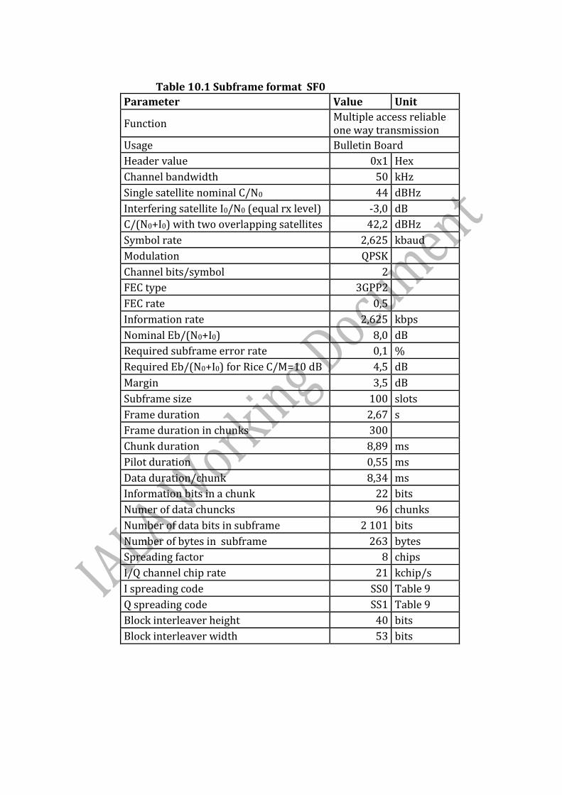
Table 10.1 Subframe format SF0
Parameter Value Unit
Function Multiple access reliable one way transmission
Usage Bulletin Board
Header value 0x1 Hex
Channel bandwidth 50 kHz
Single satellite nominal C/N0 44 dBHz
Interfering satellite I0/N0 (equal rx level) -3,0 dB
C/(N0+I0) with two overlapping satellites 42,2 dBHz
Symbol rate 2,625 kbaud
Modulation QPSK
Channel bits/symbol 2
FEC type 3GPP2
FEC rate 0,5
Information rate 2,625 kbps
Nominal Eb/(N0+I0) 8,0 dB
Required subframe error rate 0,1 %
Required Eb/(N0+I0) for Rice C/M=10 dB 4,5 dB
Margin 3,5 dB
Subframe size 100 slots
Frame duration 2,67 s
Frame duration in chunks 300
Chunk duration 8,89 ms
Pilot duration 0,55 ms
Data duration/chunk 8,34 ms
Information bits in a chunk 22 bits
Numer of data chuncks 96 chunks
Number of data bits in subframe 2 101 bits
Number of bytes in subframe 263 bytes
Spreading factor 8 chips
I/Q channel chip rate 21 kchip/s
I spreading code SS0 Table 9
Q spreading code SS1 Table 9
Block interleaver height 40 bits
Block interleaver width 53 bits
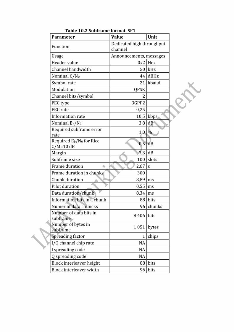
Table 10.2 Subframe format SF1
Parameter Value Unit
Function Dedicated high throughput channel
Usage Announcements, messages
Header value 0x2 Hex
Channel bandwidth 50 kHz
Nominal C/N0 44 dBHz
Symbol rate 21 kbaud
Modulation QPSK
Channel bits/symbol 2
FEC type 3GPP2
FEC rate 0,25
Information rate 10,5 kbps
Nominal Eb/N0 3,8 dB
Required subframe error rate
1,0 %
Required Eb/N0 for Rice C/M=10 dB
0,5 dB
Margin 3,3 dB
Subframe size 100 slots
Frame duration 2,67 s
Frame duration in chunks 300
Chunk duration 8,89 ms
Pilot duration 0,55 ms
Data duration/chunk 8,34 ms
Information bits in a chunk 88 bits
Numer of data chuncks 96 chunks
Number of data bits in subframe
8 406 bits
Number of bytes in subframe
1 051 bytes
Spreading factor 1 chips
I/Q channel chip rate NA
I spreading code NA
Q spreading code NA
Block interleaver height 88 bits
Block interleaver width 96 bits

4. Link layer 4.1 Data encapsulation A subframe consist of multiple variable length datagrams and these are encapsulated. Each datagram contain the following encapsulation fields:
- Datagram type (1 byte) - Datagram size (3 bytes) - Destination (4 bytes, optional) - Transaction ID (4 bytes, optional) - Datagram sequence number (2 bytes, for multisegment datagrams) - Source ID (8 bytes, optional) - Datagram payload (variable) - Data padding (variable, less than 8 bits) - CRC (4 bytes)
4.2 Cyclic Redundancy Check The 32 bit ITU polynomial 0x04C11DB7 CRC is appended to the last segment of the datagram. The CRC is calculated over all fragments of the datagram. F(x)=x32 + x26 + x23 + x22 + x16 + x12 + x11 + x10 + x8 + x7 + x5 + x4 + x2 + x + 1 Initial state: 0xFFFF 4.3 Automatic repeat request (ARQ) Datagrams may or may not use ARQ, this is defined for each datagram type. An ARQ will request selective retransmission of a specific lost datagram segment. 4.4. Acknowledgement (ACK) All datagrams without CRC errors are acknowledged over the satellite link. 4.5 End delivery notification (EDN) All datagrams successfully delivered to the destination will be notified to the source. 4.5 End delivery failure (EDF) All datagrams not successfully delivered within the timeout or retry limit will be notified to the source. 4.6 Physical and Logical channels VDES uses several channels to carry data. These channels are separated into Physical and Logical channels. Every satellite transmits a Bulletin Board that defines the configuration of these channels.
4.7 Physical Channels The Physical Channels (PC) are determined by the center frequency, subframe format and start timeslot. 4.8 Logical Channels (LC) The logical channels are divided into signalling and data channels. These are described below.

4.9 Signaling Logical Channels The following downlink signalling channels are used:
- Bulletin Board - Datagram announcements - Media Access Control (MAC) - Uplink and downlink resource allocation - Repeat requests/Acknowledgements/End delivery notifications
4.9.1 Bulletin Board Signalling Channel (BBSC) The Bulletin Board defines the network configuration parameters such as signalling channels (control channels) and data channel(s), protocol versions and future network configuration.
A logical channel is defined by function, index, center frequency , subframe format and startslot. The logical channels are normally repeated every frame, unless a network configuration change has taken place to optimises capacity. Satellite parameters and network ID are also provided. Information about other satellites and networks may be provided. The Bulletin Board information does not change often, and for a small LEO satellite it is sufficient that the Bulletin Board is received once per pass, a repeat rate of once per minute is sufficient for most passes. The BBSC uses subframe format SFF0 defined in Table 10.1 and shall be transmitted once every minute, starting at slot 0, the duration is 2.67 s. CDMA is used to allow multiple satellites with overlapping coverage to transmit the Bulletin Board at the same time. The ship receiver shall be able to receive Bulletin Boards from up to 8 satellites at the same time. The full bulletin board messages may be transmitted over several frames. Essential information of the bulletin board will be repeated over every frame (every 60 s).
4.9.2 Announcement Signalling Channel (ASC) This channel will normally carry Annoucements, MAC information, up/downlink resource allocation, ARQs, ACKs and EDNs. The channel is received by a large number of ships and a high margin subframe format is used. To reduce protocol latency the ASC may be repeated several times (different content) during a frame. Announcements include uni- and multi-cast (broadcast) datagrams. The ASC uses subframe format SFF0 or SFF1. The format the start slots are given defined in the Bulletin Board. The MAC information includes network version, congestion control (randomization interval, hold-off and minimum priority level). The uplink resource allocation provides uplink data channel information to an individual ship following a resource request.

4.9.3 Multicast Data Channel (MDC) This downlink channel is received by a large number of ships and a high margin subframe format is used. 4.9.4 Unicast Data Channel (UDC) This downlink channel is allocated a specific ship for the duration of a unicast datagram. This channel is set up after a ship responds to an announcement, and the response includes received signal quality information allowing the satellite to maximise throughput. 5. Network layer 5.1 Downlink data transfer protocols The following downlink protocols shall be supported:
- Bulletin Board transmission (network configuration) - Multicast (icemaps, weather info, notices to mariners) - Unicast (shore to ship file transfer, up to 100 kBytes)
The protocols are shown in Figures 12-14.
Figure 12. Bulletin Board with network version change

Figure 13. Multicast protocol (one-way)
Figure 14. Shore originated unicast (file transfer) protocol
6. Transport layer

6.1 End to end protocols Existing Internet protocols such as UDP, SNMP, Secure File Transfer Protocol (SFTP), Simple Mail Transfer Protocol (SMTP) as shown in Figures 12 to 14 are used. Terrestrial IP protocols are assumed to be terminated at the satellite gateway. 6.2 Ship, gateway and device physical addressing Most commercial ships use a 7 digit IMO number of which the last is a checksum, thus the IMO system can address 1 million ships. The 3 byte VDES physical addressing field has 16,7 million unique IDs. The number of networked devices on ships is growing fast and there is a need to directly address local gateways and devices. In addition to the 3 byte address field, a 1 byte subadressing has been added. The ship, local gateway and device addressing are shown in Table 11. Table 11. Ship, Gateway and Device addressing Adressing field Usage Range 24 bit physical address (all messages)
Ship terminal ID 16 Million
16 bit subaddress (encapsulated)
Ship gateway and device IDs
Configurable e.g. Gateway 4 MSB: 16 gateways Device 12 LSB: 4096 devices
6.3 Shore addressing of ships, gateways and devices VDES will be accessed from shore using Internet, and it is desirable to use standard protocols such as email. A database at the Gateway will allow shore users to define their own meaningful ship, gateway and device names. Below are some examples: 6.3.1 Setting engine exhaust gas temperature alarm level mail address: [email protected] Main body: id:whitestar pw:19101020 egtlimithigh: 250 6.3.2 Sending an icechart mail address: [email protected] Main body: id:whitestar pw:19101020

Attachment: nmiis201504101500.jpg
________________________________________________________________