Embed Size (px)
Citation preview

The Rehabilitation of Gaza Electricity Distribution and Transport Networks PAL-10-00063805
Annex 1Technical Specifications
Package1 - Lot 6
Supply Electrical & Steel Materials

Gaza�Electricity�Distribution�Corporation�LTD.�����������������������������������������������������������������������������������������������������������Edition:�March/2012�Technical�administration���Planning�Department����������������������������������������������������������������������������������
1��
Studies�and�Documentation�Section�����������������������������������������������������������Eng.�Wael�Ahmed�����������������������������������������������������������������������������������������������������������
��������������������������������������������������������
�
�
�
�
�
�
�
�
�
�
�
���� ����������� �� ���� ���������� �������
Gaza�Electricity�Distribution�Corporation��
TECHNICAL�SPECIFICATIONS�FOR�STEEL�STRUCTURES�
�
�
�
�
�
March�2012�

Gaza�Electricity�Distribution�Corporation�LTD.�����������������������������������������������������������������������������������������������������������Edition:�March/2012�Technical�administration���Planning�Department����������������������������������������������������������������������������������
2��
Studies�and�Documentation�Section�����������������������������������������������������������Eng.�Wael�Ahmed�����������������������������������������������������������������������������������������������������������
��������������������������������������������������������
1 GENERAL SPECIFICATIONS
1.1 Completeness of Contract
� 1.1.1� All�apparatus,�accessories�or�fittings�which�may�not�have�been�specifically�mentioned,�but�which�are�usual�or�necessary�in�the�respective�equipment�for�the�completeness�of�the� finished� work� in� an� operable� status,� shall� be� deemed� to� be� included� in� the�Contract� and� shall� be� provided� by� the� Contractor� without� any� extra� charge.� All�equipment�shall�be�complete�in�all�details,�whether�or�not�such�details�are�mentioned�in� the� Specifications.� This� includes� fixation� details� and� connection� clamps� and/or�terminals.�
1.1.2� Any�reference�in�the�quantity�and�price�schedules,�the�delivery�period�schedule�or�in�the�various�clauses�and�schedules�of�the�text�of�either�the�Specification�or�the�Bid,�to�any� equipment� shall� imply� that� the� equipment� is� complete� with� all� accessories,�apparatus�and�fittings�as�outlined�in�sub�clause�1.1.1�above.�
1.1.3� The�Bidder�shall�be�responsible�for�ensuring�that�the�equipment�supplied�is�fit�for�the�purpose� intended.� Available� information� on� the� characteristics� of� the� system� to�which�the�works�will�be�connected�and�associated�will�be�supplied�on�request�to�the�Bidder� who� shall� be� responsible� for� obtaining� and� determining� all� applicable�knowledge�relevant�to�the�works.�
1.2 Drawings and Documentation
The� Contractor� shall� prepare� and� submit� to� the� Engineer/GEDCO� for� approval� dimensioned�general� and� detailed� design� drawings� and� other� pertinent� information� of� all� the� Equipment�specified�in�the�Specifications.�
The�Contractor�shall�supply�detailed�instructions�for�erection,�operation�and�maintenance�of�all�equipment�and�components�in�English�and�preferably�Arabic�language.�
In� the� event� of� any� difference� between� the� drawings� and� the� Specifications,� the� latter� shall�prevail.�
Approval� of� drawings� shall� not� relieve� the�Contractor� of� his� obligations� to� supply� the�Plant� in�accordance�with� the�Specifications.� In� the�event�of� any�difference�between� scaled�dimensions�and�figures�on�the�drawings,�the�figures�shall�prevail�
All� text�on�drawings�provided�by�the�Contractor�shall�be� in� the�English� language� in�addition,� if�necessary,�to�that�of�the�country�of�origin.�
All�drawings�shall�be�dimensioned�in�millimeters.�
1.3 Time of Delivery and Completion
The�guaranteed�delivery�times�shall�be�stated�in�the�appropriate�schedule�in�this�document.�

Gaza�Electricity�Distribution�Corporation�LTD.�����������������������������������������������������������������������������������������������������������Edition:�March/2012�Technical�administration���Planning�Department����������������������������������������������������������������������������������
3��
Studies�and�Documentation�Section�����������������������������������������������������������Eng.�Wael�Ahmed�����������������������������������������������������������������������������������������������������������
��������������������������������������������������������
1.4 Quality of Materials
All�materials�supplied�under�this�Contract�shall�be�new�and�of�the�best�quality�and�of�the�class�most� suitable� for�working�under� the� conditions� specified�and� shall�withstand� the�variations�of�temperature�and�atmospheric�conditions�arising�under�working�conditions�without�distortion�or�deterioration� in� the� setting� up� of� undue� stresses� in� any� parts� and� also� without� affecting� the�suitability� of� the� various� parts� of� the�Works� for�which� they�were� designed.� No� toxic�material�(such�as�Halon,�PCB,�and�Asbestos)�shall�be�utilized.�
1.5 Contractor's Quality Assurance Procedures
The�Bidder� shall�have�established�a�quality� assurance�system�based�on� ISO�9001�or�9002.�The�Contractor� shall� include� a� documentation� of� the� system�with� a� list� of� current� procedures,� an�organogram� of� the� quality� organization� and� the� name� of� the� quality� manager.� He� shall� also�submit� a� list� of� quality� revisions� performed� the� last� twelve� months� with� a� list� of� closed� and�unclosed�findings�as�well�planned�revisions�the�coming�twelve�months.�
The�Contractor�shall�submit�for�approval�a�program�of�quality�control�and�inspection�procedures�to�assure�that�the�product�during�manufacture�and�on�completion�complies�with�the�specified�requirements.� The� program� shall� relate� the� quality� control� and� inspection� activities� to� the�production�cycle.� In�support�of�the�quality�control�and�inspection�program�the�Contractor�shall�provide�details�of�quality�control�and�inspection�procedures�available�for�use�in�the�execution�of�the� Contract.� The� Contractor� shall� retain� responsibility� for� quality� control� and� inspection�activities�made�by�his�sub�contractors�and�shall�indicate�on�the�program,�which�items�are�to�be�sub�contracted.�
1.6 Guarantees and Particulars
The�Works�shall�comply�with�the�technical�guarantee�data�stated�in�the�Bid.�The�Contractor�shall�be� responsible� for� any� discrepancies,� errors� and� omissions� in� the� particulars� and� guarantees,�whether�the�Engineer/GEDCO�has�approved�such�particulars�and�guarantees�or�not.�
1.7 Places of Manufacture and Sub-Contractors
The�manufacturer's�identity�and�places�of�manufacture,�testing�and�inspection�before�shipment�for�the�various�portions�of�the�Contract�Works�shall�be�specified�in�the�Technical�Schedules�and�shall�not�be�departed�from�without�the�agreement�of�the�Engineer/GEDCO.�
�
�
All� Sub�contractors� and� Sub�suppliers� of� components� and� materials� shall� be� subject� to� the�approval� of� the� Engineer/GEDCO.� Information� shall� be� given� on� each� Sub�order� sufficient� to�identify� the�material�or�equipment,� to�which�the�sub�order�relates,�stating�that�the�material� is�subject�to�inspection�by�the�Engineer/GEDCO�before�dispatch.�

Gaza�Electricity�Distribution�Corporation�LTD.�����������������������������������������������������������������������������������������������������������Edition:�March/2012�Technical�administration���Planning�Department����������������������������������������������������������������������������������
4��
Studies�and�Documentation�Section�����������������������������������������������������������Eng.�Wael�Ahmed�����������������������������������������������������������������������������������������������������������
��������������������������������������������������������
All� equipment�offered� shall� be� the�product�of� recognized� and�experienced�manufacturers� and�shall�be�proven�equipment�of�the�same�basic�design�and�size�similar�to�that�which�has�been�in�successful� continuous� operation� for� at� least� three� years� preferably� under� similar� climatic�conditions.� Proven� plant� reliability� and� high� availability� are� of� prime� importance� and� the�attention�of�the�Bidder�is�drawn�to�these�particular�requirements.�
1.8 Inspection and Testing
All�materials�used�in�the�Contract�Works�may�be�to�inspection�by�the�Engineer/GEDCO�and�it�is�the�Contractor's�responsibility�to�advise�the�Engineer/GEDCO�when�equipment�and�materials�are�available�for�inspection,�at�least�1�month�in�advance.�
Factory� tests� on� equipment� shall� be� made� according� to� the� applicable� IEC� Standards,� or� as�specifically�specified�or�according�to�standards�approved�by�the�Engineer/GEDCO.�
Routine�tests�shall�be�made�on�each�unit�of�all�equipment.�
Type�tests�shall�be�made�on�one�unit�of�each�type�of�different�equipment.�Instead�of�carrying�out�the�type�tests�the�Contractor�may�submit�suitable�certificates�of�tests�made�on�equipment�of�the�same�type;�however,�the�Employer�reserves�the�right�of�accepting�these�certificates�or�to�reject�them�partially�or�totally.�
The�Engineer/GEDCO�shall�be�at�liberty�to�demand�any�additional�testing�at�the�manufacturer's�works,�at�site�or�elsewhere�in�order�to�verify�that�the�equipment�complies�with�the�conditions�of�the�Specifications.�
A�test�program�shall�be�submitted�to�the�Engineer/GEDCO�for�approval�at�least�1�month�ahead�of�the�commencement�of�testing.�
Measuring� apparatus� shall� be� approved� by� the� Engineer/GEDCO� and� if� required� shall� be�calibrated�at�the�expense�of�the�Contractor�at�an�approved�laboratory.��
1.9 Packing, Transportation and Storage
Packing� shall� give� adequate� protection� to� the� enclosed�materials� against�mechanical� damage�during� transport� to� its� final� destination,� including� rough� handling� during� sea,� rail� and� road�transport�and�transition�from�one�mode�of�transport�to�another.�
Packing�should�be�stout�close�boarded�wooden�cases�of�adequate�thickness,�suitably�braced�and�banded�and�lined�internally�with�water�resistant�material�or�equally�solid�enclosures.�
�
Steelworks� sections� and� similar� items�may�be�bundled�provided� that� the� ends� are� adequately�protected�and�the�enclosing�bands�or�wires�are�robust.�
Indoor� electrical� equipment� must� be� enclosed� in� welded� polythene� envelopes� inside� packing�cases�and�the�envelopes�shall�be�evacuated�or�have�a�desiccant�inside.�

Gaza�Electricity�Distribution�Corporation�LTD.�����������������������������������������������������������������������������������������������������������Edition:�March/2012�Technical�administration���Planning�Department����������������������������������������������������������������������������������
5��
Studies�and�Documentation�Section�����������������������������������������������������������Eng.�Wael�Ahmed�����������������������������������������������������������������������������������������������������������
��������������������������������������������������������
All�items�in�cases�or�crates�shall�be�secured�so�that�they�are�not�free�to�move�and�cannot�work�loose�in�transport.�If�rotating�parts�are�shipped�within�their�bearings�or�mountings,�they�must�be�adequately�braced�and�restrained�to�prevent�relative�movement.�Loose�items�shall�be�placed�in�bags�in�a�case,�each�bag�having�stitched�onto�it�a�label� indicating�the�number�and�nature�of�its�contents.�Where� a� filler�material� is� used� in� a� case� to� restrict�movement�or� provide� additional�protection,�it�must�be�inorganic�and�non�hygroscopic.�
All� surfaces� liable� to� corrosion� shall� be� thoroughly� cleaned� and� special� steps� adapted� to� the�nature�of�the�materials�and�the�time�interval�between�packing�and�unpacking�shall�be�taken�to�prevent� corrosion.� These� steps�may� constitute� the� greasing� on� surfaces,� the� application� of� a�protective�coat,�enclosure�of�the�items�in�a�hermetically�sealed�container,�the�addition�of�vapour�phase�inhibitor�paper�to�the�package�or�other�approved�means.�
Steps� shall� be� taken� to� ensure� that� moisture,� moulds,� insects� or� rodents� cannot� damage�insulated� materials.� Items� that� include� materials� liable� to� be� damaged� by� moisture� shall� be�packed� in�hermetically�sealed�containers� in�which�silica�gel,�or�some�other�approved�desiccant�has�been�inserted.�
Cases�shall�be�marked�with�large�lettering�to�show�which�side�of�the�case�is�to�be�up,�and�if�the�contents�are�fragile,�marked�“FRAGILE”�in�large�letters�with�the�international�wineglass�symbol.�Packages�shall�be�marked�with�their�place�of�destination�in�such�a�way�that�rough�handling�or�the�effect�of�weather�cannot�remove�or�obliterate�the�marking.�Each� item�shall�be�marked�with�its�gross� weight� and,� for� all� lifts� over� two� tonnes,� marks� on� the� cases� shall� show� the� correct�positions�for�the�slings.�
Special� steps� shall� be� taken� to� guard� against� theft� during� transport.� No� small� items� such� as�padlocks�nameplates�and�so�forth�that�could�be�torn�off�or�unscrewed�shall�be�accessible.�
Cases,�crates,�barrels�and�drums�shall�be�banded�in�such�a�manner�as�to�obstruct�the�theft�of�any�of�the�timber�used�for�packaging�and�the�bands�shall�be�so�secured�that�they�are�not�rendered�ineffective�by�shrinkage�of�the�wood.�
A�descriptive� and� fully� itemized� list� shall� be�prepared�of� the� contents�of� each�packing� case.�A�copy�of�this� list�shall�be�placed�in�a�waterproof�envelope�under�a�metal�or�other�suitable�plate�securely�fastened�to�the�outside�of�one�end�of�the�case,�and�its�position�indicated�by�stenciling�on� the� case.� Where� appropriate,� drawings� showing� the� erection� markings� of� the� items�concerned�shall�be�placed�inside�the�case.�
All�stenciled�markings�on�cases�and�crates,�or�other�markings�on�descriptive�metal�tabs�fixed�to�cable�drums,�bundles�of�structural�steel�works�and�so�forth,�shall�be�applied�in�two�places�with�a�material� which� cannot� wash� off� and� shall� be� additional� to� any� erection� or� other� marks� or�impressions�which�may�be�specified�elsewhere.�
�
Shipping� marks� are� to� be� stenciled� in� oil� based� paint� in� block� letters� and� symbols.� When�unobstructed�flat�smooth�surfaces�of�sufficient�size�are�not�available�on�the�case�for�the�shipping�marks�they�are�to�be�stenciled�on�marine�ply�notice�boards�of�adequate�size�and�of�at�least�6�mm�thickness�securely�fastened�to�the�packing�case.�

Gaza�Electricity�Distribution�Corporation�LTD.�����������������������������������������������������������������������������������������������������������Edition:�March/2012�Technical�administration���Planning�Department����������������������������������������������������������������������������������
6��
Studies�and�Documentation�Section�����������������������������������������������������������Eng.�Wael�Ahmed�����������������������������������������������������������������������������������������������������������
��������������������������������������������������������
All�packing�cases,�though�not�steel�containers,�shall�remain�the�property�of�the�Employer.
1.10 Tools
The�Supplier�shall�supply�in�lockable�boxes,�for�the�Employer’s�use,�any�special�tools�that�may�be�required�for�assembly,�dismantling�and�adjustments�to�the�equipment.�The�tools�shall�be�unused�and� in�new�condition�at�the�time�of�hand�over.�Suitable�special�spanners�shall�be�provided�for�bolts�and�nuts�which�are�not�properly�accessible�by�means�of�an�ordinary�spanner.�
1.11 Spare Parts
Particulars�of�spare�parts,�which�may�or�not�from�part�of�the�contract�at�the�Purchaser's�discretion,�shall�be�agreed.�Bidders�giving�their�recommendations�should�complete�the�relevant�Schedules�and�prices�for�spares�that�they�believe�should�be�purchased�by�Purchaser���
�
�
�
�
�
�
�
�
�
�
�
�
�
�
�
�
�
�

Gaza�Electricity�Distribution�Corporation�LTD.�����������������������������������������������������������������������������������������������������������Edition:�March/2012�Technical�administration���Planning�Department����������������������������������������������������������������������������������
7��
Studies�and�Documentation�Section�����������������������������������������������������������Eng.�Wael�Ahmed�����������������������������������������������������������������������������������������������������������
��������������������������������������������������������
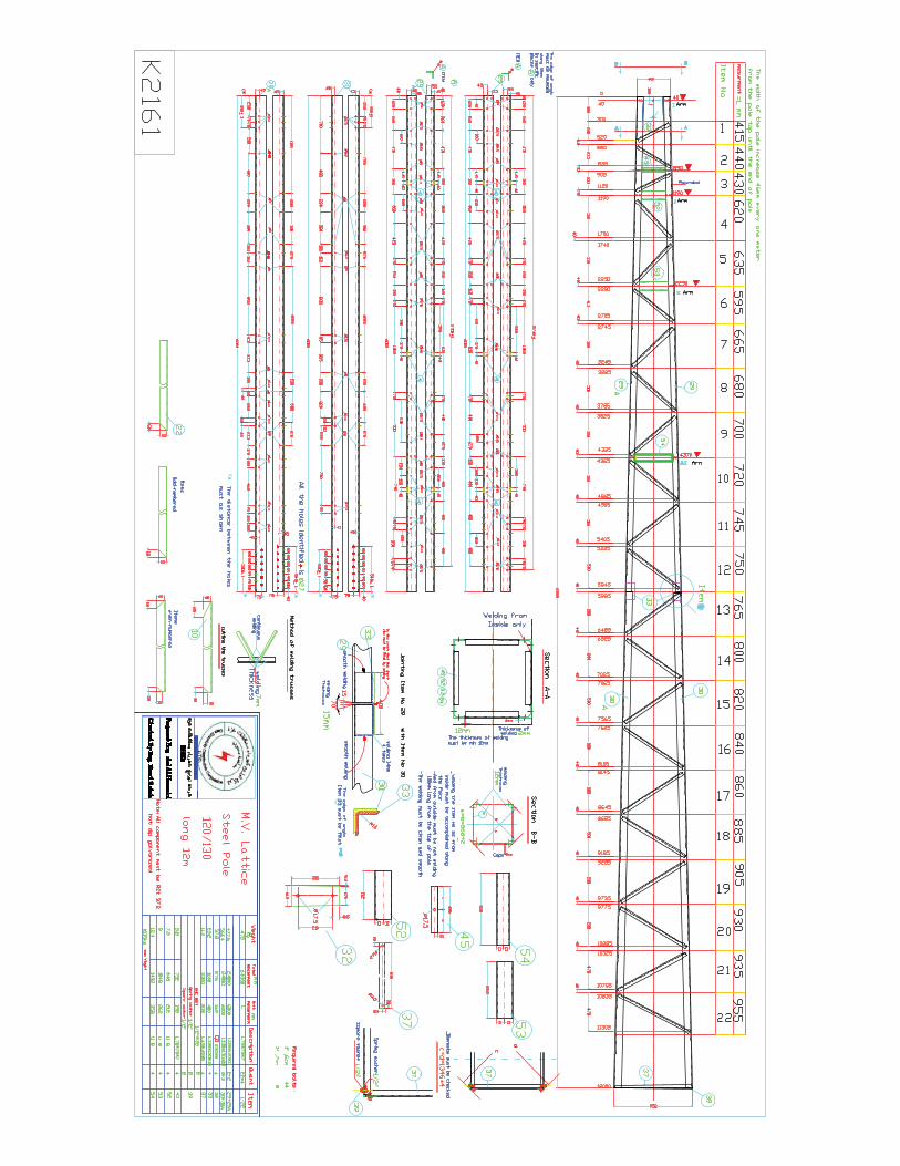
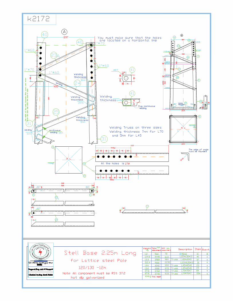
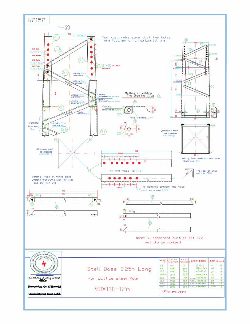
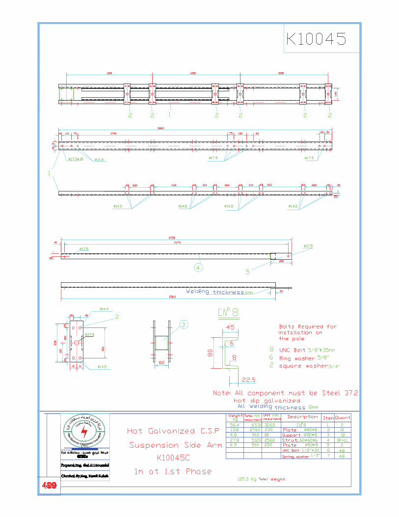
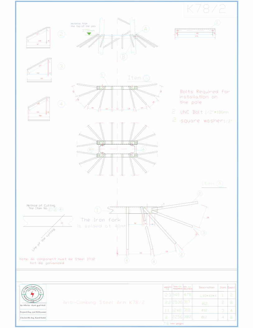
2.����PARTICULAR�TECHNICAL�SPECIFICATIONS�FOR�STEEL�STRUCTURE�������������
General�
� Steel�structures�shall�be�of�lattice�steel�self�supporting,�bolted�construction.�
� The� structures� shall� be� designed� with� main� dimensions� and� electrical� clearances� according� to� the�Employer’s�standard�design.�
� The� structures� shall� be� designed� in� accordance� with� BS,� ASCE� or� other� recognized� standard� to� the�approval�of�the�Engineer.�
��������
2.1�Structure�types���
�������������The�types�and�sizes�of�structure�shall�be�as�described�in�the�schedule�of�quantities�and�prices.�The�types�and�design�shall�comply�with�GEDCo�and�Israeli�standard�practice.�
�������
2.2�Accessories�to�structures��
��������������All�accessories,�such�as�cross�arms,�transformer�arms,�brackets,�bases,�bolts,�nuts,�washers�and�all�other�parts� necessary� for� completeness� of� supply� shall� be� included� in� the� supply� and� be� suitable� to� the�structures�as�described�in�the�schedule�of�quantities�and�prices.�All�accessories�shall�be�compliance�with�GEDCo�and�Israeli�standard�practice�
������
2.3��Corrosion�Protection�
2.3.1�General�
� �All�parts�of�the�work�shall�be�protected�against�corrosion�under�service�conditions.�The�protection�shall�also�prevent�corrosion�during�transport,�handling,�storage�and�erection.�
� �Damage�to�the�protection�during�transport,�handling,�erection�etc.�and�jointing�shall�be�repaired�to�the�same�quality�as�specified�for�the�object.�
� �
2.3.2�Galvanizing� �
� �Except�where�otherwise�specified�all�ferrous�parts�shall�be�galvanized.�
� �Galvanizing� shall� be� applied� by� the� hot�dip� process� and� shall� consist� of� a� continuous� coating� to�minimum�thickness�as�follows:�
�

Gaza�Electricity�Distribution�Corporation�LTD.�����������������������������������������������������������������������������������������������������������Edition:�March/2012�Technical�administration���Planning�Department����������������������������������������������������������������������������������
8��
Studies�and�Documentation�Section�����������������������������������������������������������Eng.�Wael�Ahmed�����������������������������������������������������������������������������������������������������������
��������������������������������������������������������
� �� � � � ��Average�of� � ��Any�Individual�� �� � � � ��Specimens�tested� ��Specimen�tested�� �� � � � ���m�(g/m2)� � ����m�(g/m2)��� �Rolled�steel�exposed�to�� the�atmosphere�only� t<5�mm���87�(��610)� �������������79�(�550)�� �� � ������������t>5�mm� ���95�(685)� �������������87�(610)��� �Rolled�steel�under�ground�� �Surface�and�in�contact�with��� ��215�(1550)� � 190�(1370)�� ground�� ��������������Cast�iron�and�malleable�iron����������� 87�(610)� � �70�(500)��� �� Bolts,�nuts�and�washers� ���������������45�(305)� � �45�(305)��
� �The� zinc� coating� shall� meet� the� requirements� according� to� ASTM� A123,� A153,� A239� and� A385,� or�relevant�BS.�
� �All�steel�shall�be�fully�fabricated�before�galvanizing,�no�machine�or�shop�work,�boring,�punching�etc.�will�be�allowed�after�galvanizing.� �Minor�damage�to�the�galvanizing�resulting� from�transportation�and�the�like�shall�be�repaired�at�site�in�an�approved�manner,�e.g.�by�painting�with�an�approved�zinc�rich�paint,�containing�at�least�92�weight�per�cent�zinc�powder.�
� �After�galvanizing�all�members�shall�be�dipped�in�a�dichromate�solution�bath�to�avoid�formation�of�white�rust�during�storage�and�transportation.�
� �Prior�to�bundling�of�towers,�after�galvanizing,�all�members�shall�be�completely�dry.�
� �Underground�parts�shall�be�coated�with�one�layer�of�bitumen�after�installation�on�site.�
�����2.4�� Structural�Steel��
� Structural�steel�shall�be�made�by�the�open�hearth�basic�oxygen�or�electrical�furnace�process,�and�shall�comply� in�quality�with� the� requirements� for�RST37�2� in�DIN17100�or�Grade�43�A� in�BS�4360�Steel�of�higher�tensile�grade�if�offered,�shall�comply�with�relevant�DIN�or�BS�Standards.�
� Only�two�strength�classes�may�be�used,�low�tensile�steel�(yield�point�220�250�N/mm2)�and�a�high�tensile�steel�(yield�point�300�350�N/mm2).�
� Steel� shall� comply� with� the� requirements� of� ASTM� A143� and� embitterment� tests� shall� be� made� in�accordance�with�that�specification.�
� If� the� Contractor� intends� to� use� more� than� one� quality� of� steel,� he� will� be� required� to� take� every�precaution� to� the� satisfaction� of� the� Employer� or� the� Engineer� against� any� possible� intermixing� of�different�qualities�during�transport,�storage,�handling,�manufacture�and�installation.�
� Cast�iron�shall�have�a�tensile�strength�of�at�least�140�N/mm2.�It�shall�be�made�from�the�best�grey�pig�and�scrap�iron�and�shall�be�close�grained,�tough�and�uniform�in�character.�
� Malleable�iron�shall�be�of�the�black�hearth�type�with�a�tensile�strength�of�not�less�than�330�N/mm2.�
�

Gaza�Electricity�Distribution�Corporation�LTD.�����������������������������������������������������������������������������������������������������������Edition:�March/2012�Technical�administration���Planning�Department����������������������������������������������������������������������������������
9��
Studies�and�Documentation�Section�����������������������������������������������������������Eng.�Wael�Ahmed�����������������������������������������������������������������������������������������������������������
��������������������������������������������������������
2.5����Bolted�Connections�
����������Bolts�shall�conform�to�the�requirements�of�clause�1.6�below��
� Bolted�connections�may�have�one�bolt�only.�
� Minimum�bolt�spacing�is�equal�to�two�point�five�(2.5)�times�the�bolt�diameter.�
� The�distance� from�the�Centre�of�a� fastener�hole� to� the�end�and�any�connected�part� shall�not�be� less�than�two�(2.0)�times�the�bolt�diameter�minus�five�(5.0)�mm�and�the�distance�to�the�adjacent�edge�shall�not�be�less�than�one�point�five�(1.5)�times�the�bolt�diameter.�
� The� distance� from� the� Centre� of� a� bolt� to� the� face� of� the� outstanding� flange� of� an� angle� or� other�members�shall�be�such�as�to�permit�the�use�of�a�socket�wrench,�in�tightening�the�nut.�
� The�bolt�hole�diameter�shall�be�equal�to�the�bolt�diameter�plus�one�point�five�(1.5)�mm.�
� Allowable�ultimate�bearing�stress�for�bolts�as�well�as�members�are�equal�to�one�point�zero�(1.0)�times�the�ultimate�stress�Fu�of�the�steel.�
� Allowable� ultimate� shearing� stress� for� bolts� and�members� is� equal� to� zero� point� six� (0.6)� times� the�ultimate�stress�Fu�of�the�steel.�
����2.6���Bolts,�Nuts�and�Washers�
� Bolts�in�poles�shall�be�high�strength�with�M�threads.�Connection�bolts,�step�bolts�and�nuts�shall�be�high�strength�bolts�conforming�to�ASTM���A325�or�equivalent,�except�as�specified�herein�and shall be hot dip galvanized.�
� Bolts�and�nuts�shall�be�of�standard�design.�Nuts�shall�be�tapped�after�galvanizing�and�the�threads�of�the�nuts� left� bare� and� greased.�Washers� shall� be� used� under� the� nuts.� Bolt� lengths� shall� be� such� as� to�ensure�that�bearing�is�upon�the�shank�and�not�upon�the�thread�of�the�bolt.�The�threaded�part�shall�end�within�the�washer.�When� installed,� the�bolt�shall�project� through� the�nut�not� less� than�three� (3)�mm�and�not�more�than�ten�(10)�mm.�Taper�washers�shall�be�used�where�required.�
��������������An�extra�5%�bolts,�nuts�and�washers�shall�be�delivered�to�compensate�for�loss�during�construction.�The�cost�of�the�extras�shall�be�included�in�the�appropriate�unit�prices�in�the�Prices�Schedules.�
�����2.7� ���Splices�
� Splices�in�all�members�shall�be�of�the�butt�splice�or�lap�splice�type.�
Splices�of�the�main�members�shall�be�located�immediately�above�horizontal�members�or�diagonal�brace�connection.�
�
����2.8� ����Cutting�
� Members�shall�be�cut,�drilled�or�punched�and�shaped�to� jig�or�by�other�means�ensuring�a�proper� fit.�Arris�formed�by�sawing�or�shearing�shall�be�removed.�Cracks�and�unevenness�or�sheared�surface�shall�be�removed�by�suitable�means.�Burrs�shall�be�removed.�
�
�����2.9� ����Holes�
� Final�hole�diameter�may�not�exceed�the�corresponding�bolt�diameter�by�more�than�1.5�mm.�Holes�may�be�punched�to�full�size�in�steel�not�exceeding�13�mm�in�thickness�provided�that�the�diameter�of�the�hole�

Gaza�Electricity�Distribution�Corporation�LTD.�����������������������������������������������������������������������������������������������������������Edition:�March/2012�Technical�administration���Planning�Department����������������������������������������������������������������������������������
10��
Studies�and�Documentation�Section�����������������������������������������������������������Eng.�Wael�Ahmed�����������������������������������������������������������������������������������������������������������
��������������������������������������������������������
exceeds�the�thickness�of�the�material.�Holes�in�steel�thicker�than�13�mm�may�be�punched�to�a�diameter�3�mm�less�than�final�and�Centre�drilled�to�full�size.�Steel�thicker�than�16�mm�must�not�be�punched.�
� Incorrectly�drilled�or�punched�holes�shall�not�be�refilled�by�welding.�
� Cutting�and�punching�may�not�be�carried�out�at�lower�steel�temperature�than�0OC.�
� Detail�design�shall�be�such�as�to�avoid�as�far�as�possible�eccentricities�of�joints.�Pockets�or�depressions�which�would�hold�water�shall�be�avoided.�Tubes�and�similar�profiles�shall�be�properly�drained.�
2.10�����������Labeling:�
�����������������All�materials�shall�have�Fixed�steel�or�Aluminium�Non�erasable�Clearly�readable�large�enough�Label�to�Reading�including�Name,�Code�of�the�Poles�,Bases�,Arms�and�If�the�Arms�supply�more�than�One�piece�the�Manufacturer�shall�Fix�the�Labels��on�every�Part�of�the�Arms.�
���������������The�Label�shall�fix�on�3�meter�from�the�Ground�in�the�Outer�Interface�for�Poles.�
���������������The�Label�shall�fix�on�the�top�of�the�Bases�in�the�Outer�Interface.�
���������������The�Label�shall�fix�In�the�outer�edge�of�the�bottom�of�the�Arms�Away�from�the�Poles�.�
�
2.11� ����Welding�
������������2.11.1��Qualifications�for�Executing�the�Welding�Work�
�������������The� welding� work� on� the� structures,� if� employed,� shall� be� performed� with� a� labour� management�experienced�in�welding�and�with�skilled�welders.��The�qualifications�shall�be�testified�by�a�certificate.�
�����������2.11.2��Execution�of�the�Welding�Work�
� The�sequence�of�welding�shall�be�such�as�to�cause�as�small�deformations�and���welding�stresses�as�possible.�
� The�welding�shall�be�performed�with�equipment�and�in�premises�suitable�for�the�purpose.�
� Equipment�shall�be�well�suited�to�the�type�of�weld�to�be�performed�so�that�the�right�quality�shall�be�attained.�
� � No�gaps�or�hollows�may�appear�in�the�welding�into�which�acid�may�penetrate�during�the�pickling�procedure�preceding�galvanizing.�
�� The�weld�shall�be�ground�flush�to�the�surface�in�such�places�where�the�welding�bulge�prevents�a�perfect�fitting�of�components�together.�
�� A�high�bulge�or�uneven�weld�surface�may�be�leveled�out�by�chiseling�or�grinding.�
�
����������2.11.3��Filler�Metals�for�Welding�
�� Standard� filler� metals� shall� be� used� and� the� strength� class� and� quality� shall� be� chosen� to�correspond�to�the�base�material.�
2.12���������������Acceptance�
GEDCO�has�the�right�to�visit�the�factory�before�manufacturing�also�has�the�right�to�request�samples�and�examined�by�the�committee�in�charge�also�has�the�right�to�refuse�the�all�non�conforming�materials.��


Gaza Electricity Distribution Corporation LTD.
No Description Unit Requirements Offered DataNotes, Remarks
, Ref to Documentation
Evaluation Committee Comments
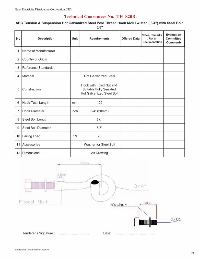
1 Name of Manufacturer
2 Country of Origin
3 Reference Standards
4 Material Hot Galvanized Steel
5 ConstructionHook with Fixed Nut and Suitable Fully Serrated
Hot Galvanized Steel Bolt
6 Hook Total Length mm 120
7 Hook Diameter inch 3/4" (20mm)
8 Steel Bolt Length 3 cm
9 Steel Bolt Diameter 5/8"
10 Failing Load KN 20
11 Accessories Washer for Steel Bolt
12 Dimensions As Drawing
Technical Guarantees No. TH_S20BABC Tension & Suspension Hot Galvanized Steel Pole Thread Hook M20 Twisted ( 3/4") with Steel Bolt
5/8"
Tenderer’s Signature : ……………………..… Date: ………………………………
Studies and Documentation Section1/1


Gaza Electricity Distribution Corporation LTD.
No Description Unit Requirements Offered DataNotes, Remarks
, Ref to Documentation
Evaluation Committee Comments
1 Name of Manufacturer
2 Country of Origin
3 Description Cable Guard
4 Material Hot Dip Galvanized
5 Steel Guard with Steel Cover Required
6 Steel Guard and Steel Cover Length mm 2000
7 Steel Guard Width mm 160
8 Steel Cover Width mm 165
9 Steel Guard Edge Height mm 150
10 Cover Edge Height mm 26
11 Steel Guard and Steel Cover Thickness mm 1.5
12 Holes 15x5 mm Required
13 Attached Drawing Drawing No. SCG_200A
Technical Guarantees No. SCG_200AHot Galvanized Steel Cable Guard
Tenderer’s Signature : ……………………..… Date: ………………………………
Studies and Documentation Branch1/1

Gaza Electricity Distribution Corporation LTD.
No Description Unit Requirements Offered Data
Notes, Remarks , Ref
toDocumentation
Evaluation Committee Comments
1 Name of Manufacturer
2 Country of Origin
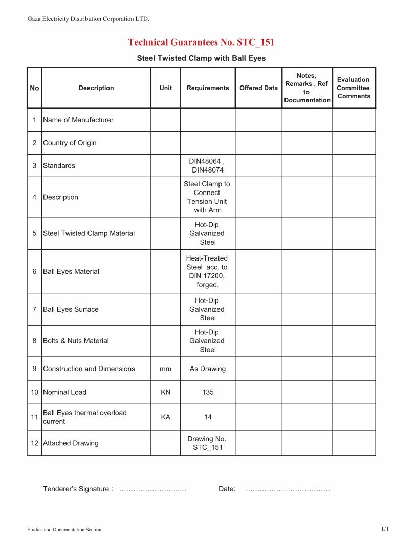
3 Standards DIN48064 , DIN48074
4 Description
Steel Clamp to Connect
Tension Unit with Arm
5 Steel Twisted Clamp MaterialHot-Dip
Galvanized Steel
6 Ball Eyes Material
Heat-Treated Steel acc. to DIN 17200,
forged.
7 Ball Eyes SurfaceHot-Dip
Galvanized Steel
8 Bolts & Nuts MaterialHot-Dip
Galvanized Steel
9 Construction and Dimensions mm As Drawing
10 Nominal Load KN 135
11 Ball Eyes thermal overload current KA 14
12 Attached Drawing Drawing No. STC_151
Technical Guarantees No. STC_151Steel Twisted Clamp with Ball Eyes
Tenderer’s Signature : ……………………..… Date: ………………………………
Studies and Documentation Section 1/1

�

Gaza Electricity Distribution Corporation LTD.
No Description Unit Requirements Offered DataNotes, Remarks
, Ref to Documentation
Evaluation Committee Comments
1 Name of Manufacturer
2 Country of Origin
3 Connecting Dimensions Standards DIN 48064
4 Material Standards DIN 1692
5 Surface Standards DIN 50976
6 Material Malleable cast iron GTS-45
7 Surface Hot-dip Galvanized
8 Upper Slot Dimension (A) mm 16
9 Nominal Load KN 160
10 Ball Eyes thermal overload current KA 14
11 Construction and Dimensions mm As Below Drawing
Technical Guarantees No. FBH_16Fork Ball Hook 16mm (SOCKET EYES-TYPE-A)
Tenderer’s Signature : ……………………..… Date: ………………………………
Studies and Documentation Section1/1

Gaza Electricity Distribution Corporation LTD.
No Description Unit Requirements Offered Data
Notes, Remarks , Ref
toDocumentation
Evaluation CommitteeComments
1 Name of Manufacturer
2 Country of Origin
3 Connecting Dimensions Standards DIN 48064
4 Material Standards DIN 1692
5 Surface Standards DIN 50976
6 Material Malleable cast iron GTS-45
7 Surface Hot-dip Galvanized
8 Nominal Load KN 110
Technical Guarantees No. HMC_01
Strain Thimbles with Socket (Half Moon Clamp)
Studies and Documentation Section1/2

Gaza Electricity Distribution Corporation LTD.
No Description Unit Requirements Offered Data
Notes, Remarks , Ref
toDocumentation
Evaluation CommitteeComments
Technical Guarantees No. HMC_01
Strain Thimbles with Socket (Half Moon Clamp)
9 thermal overload current KA 14
10 Construction and Dimensions mm As Below Drawing
Tenderer’s Signature : ……………………..… Date: ………………………………
Studies and Documentation Section2/2

Gaza�Electricity�Distribution�Corporation�LTD.�����������������������������������������������������������������������������������������������������������Edition:�March/2012�Technical�administration���Planning�Department����������������������������������������������������������������������������������
1��
Studies�and�Documentation�Section�����������������������������������������������������������Eng.�Wael�Ahmed����������������������������������������������������������������������������������������������������������������������
���������������������������������������������
�
�
�
�
�
�
�
�
�
�
�
���� ����������� �� ���� ���������� �������
Gaza�Electricity�Distribution�Corporation��
Technical�Specifications�
For Hard�and�Soft�Drawn�Stranded�Copper�
Conductors�
�
March�2012�
�

Gaza�Electricity�Distribution�Corporation�LTD.�����������������������������������������������������������������������������������������������������������Edition:�March/2012�Technical�administration���Planning�Department����������������������������������������������������������������������������������
2��
Studies�and�Documentation�Section�����������������������������������������������������������Eng.�Wael�Ahmed����������������������������������������������������������������������������������������������������������������������
���������������������������������������������
1.� Hard�and�Soft�Drawn�Stranded�Copper�Conductors�
Scope�This�Specification�covers�the�design,�manufacture,�factory�test,�supply�and�delivery�of�Hard�and�Soft�Drawn� Stranded�Copper�Conductors� for� use� in� the� construction�of� 22kv,� 3�phase,� 4�wire,�overhead�distribution�systems�and�Frequency�50Hz.�
1.1� Description�
� The�conductor�shall�be�suitable�for�use�within�Gaza�Strip:�altitude�range�above�sea�level��50���+200�meters,�typical�temperature�range��5�oC�to�55�oC,�relative�humidity�70�95%.�
� All�conductors�should�be�of�copper�construction�and�shall�be�manufactured�in�strict�conformity�to�BS �7884 � for� hard� drawn� conductors� and� BSEN60228� for� Soft� drawn� conductors� with� general�specification�BSEN60228.�The�outermost�layer�of�all�conductors�shall�be�stranded�with�right�hand�lay.�
� The�correct�tension�must�be�maintained�on�the�stranding�machine�when�spinning�the�conductor�to� avoid� the� possibility� of� bird� caging� during� stringing.� Any� condition� not� complying� may� be�rejected�at�the�discretion�of�the�Engineer.�
� The�purity�of�the�Copper�shall�be�the�highest�commercially�available.�The�contractor�shall�submit�the� certificates� of� analysis� giving� the�percentage� and� the�nature�of� any� impurities� in� the�metal�from�which�the�wires�are�made.�
� The� conductors� manufacturing� company� shall� have� been� accredited� with� ISO� 9001� (including�design�in�the�scope�of�registration)�quality�certification.�
� The� other� technical� specifications� of� the� conductors� are� given� in� Technical� Guarantees� which�should�be�filled�and�stamped�by�manufacturer�and�Tenderer.�
�
1.2� Standards�
� Hard� Drawn� Conductor:� The� conductor� shall� comply� with� the� latest� revision� of� British� Sizes�BS7884�&�DIN�48201�
� Soft�Drawn�Conductor:�The�conductor�shall�comply�with�the�latest�revision�of�BSEN60228�
� Hard�Drawn�Solid�Conductor:�The�conductor�shall�comply�with�the�latest�revision�of�British�Sizes�BS13601�
�

Gaza�Electricity�Distribution�Corporation�LTD.�����������������������������������������������������������������������������������������������������������Edition:�March/2012�Technical�administration���Planning�Department����������������������������������������������������������������������������������
3��
Studies�and�Documentation�Section�����������������������������������������������������������Eng.�Wael�Ahmed����������������������������������������������������������������������������������������������������������������������
���������������������������������������������
1.3� Testing�
1.3.1� The�following�acceptance�and�routine�tests�shall�be�made�on�the�conductor�at�the�manufacturer's�plant�in�accordance�with�governing�standards�and�the�presence�of�the�witness�Committee,�which�includes�GEDCo�and/or�other�parties:�
a)�Tensile�test�
b)�Wrapping�test�
c)�Resistivity�test�
d)�Physical�tests�
All� the� acceptance� and� routine� tests� shall� be� conducted� as� per� the� relevant� standards� in� the�presence�of�purchaser's�representative.�The�values�shall�conform�to�guaranteed�values.�
Immediately� after� finalization� of� the� program�of� acceptance/routine� testing� the�manufacturer�shall� give� 15� days� advance� intimation� to� the� purchaser,� to� enable� him� to� depute� his�representative�for�witnessing�the�tests.�
1.3.2� The�manufactured�conductor�shall�be�tested�in�full�compliance�with�the�governing�standard�and�a�certified� type� test� report� shall� be� produced� for� all� tests� conducted� performed� on� all� types� of�conductors�offered.�
Type�test�of�the�offered�conductors�shall�have�been�being�conducted�in�internationally�reputed�testing�agency.�
Gedco,�reserve�the�rights�to�send�the�samples�of�the�manufactured�conductor�for�the�type�test�to�the�internationally�reputed�testing�laboratory�to�verify�whether�the�offered�conductor�meets�the�test�requirements�as�per�the�referenced�standard�at�the�cost�of�Supplier.�
1.3.3� The�manufacturer�shall�furnish�the�details�of�whole�manufacturing�process,�quality�assurance�plan�(QAP),�and�list�of�machinery/�plants�for�the�production�of�wire.�
Gedco� may,� at� its� own� cost,� visit� the� factory� to� verify� the� capability� of� the� manufacturer� to�produce� wire� in� the� required� quantity� within� stipulated� time� before� and� during� the�manufacturing.�
1.4� Size�and�Quantity�
Sizes�of�conductor�shall�be:�
35mm2,�50mm2,�70mm2,�95mm2,�120mm2���……..etc.�
�������������������The�required�quantity�of�the�wires�of�above�sizes�shall�be�as�shown�in�the�Price�Schedule(s).�
�

Gaza�Electricity�Distribution�Corporation�LTD.�����������������������������������������������������������������������������������������������������������Edition:�March/2012�Technical�administration���Planning�Department����������������������������������������������������������������������������������
4��
Studies�and�Documentation�Section�����������������������������������������������������������Eng.�Wael�Ahmed����������������������������������������������������������������������������������������������������������������������
���������������������������������������������
1.5� Packaging�
1.5.1� Each�reel�of�the�wire�furnished�shall�contain�only�one�(1)�length�of�conductor.�
1.5.2� The�wire�shall�be�supplied�on�non�returnable�seasoned�new�wooden�drums.�These�shall�be�fully�lagged� and� triple� banded� to� provide� adequate� protection� during� transit.� All� timber� shall� be�treated� to� provide� protection� against� rot� and� insects;� the� treatment� process� not� having�deleterious�effect�on�the�wire.��
1.5.3� Size�and�weight�of�drum�shall�be�according�International�Standards.�
1.5.4� All� reels� shall� be� legibly� marked� on� Both� Sides� with� unerasable� painting� with� the� following�information:�
�a)�Type�of�conductor��
b)�Cross�Section�of�conductor�
c)�Length�of�the�conductor�in�meters�
d)�Production�year�
e)�Order�No.�
f)�Name�of�the�manufacturer�
g)�Name�of�the�Beneficiary�"Gedco"�
h)�Net�of�gross�weight�
i)�Direction�of�rolling�
1.5.5� The�drum�barrel�shall�be�covered�with�a�layer�of�waterproof�sheet�plastic�or�wax�paper�or�in�the�case� of� conductors� shall� be� painted� with� flake� paint.� The� inner� cheeks� of� the� drum� shall� be�painted�with�a�bitumen�based�paint�or�in�the�case�of�conductors�with�flake�paint.�The�outer�layer�of� conductor�on� the�drum� shall�be� covered�by� a� layer�of� sheet�plastic�or�waxed�paper� secured�immediately�under�the�circumference�battens�so�that�it�is�not�in�contact�with�the�conductor.�
1.5.6� All� drums� must� be� of� suitable� quality� to� withstand� a� minimum� of� twenty�four� (24)� months�exposure�to�all�types�of�weather�conditions�during�outdoor�storage�without�deterioration.�
1.5.7� The� inner�end�of�the�conductor�shall�be�secured�to�the�drum�to�ensure�that� the�conductor�end�will�not�flick�off�the�drum�barrel�when�the�conductor�is�being�run�out.�
�

Gaza�Electricity�Distribution�Corporation�LTD.�����������������������������������������������������������������������������������������������������������Edition:�March/2012�Technical�administration���Planning�Department����������������������������������������������������������������������������������
5��
Studies�and�Documentation�Section�����������������������������������������������������������Eng.�Wael�Ahmed����������������������������������������������������������������������������������������������������������������������
���������������������������������������������
1.6� Bid�Documentation�
1.6.1� The�bidder�shall�provide�with�the�bid�two�(2)�clear�copies�of�the�standard�governing�fabrication�of�the�conductor�and�two�(2)�clear�copies�of�all�other�specification�referenced�therein�as�relevant�to�the�fabrication�and�testing�of�the�conductor.�
1.6.2� The�supplier�shall�also�provide�with�the�certificate�of�compliance,�at�the�time�of�the�shipment�of�each� lot� of� conductor� or� as� required� by� the� appropriate� selection� of� the� equivalent� national�standard.�
1.6.3� The� Bidder� shall� provide� certified� type� test� results� of� all� types� of� conductors� as� required� by�governing�standards.�
1.6.4� All�data,�drawings,�catalogue�and�others�technical�documents�shall�be�bound�separately�from�the�Bid�documents.�
1.6.5� Erection�Sag�Tension�tables�based�on�
��Spans�of�70�120m�in�10m�steps.�
��Design�maximum�tension�on�%�40�rated�breaking�loads,�0°C�(no�ice).�
��Erection�temperature�range�10�35°C�in�steps�of�5°C.�
�����

Gaza Electricity Distribution Corporation LTD.
No Description Unit Requirements Offered DataNotes, Remarks
, Ref to Documentation
Evaluation Committee Comments
1 Name of Manufacturer
2 Country of Origin
3 Reference Manufacturing Standards
BS7884 & DIN 48201
4 Conductor Material Copper
5 Conductor Construction Hard Drawn Stranded
6 Nominal Cross-Sectional Area of Conductor mm2 35
7 Number Copper Strands No. 7
8 Diameter of Copper Strand mm 2.5
9 Overall Diameter of Conductor mm 7.5
10 Max. Conductor DC Resistance at 20 °C �/km 0.5337
11 Breaking Strength Newton 12860
12 Current Rating in Free Air Amps 200
13 Conductor Geometric Mean radius mm
14Nominal Conductor resistance for base temperature 20 Co ohm/Km 0.5215
15 Modulus of Elasticity kg/mm2
16Coefficient of Thermal Elongation , per oC
17 Approximate Total Weight of the Conductor kg/km
Technical Guarantees No. HDC_35
Hard Drawn Stranded Copper Conductor 35 mm2
Studies and Documentation Section1/2

Gaza Electricity Distribution Corporation LTD.
No Description Unit Requirements Offered DataNotes, Remarks
, Ref to Documentation
Evaluation Committee Comments
Technical Guarantees No. HDC_35
Hard Drawn Stranded Copper Conductor 35 mm2
18Type Test Certificates/Reports from internationally reputed testing agency
Required
19 Acceptance & Routine tests witnessed by Beneficiary Required
20 Drum Material New Wood
21 Wire Length on Drum m 1000
Tenderer’s Signature : ……………………..… Date: ………………………………
Studies and Documentation Section2/2

Gaza Electricity Distribution Corporation LTD.
No Description Unit Requirements Offered DataNotes, Remarks
, Ref to Documentation
Evaluation Committee Comments
1 Name of Manufacturer
2 Country of Origin
3 Reference Manufacturing Standards BS EN 60228
5 Conductor Material Copper
6 Conductor Construction Soft Drawn (Annealed)
Stranded
7 Nominal Cross-Sectional Area of Conductor mm2 35
8 Number Copper Strands No. 7
9 Diameter of Copper Strand mm 2.52
10 Overall Diameter of Conductor mm
11 Max. Conductor DC Resistance at 20 °C �/km 0.524
12 Breaking Strength Newton
13 Current Rating in Free Air Amps 200
14 Conductor Geometric Mean radius mm
15Nominal Conductor resistance for base temperature 20 Co ohm/Km
16 Approximate Total Weight of the Conductor kg/km
17Type Test Certificates/Reports from internationally reputed testing agency
Required
18 Acceptance & Routine tests witnessed by Beneficiary Required
Technical Guarantees No. SDC_35
Soft Drawn (Annealed) Stranded Copper Conductor 35 mm2
Studies and Documentation Section1/2

Gaza Electricity Distribution Corporation LTD.
No Description Unit Requirements Offered DataNotes, Remarks
, Ref to Documentation
Evaluation Committee Comments
Technical Guarantees No. SDC_35
Soft Drawn (Annealed) Stranded Copper Conductor 35 mm2
19 Drum Material New Wood
20 Wire Length on Drum m 500
Tenderer’s Signature : ……………………..… Date: ………………………………
Studies and Documentation Section2/2

Gaza Electricity Distribution Corporation LTD.
No Description Unit Requirements Offered DataNotes, Remarks
, Ref to Documentation
EvaluationCommitteeComments
1 Name of Manufacturer
2 Country of Origin
3 Reference Manufacturing Standards BS 13601
4 Conductor Material Copper
5 Conductor Construction Hard Drawn Solid
6 Nominal Cross-Sectional Area of Conductor mm2 25
7 Conductor Diameter mm 6
8 Max. Conductor DC Resistance at 20 °C �/km
9 Breaking Strength Newton
10 Current Rating in Free Air Amps
11 Approximate Total Weight of the Conductor kg/km
12 Acceptance & Routine tests witnessed by Beneficiary Required
13 Drum Material New Wood
14 Wire Length on Drum m 500
Tenderer’s Signature : ……………………..… Date: ………………………………
Technical Guarantees No. SC_06
Solid Copper Wire ø6 mm (25 mm2)
Studies and Documentation Section1/1

Gaza Electricity Distribution Corporation LTD.
No Description Unit Requirements Offered DataNotes, Remarks
, Ref to Documentation
Evaluation Committee Comments
1 Name of Manufacturer
2 Country of Origin
3 Reference Manufacturing Standards
BS7884 & DIN 48201
4 Conductor Material Copper
5 Conductor Construction Hard Drawn Stranded
6 Nominal Cross-Sectional Area of Conductor mm2 70
7 Number Copper Strands No. 19
8 Diameter of Copper Strand mm 2.1
9 Overall Diameter of Conductor mm 10.5
10 Max. Conductor DC Resistance at 20 °C �/km 0.2806
11 Breaking Strength Newton 24090
12 Current Rating in Free Air Amps 310
13 Conductor Geometric Mean radius mm
14Nominal Conductor resistance for base temperature 20 Co ohm/Km 0.2738
15 Modulus of Elasticity kg/mm2
16Coefficient of Thermal Elongation , per oC
17 Approximate Total Weight of the Conductor kg/km
18Type Test Certificates/Reports from internationally reputed testing agency
Required
Technical Guarantees No. HDC_70
Hard Drawn Stranded Copper Conductor 70 mm2
Studies and Documentation Section1/2

Gaza Electricity Distribution Corporation LTD.
No Description Unit Requirements Offered DataNotes, Remarks
, Ref to Documentation
Evaluation Committee Comments
Technical Guarantees No. HDC_70
Hard Drawn Stranded Copper Conductor 70 mm2
19 Acceptance & Routine tests witnessed by Beneficiary Required
20 Drum Material New Wood
21 Wire Length on Drum m 1000
Tenderer’s Signature : ……………………..… Date: ………………………………
Studies and Documentation Section2/2

Gaza Electricity Distribution Corporation LTD.
No Description Unit Requirements Offered DataNotes, Remarks
, Ref to Documentation
Evaluation Committee Comments
1 Name of Manufacturer
2 Country of Origin
3 Reference Manufacturing Standards
IEC 60227 , BS 6004 ,
HD21.3
4 Rated Voltage Uo/U (Um) V 450/750
5 Test Voltage V 2500
6 Conductor Material Copper
7 Conductor Construction Stranded
Compacted Circular
8 Nominal Cross-Sectional Area of Conductor mm2 70
9 Min. No. of Copper Strands No. 12
10 Diameter of Copper Strand mm
11 InsulationYellow/Green
Weather-Resistant PVC
12 Insulation Minimum Thickness mm 1.4
13 Overall Diameter mm
14 Max. Conductor DC Resistance at 20 °C �/km 0.268
Technical Guarantees No. PVC_70
PVC Insulated Stranded Compacted Circular Copper Conductor 70 mm2 , Yellow/Green
Studies and Documentation Section1/2

Gaza Electricity Distribution Corporation LTD.
No Description Unit Requirements Offered DataNotes, Remarks
, Ref to Documentation
Evaluation Committee Comments
Technical Guarantees No. PVC_70
PVC Insulated Stranded Compacted Circular Copper Conductor 70 mm2 , Yellow/Green
15
Current rating based upon continuous operation at 70 °C conductor, 30 °C ambient, wires enclosed in conduit on wall , AC one Phase
A 190
16 Approximate Total Weight of the Conductor kg/km
17 Acceptance & Routine tests witnessed by Beneficiary Required
18 Drum Material New Wood
19 Wire Length on Drum m
Tenderer’s Signature : ……………………..… Date: ………………………………
Studies and Documentation Section2/2

Gaza Electricity Distribution Corporation LTD.
No Description Unit Requirements Offered DataNotes, Remarks
, Ref to Documentation
Evaluation Committee Comments
1 Name of Manufacturer
2 Country of Origin
3 Reference Manufacturing Standards
IEC 60227-3 , BS 6004 ,
HD21.3
4 Rated Voltage Uo/U (Um) V 450/750
5 Test Voltage V 2500
6 Conductor Material Copper
7 Conductor Construction Stranded
Compacted Circular
8 Nominal Cross-Sectional Area of Conductor mm2 50
9 Min. No. of Copper Strands No. 6
10 Diameter of Copper Strand mm
11 InsulationYellow/Green
Weather-Resistant PVC
12 Insulation Minimum Thickness mm 1.4
13 Overall Diameter mm
14 Max. Conductor DC Resistance at 20 °C �/km 0.387
Technical Guarantees No. PVC_50
PVC Insulated Stranded Compacted Circular Copper Conductor 50 mm2 , Yellow/Green
Studies and Documentation Section1/2

Gaza Electricity Distribution Corporation LTD.
No Description Unit Requirements Offered DataNotes, Remarks
, Ref to Documentation
Evaluation Committee Comments
Technical Guarantees No. PVC_50
PVC Insulated Stranded Compacted Circular Copper Conductor 50 mm2 , Yellow/Green
15
Current rating based upon continuous operation at 70 °C conductor, 30 °C ambient, wires enclosed in conduit on wall , AC one Phase
A 150
16 Approximate Total Weight of the Conductor kg/km
17 Acceptance & Routine tests witnessed by Beneficiary Required
18 Drum Material New Wood
19 Wire Length on Drum m
Tenderer’s Signature : ……………………..… Date: ………………………………
Studies and Documentation Section2/2

Gaza Electricity Distribution Corporation LTD.
No Description Unit Requirements Offered DataNotes, Remarks ,
Ref to Documentation
EvaluationCommitteeComments
1 Name of Manufacturer
2 Country of Origin
3 Standards ASTM B-3
4 Description
To secure conductor to pin type insulators
on a distribution line
5 TypeSoft Drawn Bare
Copper solid conductor
6 Strand No. 1
7 Diameter mm 3
8 Breaking Strength KN 2
Tenderer’s Signature : ……………………..… Date: ………………………………
Technical Guarantees No. CDT_3C
3mm Diameter Copper Distribution Ties Performed
Studies and Documentation Section1/1

Gaza�Electricity�Distribution�Corporation�LTD.�����������������������������������������������������������������������������������������������������������Edition:�March/2012�Technical�administration���Planning�Department����������������������������������������������������������������������������������
1��
Studies�and�Documentation�Section�����������������������������������������������������������Eng.�Wael�Ahmed����������������������������������������������������������������������������������������������������������������������
���������������������������������������������
�
�
�
�
�
�
�
�
���� ����������� �� ���� ���������� �������
Gaza�Electricity�Distribution�Corporation��
Technical�Specifications�
For�
Another�Accessories��
March�2012�

Gaza Electricity Distribution Corporation LTD.
No Description Unit Requirements Offered Data
Notes,Remarks , Ref
toDocumentation
Evaluation Committee Comments
1 Name of Manufacturer
2 Country of Origin
3 Reference Standards
4 Material low carbon steel core St-60
5 Coating Copper shrink jacket
6 Coating thickness Min. 0.3 mm
7 Threaded Size 5/8"
8 Threaded Part Length (L1) mm 30
9 Length (L) mm 1500
10 Shank Diameter (D) mm 15
Technical Guarantees No. ER_15Earth Rod 15 mm Diameter , 1.5 m
Tenderer’s Signature : ……………………..… Date: ………………………………
Studies and Documentation Section1/1
Gaza Electricity Distribution Corporation LTD.
No Description Unit Requirements Offered Data
Notes,Remarks , Ref
toDocumentation
Evaluation Committee Comments
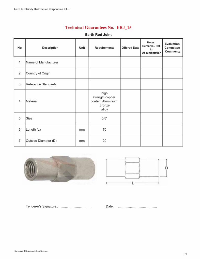
1 Name of Manufacturer
2 Country of Origin
3 Reference Standards
4 Material
highstrength copper
content Aluminium Bronze
alloy
5 Size 5/8"
6 Length (L) mm 70
7 Outside Diameter (D) mm 20
Technical Guarantees No. ERJ_15Earth Rod Joint
Tenderer’s Signature : ……………………..… Date: ………………………………
Studies and Documentation Section1/1

Gaza Electricity Distribution Corporation LTD.
No Description Unit Requirements Offered Data
Notes,Remarks , Ref
toDocumentation
Evaluation Committee Comments
1 Name of Manufacturer
2 Country of Origin
3 Reference Manufacturing Standards
5 Design
Suitable for earth rod 15 mm Dia to
used for connection between Rod and
cable
4 Material Brass
6 Earth Rod Diameter mm 15
7 Copper Cable Cross Section mm2 35-70
Technical Guarantees No. ERC_15Earth Rod Connection Clamp
Tenderer’s Signature : ……………………..… Date: ………………………………
Studies and Documentation Section1/1

Gaza Electricity Distribution Corporation LTD.
No Description Unit Requirements Offered DataNotes, Remarks
, Ref to Documentation
Evaluation CommitteeComments
1 Name of Manufacturer
2 Country of Origin
3 Standards
4 Material 201 Stainless Steel
5 Width mm 12.7
6 Thickness mm 0.76
7 Length m 30
Tenderer’s Signature : ……………………..… Date: ………………………………
Technical Guarantees No. STB_204
Stainless Steel Band
Studies and Documentation Section1/1

Gaza Electricity Distribution Corporation LTD.
No Description Unit Requirements Offered DataNotes, Remarks
, Ref to Documentation
Evaluation Committee Comments
1 Name of Manufacturer
2 Country of Origin
3 Standards
4 Description
Buckle to hold wrapped band
for cable bundling
5 Construction
with teeth and ears provide for
maximum clamping strength
6 Material 201 Stainless Steel
7 Min. Entry Slot High (for Band Thickness 0.76mm) mm 2.3
8 Min. Width (for Band Width 12.7mm) mm 15
Tenderer’s Signature : ……………………..… Date: ………………………………
Technical Guarantees No. STB_254
Stainless Steel Ear-Lokt Buckle
Studies and Documentation Section1/1

Gaza Electricity Distribution Corporation LTD.
No Description Unit Requirements Offered DataNotes, Remarks
, Ref to Documentation
Evaluation CommitteeComments
1 Name of Manufacturer
2 Country of Origin
3 Description Cable Clamps
4 Cable Outer Diameter mm 36-52
5 No. of Cables 1
6 Material Polyamide, Glass Fiber Reinforced
7 Tensile strength N/mm2 120
8 Flexural Strength N/mm2 200
9 Thermal Expansion 0.02% / 1°C
10 Fire Resistance UL 94 , VDE 0304, Part 3
11 Accessories2 Hot Galvanized Bolt with nuts and
washers
12 Dimensions As Drawing
Technical Guarantees No. CC_52Clamp to Holder the Cable (Single , Large )
Tenderer’s Signature : ……………………..… Date: ………………………………
Studies and Documentation Section1/1

Gaza Electricity Distribution Corporation LTD.
No Description Unit Requirements Offered DataNotes, Remarks
, Ref to Documentation
Evaluation Committee Comments
1 Name of Manufacturer
2 Country of Origin
3 Reference Manufacturing Standards
IEC243 , IEC251
4 Description
Environment friendly flame retardant heat shrinkable tube
5 Operating Temperature Co -55 to+125 C
6 Rated Voltage kv 0.6/1
7 Material High Quality Polymer
8 Min. / Max. Cable Outer Diameter mm 16/48
9 Cable Outer Sheath mm PVC or LDPE
10 Dielectric strength KV/mm ≥20
11 Tensile strength Mpa ≥13
12 Tensile strength after aging Mpa ≥11
13 Ultimate Elongation % ≥300
14 Tube Size Before Heating mm 50
15 Tube Size after Heating mm 16
16 Tube Min. Thickness mm 1.2
17 Colour Black
Technical Guarantees No. HST_50/16Flame Retardant Heat Shrinkable Tube with Shrink Ratio 3:1
Tenderer’s Signature : ……………………..… Date: ………………………………
Studies and Documentation Section 1/1
Gaza Electricity Distribution Corporation LTD.
No Description Unit Requirements Offered DataNotes, Remarks
, Ref to Documentation
EvaluationCommitteeComments
1 Name of Manufacturer
2 Country of Origin
3 Standards DIN 4102
4 Material
UV Resistant , UL94 V0 self-extinguishingNatural Nylon
ties
5 Size mm 7.5
6 Length mm 500
7 Max. bundle diameter mm 160
8 Thickness mm 1.8
9 Average opening load daN 65
Tenderer’s Signature : ……………………..… Date: ………………………………
Technical Guarantees No. NCT_50
Natural Nylon Cable Tie 500 mm Long
Studies and Documentation Section1/1

Gaza Electricity Distribution Corporation LTD.
No Description Unit Requirements Offered DataNotes, Remarks
, Ref to Documentation
Evaluation Committee Comments
1 Name of Manufacturer
2 Country of Origin
3 Description Warning Tape
4 Material Low Density Polyethylene
5 Roll Length meter 250
6 Width mm 150
7 Minimum Thickness mm 0.1
English
Arabic
9 Tape Colour PhosphoricYellow
10 Text Colour Dark Black
11 Text Form Big
12 Space Between Text mm 100
13 Resistant Acid / Alkali Resistant
Technical Guarantees No. WT_250Warning Tape
Tenderer’s Signature : ……………………..… Date: ………………………………
8 Printed Legend (2 Language)
CAUTION CAUTION CAUTION Electrical Cables Buried Below
���� ���� ������ ��� � �� ���
Studies and Documentation Section1/1

Gaza�Electricity�Distribution�Corporation�LTD.�����������������������������������������������������������������������������������������������������������Edition:�March/2012�Technical�administration���Planning�Department����������������������������������������������������������������������������������
1��
Studies�and�Documentation�Section�����������������������������������������������������������Eng.�Wael�Ahmed����������������������������������������������������������������������������������������������������������������������
���������������������������������������������
�
�
�
�
�
�
�
�
�
�
�
���� ����������� �� ���� ���������� �������
Gaza�Electricity�Distribution�Corporation��
Technical�Specifications�
For Overhead�Line�Insulators�
�
�
�
March�2012�
�

Gaza�Electricity�Distribution�Corporation�LTD.�����������������������������������������������������������������������������������������������������������Edition:�March/2012�Technical�administration���Planning�Department����������������������������������������������������������������������������������
2��
Studies�and�Documentation�Section�����������������������������������������������������������Eng.�Wael�Ahmed����������������������������������������������������������������������������������������������������������������������
���������������������������������������������
1� Overhead�Line�Insulators��
1.1� General�
Pin,�post�and�reel�type�insulators�shall�be�brown�glazed�porcelain�or�epoxy�resin�and�shall�comply�with�the�requirements�of�adequate�IEC/BS�publications.�
Tension�insulators�shall�be�either�of�strings�of�toughened�glass�disc�insulators�or�comprise�epoxy�resin� long� rod� type�units.� � The�design�of� insulators� and� fittings� shall� be� such� as� to� avoid� local�corona� formation� and� no� significant� radio� interference� shall� be� exhibited.� � The� insulator� units�and� the� complete� insulator� sets� shall� conform� to� the� electrical� and�mechanical� design� criteria�given�in�General�Technical�Specification�of�this�Specification.�
1.2� Pin�Insulators�for�Over�Head�Lines��
Pin�type�insulators�for�use�on�22�kV�lines�shall�have�as�a�minimum�the�electrical�characteris�cs�required� in� General� of� this� Specification� and� they� shall� be� fitted� with� galvanized� mild� steel�spindles�having�a�minimum�failing�load�of�12.5kN.�
Spindles� for�pilot� insulators�must�have�a�minimum�failing� load�of�700N.� �Conductor�sizes�to�be�accommodated�shall�vary�from�6.0mm�to�19.0mm�diameters�with�Preformed�Distribution�Ties.�
1.3� Tension�Insulators�
Tension� insulator� sets� shall� be� either�made�up�of� strings� of� toughened�glass�disc� insulators�of�255mm�diameter�and��xing�centers�at�140mm�of�16mm�ball�and�socket�couplings,�or�of�epoxy�resin�long�rod�type�insulators�of�equivalent�electrical�and�mechanical�performance.�
Complete�tension�insulator�sets,�including���ngs,�shall�have�a�minimum�withstand�factor�of�2.5�based�upon�the�ultimate�mechanical�strength.�
The�ultimate�mechanical�strength�of�an� insulator�set�shall�be�the� load�at�which�any�part�of�the�insulator�string�fails�to�perform�its�function�of�providing�a�mechanical�support�without�regard�to�electrical�failure.�
Individual� insulator� units� shall� have� a� minimum� withstand� factor� of� 2.5� based� upon� the�combined�electro�mechanical�strength�of�the�insulator�unit.�This�is�defined�as�that�load�at�which�any� part� of� the� insulator� fails� to� perform� its� function� either� electrically� or�mechanically�when�voltage�and�mechanical�stresses�are�applied�simultaneously.�
1.4� Marking�of�Insulators��
Each� insulator� shall�have�marked�upon� it� the�manufacturer's�name�or� trade�mark,� the�date�of�manufacture�or� firing,�and� indication�of�the�guaranteed�electro�mechanical�strength�and�other�such�marks�as�may�be�required�to�denote�each�batch�for�the�purpose�of�sample�tests.�
Unless�otherwise�approved� the� insulators� submitted,�as�a�batch� for�a� test� shall�bear� the�same�marks.�
These�marks�shall�be�imprinted�and�not�impressed.�For�porcelain,�the�marks�shall�be�imprinted�before� glazing.� When� a� batch� of� insulators� bearing� a� certain� identification� mark� has� been�

Gaza�Electricity�Distribution�Corporation�LTD.�����������������������������������������������������������������������������������������������������������Edition:�March/2012�Technical�administration���Planning�Department����������������������������������������������������������������������������������
3��
Studies�and�Documentation�Section�����������������������������������������������������������Eng.�Wael�Ahmed����������������������������������������������������������������������������������������������������������������������
���������������������������������������������
rejected�no�further�insulators�bearing�this�mark�shall�be�submitted�and�the�Supplier�shall�satisfy�the�Engineer�that�adequate�steps�will�be�taken�to�mark�or�segregate�the�insulators�constituting�the� rejected� batch� in� such� a�way� that� there� shall� be� no� possibility� of� the� insulators� being� re�submitted�for�test�or�supplied�for�the�use�of�the�Employer.���
1.5� Porcelain�Insulators��
All� porcelain� shall�be� sound,� free� from�defects�and� thoroughly� vitrified.� The�glaze� shall�not�be�depended� upon� for� insulation.� The� glaze� shall� be� smooth,� hard,� of� a� uniform� shade� and� shall�cover�completely�all�exposed�parts�of�the�insulator.�Insulators�and�fittings�shall�be�unaffected�by�atmospheric�conditions�due�to�weather,�proximity�to�the�coast,�fumes,�ozone,�acids�alkalis,�dust�or� rapid� changes� of� air� temperature� between� minus� 40oC� and� plus� 75� oC� under� working�conditions.�
1.6� Insulator�Caps�and�Pins��
The�caps�of� insulator�units�shall�be�of�malleable�cast� iron�or�other�suitable�material�having�the�necessary�strength�to�enable�the�complete�unit�to�comply�with�this�Specification.�The�pins�shall�be�made�of� steel�or�other� suitable�material�of� such�quality� that� the� finished�unit� shall� comply�with�this�Specification.�
The�design�of�the�unit�shall�be�such�that�stresses�due�to�expansion�and�contraction�of�any�part�of�the�insulator�shall�not�lead�to�deterioration.�
The�porcelain�shall�not�engage�directly�with�hard�metal.�Cement�used�in�the�construction�of�an�insulator�shall�not�fracture�by�virtue�of�expansion,�or�loosen�by�contraction�and�proper�care�shall�be�taken�to�locate�the�individual�parts�correctly�during�cementing.�The�cement�shall�not�give�rise�to�chemical�reaction�with�metal�fittings�and�its�thickness�shall�be�as�uniform�as�possible.�
1.7� Fittings��
Ball� and� socket� connections� shall� be� provided� with� specially� designed� a� “W”� clip,� which�effectively� locks� the� connection� against� accidental� uncoupling� without� detracting� from� its�flexibility.�The�"W"�clip�shall�be�of�stainless�steel.�
The�design�shall�be�such�as�to�permit�easy�removal�for�replacement�of�insulator�units�under�live�line�conditions�without�the�necessity�of�removing�the�entire�string�from�the�cross�arm.�All�split�pins�for�securing�the�attachment�of�fittings�of�insulator�sets�shall�be�of�stainless�steel�and�shall�be�backed�by�washers.�Plated�split�pins�shall�not�be�used.�
1.8� Composite�insulators�
The� insulator� shall� be�made�of� composite�materials� of� high� resistance� to�moisture,� ultraviolet�radiation,�high�temperatures�and�tropical�sunshine�conditions.�The�core�shall�be�made�of�resin�impregnated�glass�fibres�free�from�defects.�The�housing�of�the�insulator�shall�be�manufactured�from� high� quality� silicone� rubber� according� international� standards� and� all� necessary�specifications�attached�in�technical�guarantees.�
The� under� surface� and� grooves� of� sheds� or� skirts� shall� be� easy� cleaning.� Sheds� shall� be�substantially�symmetrical�in�shape�without�appreciable�warping.��
Gaza�Electricity�Distribution�Corporation�LTD.�����������������������������������������������������������������������������������������������������������Edition:�March/2012�Technical�administration���Planning�Department����������������������������������������������������������������������������������
4��
Studies�and�Documentation�Section�����������������������������������������������������������Eng.�Wael�Ahmed����������������������������������������������������������������������������������������������������������������������
���������������������������������������������
�
1.9���������SHACKLE�INSULATOR�
The�shackle�insulator�shall�be�manufactured�and�tested�in�accordance�with�the�latest�version�of�international�standards�that�ensures�at�least�equal�or�better�quality�to�the�standard�mentioned�above,�will�also�be�acceptable.�
���������������������� The�shackle�insulator�shall�have�following�ratings�and�features:�
�� Highest�System�Voltage�1�kV�
�� Power�Frequency�Withstand�Voltage�,1�minute:�Dry�25�kV,�Wet�12�kV�
�� Power�Frequency�Puncture�Withstand�voltage,�1�minute:�1.3�x�actual�dry��ashover�voltage�
��Mechanical�Strength�13�kN�
The�shackle�insulator�shall�including�U���Bracket,�Nail�&�Buckle�and�Steel�Bolt�
The�dimensions�shall�be�as�attached�drawings�with�technical�guarantees�
1.10� Ferrous�Metal�Parts��
All� ferrous�metal�parts�except�those�of�stainless�steel�shall�be�hot�dipped�galvanized�to�give�an�average�coa�ng�of�zinc�equivalent�to�610�grams�per�square�meter.�
1.11���������Quality�Assurance�
The�manufacturer�of�insulator�and�hardware�components�shall�have�obtained�quality�assurance�cer��ca�on�conforming�to�ISO�9002�for�the�manufacture�of�same�and�the�bidder�shall�furnish�documentary�evidence�with�the�offer�to�prove�this.�
1.12�������Tests�
Design�tests,�type�tests,�sampling�tests�and�routine�tests�shall�be�done�in�accordance�with�the�requirement�of�IEC�1109,�IEC�383,�IEC�575,�BS137,�ISO�1460�and�the�requirements�of�this�specification.�It�shall�be�the�responsibility�of�the�manufacturer�to�perform�or�to�have�performed�all�the�tests�specified.�
Certified�true�copies�of�previous�design�and�type�test�reports�by�the�relevant�Independent/International�or�National�Testing/Standards�Authority�of�the�country�of�manufacture�(or�ISO/IEC�17025�accredited�laboratory)�shall�be�submi�ed�with�the�oer�for�evaluation�(all�in�English�Language).�A�copy�of�accreditation�certificate�for�the�laboratory�shall�also�be�submitted.�
Copies�of�test�reports�for�the�following�Design�and�Type�Tests�shall�be�submitted�for�tender�evaluation:�
Tests�on�interfaces�and�connections�of�metal�fittings��
� Assembled�core�load�time�test��

Gaza�Electricity�Distribution�Corporation�LTD.�����������������������������������������������������������������������������������������������������������Edition:�March/2012�Technical�administration���Planning�Department����������������������������������������������������������������������������������
5��
Studies�and�Documentation�Section�����������������������������������������������������������Eng.�Wael�Ahmed����������������������������������������������������������������������������������������������������������������������
���������������������������������������������
� Test�of�housing:�tracking�and�erosion�test.�The�test�reports�MUST�include�resistance�to�ageing�tests�(under�climate�chambers�to�mimic�the�conditions�–�sunshine,�salinity,�temperature,�humidity,�spray�and�so�on�–�typical�of�tropical�climate�in�addition�to�the�highest�system�voltage);�
� Tests�for�the�core�material��
� Flammability�test��
� Dry�lightning�impulse�withstand�voltage�test��
� Wet�power�frequency�test��
� Mechanical�load�time�test�and�test�of�the�tightness�of�the�interface�between�end�fittings�and�insulator�housing.�
1.13�������ADDITIONAL�REQUIREMENTS�
1.13.1�����Identification�
Each�insulator�shall�be�marked�with�the�following�information�and�the�marking�shall�be�legible�and�indelible.�
a)�Manufacturer's�identification�
b)�Minimum�failing�load�kN�.�
c)�Year�of�manufacture.�
The�manufacturer’s�identification�mark�shall�be�indelibly�marked�before�galvanizing�on�all�the�hardware�components�of�the�string�insulator�sets.�
1.13.2�����Packing�
The�String�Insulators�and�the�Hardware�shall�be�packed�separately�in�palletized�wooded�boxes��
1.14��������INFORMATION�TO�BE�SUPPLIED�WITH�THE�OFFER�
The�following�shall�be�furnished�with�the�Offer.�
a)�Catalogues�describing�the�item�and�indicating�Model�No.�
b)�Constructional�features,�materials�used�for�components.�
c)�Complete�dimensional�drawings.�
d)�Certificate�of�type�tests�carried�out�in�accordance�with�the�specified�standard�by�an�acceptable�tes�ng�authority.�Test�cer��cates�should�cover�all�the�tests�in�group�1�(type�test)�of�BS�137�Part�1:�1993,�IEC�1109�and�IEC�383�(1993).�Test�Cer��cates�shall�be�given�for�String�Insulator�Units�as�well�as�for�complete�Suspension�and�Tension�Insulator�sets.�
In�addition�Type�Test�Certificates�for�the�string�insulator�units�shall�include�thermal�mechanical�performance�test�as�per�IEC�575�(1977)�

Gaza�Electricity�Distribution�Corporation�LTD.�����������������������������������������������������������������������������������������������������������Edition:�March/2012�Technical�administration���Planning�Department����������������������������������������������������������������������������������
6��
Studies�and�Documentation�Section�����������������������������������������������������������Eng.�Wael�Ahmed����������������������������������������������������������������������������������������������������������������������
���������������������������������������������
e)�Quality�Assurance�Certification�conforming�to�ISO�9002�for�the�manufacturer�of�insulators�as�well�as�hardware�components.�
f)�The�particulars�requested�in�Annex���B.�
g)�A�list�of�names�and�addresses�of�five�leading�purchasers�outside�the�country�of�origin�(to�whom�the�manufacturer�have�supplied�the�insulators�of�similar�or�higher�voltage�rating�),�giving�dates�of�delivery�and�quantities�supplied�during�the�past�five�years.�
Failure�to�furnish�these�particulars�will�result�in�the�tender�being�rejected.�
1.15�������SAMPLE�AND�ROUTINE�TEST�
Following�test�shall�be�witnessed�by�the�Engineer�nominated�by�the�GEDCo.�Extra�copies�of�these�test�certificates�shall�also�be�supplied�with�the�equipment.�
1.15.1�����Sample�Test�
Verification�of�the�locking�system�(Ball�&�Socket�Couplings)�
Verification�of�the�dimensions�
�Verification�of�the�displacements�
Temperature�cycle�test�
Electro�mechanical�failing�load�test�
Mechanical�failing�load�test�
Thermal�shock�test�(on�toughened�glass�Insulators�only)�
Puncture�test�
Porosity�test�(on�Porcelain�Insulators�only)�
Galvanizing�Test�
1.15.2�����Rou�ne�Test�(as�per�Clause�34�of�IEC�383�1983)�
The�following�routine�test�reports�shall�be�made�available�for�the�observation�of�the�GEDCo�Inspector�at�the�time�of�inspection�
1)�Electrical�routine�test�
2)�Mechanical�routine�test�
3)�Visual�examination�

Gaza Electricity Distribution Corporation LTD.
No Description Unit Requirements Offered Data
Notes, Remarks , Ref
to Documentation
Evaluation Committee Comments
1 Name of Manufacturer
2 Country of Origin
3 Design Standards IEC 61109 , IEC 60815
4 Nominal System Voltage kV 24
5 Type Pin Type
6 Insulating Material Composite Polymer
7 Housing Silicon
8 Metal Parts Hot Dip Galvanized
9 Number of Sheds
10 Total Length (L) mm
11 Shed Diameter mm
12 Min. Creepage Distance mm 1050
13 Cantilever Strength KN 12.5
14 Total Weight Kg
15.1 a) Dry kV 85
15.2 b) Wet kV 70
15.3 c) Impulse +VE & -VE kV
16.1 a) Power Frequency (Dry) kV 125
16.2 b )Power Frequency (Wet) kV 95
16.3 c) Impulse +VE & -VE kV r215
Technical Guarantees No. PPYI_1050
22kv Overhead Line Pin Type Polymer Insulator with Creepage Distance 1050 mm
15- Power Frequency withstand Voltage (1 min)
16- Flashover Voltage
Studies and Documentation Section1/2

Gaza Electricity Distribution Corporation LTD.
No Description Unit Requirements Offered Data
Notes, Remarks , Ref
to Documentation
Evaluation Committee Comments
Technical Guarantees No. PPYI_1050
22kv Overhead Line Pin Type Polymer Insulator with Creepage Distance 1050 mm
17.1 Pin Diameter (stud) mm 25
17.2 Pin Not_Toothed Part Length mm 70
17.3 Pin Toothed Part Length mm 70
17.4 The Top slot Diameter mm 24
17.5 Pin Accessories Nuts and Washers
18Type Test Certificates/Reports from internationally reputed testing agency
Required
19 Dimensions as Below Drawing
17- Fittings
Tenderer’s Signature : ……………………..… Date: ………………………………
70mm
Studies and Documentation Section2/2

Gaza Electricity Distribution Corporation LTD.
No Description Unit Requirements Offered Data
Notes, Remarks , Ref
toDocumentation
Evaluation Committee Comments
1 Name of Manufacturer
2 Country of Origin
3 Design Standards BS137& IEC60120
5 Insulator material Glass
6 Min. Mechanical Failing Load kN 70
8 Weight Kg
9 Creepage Distance mm 320
10 Diameter mm 255
11 Ball Size mm �16
12 Dimensions as Below Drawing
13.1 a)Dry kV 70
13.2 b)Wet kV 40
13.3 c)Positive Dry Impulse +VE kV 100
13.4 d)Negative Dry Impulse -VE kV 103
14 Min Puncture Voltage in Oil kV 130
15 Phosphorous Bronze Security Clip (BS 3288 Part 4) W-CLIP
Technical Guarantees No. GDI_320
22kv Overhead Line Toughened Tension Glass Disk Insulator with Ball and Socket
13- Power Frequency withstand Voltage ( 1min)
Studies and Documentation Section1/2

Gaza Electricity Distribution Corporation LTD.
No Description Unit Requirements Offered Data
Notes, Remarks , Ref
toDocumentation
Evaluation Committee Comments
Technical Guarantees No. GDI_320
22kv Overhead Line Toughened Tension Glass Disk Insulator with Ball and Socket
16 Accessories Hot Galvanized Ball and Socket
Tenderer’s Signature : ……………………..… Date: ………………………………
Studies and Documentation Section2/2
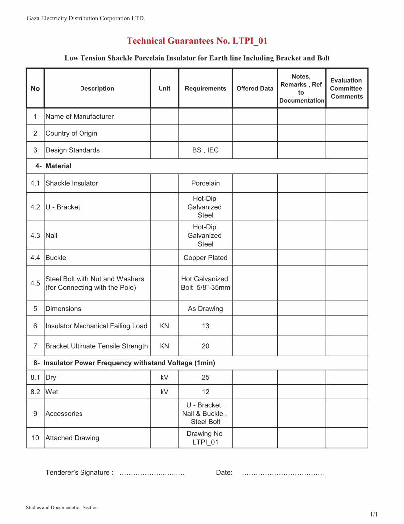
Gaza Electricity Distribution Corporation LTD.
No Description Unit Requirements Offered Data
Notes, Remarks , Ref
toDocumentation
Evaluation CommitteeComments
1 Name of Manufacturer
2 Country of Origin
3 Design Standards BS , IEC
4.1 Shackle Insulator Porcelain
4.2 U - BracketHot-Dip
Galvanized Steel
4.3 NailHot-Dip
Galvanized Steel
4.4 Buckle Copper Plated
4.5 Steel Bolt with Nut and Washers (for Connecting with the Pole)
Hot Galvanized Bolt 5/8"-35mm
5 Dimensions As Drawing
6 Insulator Mechanical Failing Load KN 13
7 Bracket Ultimate Tensile Strength KN 20
8.1 Dry kV 25
8.2 Wet kV 12
9 Accessories U - Bracket ,
Nail & Buckle , Steel Bolt
10 Attached Drawing Drawing No LTPI_01
Technical Guarantees No. LTPI_01
Low Tension Shackle Porcelain Insulator for Earth line Including Bracket and Bolt
4- Material
8- Insulator Power Frequency withstand Voltage (1min)
Tenderer’s Signature : ……………………..… Date: ………………………………
Studies and Documentation Section1/1

�
H D d d1 R76 89 48 17.5 10
LTPI_01

Gaza�Electricity�Distribution�Corporation�LTD.�����������������������������������������������������������������������������������������������������������Edition:�March/2012�Technical�administration���Planning�Department����������������������������������������������������������������������������������
1��
Studies�and�Documentation�Section�����������������������������������������������������������Eng.�Wael�Ahmed����������������������������������������������������������������������������������������������������������������������
���������������������������������������������
�
�
�
�
�
�
�
�
�
�
�
���� ����������� �� ���� ���������� �������
Gaza�Electricity�Distribution�Corporation��
Technical�Specifications�
For�Surge�Arresters�
�
�
� March�2012�

Gaza�Electricity�Distribution�Corporation�LTD.�����������������������������������������������������������������������������������������������������������Edition:�March/2012�Technical�administration���Planning�Department����������������������������������������������������������������������������������
2��
Studies�and�Documentation�Section�����������������������������������������������������������Eng.�Wael�Ahmed����������������������������������������������������������������������������������������������������������������������
���������������������������������������������
1� Metal�Oxide�Surge�Arresters�gap�less�Type�for�22KV�Network�with�Silicon�Polymeric�housing�
������������������SCOPE�
These�specifications�cover�the�minimum�technical�requirements�for�the�design�manufacture.�Supply�and�transportation�to�the�site(s)�and�testing�of�Metal�Oxide�surge�Arrestors�gap�less�type�with�silicon�polymer�housing�for�outdoor�installation�in�the�22KV�distribution�system.�
�
1.1������������STANDARDS�
The�latest�revision�of�the�following�codes�and�standards�shall�be�applicable�for�the�equipment/material�covered�in�this�specification.�In�case�of�any�deviation,�the�vendor/manufacture�may�propose�equipment/material�conforming�to�an�alternate�code�or�standard.�
1. ANSI�C62.1�Standard�specification�for�surge�arrester�for�AC�power�circuit.�
2. NEMA�LA1�Standard�specification�for�Surge�Arresters.�
3. IEC�60099�4�Standard�specification�for�non�linear�resistor�type�arrester�for�A.C.�system.�
4. IEC�TC37��Standard�specification�for�metal�oxide�type�arrester�with�Part�3(wg�4)�out�spark�gaps.�
5. IEC�168�Insulators.�
6. BS�729�Galvanizing.�
�
1.2������������RATINGS�AND�PERFORMANCE/GENERAL��
3.1�Rating,�performance�and�testing�of�each�product�shall�meet�the�requirements�described�in�the�relevant�clauses.��
3.2�The�specified�ratings�and�the�minimum�guaranteed�performance�shall�be�for�the�distribution�system�and�service�conditions�described�in�clause�1.��
3.3�All�materials�used�in�the�construction�of�the�Surge�Arrestor�shall�be�capable�of�withstanding�mechanical,�electrical�and�thermal�stresses�developed�during�the�normal�working�(permanent�or�temporary�loading),�short�circuit�and�emergency�overloading�under�the�service�conditions�described�in�General�Specifications.�
�
1.3����������Design�
The�Arrestors�shall�be�capable�of�protecting�the�following�equipment:�
� Transformers�which�are�directly�connected�to�a�line�
� Transformers�which�are�connected�to�a�line�via�cables�

Gaza�Electricity�Distribution�Corporation�LTD.�����������������������������������������������������������������������������������������������������������Edition:�March/2012�Technical�administration���Planning�Department����������������������������������������������������������������������������������
3��
Studies�and�Documentation�Section�����������������������������������������������������������Eng.�Wael�Ahmed����������������������������������������������������������������������������������������������������������������������
���������������������������������������������
� Capacitors�
� Cables��
� Autoreclosers�and�sectionalisers�
� Circuit�breakers�and�isolators�
� Instrument�transformers�
�
The�Surge�Arrestors�shall�be�of�the�metal�oxide�gap�less�type,�complying�with�IEC�60099�4.�
�
The�Surge�Arrestors�shall�have�the�following�characteristics:�
Description� Unit� Guaranteed�Data�
Rated�Voltage�� kV� 24�
Maximum�continues�operating�voltage�(M.C.O.V)� kV� 19.5�
Nominal�discharge�current����(8/20�μs)�� kA� 10�
Class�Distribution�Min.�protective�ratio� �� 1.2�
�
The�Arrestors�shall�be�designed�horizontally�or�vertically�(standing�or�hanging)�in�standard�lattice�towers.�The�Arrestors�shall�be�supplied�complete�with�fixing�materials�and�connection�clamps.�
�
Surge�Arrestor�distribution�classes�shall�be�as�defined�in�IEC�60099�4,�10KA�Arrestor�heavy�duty�class�
The�Surge�Arrestors�shall�be�fitted�with�a�pressure�relief�device.�
�
All� Arrestors� shall� be� fitted� with� in� corrodible� metal� nameplates� which� are� visible� when� the�Arrestor�is�completely�mounted�and�which�clearly�indicate�the�data�specified�in�IEC�in�engraved�or�embossed�characters.��
�
1.4���������Protection�Characteristics�
This�is�a�combination�of�the�following:��
� Maximum�residual�voltage�for�steep�current��impulse�(1/20�μs)�
� Maximum�residual�voltage�for�current�impulses�with�waveform�(�8/20�μs)�and�0.5,�1.0�and�2.0�times�nominal�current�
� Maximum�residual�voltage�for�switching�impulse�(30�100/60�200�μs)�

Gaza�Electricity�Distribution�Corporation�LTD.�����������������������������������������������������������������������������������������������������������Edition:�March/2012�Technical�administration���Planning�Department����������������������������������������������������������������������������������
4��
Studies�and�Documentation�Section�����������������������������������������������������������Eng.�Wael�Ahmed����������������������������������������������������������������������������������������������������������������������
���������������������������������������������
� The�protection�level�for�lightening�impulse�is�the�highest�of��
������������������������������Maximum�residual�voltage�for�steep�current�impulse�divided�by�1.15�
������and�
������Maximum�residual�voltage�at�nominal�current�and�8/20�μs�
The� protection� level� for� switching� impulse� is� the� maximum� residual� voltage� at� the�specified�switching�impulse�current.�
The�protection�level�shall�have�at�least�a�margin�of�safety�of�30�%�compared�to�the�BIL�of�the�Arrestor�housing.�
�
1.5���������Energy�Requirements�
� The�Surge�Arrestors�shall�be�designed�to�minimum�line�discharge�class�1�according�to�IEC�60099�4�for�heavy�duty�Arrestors.�
�
1.6����������CONSTRUCTION�DETAILS��
The�surge�Arrestors�shall�be�designed�for�outdoor�service�and�for�installation�between�phase�and�earth.�The�surge�Arrestors�shall�be�composed�of�on�or�several�series�connected�units.�The�surge�Arrestors�unite�shall�be�interchangeable�with�like�rated�units�to�the�same�type�and�design.�The�active�part�of�the�surge�Arrestors�shall�consist�of�one�or�more�non�linear�metal�oxide�resistors,�connected�in�series�and/or�parallel�but�having�no�integrated�series�or�parallel�spark�gaps.�
The�construction�consists�from�these�layers:�
1.6.1�������Housing:�
The�outer�housing�shall�be�of�a�silicone�rubber�material�offering�high�resistance�to�pollution.�The�specific�creepage�distance�for�any�Arrestor�shall�be�910mm,�corresponding�to�heavy�pollution�according�to�IEC.��
The�internal�part�of�the�surge�Arrestors�shall�be�enclosed.�
Polymeric�insulator�designed�to�withstand�the�environmental�conditions.�
The�insulators�shall�meet�the�requirements�and�test�requirements�described�in�the�relevant�IEC�standards.��
�
1.6.2���������Over�Pressure�Relief�Device:�
Arrestor�shall�be�provided�with�a�pressure�relief�device,�a�mean�for�relieving�internal�pressure�in�an�Arrestor�and�preventing�explosive�shattering�of�the�housing�following�prolonged�passage�of�flow�current�or�internal�flashover�of�the�Arrestor.�
1.6.3��������Disconnection�Feature:�
Disconnector�shall�be�incorporated.��It�is�a�device�for�disconnecting�an�Arrestor�from�the�system�in�the�event�of�Arrestor�failure�to�prevent�a�persistent�fault�on�the�system�and�to�give�visible�

Gaza�Electricity�Distribution�Corporation�LTD.�����������������������������������������������������������������������������������������������������������Edition:�March/2012�Technical�administration���Planning�Department����������������������������������������������������������������������������������
5��
Studies�and�Documentation�Section�����������������������������������������������������������Eng.�Wael�Ahmed����������������������������������������������������������������������������������������������������������������������
���������������������������������������������
indication�of�the�failed�Arrestor.�The�method�of�operation�of�Disconnector�shall�be�described�by�supplier.�
�
1.6.4��������Terminals:�
The�surge�Arrestors�shall�be�furnished�with�two�parallel�vertical�flat�terminal�connection�pads�suitable�for�connection�to�the�Medium�voltage�system�made�of�copper�for�connection�similarly�with�a�horizontal�pad�for�grounding.���
1.6.5��������Galvanizing:�
Exposed�iron�and�steel�parts�shall�be�hot�dip�galvanized�according�to�any�proposed�international�standards.�The�average�thickness�of�the�coating�except�for�small�parts�shall�be�50�μm.�
1.6.6�������ACCESSORIES:�
1)�Disconnector.��
2)�Earth�Lead�Disconnector�12mm.���
3)Bird�Cap�
4)Bracket�
5)�Earth�lead�Cable�Cross�Section�70�mm2�and�shall�be�Extra�Flexible�PVC�Insulated�Copper�(Multi�Stranded�Wires�according�to�DIN�VDE�0295�Class5)��
1.7��������DIAGRAMS�AND�DRAWINGS��
The�following�diagrams�and�drawings�shall�be�submitted�with�the�tender�as�a�part�of�the�tender�documents.���
��Complete�sets�of�detailed�dimension�drawings�and�catalogues�of�the�offered�products.���
��Calculation�sheets�for�construction.���
��Other�necessary�drawings�(open�view�for�complete�surge�Arrestors).���
The�Contractor�shall�submit�detailed�working�drawings�together�with�the�calculations�justifying�their�use�as�soon�as�possible�after�elaboration�of�the�contract,�instruction�document�for�maintenance,�installation�and�putting�in�operation�of�the�equipment.���
�
1.8�������TESTING�
The�offered�products�shall�be�tested�in�accordance�with�the�standards�and�specifications�mentioned�in�IEC�60099�4�Standard.�
If�type�tests�have�been�already�affected�by�an�independent�testing�authority,�the�type�test�reports�and�certificates�shall�be�enclosed�with�the�tender.�
The�offerer�shall�supply,�on�request,�copies�of�the�type�test�certificates�for�the�raw�materials�used.�
The�contractor�shall�provide�GEDCO�with�a�schedule�of�proposed�tests�to�be�carried�out�together�with�copies�in�English�of�all�testing�standards�and�procedures�including�electric���drawings,�diagrams�and�data�curves,�measuring�method�and�all�required�and�useful�information.�

Gaza�Electricity�Distribution�Corporation�LTD.�����������������������������������������������������������������������������������������������������������Edition:�March/2012�Technical�administration���Planning�Department����������������������������������������������������������������������������������
6��
Studies�and�Documentation�Section�����������������������������������������������������������Eng.�Wael�Ahmed����������������������������������������������������������������������������������������������������������������������
���������������������������������������������
Test�certificates�shall�include�in�addition�to�test�results:�
�������(a)�The�manufacturer’s�number.�
�������(b)�The�date�of�testing.���
�������(c)�The�signature�of�the�test�engineer.�
Routine�Test:�
Supplier�shall�provide�detail�of�the�routine�tests,�which�will�be�performed�on�the�arresters�with�the�minimum�requirement�being�following.�
�Leakage�current�test:���Measurement�of�the�leakage�current�of�the�arresters�at�voltage�to�100%,�80%�and� 60�% of�the�rated�voltage.�
1)�Power�frequency�reference�or�low�current.�
2)�Residual�voltage�test.�
3)�Insulator�tests.�
�
1.9�����PACKING�AND�SHIPMENT:��
The�type�of�packing�should�be�suitable�for�export�and�provide�complete�protection�for�marine�or�truck�or�rail�transportation�and�for�loading,�for�example�(boxes,�cases,�etc…)�should�be�robust�enough�and�have�suitable�dimensions�and�weights.��
Tenderer�will�take�care�on�his�own�account�that�the�commodity�will�be�packed�carefully�in�order�to�avoid�damage�of�delivered�materials�and�to�be�acceptable�to�the�insurance�company.���
The�strength�and�quality�of�the�packing�materials�should�correspond�to�the�weight�of�the�packed�materials.���
Appropriate�measures�according�to�each�commodity�type�shall�be�taken�to�prevent�vibration,�sliding�or�movement�inside�boxes�or�cases.����
Boxes�which�should�be�handled�with�care�according�to�the�contents�must�be�marked�accordingly�and�clearly.����
Sufficient�steel�bands�for�boxes�shall�be�in�accordance�with�their�weight�and�dimensions,�sensitive�instruments�and�similar�materials�must�be�packed�carefully�to�prevent�exposure�of�elements�to�rain,�sun,�dust,�etc…�with�the�appropriate�packing�of�nylon�bags�oiled�paper�and�foam�materials.���
Packing�list:�each�case�must�contain�equipment�of�the�same�kind�and�their�accessories.���
Each�case�must�include�the�packing�list�fixed�on�the�case�and�protected�in�addition�to�the�list�inside�the�case.���
�
�
1.10���MARKING�AND�IDENTIFICATION��
GEDCO�stresses�great�importance�on�distinct�and�durable�identification.��
Arrestor�identification:�

Gaza�Electricity�Distribution�Corporation�LTD.�����������������������������������������������������������������������������������������������������������Edition:�March/2012�Technical�administration���Planning�Department����������������������������������������������������������������������������������
7��
Studies�and�Documentation�Section�����������������������������������������������������������Eng.�Wael�Ahmed����������������������������������������������������������������������������������������������������������������������
���������������������������������������������
���������Metal�oxide�surge�Arrestors�shall�be�identified�by�the�following�minimum�information���
���������which�shall�appear�on�a�nameplate�permanently�attached�to�the�Arrestor:���
����������continuous�operating�voltage.���
����������rated�voltage.���
���������nominal�discharge�current.���
���������the�manufacturer’s�name�or�trade�mark,�type�and�identification�of�the�complete�Arrestor.���
���������identification�of�the�assembling�position�of�the�unit�(for�multi�unit�Arrestors�only).���
���������the�year�of�the�manufacture.���
���������GEDCO,�the�purchaser.���
Note�–�If�sufficient�space�is�available�the�nameplate�should�also�contain:���
*�line�discharge�class�or�high�lightning�duty�type.���
*�contamination�withstand�level�of�the�enclosure,�see�IEC�815.�
It�is�important�to�mark�each�case�or�box�clearly�by�the�following:���
��������contract�number.���
��������GEDCO,�the�purchaser.���
��������delivery�number,�shipment�number.���
��������manufacturing�date.���
��������name�of�manufacturer.���
��������kind�of�materials.���
��������quantities�contained.���
��������main�technical�specification.���
��������gross�weight,�net�weight.���
��������item�number.���
�
The�marking�must�be�clear�and�written�on�two�sides�of�the�box�with�unerasable�materials.����
�
�
�
�

Gaza Electricity Distribution Corporation LTD.
No Description Unit Requirements Offered DataNotes, Remarks
, Ref to Documentation
Evaluation Committee Comments
1 Name of Manufacturer
2 Country of Origin
3 Standards ANSI C62.1 / IEC60099_4
4 Surge arrester Type
10kA Heavy Zinc Oxide Duty
Polymer Gap-Less
5.1 Ambient air temperature -10 oC to 55oC
5.2 Temperature with solar radiation 65 oC
5.3 Installation Outdoor
5.4 Type of installation Phase to earth
5.5 Nominal syst. Voltage between phases kV 22
5.6 Max. syst. Voltage between phases kV 24
5.7 Rated Frequency Hz 50
6 Impulse withstand Voltage 1,2/50 �s kV 125
7 Maximum continues operating voltage (M.C.O.V) kV 19.5
8.1 a) For 1 sec. kV
Technical Guarantees No. SA_19
Metal-Oxide Surge Arresters gap-less Type for 22KV Network With Silicon-Polymeric housing
5- Service Conditions
8- Temporary overvoltages: Utov
Studies and Documentation Section1/3

Gaza Electricity Distribution Corporation LTD.
No Description Unit Requirements Offered DataNotes, Remarks
, Ref to Documentation
Evaluation Committee Comments
Technical Guarantees No. SA_19
Metal-Oxide Surge Arresters gap-less Type for 22KV Network With Silicon-Polymeric housing
8.2 b) For 10 sec. kV
9submit arrester curves of Utov as function of their duration at 40-60 °C ambient temperature
Should be submitted
10 Nominal discharge current (8/20μs) In
kA peak 10
11 Partial discharge at 1.05 Uc 5 pc
12 Arrester housing Material High quality
Silicon-Polymeric
13 Creepage Distance mm 910
14
Equivalent Front-of-Wave (maximum discharge voltage for a 10 kA impulse current wave which produces a voltage wave cresting in 0.5 �s.)
kV Crest 88
15.1 a) 2.5 KA kV 65
15.2 b) 5 KA kV 70
15.3 c) 10 KA kV 75
15.4 c) 20 KA kV 80
16.1 a) High current impulse 4/10μs KA peak 100
16.2 b) Long duration current 200μs A peak 250
15- Max. Discharge Voltage Using an 8/20 �s Current Impulse
16- Discharge current withstand
Studies and Documentation Section2/3

Gaza Electricity Distribution Corporation LTD.
No Description Unit Requirements Offered DataNotes, Remarks
, Ref to Documentation
Evaluation Committee Comments
Technical Guarantees No. SA_19
Metal-Oxide Surge Arresters gap-less Type for 22KV Network With Silicon-Polymeric housing
17 All Test reports for all materials of surge arrester
should be submitted
18.1 a) Disconnector Required
18.2 b) Brackets Required
18.3 c) Bird cap Required
18.4 b) Earth lead Required
18.4.1 Earth lead Cable Material
Extra Flexible PVC Insulated Copper (Multi
Stranded Wires according to
DIN VDE 0295 Class5)
18.4.2 Earth lead Cable Length m 0.5
18.4.3 Earth lead Cable Cross Section mm2 70
18.4.4 Suitable 2 Each Compression lug with 13 mm Hole for Earth Lead Required
19
Type Test Certificates /Reports from internationally reputed testing agency (According IEC 60099-4)
Required
20 Attached Drawing Drawing No SA_19
18- Additional equipment & fittings:
Tenderer’s Signature : ……………………..… Date: ………………………………
Studies and Documentation Section3/3