Embed Size (px)
Citation preview
Degree Final Project in Industrial Engineering
ANLYSIS OF ELECTRICITY
STORAGE USING
COMPRESSED HYDROGEN
AUTHOR: Joan Josep Garrigós Sempere
SUPERVISOR: Rodolfo Taccani
TECHNICAL DIRECTORS: Paolo Pinamonti and Federico Ustolin
Academic Year 2017-2018

ANALYSIS OF ELECTRICITY STORAGE USING COMPRESSED HYDROGEN
1
GREETINGS
Thanks to Rodolfo, Paolo and Federico.
Thanks to my family.
Thanks to my friends.
But, mostly thanks to this Erasmus in Trieste, full of experiences, full of problems.
Incredibles. Specials.
It is just the beginning...

ANALYSIS OF ELECTRICITY STORAGE USING COMPRESSED HYDROGEN
2
ABSTRACT
The study is focused in the hydrogen as the new energy vector for the future, and
how it can make a reality the introduction of the renewables in the future energy system.
Being concerned about the problem that al the population suffer with the
contamination, the renewables are a solution, but them must be introduced by a firm
storage system that equilibrates the equation between production and demand of
electricity.
Our bet is the hydrogen, for this reason in this work we have developed a model
of electrolyzer powered by the electricity produced in a solar panel. First of all, the work
starts with a rehearsal about the different types of storage that exists and why the hydrogen
is the most suitable one.
After that, we realized a model of the electrolyzer and once the model is working,
we test it in an alleged situation which the electrolyzer must covered the electric daily
demand of a house.
ANALYSIS OF ELECTRICITY STORAGE USING COMPRESSED HYDROGEN
3
INDEX
1. INTRODUCTION
2. STORAGE ELECTRICITY SYSTEMS
2.1. Storage in Mechanichal energy
2.1.1. Potential or positional energy
2.1.2. Kinetic energy
2.1.3. Compression energy
2.2. Electromagnetic energy
2.3. Thermal energy
2.4. Chemical energy
2.4.1. Chemical combustion energy
2.4.2. Electrochemical energy
2.4.2.1. Lead-acid batteries
2.4.2.2. Batteries with alkaline electrolyte
2.4.2.3. Lithium ion batteries
2.4.2.4. Hydrogen in an electrochemical device
3. HYDROGEN AND ELECTROLYSER
3.1. Hydrogen, the Element
3.2. The Cycle of Hydrogen
3.2.1. Electrolysis of water
3.2.1.1. Alkaline electrolyzer
3.2.1.2. PEM Electrolyzer
3.2.1.3. High temperature Electrolyzer
3.2.2. The storage of Hydrogen
3.2.3. Hydrogen applications
3.3. Present and development of Hydrogen in industry
4. THE MODEL OF ELECTROLYSER
4.1.Theorical development of the model
4.2. Commercial electrolyzers
4.3. Comparison of the model

ANALYSIS OF ELECTRICITY STORAGE USING COMPRESSED HYDROGEN
4
5. ELECTROLYSIS TO COVER AN ELECTRICAL DEMAND
5.1.The daily electrical demand of a house
5.2.The command in MATLAB
5.3.Example to show the working mode
6. RESULTS AND CONCLUSIONS
7. ANNEXES
7.1.Electrolyzer model
7.2.Demand model
8. REFERENCES
ANALYSIS OF ELECTRICITY STORAGE USING COMPRESSED HYDROGEN
5
INDEX OF FIGURES
- Figure 1. Hydroelectric scheme during the day
- Figure 2. Compression storage scheme
- Figure 3. Electromagnetic storage scheme
- Figure 4. Battery diagram of working
- Figure 5. Energy Density of Fuel
- Figure 6. Schematic operation of electrolysis
- Figure 7. Comparative scheme between alkaline and PEM electrolysis
- Figure 8. Types of Fuel Cells
- Figure 9. Cell polarization curve
- Figure 10. Comparison between model and commercial electrolyzers
- Figure 11. Daily electrical and thermal monthly profile
- Figure 12. Isotherms of an ideal gas
- Figure 13. Hydrogen needed to cover an electrical demand of a house
- Figure 14. Level of pressure to store the hydrogen
ANALYSIS OF ELECTRICITY STORAGE USING COMPRESSED HYDROGEN
6
1. INTRODUCTION
The world is in constant change, it is a fact. And like it, everything that surrounds it.
However, not all changes are moving at the same speed. In the last years, we have
observed how the technological world has experienced exceptional changes, as is the case
in the field of telecommunications, with the emergence of the Internet. Nevertheless,
related to the energy system, it has always been focused on the same materials, such as
coal, natural gas and petroleum products. But will it continue for much longer? Of course
not.
It is not new to highlight the results of all environmental impact studies carried out on
the use of this type of fuel. Where everyone has reached the same conclusion, such climate
change as dust deflection, or as phenomena such as acid rain, are partly related with the
gases that are produced in the combustion of these fuels. The known ones as greenhouse
gases.
For this reason, for many years international governments have been implemented
environmental plans to reduce the emission taxes of these gases, as well as plans to
incorporate renewable energies into the energy market. Most of them without success,
which has made the petroleum industry continue to lead the energy production.
Nowadays, to the polluting point and little respectful with the environment, we must
add the point that it is a finite resource. This fact, coupled with the great environmental
impact they have caused, has generated the great increase in the importance of
incorporating renewable energies into the current energy system.
But the generation of energy, specifically electricity from renewable, unfortunately is
not a constant process, unlike the case of fuel burners in which we only need to burn fuel
to produce energy. That point of fluctuation is due to the fact it depends on external factors
such as wind in wind power stations or solar radiation in solar plants. That is why another
factor of reinforcement must be introduced in this fluctuating situation, to give stability
to the equation of electricity generation and consumption. And to really position
renewable energy as a viable alternative. This is where hydrogen H2 enters as a new
energy vector.
This is the fundamental point in which we will focus our study, in starting from the
electricity generated from renewable sources, specifically for solar energy, we are able to
produce hydrogen to later store it. And it gives us the possibility, when we need, to
consume it in fuel cells generating new electric energy.
The storage process stabilizes the fluctuating relationship between the generation of
electricity from the renewable and subsequent consumption, that is why we optimize the

ANALYSIS OF ELECTRICITY STORAGE USING COMPRESSED HYDROGEN
7
generation process and at the same time we facilitate consumption when it is needed. Fact
that positions the hydrogen as the future potential fuel.
For this reason, and because it is a fuel that is totally respectful with the environment
because its combustion just produced vapor, we will focus on carrying out an electrolysis
model to produce hydrogen and its subsequent storage system.
The production and the storage of hydrogen will be the two big parts that surround the
study, all of it always revolves around the same point that is the energy component of
the hydrogen, and its commitment to the future, which is already reality.
ANALYSIS OF ELECTRICITY STORAGE USING COMPRESSED HYDROGEN
8
2. STORAGE ELECTRICITY SYSTEMS
This part is related to the importance of the storage of electrical energy, and to the
key point that it supposes when this energy is produced from renewable. Here, the
different methods know until now, as well as other more recent will be exposed. However,
it will be shown how the commitment to storage in the form of hydrogen is, at least, the
most optimal and environmentally friendly proposal of all of them.
In general, in any production process there must be an intermediate process of
storage to achieve a sustainable and regular relationship between the generation and the
consumption of the product. This is because generally, in most processes, the flow of
energy produced is not equivalent to the energy flow consumed, also it happens with the
electrical energy. Then the possibility of storing surplus energy, allows us to optimize the
process and reduce costs.
On the other hand, a particularity of electrical energy is that due to its naturalness
it cannot be stored as such. Then referring to the sentence “energy is neither created nor
destroyed, but rather transformed”, to be able to store electrical energy must be
transformed into another type of energy. Later making use of this to re-generate
electricity.
To this we must add that we generate electricity from renewable sources, such as
solar or wind, which, apart from being fluctuating due to their dependence on external
factors, are usually located far away from the city. It assumes that the point of generation
is far from the point of consumption. Made of great importance for both the transport
network and storage. Well, both are key points to optimize the process between generation
or consumption, because with a good distribution and storage we achieve a great
reduction of energy losses, which is an increase in the performance of the process.
Knowing the importance that a good storage system has and what, in terms of
process efficiency, it entails, the storage can be done in several ways. Among the most
commonly used methods are storage by transforming electrical energy in the form of
mechanical energy, or in chemical energy, among others. The following is a detailed
description of each of them, in while it shows the position of hydrogen in this process.
To sum up, there is a review from storage in diverse types of mechanical energy,
discovering the electromagnetic type and the thermic one, to finally arrive to the chemical
energy system of storage, in which it is found the hydrogen.

ANALYSIS OF ELECTRICITY STORAGE USING COMPRESSED HYDROGEN
9
2.1. Storage in mechanical energy
Systems based on storage in the form of mechanical energy are focused on the
transformation associated with movement or position, where they use the speed, height
or elasticity to store mechanical energy and transform it into electricity later. Within this
type of storage, we find different types of energy. As is the case of the potential, where
hydraulic pumping stations play a fundamental role; the kinetic energy, where the role of
the flyers of inertia appears; as well as the energy of compression or known by its
acronyms CAES (compressed air energy storage). Next, the particularities of each one
will be exposed separately.
2.1.1. Potential or positional energy
Some of the most important installations that use the transformation in potential
energy as a form storage are hydraulic pumping stations. These constructions, provided
with two tanks at different altitudes separated by a containment dam, are used to retain
water from the flow of the river, as well as to store energy by pumping water upstream of
the river.
The basis of its operation is simply, based on the potential energy of the water at
a certain height of the dam, it runs to a lower level where is the turbine. The force of the
water makes it move, consequently, the axis of the turbine that engages with a generator
which produces new electricity.
To recover the electrical energy there is a way that happens through three
processes of transformation: of electrical energy to potential energy by the pumping of
the water, of potential energy to kinetics in the process to flow the water towards the
turbine, and from kinetic to electrical energy with the electric generator. But despite that,
this type of storage is the one that achieves the highest performance, this is because the
losses occur solely by evaporation of the water or by leaks into the dam.
In addition, this system of storage adds the climatological advantage that gives the
water a level of potential energy in a natural way.
Then, the storage of water in the dam is carried out either naturally with the flow
of the river or for non-abundant flow, pumping is used to restore the water in the dam and
not let it all flow downstream. The idea is to connect the pumping between a tank at a
height, at the top of the river, and another tank at the bottom of the dam. The procedure
is divided according to the price of electricity, that it means, in peak hours and valley
hours, to reduce the costs of pumping. In this way, at the moment of the day when
ANALYSIS OF ELECTRICITY STORAGE USING COMPRESSED HYDROGEN
10
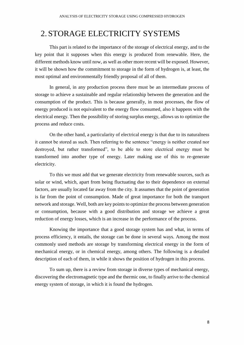
electricity is demanded, and the price is high, we will move the water downstream
towards the turbine to generate electricity. In contrast, at night, during the valley hours
(those in which electricity is not demanded and the price is lower) we will pump the water
into the upper tank, recovering in that way the potential energy of the water, to continue
the next day with the same process [1].
Figure 1.Hydroeletric scheme during the day.
The pumping installation can be developed in different ways, but the most used
are the ternary group or the binary group. In both, an electric motor is used that will be
used as a generator or motor depending on what is needed, but the difference between
each way of installation is found in the pumping system. In the ternary group there is a
pump and a separate turbine, both in connection with the electric machine. And instead,
in the binary system there is only one turbine that is used as pump and turbine. These
turbines are usually, because of its configuration, Francis turbines.
Hydraulic dams are a type of installation capable of storing a large amount of
energy, because of the extent of the dam can be very large. Therefore, this also leads to
disadvantages with the construction, like the high level of descent that is required between
the upper and lower levels, as well as the time it takes to build it, and the environmental
impact that is associated. On the other hand, apart from the initial investment that
construction implies, we also have to obtain electric power, determined by the turbine,
then it is not a direct transformation between potential and electric, since it is conditioned
in time by the step of the turbine.
Even though, despite the inconveniences that it presents with reference to its
geographical limitations, the limitations imposed by the start and stop times, and the
limitations of operation of the turbines. Hydraulic power stations today are a viable and
proven solution for the storage of large amounts of energy. Also, as the air compression
ANALYSIS OF ELECTRICITY STORAGE USING COMPRESSED HYDROGEN
11
centers, which we will detail later, its maturity and the great advance in its technologies,
as well as its flexibility and ease of adapting to the needs of the demand, allow an optimal
storage at same time that they facilitate a balance in the electrical distribution system.
2.1.2. Kinetic energy
One of the mechanisms that can be used to store energy in the form of kinetic
energy are the inertia steering wheels. These devices concentrate the energy in a rotor to
later use the stored kinetic energy to transform it, through a generator, into electrical
energy.
A difference regarding the form of potential energy storage, is that in this type of
storage based in mechanical energy it has already associated losses that are due to the
inertia steering wheel. Losses that can amount to about 20% of the total stored energy [2].
That is why from its origins in the nineteenth century, the improvement studies, especially
in the part of science of materials, have focused on the constitution of new rotors of
different materials that reduce that losses.
It is known that the fundamental element of this type of storage is the rotor, and
essentially its moment of inertia that will be the one that later is used to turn the axis of
the generator. That is why the geometry of these is a key point in the design, at the same
time as the materials used in construction.
The operation is very simple, the electrical energy produced turns an electric
motor that simultaneously rotates a rotor where kinetic energy is stored. Later, when
electric power is demanded, the rotor rotates in the reverse direction generating new
electricity to the electric motor, which now acts as a generator.
However, the electric energy recovery system is much faster and more immediate
than that of potential energy, as this rapidly stored kinetic energy is transformed into
electrical energy through the transformer connected to the axle of the steering wheel.
Regarding the storage capacity, it depends mainly on the deformation point of the rotor
of the steering wheel, providing this a wide variety of resistance of rotors and storage
capacity in the market. At present, a type of rotor has been developed, the so-called super
flywheels, which contain a high energy density while minimizing friction losses due to
improvements in their materials.
Inertia steering wheels can be divided into two types: low speed metal rotor
systems (5.000 rpm) and high-speed metal components (10.000-50.000 rpm). The former
is commonly used for short or medium-term energy storage, while the second ones are
the majority in the process of development focusing on the storage of higher amounts.

ANALYSIS OF ELECTRICITY STORAGE USING COMPRESSED HYDROGEN
12
This type of storage centered on the motor pair of the inertia steering wheel, as an
energy vector, is a system used throughout history and for different utilities. However,
today, due to its rapid response it can ensure the necessary energy input in a short interval
of time, it can be found as a complement to the regulation of the distribution electricity
system. Then when they deal with systems with renewable energy sources such as wind
farms or photovoltaics, inertia steering wheels serve to cover the “peaks” of demand. The
same case is to support batteries, in the case of the starter, providing a more continuous
supply of energy.
All this added to its little maintenance required and that it is a totally clean energy
form, position the inertia steering wheels as good energy regulators working in parallel
with other storage systems.
2.1.3. Compression energy
In this method of storage of electrical energy by compression, we will focus on
the compression of a gas, specifically air. From the acronyms CAES (Compressed Air
Energy Storage) is born the technology that starts with electrical energy in hours of low
demand to drive a compressor and store the compressed air in tanks and appropriate
deposits. In other words, cheap electric power is transformed into a potential energy of
pressurized air and stored in this way.
Subsequently, the operation of the post-generation of electricity goes through an
expansion of compressed air to a turbine, which will rotate the axis of the generator
producing electric power.
For the initial stage of expansion, it is needed to reheat the air before entering the
turbine. This fact, coupled with the fact that there is a process of energy release in the
form of heat, causes two types of compression systems, the diabatic system and the
adiabatic system to open.
The first one is implemented so far, although with few installed plants that are still
in operation, however, the adiabatic variant is the future bet to be able to use the heat
released in the compression of the air to subsequently reheat it before the expansion in
the turbine. This would significantly increase the energy efficiency of the process.
Apart from these two, we also find other versions such as the submarine or the
isothermal that open new alternatives still in research and prototype.
The great variety that presents regard to amount of storage the technology CAES,
opens the door to a wide range of applications. At least, among them we emphasize the
ANALYSIS OF ELECTRICITY STORAGE USING COMPRESSED HYDROGEN
13
marine wind. Helping this in the balance between generation and demand through
submarine air compressed tanks. Although, despite its high degree of maturity, there is
not much the number of large-scale installations.
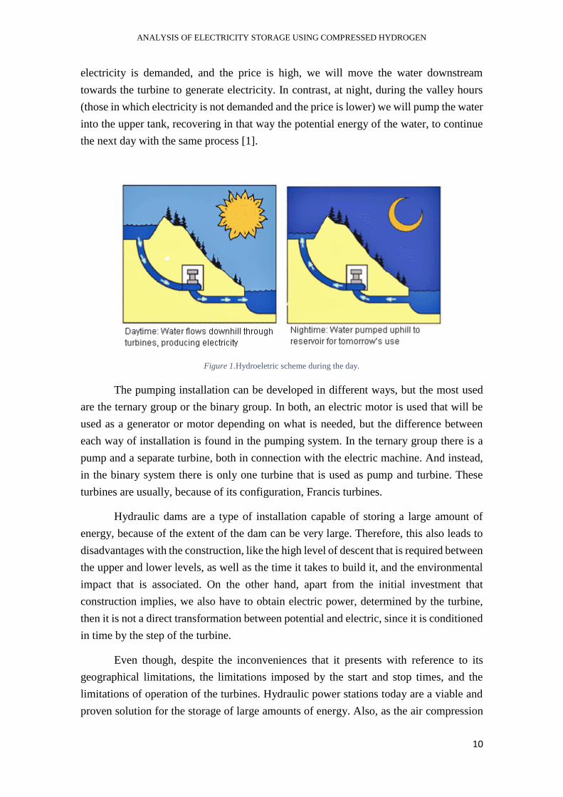
However, it is a future route especially for renewable stations where water
pumping may not be possible, such as wind farms or photovoltaic parks [3].
Figure 2. Compression storage scheme
The image could show an infrastructure of this type of storage, which is used the
electrical energy generated by the wind for then by a compressor storage the air in tanks
under the sea.
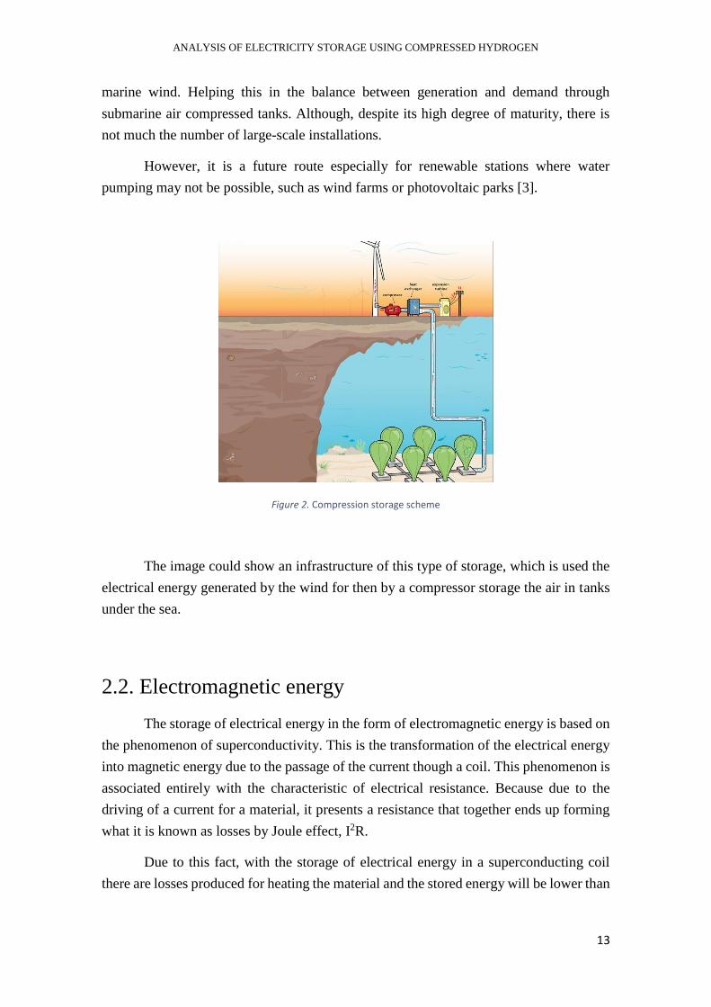
2.2. Electromagnetic energy
The storage of electrical energy in the form of electromagnetic energy is based on
the phenomenon of superconductivity. This is the transformation of the electrical energy
into magnetic energy due to the passage of the current though a coil. This phenomenon is
associated entirely with the characteristic of electrical resistance. Because due to the
driving of a current for a material, it presents a resistance that together ends up forming
what it is known as losses by Joule effect, I2R.
Due to this fact, with the storage of electrical energy in a superconducting coil
there are losses produced for heating the material and the stored energy will be lower than
ANALYSIS OF ELECTRICITY STORAGE USING COMPRESSED HYDROGEN
14
the initially supplied. Then this problem is a challenge to solve to make electromagnetic
storage efficient.
Because the resistance that appears to the material is linked to the temperature,
one of the solutions is to lower the temperature until the electrical resistance of the
material is practically zero. The temperature which makes happen that is called critical
temperature of superconductivity and is an integral property that has the superconducting
materials to act without electrical resistance.
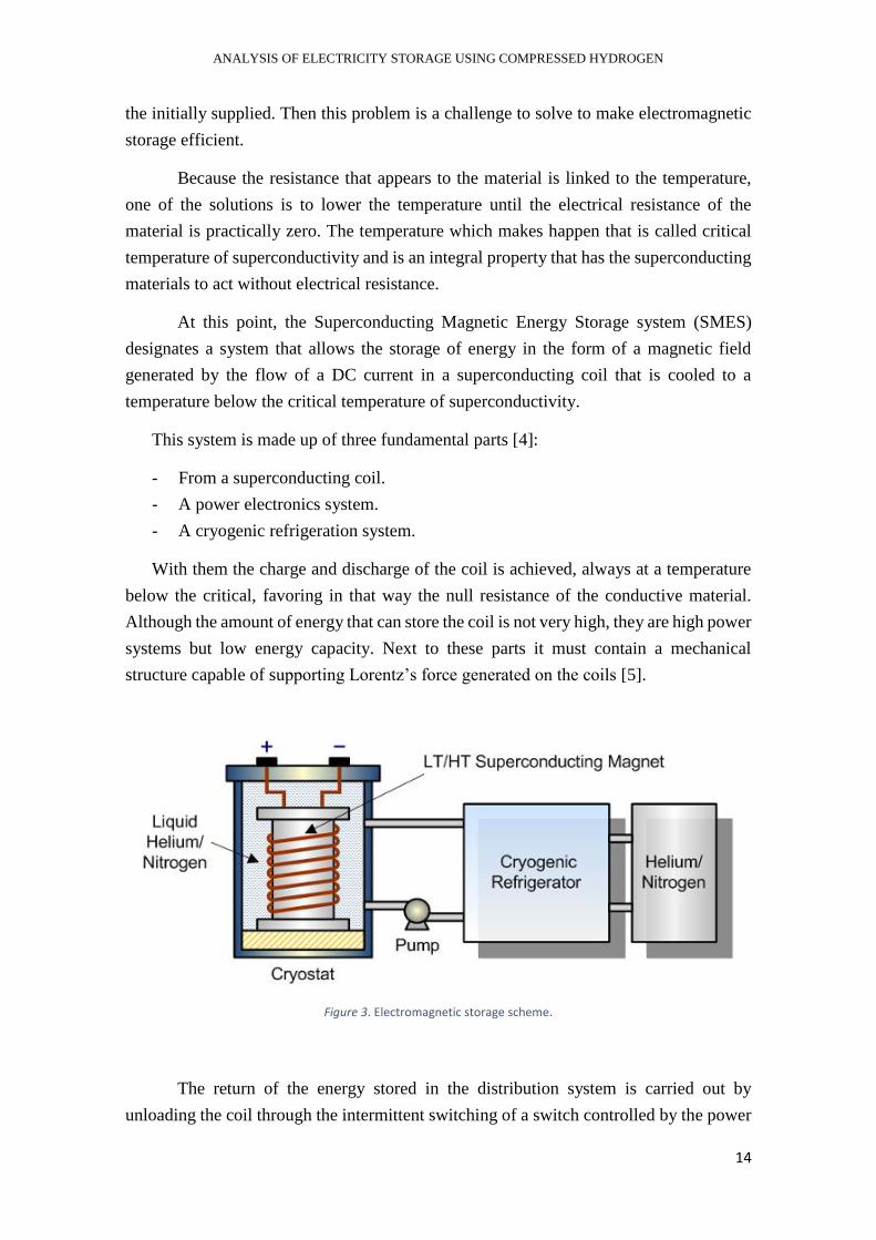
At this point, the Superconducting Magnetic Energy Storage system (SMES)
designates a system that allows the storage of energy in the form of a magnetic field
generated by the flow of a DC current in a superconducting coil that is cooled to a
temperature below the critical temperature of superconductivity.
This system is made up of three fundamental parts [4]:
- From a superconducting coil.
- A power electronics system.
- A cryogenic refrigeration system.
With them the charge and discharge of the coil is achieved, always at a temperature
below the critical, favoring in that way the null resistance of the conductive material.
Although the amount of energy that can store the coil is not very high, they are high power
systems but low energy capacity. Next to these parts it must contain a mechanical
structure capable of supporting Lorentz’s force generated on the coils [5].
Figure 3. Electromagnetic storage scheme.
The return of the energy stored in the distribution system is carried out by
unloading the coil through the intermittent switching of a switch controlled by the power

ANALYSIS OF ELECTRICITY STORAGE USING COMPRESSED HYDROGEN
15
electronics system. The discharge is made to a capacitor that provides a continuous
voltage input to an inverter that finally delivers the voltage required by the AC network.
Among the advantages of this system is its rapid response time, which adapts them
notably to any type of auxiliary storage service, especially to ensure the quality of the
distribution system. That is because it alone has not enough capacity to configure a
complete storage system, it is always associated with other type forming a hybrid system.
This system and the inertia steering wheel are competing in the auxiliary systems
market. However, although it provides greater reliability and security since there is no
mobile part, it is true that the disadvantage of having a cryogenic temperature system
makes a hard competition between both to choose which is better.
2.3. Thermal energy
In many of the processes of generation of electrical energy, the heat, or rather the
energy in form of heat, the thermal energy plays a fundamental role in all of them. In
photovoltaic farms, in cogeneration plants or in thermal power stations, as its name
suggests, heat is the one that develops the main role.
In all of them, what it is looking for is to use this thermal energy to heat a fluid
that later with its expansion in a turbine move the axis that drives the engine generating
electricity.
Although the thermal energy is present in most of the processes of electrical
generation and other forms of energy, the inverse process of transformation of thermal
energy from any other, usually is not the most efficient way. Then for that the thermal
energy is stored directly when it is produced.
That is why, instead of storing the electrical energy by transforming to another
type of energy as in the cases seen before, now we go a step back and store directly the
thermal one that later we will use in the production of electrical energy.
This type of storage is present in the solar thermal systems, concentrated solar
power plants, in microturbines, but at least one of its most widely used applications is to
take advantage of the residual thermal energy sources and increase the performance of
the thermal processes. This phase where the residual heat is used to reheat the gas of the
cycle is more well-known like regeneration of the systems in gas turbine and steam
turbine. Fact that positions the accumulation of thermal energy as a precise complement
to increase the efficiency of these processes.
ANALYSIS OF ELECTRICITY STORAGE USING COMPRESSED HYDROGEN
16
Regardless of the origin of thermal energy, the purpose of these TES (Thermal Energy
Storage) systems offers great advantages for the management of transport and distribution
of energy. As is the case with [6]:
- Increased efficiency in many processes by allowing the recovery of residual heat.
- Absorption of consumption peaks and decreased dimensioning of generation
systems.
- Reduction of the temporary deviations between the generation and consumption
profiles.
- The use of renewable energy sources is facilitated.
Within the systems of thermal energy accumulation, they can be classified according
to different criteria. Among them the classifications according to the period of
accumulation can be emphasized, according to accumulated temperature and according
to the basic principle of accumulation. The latter is the most common one and is divided
into three major groups: sensitive accumulation, latent accumulation and thermochemical
accumulation.
Sensitive accumulation is based on the energy capacity of the materials to store
thermal energy by heating them with a good insulation system. Then the accumulation of
energy will have a direct relation with the material and its properties, as well as of the
insulating material used.
On the other hand, the latent accumulation is based, as it says the name, in the latent
heat. This is the energy needed to produce a phase change in a given material. This type
of storage allows us to accumulate more energy than sensitive accumulation.
And finally, there is the thermochemical accumulation focused on the release of heat
from chemical reactions. Storage occurs with endothermic reactions, and then we release
it with exothermic. Within this group there are authors who call them reactions that have
to do with the hydration and dehydration of absorption and adsorption.
As one of the most common uses has been mentioned, it is the use of the residual heat
of industrial processes with thermal demands, but at least the important role played by
thermal systems in renewable sources is worth noting. And it is that it allows us to balance
the demand between generation and consumption, before using this heat for electric
generation, as in the case of solar farms.
ANALYSIS OF ELECTRICITY STORAGE USING COMPRESSED HYDROGEN
17
2.4. Chemical energy
Technologies based on chemical energy center their foundation in link energy that
contains a molecule. When a chemical reaction takes place, it is this binding energy that
is used to form new compounds, either by breaking them or by forming more. Fact that
will make the energy balance be based on the binding energy of the molecules.
Within this type of energy storage, we can classify into two large groups. The
storage based on electrochemical systems, that is, those based on the exchange of
electrons between substances, being this passage of electrons the cause of the storage or
release of energy. And on the other hand, the storage based on the combustion and
oxidation reactions, with which the compound, together with oxygen and an external
input, achieves a great energy release in its combustion.
Both types of storage are well-known and used, about the electrochemical system
is the operating principle of the batteries. Since the transformation of chemical energy
into thermal energy through combustion is not the most efficient, electrochemical systems
focus on oxidation-reduction reactions, also known by the REDOX nickname. Within the
great field that supply the batteries, we find different types and uses, which will be
exposed in more detail later.
In the systems based on the combustion reactions, we can emphasize the use of
hydrocarbons and petroleum derivates. With this, apart from being a fluid of easy
distribution and storage, it has a great energy in its links. Then, despite its environmental
impact, its high energy density positions it in one of the most commonly used systems
today. Although, new sources such as hydrogen advance firmly gaining importance in
this field and position itself as the new alternative.
In this part, we will develop both systems based on chemical energy, the
electrochemical and the combustion system. Then, we will see how the role of hydrogen
is gaining more prominence because its combustion does not emit any harmful gas, fact
that positions hydrocarbons as a low resource recommended from the environmental
point of view. That is why the electricity produced will be used to generated hydrogen by
electrolysis for then use it in a combustion reaction to release the link energy that contain
its molecules.
2.4.1. Chemical combustion energy
In this case, instead of using the electron flow between the element as the main
operation to generate and store electricity, the systems focus on the binding energy of the

ANALYSIS OF ELECTRICITY STORAGE USING COMPRESSED HYDROGEN
18
molecules, and specifically on the formation and breakage of electrons, these links. It will
be then, in the derogatory and exergonic reactions in which the study will be determined.
Since the emergence and modernization of combustion engines as we know them,
fuel has been the hydrocarbons and petroleum derivatives, and it is that they are treated
with fluids with a high energy density and that allow easy transport and exploitation of
the resource. Then, much of the energy landscape revolves around this type of energy,
and specifically in the combustion reaction of these compounds.
However, the increase in the problems related to pollution and the environmental
impact have made the decrease of using this energy system and look for other more
respectful alternatives.
In this case, another element with a great connection energy is hydrogen. That is
why even at the start of the study, this is being considered as an element of storage and
subsequent use for the generation of electricity in fuel cells.
In this way, an electrical cycle is generated around the hydrogen, starting from the
generation of this one from electrolysis by means of the electrical energy produced to the
renewable ones, a later storage in tanks of the hydrogen, for finally end up using this in a
combustion. The good point is that it does not produce any greenhouse gas, that positions
it as a better fuel than hydrocarbons.
However, from the energetic point of view the efficiency of this process is not as
good as if the hydrogen is used in a fuel cell. So, as it will be shown after in the
electrochemical part, after having the production and the storage of the hydrogen, it will
be reused in a fuel cell producing electricity again. That device is an electrochemical
device which is focused in the flow of the electrons to produce electricity instead on
broking the links between the molecules.
This kind of device, between the association of an electrolysis before to produce
the hydrogen is the one that plays an important role in the future. And this specific part
of production and storage hydrogen will be the aim of the study as it will be shown in the
following parts. Otherwise, how it works will be introduced in the part of electrochemical
energy for then in the third chapter found the large discussion about it.
2.4.2. Electrochemical energy
That systems that use the electrochemical energy as a method of storage, as
already stated before, are the batteries. These are based on the processes of oxidation and
reduction of a component, which either releases or captures electrons, making this

ANALYSIS OF ELECTRICITY STORAGE USING COMPRESSED HYDROGEN
19
exchange the principle of operation both to store electricity and to release it in the opposite
process.
The reduction process is essentially the reaction in which an element “captures”
electrons, this occurs in the part that is known as a cathode. On the other hand, an
oxidation is the opposite process, that is, the reaction in which the element, located at the
anode, “releases” an electron. Both reactions, if carried out at the same time and in the
same environment, which give rise to the formation of a flow of electron circulation
between the anode and the cathode. Using the electron that is released in one, to capture
it on the other side, and consequently generating a voltage due to its flow.
This electron exchange is the chemical principle used by batteries both to store
electrical energy inside it, and subsequently to supply it. To store it, we will use the
external electrical voltage to charge the battery, and later with the passage of electrons
from the anode to the cathode we can recover this electrical energy.
Functionally, the battery can be defined as a set of cells, where each would have
two parts that would be the two electrodes, that is, the anode and the cathode, connected
by an acid medium, which we call electrolyte. The flow of electrons between cells
represents the current density of the battery (A/cm2). Apart from the current, each type of
cell has an associated work voltage (V), which is conditioned by the potential difference
between the initial and final electrons.
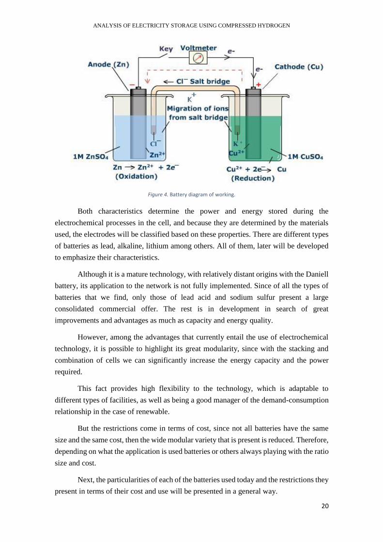
In a general way the elements of a cell could be classified like:
- Anode electrode
- Cathode electrode
- Electrolyte, conductive medium of electrons
- Insulating membrane between electrodes
- Two electrochemical pairs to participate in semi reactions
- Container that conforms the cell
We can exemplify it with this characteristic image for a Zn-Cu electrode in
dissolution [7].
ANALYSIS OF ELECTRICITY STORAGE USING COMPRESSED HYDROGEN
20
Figure 4. Battery diagram of working.
Both characteristics determine the power and energy stored during the
electrochemical processes in the cell, and because they are determined by the materials
used, the electrodes will be classified based on these properties. There are different types
of batteries as lead, alkaline, lithium among others. All of them, later will be developed
to emphasize their characteristics.
Although it is a mature technology, with relatively distant origins with the Daniell
battery, its application to the network is not fully implemented. Since of all the types of
batteries that we find, only those of lead acid and sodium sulfur present a large
consolidated commercial offer. The rest is in development in search of great
improvements and advantages as much as capacity and energy quality.
However, among the advantages that currently entail the use of electrochemical
technology, it is possible to highlight its great modularity, since with the stacking and
combination of cells we can significantly increase the energy capacity and the power
required.
This fact provides high flexibility to the technology, which is adaptable to
different types of facilities, as well as being a good manager of the demand-consumption
relationship in the case of renewable.
But the restrictions come in terms of cost, since not all batteries have the same
size and the same cost, then the wide modular variety that is present is reduced. Therefore,
depending on what the application is used batteries or others always playing with the ratio
size and cost.
Next, the particularities of each of the batteries used today and the restrictions they
present in terms of their cost and use will be presented in a general way.

ANALYSIS OF ELECTRICITY STORAGE USING COMPRESSED HYDROGEN
21
2.4.2.1. Lead-acid batteries
This type of battery is one of the most widespread in the automotive world due to
its reduced cost and to its application used to load the auxiliary services of the car such
as the starter, the lights or the internal radio.
It is a simplified structure because the same lead is used in anode and cathode because
it can act as for the oxidation and reduction. The reactions that take place are:
Oxidation: PbSO4(s) + 2e- <-> Pb(s) + SO42-(aq)-0.356V
Reduction: Pb4+(aq) + 2e- <-> Pb2+(aq) +1.685V
Global reaction: Pb + PbO2 + 2H2SO4 <-> 2 PbSO4 + 2 H2O (E=2.041 V)
Although they have a low energy density and a high weight, as already stated, are the
most commonly used batteries in automobiles, furthermore they are also present in
communications stations, in substations or in emergencies, and in industrial plants. Since
we can emphasize that as the main function of lead acid batteries, they provide an energy
reserve to compensate for any error in a plant or sporadic action. However, since they
only provide a few minutes of energy they are also used as starter batteries for motors.
Despite of the limitations of both the energy density, the long load times and the
excessive maintenance they need, their low cost and their technological maturity make
them still competent batteries in the market of the environment discussed above.
2.4.2.2. Batteries with alkaline electrolyte
These types of batteries are the most commonly used after lead-acids, but unlike
the lead ones, they use an alkaline medium to ensure the electron flow between anode and
cathode. This acid medium is what we call electrolyte.
Depending on what the electrodes are, we differentiate different variants:
- Nickel-Cadmium (Ni-Cd)
- Nickel-Zinc (Ni-Zn)
- Nickel-Iron (Ni-Fe)
- Nickel-Metallic hydrides (Ni-MH)
All of them located within an acid solution that allows and facilitates the exchange of
electrons between the two.

ANALYSIS OF ELECTRICITY STORAGE USING COMPRESSED HYDROGEN
22
After the appearance of lead acid batteries, the following batteries that appeared on
the market were those of nickel-cadmium, which is currently the most used rechargeable
battery in the market. Like lead ones, they also present a wide variety of modularities and
sizes, but these are of higher cost, besides adding the problems that cadmium and nickel
present to the environment. That is why it becomes an uncertain future for this type of
battery.
Among the applications where these types of batteries are found, we can emphasize
the use of railroads, aircraft, traction batteries for locomotives and industrial vehicles.
Although, due to its polluting character and the advantages in the technology area,
these batteries are slowly being replaced by ion-lithium batteries, which will be discussed
below.
2.4.2.3. Lithium ion batteries
As its name suggests, these batteries are based on lithium, a very light metal
material (Pm = 6.939 g/mol) while having a very high standard of reduction potential.
These characteristics position it as an optimal material for use as an electrode in
electrochemical batteries.
Although the reduction of lithium ion to metallic lithium causes dendritic growth
in the grain of the material, which can lead to short circuits in the battery. What ion-
lithium batteries do is to eliminate a metal lithium electrode and replace it with an
electrode that intertwines or inserts the lithium into crystalline network of the material
used as an electrode.
These new concepts of electrochemical reactions of insertion and collation
position ion batteries in the focus of the investigation, as well as one of the most promising
technologies for the future.
Due to its recent appearance, many materials are found in research for both anode,
cathode and electrolyte. However, in all of them what is sought is the maximum efficiency
in the interleaving/ de-interleaving of the lithium and minimizing the degradation caused
by these processes. Among the newest and most notable materials are graphite, and coal
derivates such as graphene or active carbon for the anode.
This type of battery as it is said before, is ending with alkaline batteries. In fact,
in small applications like batteries of mobile phones or computers all are of this type. And
little by little, due to its low weight and low volume, its high energy density and degree
of maturity will take over other technological areas, while reducing its costs little by little.

ANALYSIS OF ELECTRICITY STORAGE USING COMPRESSED HYDROGEN
23
2.4.2.4. Hydrogen in an electrochemical device
As it was talked before, to have the maximum efficiency with the hydrogen, it
must be used in a fuel cell instead of in a combustion engine. Here it will be introduced
the part of the production, the electrolysis, and then “the invers part” the process in the
fuel cell. Both focused in the flow of the electrons between the hydrogen.
The electrolysis process can be carried out with different methods as after will be
exposed, but mainly the function lies in using electricity and water to generate hydrogen.
Starting from for example the electricity produced in a wind farm, it will be used to break
the water H2 bonds, to separate the hydrogen and oxygen molecules.
Once obtained this hydrogen, it will be stored in the most optimal way, finally, in
the moment necessary to be able to return to generate electricity. This step of hydrogen
to electricity will be realized through a fuel cell. That part is the one that allows the
generation of electricity from hydrogen achieving the maximum efficiency.
The most important point in all this process surrounding the hydrogen is its high
energetic density, that in all these storage forms is bigger than the energetic density of the
other methods that are exposed before. As it is showed in the picture [8]:
Figure 5.. Energy density of Fuel

ANALYSIS OF ELECTRICITY STORAGE USING COMPRESSED HYDROGEN
24
In addition, it is used to balance the production-consumption relationship of
renewable sources, and the high energy density that owns the hydrogen bond, the thing
that positions it as a viable and respectful alternative is that its combustion only generates
water vapor as a product. This environmental point in front of the greenhouse gas of the
combustion of hydrocarbons positions hydrogen as the fuel of the future.
On the following chapter, all related to the hydrogen molecule will be exposed.
And will be also showed how the electrolysis works and the different types of. Otherwise,
things like the system of hydrogen’s storage and how we can reuse it in a cell fuel are
also in this following part.
ANALYSIS OF ELECTRICITY STORAGE USING COMPRESSED HYDROGEN
25
3. HYDROGEN AND ELECTROLYZER
After the exhibition of the different types of storage in which the electricity
produced from renewable energy can be transformed. Now, as it had already been
introduced at the beginning of this work, the study is focused on hydrogen as the energy
alterative of the future.
This following section starts with the study from the origin of the molecule, to
know in detail what is hydrogen, and which are its chemical characteristics. In previous
sections, some of the characteristics of this element have also been introduced, such as its
high energy power and the little environmental impact of its combustion. However, all
these particularities that provide hydrogen with such great importance will be explained
in depth.
Once the element is known, the description of the different processes with which
hydrogen can be obtained will continue. And particularly with the method of production
that will be used in this study: electrolysis. This process will be explained in detail, while
it will show why it is important in the use of renewable. By performing a comparison
between different types of electrolysis we will go through this process until we find the
type of electrolysis that will later be used by us in our work.
As it is known, every production system has a part of storage, then the different
types of known hydrogen transport and storage systems will also be exposed. At the same
time, we will see what will be the most optimal for the case that is related with our study.
Until here, it would be referring to our case of study that will then be developed.
That, as has already been stated before, it is none other than the production of hydrogen
from renewable and the most optimal storage for a quick retrieval. The point that was
dealt with was more detailed in the following section of the stationary model chosen.
Although it is not part of the modeling of the study of this work, also the systems
with which we can regain electricity from hydrogen, will be explained, here it is the fuel
cells. At the same time, the text will talk about the economic study and the impact that
this technology could have on the current energy system. Always with a vision of the
future, towards a more sustainable and environmentally friendly energy landscape.
ANALYSIS OF ELECTRICITY STORAGE USING COMPRESSED HYDROGEN
26
3.1. HYDROGEN, THE ELEMENT
Hydrogen is a chemical element represented in the periodic table with the symbol
H and with an atomic number of 1. When it is in normal conditions of pressure and
temperature, it is in the form of diatomic gas (H2) without color, flavor and smell
characteristics, as well as being a highly flammable non-metal.
Its properties make it the lighter chemical element with an atomic mass of 1.00794
[9] as well as being the most abundant in the universe, reaching 75% of the visible
material.
Although in the universe it is so present, and more to the stars, which are mostly
composed of hydrogen in the plasma state, on Earth the situation is different. Here,
hydrogen as an element very scarce, then we only obtain it through forced production at
the place and moment in which is needed. As is the case with the processes of electrolysis
of water or obtaining from natural gas.
The lack of the hydrogen element as such is due to its small mass, which allows it
to escape from earth gravity easier than other heavier gases. But, because of its association
characteristics, it is present along with other elements in different compounds. Most of
the hydrogen is present in H2O water and hydrocarbon chains, completing the H3C-H2C-
CH… carbon links. But specifically, the CH4 methane is the gas in the process to obtain
more simple hydrogen. Then it will be from the methane where the processes of obtaining
are mainly rotated.
Hydrogen as mentioned above can be found in different ways, but in a natural way
it has three isotopes: protium, deuterium and tritium (1H, 2H, 3H) of which only
deuterium is the stable isotope of the hydrogen.
3.2. THE CYCLE OF HYDROGEN
Until this part, it is known which the importance of hydrogen is and why is one of
the main alternatives to the future as an energetic vector. But, which is his cycle of
production, storage and reconversion to electricity? That is what will be exposed.
The full process of storage electricity by electrochemical way using hydrogen it
can be divide in three main parts: the dissociation or reduction of molecules, the storage
of the molecule and the final process of reconversion in electric energy.
ANALYSIS OF ELECTRICITY STORAGE USING COMPRESSED HYDROGEN
27
The first one, is also known as electrolysis or “electrolysis of water”. As its name
represents the process is focused in the dissociation of the molecule of H2O using
electrons to break the links of the molecule. The flux of electrons is produced by the
electric energy generated in renewables, for example in photovoltaics (PV) or by wind
power.
2 H2O <-> 2 H2 + O2
After the obtention of hydrogen by the electrolysis, the molecules should be
storage in an optimal way to facilitate the transport and the posterior reuse. There are to
many forms, but the mainly used are by compression reaching high pressure level in a
different phase liquid or vapor, or in absorption by metals, known also as metal hydrides.
And finally, to equilibrate the equation production-consume in renewables we
need to reconvert our energy storage in new electrical energy or other combustibles.
Using the H2 directly in a Fuel Cell to produce electricity, or in a synthesis process
forming methane or new hydrocarbons fuel in a Fischer-Tropsch process.
All of three parts will be exposed, focusing with special attention the first part of
electrolysis because it is where the object of the thesis resides.
3.2.1. Electrolysis of water
In this work, as it is said before, the production of hydrogen is going to be formed
from the process of water electrolysis. Apart from the simplicity of the reaction to create
hydrogen, then it is one of the most environmental friendly combustible that can be used
because its combustion has as a residue just vapor of water.
The process of dissociation of water has place in an electrolytic cell, a mechanism
similar as a fuel cell but with the opposite mode of working. Instead of producing
electricity due to the electron pass between the reactions in the cathode and anode, now
this current of electrons is introduced in the electrolytic cell to do the invers reactions
producing in that way H2 and O2.
The electrolyzer or the cell electrolytic is formed by two conductors called
electrodes and an acid solution known by the name or electrolyte. Related to the
electrodes must be different properties that makes a good process, these are being
resisting to corrosion, having a good conductivity, having an integral structure and
achieving adequate catalytic properties.
The electrodes are separated by a membrane, and the type of membrane and the
type of electrolyte are who decided the type of electrolyzer that is used. The most common
ANALYSIS OF ELECTRICITY STORAGE USING COMPRESSED HYDROGEN
28
are the alkaline electrolyzer and the PEM electrolyzer, as well as the electrolyzer of high
temperature as the MCFC or SOFC.
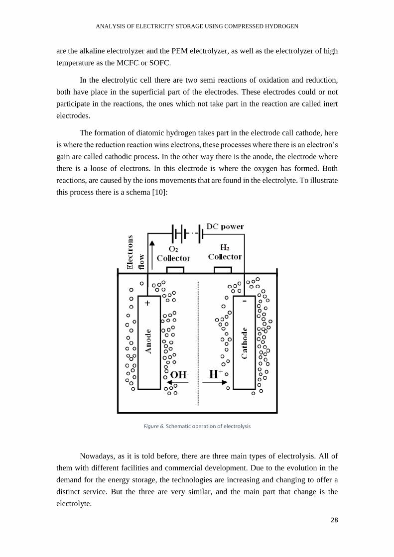
In the electrolytic cell there are two semi reactions of oxidation and reduction,
both have place in the superficial part of the electrodes. These electrodes could or not
participate in the reactions, the ones which not take part in the reaction are called inert
electrodes.
The formation of diatomic hydrogen takes part in the electrode call cathode, here
is where the reduction reaction wins electrons, these processes where there is an electron’s
gain are called cathodic process. In the other way there is the anode, the electrode where
there is a loose of electrons. In this electrode is where the oxygen has formed. Both
reactions, are caused by the ions movements that are found in the electrolyte. To illustrate
this process there is a schema [10]:
Figure 6. Schematic operation of electrolysis
Nowadays, as it is told before, there are three main types of electrolysis. All of
them with different facilities and commercial development. Due to the evolution in the
demand for the energy storage, the technologies are increasing and changing to offer a
distinct service. But the three are very similar, and the main part that change is the
electrolyte.
ANALYSIS OF ELECTRICITY STORAGE USING COMPRESSED HYDROGEN
29
As a part of the thesis it is going to be exposed the three types of electrolyzer and
having an intensive description about the alkaline electrolyzer and de PEM electrolyzer
because this last one is the one that will be modeled after. One of the reasons to choose
this one is related to the high purity of the hydrogen that produces, despite its young
majority, and because it is the one that mostly use in small renewable plants as solar
panels or wind farms. In this type of electrolyzer the H2 has a purity round 99,8% de water
in volume, but in some cases after having the electrolysis it is common to reconduct the
hydrogen flux to a device where it can be more purified. The rest is oxygen and water
vapor.
3.2.1.1. Alkaline electrolyzer
As his name says, an alkaline electrolyzer is an electrolytic cell where the
reactions of reduction and oxidation to form hydrogen have place in an alkaline solution.
These reactions are not spontaneous, that is why it is need the electric current provide by
the renewables to be able to form the hydrogen.
In the part of the electrodes, the most common is having a cathode formed by still
or an alloy still-Ni, apart than having in addition some catalyzers to improve and increase
the reaction’s part of the electrode. Otherwise, for the anode is common to use nickel or
a nickel’s recovering, apart from other cobalt or metallic anode, that are also
commercialized.
But, most of the importance resides in the electrolyte part. The alkaline solution
is the responsible to provide the ions for conduction in the interior of the electrolytic cell.
One of the advantages of using an alkaline solution in opposition to an acid solution, is
that in the alkaline one the impact to the corrosion is less than in the acid one, so the
electrode could operate in a better way. The solution commonly used is based in KOH.
These types of alkaline solutions increase their conductivity by the way that the
temperature of working also increase. That is why usually the operation point is round
60º and 90º centigrade, temperature near the evaporation point of the solution.
The electrolyte is the element that connect the two electrodes in the cell, but there
is another element called membrane that is the responsible that between electrodes just
take part the flux of ions. In this case the membrane is used to be formed by a ceramic
material.
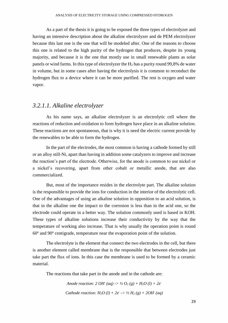
The reactions that take part in the anode and in the cathode are:
Anode reaction: 2 OH- (aq) -> ½ O2 (g) + H2O (l) + 2e-
Cathode reaction: H2O (l) + 2e- -> ½ H2 (g) + 2OH- (aq)
ANALYSIS OF ELECTRICITY STORAGE USING COMPRESSED HYDROGEN
30
These reactions are forced by the pass of ions of (OH-) and potassium (K+) that are in the
dissolved in the alkaline solution and are these ones the ions which pass through the
diaphragm generating the flux of electrons. After that, the electrons when arrive to the
cathode are combined with the molecule of water broking them in hydrogen and hydroxyl
ion, the last ones are those who come back to the anode caused by the action of the electric
camp.
This kind of electrolyzer are the most used for the big production of hydrogen,
reaching an efficiency round of eighteen percent, despite the normal range is round 60%.
This advantage is one of the most important, because could suppose a real alternative in
a future, making the renewables as a good alternative in the energetic system.
3.2.1.2. PEM Electrolyzer
These second type of electrolytic cells, as it is told before, the thing that basically
changes from the alkaline one is the electrolyte. In this case, the electrolyte is solid, and
it is known as a Proton Exchange Membrane (PEM). In front of the liquid solution that
facilitated the ion flux in the alkaline one, here there is a polymeric membrane.
The operation mode is also based in the flux of electrons, but in this case, the
protons are the ones which are in the flux through the membrane and the electrons have
an extern current. As in the alkaline electrolyzer the hydrogen is produced in the cathode,
and the anode is the rest production of oxygen.
This kind of technology is in a huge development these days, and it is hope that
the efficiency of PEM electrolyzer reach high levels. Between his advantages, it is found
the point that cause its polymeric membrane, it is not the dependence of a liquid solution.
That is why the problem of corrosion is avoid. Apart from that, it is also some advantages
as its good chemical and mechanic stability, a good proton’s conductivity and a high
impermeability of the gas.
Other difference from the alkaline ones is the amount of energy available to
produce. These are focused, due to its low technological maturity, to some small plants
of production. But, despite the fact, there are also a promising alternative for the future.
Due to the fact of this small capacity of production, there are alternatives for the
electricity produced by the photovoltaic solar panels (PV), and other systems of small
plants renewables.
ANALYSIS OF ELECTRICITY STORAGE USING COMPRESSED HYDROGEN
31
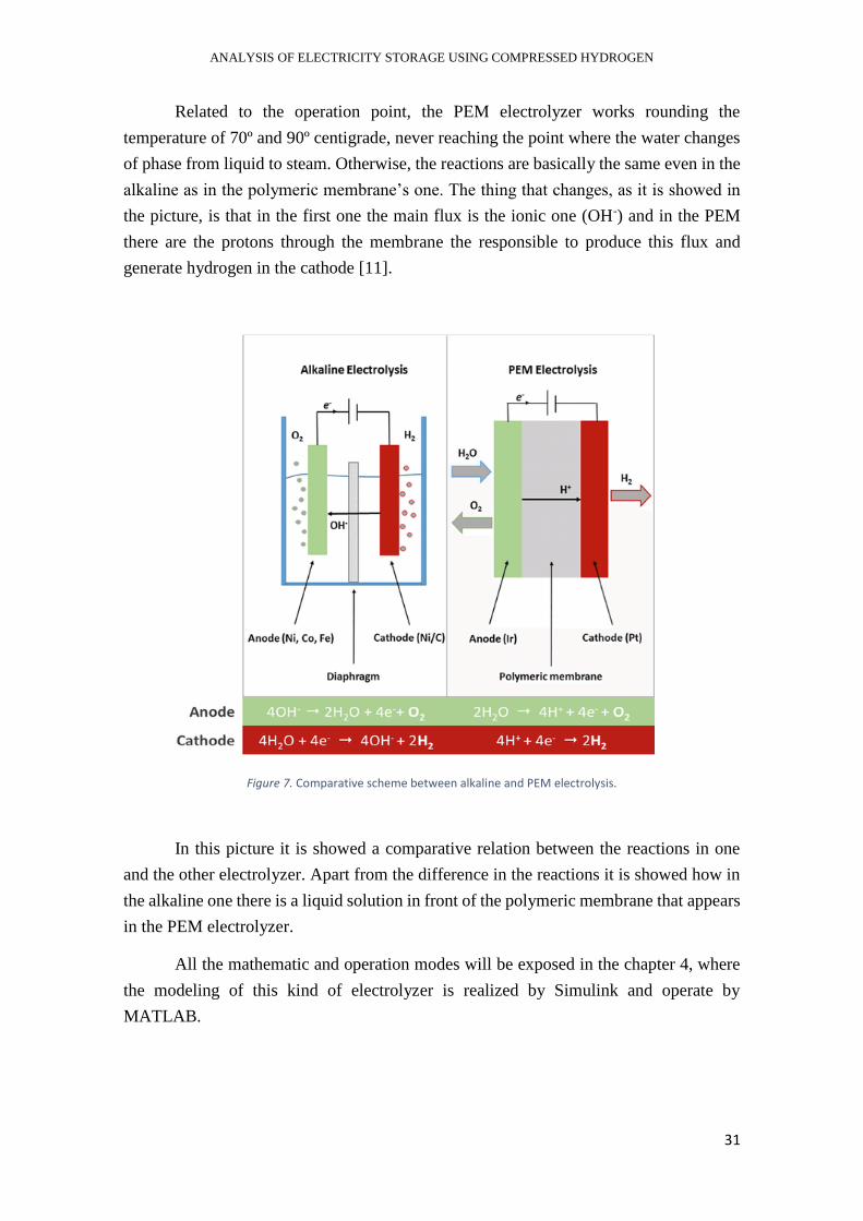
Related to the operation point, the PEM electrolyzer works rounding the
temperature of 70º and 90º centigrade, never reaching the point where the water changes
of phase from liquid to steam. Otherwise, the reactions are basically the same even in the
alkaline as in the polymeric membrane’s one. The thing that changes, as it is showed in
the picture, is that in the first one the main flux is the ionic one (OH-) and in the PEM
there are the protons through the membrane the responsible to produce this flux and
generate hydrogen in the cathode [11].
Figure 7. Comparative scheme between alkaline and PEM electrolysis.
In this picture it is showed a comparative relation between the reactions in one
and the other electrolyzer. Apart from the difference in the reactions it is showed how in
the alkaline one there is a liquid solution in front of the polymeric membrane that appears
in the PEM electrolyzer.
All the mathematic and operation modes will be exposed in the chapter 4, where
the modeling of this kind of electrolyzer is realized by Simulink and operate by
MATLAB.
ANALYSIS OF ELECTRICITY STORAGE USING COMPRESSED HYDROGEN
32
3.2.1.3. High temperature Electrolyzer
Finally, the third electrolytic cell is referred to the fuel cell of type MCFC and
SOFC working in an inverse way. The range of temperature that this kind operate is round
600º to 1000º centigrade. From the point of view of the efficiency there are the best
because the high temperature increases the efficiency and the catalyzers are not necessary,
but from the point of view of the durability these are the shortest ones, because of working
at such a high temperature.
The membrane type MCFC are formed by molten carbonates, otherwise the SOFC
use the ionic conductivity of some oxides. The last ones reach a high temperature of
operation, and both membranes reach a high efficiency.
Despite the three types of electrolysis are very similar, there are some differences
related to the responsible of the charge and the electron’s flux through the membrane, and
also related to the temperature of the operation.
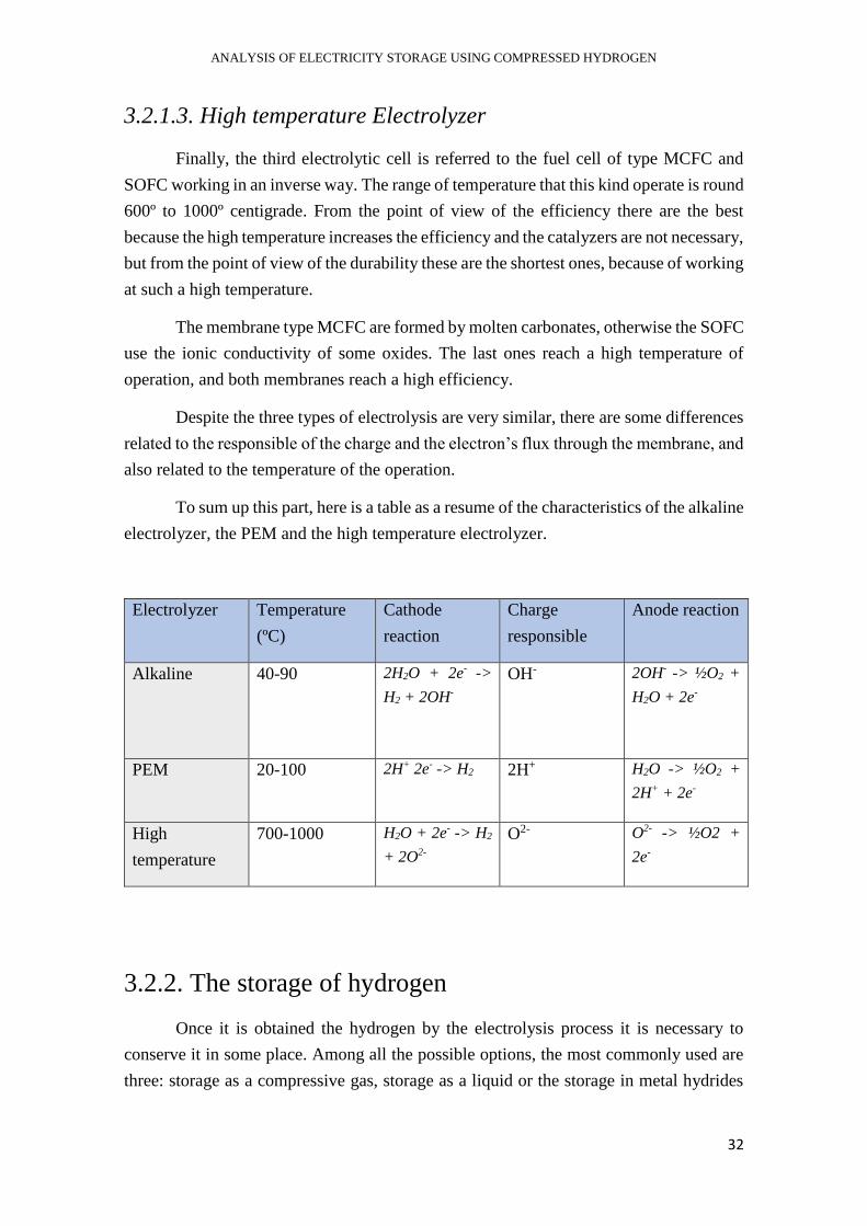
To sum up this part, here is a table as a resume of the characteristics of the alkaline
electrolyzer, the PEM and the high temperature electrolyzer.
Electrolyzer Temperature
(ºC)
Cathode
reaction
Charge
responsible
Anode reaction
Alkaline 40-90 2H2O + 2e- ->
H2 + 2OH-
OH- 2OH- -> ½O2 +
H2O + 2e-
PEM 20-100 2H+ 2e- -> H2 2H+ H2O -> ½O2 +
2H+ + 2e-
High
temperature
700-1000 H2O + 2e- -> H2
+ 2O2-
O2- O2- -> ½O2 +
2e-
3.2.2. The storage of hydrogen
Once it is obtained the hydrogen by the electrolysis process it is necessary to
conserve it in some place. Among all the possible options, the most commonly used are
three: storage as a compressive gas, storage as a liquid or the storage in metal hydrides
ANALYSIS OF ELECTRICITY STORAGE USING COMPRESSED HYDROGEN
33
(MH). Choosing one way or another depends on some factors as the quantity of hydrogen
it is needed to store, the easy accessibility, or other conditions.
In this part there is a resume about the three methods to having an approximative
idea of all of them, beginning by the simplest one until finally reaching the metal hydrides
system, and it is also discussed which one could be the one most suitable in a case of a
little photovoltaic solar plant (PV).
Related to the storage as a compressive gas, as it is said, it is the simplest way to
storage hydrogen because it does not need any transformation, neither any special
condition apart from if it is necessary a compressor to reach the optimal pression.
When the hydrogen is formed in the cathode, it goes outside with a determinate
level of pression. This level, if the quantity of hydrogen to store is not so big, maybe it is
sufficient to be on a cylinder without the necessity of increase more the pression. That
advantage it is found in small quantities, reason that makes the transportation and the use
of the hydrogen very easy. Otherwise, in case that the quantity required is bigger, and
with that level of pression is insufficient to insert all the hydrogen into the cylinder it
exists the possibility to use a compressor. Despite the extra energy to provide, it will reach
an optimal level of pression and the storage could be realized by a cylinder in gas phase.
It is remarkable that this kind of storage is the one that use the vast majority of the
industry in this ambit, due to its simplicity and facilities.
On the other hand, it is also found the storage of hydrogen in liquid form, it is also
called LH2. It is referred to the cryogenic liquid, the phase that is needed to store such a
big quantity of hydrogen in a small volume. Due to its special characteristics of pressure
and low temperatures is not very often use it, in fact it is just used by some special
industries as the ones that are related with petrol and in space centers like the NASA.
Finally, the third method is the one related with metals, usually this association is
made with titanium, iron, manganese, nickel, chrome between others. All of them have
the possibility to react with the hydrogen forming a metal hydride. The general equation
is:
M + H2 -> MH2
Despite the transformation of the hydrogen and its slow recuperation to its purity
form, this way of storage is the most security than the other two, because in this way the
hydrogen is not flammable.
Once it is known the three common forms, focusing the text in the development
of a small renewable plant, it is supposed that the most suitable and optimal one is the
way to storage in a compressive cylinder or tank. Apart from the simplicity to recover the

ANALYSIS OF ELECTRICITY STORAGE USING COMPRESSED HYDROGEN
34
hydrogen, it also depends on the way that we obtain the hydrogen from the cell. If the
device works well and the energy to store is a reasonable quantity, the storage could be
directly without any extra contribution of energy in a compressor.
With the storage system, the relation between production by renewables and
consumer’s demand is partially solved, now it is time to reconvert or reuse this hydrogen
to produce new electricity, or there are other possibilities to reconvert the hydrogen in
other combustible and after that conversion could produce energy. In this following part,
all these aspects are exposed.
3.2.3 Hydrogen applications
Finally, to close this part related to the cycle of hydrogen, the last step is the
process which through the hydrogen the energy can be recovered. That means, how to
generate new energy from the hydrogen that had been stored before.
Here, by the way that the technology is improving they are appearing new forms
to use this hydrogen, but nowadays we can difference three methods that are the most
commons in the industry, and one of them: the fuel cells is in the point of view of all the
industries because it supposes a revelation to the future.
These methods that it is talking about are the methanation process, in which from
the hydrogen is formed methane, the Fischer-Tropsch synthesis’s process for the
formation of hydrocarbons and finally, and the most important one in vision to the future,
the use in Fuel Cells.
These processes can be differenced depending on the direct or indirect use of the
hydrogen to recover the energy. For example, in the methanation and in the synthesis
process, the hydrogen is used to form methane and a synthesis gas to form hydrocarbons.
Once they are formed, this methane and these hydrocarbons will be used by a combustion
to recover the energy that was stored in hydrogen form. Otherwise, with the fuel cells the
hydrogen is directly the fuel, it means that it is not necessary to create other carburant.
Directly with the combustion of hydrogen the Fuel Cell produce energy and water in
vapor form.
This is the main point because, with the directly combustion of hydrogen there is
a process to recover the energy totally respectful with the environment. Thing that makes
ANALYSIS OF ELECTRICITY STORAGE USING COMPRESSED HYDROGEN
35
more interesting and, almost necessary, the introduction of this technology to the actual
energy system.
To having a better idea about the working process of each one there is a resume
about the three of them.
- Methanation:
This process is also known as a Sabatier’s process in which from hydrogen and carbon
dioxide (CO2) is formed methane and water. The process is a combination of two
reactions, an inversion from water-gas and a methanation of CO. As it is showed:
H2 + CO2 <-> CO + H2O
3H2 + CO <-> CH4 + H2O
4H2 + CO2 <-> CH4 +2H2O
This is a process that is usually in a development phase, but despite its capacity to
recover the dioxide of carbon, the combustion of the methane produces it again, so it is
not the main way to recover the energy that the hydrogen contains.
- Fischer-Tropsch’s process:
This one is quite similar to the Sabatier’s one but in this case once it is obtained the
synthesis gas (CO + H2) the process uses it to form new hydrocarbons. These kinds of
processes are very common to make useful the biomass or other combustibles to form
synthesis gas. But from the energetic point and from the environmental one, maybe it is
not the most useful for the hydrogen. That is why the development of technologies about
hydrogen are not so much interested in these processes.
- Fuel Cells:
As it is told before, the technology that has a direct use of the hydrogen to make
possible the recuperation of the energy that the hydrogen contains. Related to its working
mode it is the same that in the electrolysis but in an inverse mode. That is, from the
association of the hydrogen and oxygen and its combustion reaction produces energy and
ANALYSIS OF ELECTRICITY STORAGE USING COMPRESSED HYDROGEN
36
water vapor. Exactly the opposite than in the electrolysis mode where we bring energy to
dissociate the molecule of water.
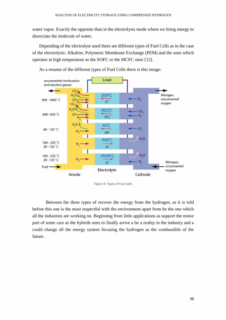
Depending of the electrolyte used there are different types of Fuel Cells as in the case
of the electrolysis: Alkaline, Polymeric Membrane Exchange (PEM) and the ones which
operates at high temperature as the SOFC or the MCFC ones [12].
As a resume of the different types of Fuel Cells there is this image:
Figure 8. Types of Fuel Cells
Between the three types of recover the energy from the hydrogen, as it is told
before this one is the most respectful with the environment apart from be the one which
all the industries are working on. Beginning from little applications as support the motor
part of some cars as the hybrids ones to finally arrive a be a reality in the industry and a
could change all the energy system focusing the hydrogen as the combustible of the
future.

ANALYSIS OF ELECTRICITY STORAGE USING COMPRESSED HYDROGEN
37
3.3. THE DEVELOPMENT OF HYDROGEN IN
THE INDUSTRY
Despite the origins of the electrolysis was two centuries ago, the introduction of
this technology and particularly the introduction of the hydrogen as an energy vector in
the energy system is starting now.
The scale of the generation is related to the electrode’s size, but due to its
modularity and its possibility to associate one each other there are no limits in the design
to big plants of production. Nowadays, there are not so many plants of hydrogen
production that produces to have an electricity recover using Fuel Cells, but this futurist
technology is implanted in some small applications as for example in the cars or in the
small houses to cover a demand.
Related to the cars’ industry there are some companies that are starting to putt on
sold models where the engine is moved by hydrogen energy as for example in Toyota
with the model Toyota Mirai [13]. This revolutionary model could be the beginning of an
industry focused in hydrogen to produce electricity and move an electric motor
incorporated in the device.
On the other hand, there are the small installations to cover the electrical demand
of a house. This kind of application are specially related to introduce the production of
renewables in our daily routine, instead of depending always from the electricity
generated by other usually ways.
This last application is the one that will be exposed in our project. We will focus
the thesis in the object to calculate the hydrogen necessary to cover an electrical demand
of a house during a day. From a model of an electrolyzer connected to a solar panel that
provides it the electricity, we are going to produce the hydrogen necessary to cover the
demand and to storage it by a compression way in tanks.
On the following chapters there is exposed how it is modeled the electrolyzer and
in the following one there is the development to cover the electrical demand of a normal
house.
ANALYSIS OF ELECTRICITY STORAGE USING COMPRESSED HYDROGEN
38
4. THE MODEL OF THE ELECTROLYZER
Once time all the characteristics and the advantages that the introduction of hydrogen
in the energetic system supposes. It is time to focus on the main part of this thesis, to build
a model of electrolyzer from the theorical laws of the electrolysis announced by Faraday.
As well as having other theorical considerations to calculate the number of cells of the
electrolyzer and reaching it efficiency.
With all these parameters the purpose is achieve a model of electrolyzer. We are going
to develop a command in MATLAB in which from different types of direct current we
are going to calculate the mass of hydrogen that it produces. Furthermore, to have a
validation of the command, we are going to introduce some dates from commercial
electrolyzer and with them, the validation of the model it is going to be showed. The
electrolyzers that are being compared are the ones produced by the factory Hydro2Power
SRL and McPhy Hydrogen generators both will be also exposed with more details in this
chapter.
The chapter begins with the theorical development of the electrolysis and how finally
we reach the model built. After that, the commercial electrolyzers are detailed in a table
with its respective information about power and hydrogen production, and in the final
part will be the comparison between the model and the commercial ones.
The aim of the work is making possible the alternative of the hydrogen as an energetic
vector and how it can help to introduce in the energy system the electricity produced by
renewables. That is why our model of electrolyzer is powered by the electricity produced
from a solar panel. Basically, the idea is starting from the energy of the sun through the
hydrogen could produce the necessary energy that we need.
Furthermore, once the electrolyzer has the validation that has a comportment as the
commercial ones, a small situation to cover an electric demand of a house is introduced
as a test for this electrolyzer. This part will be explained in the following chapter.
ANALYSIS OF ELECTRICITY STORAGE USING COMPRESSED HYDROGEN
39
4.1. THEORICAL DEVELOPMENT OF THE
MODEL
The model of the electrolyzer has been created in MATLAB from the basics theorical
steps of the electrolysis. Beginning from the Faraday’s laws and having some
considerations to calculate the number of cells of the electrolyzer and to approach the
efficiency of this, and about the electricity generated in the solar panel.
The command could be developed in some parts, first, related to the inputs it has the
voltage and the current vector with some characteristics values for the intensity in
amperes. After that, with this we calculate the electrical power needed and the solar power
using an approximate factor for the electrical efficiency of a solar panel. Once we know
the power needed, its time to the electrolysis part. Here using the Faraday’s laws, the mols
of hydrogen produced to different values of power are calculated. For the number of cells,
we use an approximation based in the diagram of the voltage in a cell of a fuel cell, and
for the efficiency of the electrolysis. All these parameters to make easily the development
of the command will be explained in this part.
Finally, to complete the command the information about the commercial electrolyzers
is introduced and there is a comparison to validate that our model works properly with a
similar comportment as the commercial ones.
4.1.1. Inputs
There are two inputs in the command the voltage (V) and the current (A), for this last
input we introduce five characteristics values to model the comportment of the hydrogen
production depending of the intensity of small devices.
- Voltage (V):
There is a normal value for the voltage and the one that the commercial
electrolyzers have when they are connected directly to the distribution system of
a house. This is the general voltage, after that in the part of the electrolysis there
is a part where it is in consideration with the voltage of one cell to calculate the
number of cells needed.
V= 230 V

ANALYSIS OF ELECTRICITY STORAGE USING COMPRESSED HYDROGEN
40
- Current (A):
As it is told before we take some different values of current that a usually small
device from 5 to 20KW has. Here there are these typical values of current that
could circulate into the electrolyzer. The current is produced by the solar panels
that produce it in direct DC.
IE_DC = 4; 6.5; 10; 13.5; 20 A
4.1.2. Power calculation
This part is focused in the calculation of the electric power that is needed to produce
the hydrogen and at same time the solar power that can produce this electricity power.
For this reason, an electric efficiency for solar panels is used in the development to
approach the calculation of the solar power needed.
First, we calculate the electric power by the definition of power to direct current
P=𝑉 ∗ 𝐼 to calculate the electric power in watts. After that, with the electrical efficiency
of a solar panel its calculated the solar power that we need [14]. There is the development
of this part:
P=𝑉 ∗ 𝐼
hsolar = 22%
Until this part there is calculated the electric power that the electrolyzer need to the
hydrogen production. But the aim is that the electrolyzer is covered by the electrical
energy that is produced in a solar panel, that is why after the power electrical needed there
is the calculation of the solar power needed through the electrical efficiency of a solar
panel helectric [15]. For this value of efficiency, we choose the one that some studies are
focused on round 22%. It is a high value for the efficiency, but it is in development to
achieve this reality.
Psolar=𝑃
ℎ𝑒𝑙𝑒𝑐𝑡𝑟𝑖𝑐
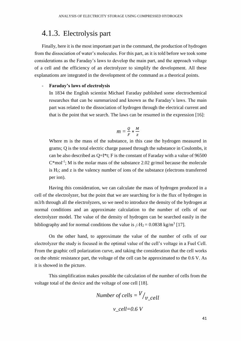
ANALYSIS OF ELECTRICITY STORAGE USING COMPRESSED HYDROGEN
41
4.1.3. Electrolysis part
Finally, here it is the most important part in the command, the production of hydrogen
from the dissociation of water’s molecules. For this part, as it is told before we took some
considerations as the Faraday’s laws to develop the main part, and the approach voltage
of a cell and the efficiency of an electrolyzer to simplify the development. All these
explanations are integrated in the development of the command as a theorical points.
- Faraday’s laws of electrolysis
In 1834 the English scientist Michael Faraday published some electrochemical
researches that can be summarized and known as the Faraday’s laws. The main
part was related to the dissociation of hydrogen through the electrical current and
that is the point that we search. The laws can be resumed in the expression [16]:
m = 𝑄
𝐹∗𝑀
𝑧
Where m is the mass of the substance, in this case the hydrogen measured in
grams; Q is the total electric charge passed through the substance in Coulombs, it
can be also described as Q=I*t; F is the constant of Faraday with a value of 96500
C*mol-1; M is the molar mass of the substance 2.02 gr/mol because the molecule
is H2; and z is the valency number of ions of the substance (electrons transferred
per ion).
Having this consideration, we can calculate the mass of hydrogen produced in a
cell of the electrolyzer, but the point that we are searching for is the flux of hydrogen in
m3/h through all the electrolyzers, so we need to introduce the density of the hydrogen at
normal conditions and an approximate calculation to the number of cells of our
electrolyzer model. The value of the density of hydrogen can be searched easily in the
bibliography and for normal conditions the value is rH2 = 0.0838 kg/m3 [17].
On the other hand, to approximate the value of the number of cells of our
electrolyzer the study is focused in the optimal value of the cell’s voltage in a Fuel Cell.
From the graphic cell polarization curve, and taking the consideration that the cell works
on the ohmic resistance part, the voltage of the cell can be approximated to the 0.6 V. As
it is showed in the picture.
This simplification makes possible the calculation of the number of cells from the
voltage total of the device and the voltage of one cell [18].
Number of cells = 𝑉 𝑣_𝑐𝑒𝑙𝑙⁄
v_cell=0.6 V
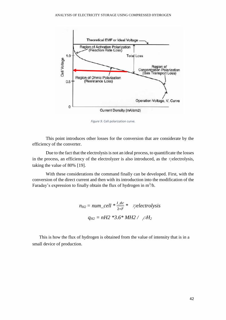
ANALYSIS OF ELECTRICITY STORAGE USING COMPRESSED HYDROGEN
42
Figure 9. Cell polarization curve.
This point introduces other losses for the conversion that are considerate by the
efficiency of the converter.
Due to the fact that the electrolysis is not an ideal process, to quantificate the losses
in the process, an efficiency of the electrolyzer is also introduced, as the helectrolysis,
taking the value of 80% [19].
With these considerations the command finally can be developed. First, with the
conversion of the direct current and then with its introduction into the modification of the
Faraday’s expression to finally obtain the flux of hydrogen in m3/h.
nH2 = num_cell * 𝐼_𝑑𝑐
2∗𝐹 * helectrolysis
qH2 = nH2 *3.6* MH2 / rH2
This is how the flux of hydrogen is obtained from the value of intensity that is in a
small device of production.
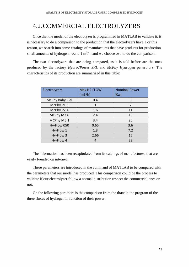
ANALYSIS OF ELECTRICITY STORAGE USING COMPRESSED HYDROGEN
43
4.2. COMMERCIAL ELECTROLYZERS
Once that the model of the electrolyzer is programmed in MATLAB to validate it, it
is necessary to do a comparison to the production that the electrolyzers have. For this
reason, we search into some catalogs of manufactures that have products for production
small amounts of hydrogen, round 1 m3/ h and we choose two to do the comparison.
The two electrolyzers that are being compared, as it is told before are the ones
produced by the factory Hydro2Power SRL and McPhy Hydrogen generators. The
characteristics of its production are summarized in this table:
Electrolyzers Max H2 FLOW (m3/h)
Nominal Power (Kw)
McPhy Baby Piel 0.4 3
McPhy P1,5 1 7
McPhy P2,4 1.6 11
McPhy M3.6 2.4 16
MCPhy M5.1 3.4 20
Hy-Flow 050 0.65 3.6
Hy-Flow 1 1.3 7.2
Hy-Flow 3 2.66 15
Hy-Flow 4 4 22
The information has been recapitulated from its catalogs of manufactures, that are
easily founded on internet.
These parameters are introduced in the command of MATLAB to be compared with
the parameters that our model has produced. This comparison could be the process to
validate if our electrolyzer follow a normal distribution respect the commercial ones or
not.
On the following part there is the comparison from the draw in the program of the
three fluxes of hydrogen in function of their power.

ANALYSIS OF ELECTRICITY STORAGE USING COMPRESSED HYDROGEN
44
4.3. VALIDATION OF THE MODEL
As it is told before to achieve a model that could be considerate appropriate this has
to be validated. For this process we choose a model of validation that consists in
realized a comparison between the other commercial electrolyzers.
To do this part we have introduced the values of the commercial one in the
command and has draw these with our values from the model. The table of results and
the graphic that compares them are:
Electrolyzers Max H2 FLOW (m3/h)
Nominal Power (Kw)
McPhy Baby Piel 0.4 3
McPhy P1,5 1 7
McPhy P2,4 1.6 11
McPhy M3.6 2.4 16
MCPhy M5.1 3.4 20
Hy-Flow 050 0.65 3.6
Hy-Flow 1 1.3 7.2
Hy-Flow 3 2.66 15
Hy-Flow 4 4 22
Model 0.4965 2.71
Model 0.8068 4.40
Model 1.2412 6.77
Model 1.6756 9.14
Model 2.823 13.55
As it is showed, the values are very similar depend on the nominal power that they
use. That is the reason why the graphic corresponds so well.
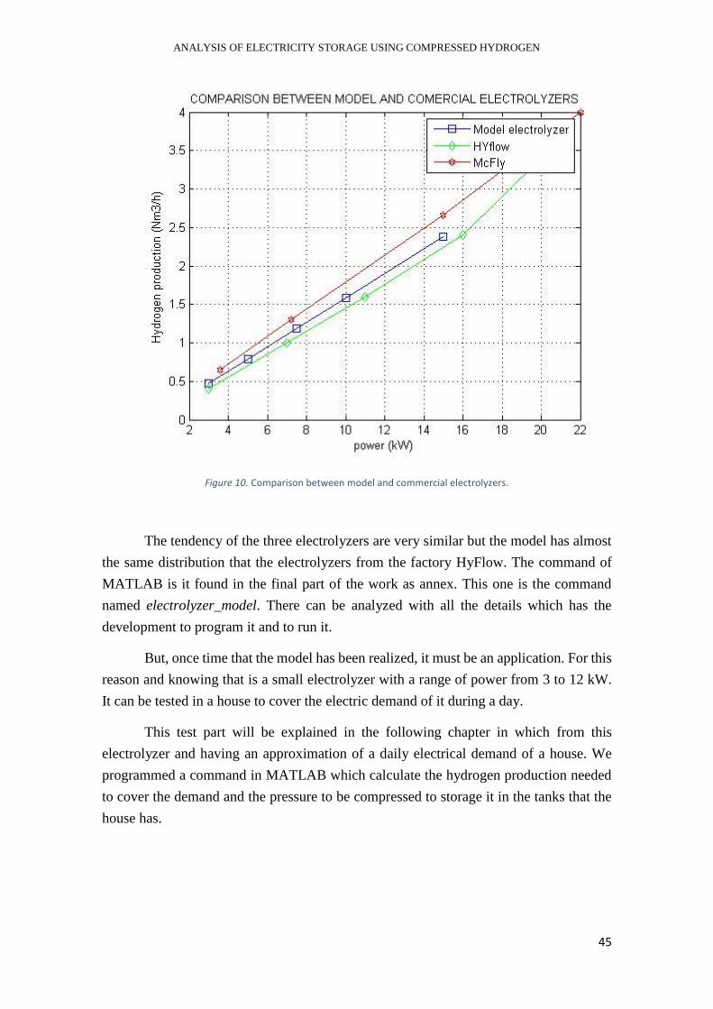
ANALYSIS OF ELECTRICITY STORAGE USING COMPRESSED HYDROGEN
45
Figure 10. Comparison between model and commercial electrolyzers.
The tendency of the three electrolyzers are very similar but the model has almost
the same distribution that the electrolyzers from the factory HyFlow. The command of
MATLAB is it found in the final part of the work as annex. This one is the command
named electrolyzer_model. There can be analyzed with all the details which has the
development to program it and to run it.
But, once time that the model has been realized, it must be an application. For this
reason and knowing that is a small electrolyzer with a range of power from 3 to 12 kW.
It can be tested in a house to cover the electric demand of it during a day.
This test part will be explained in the following chapter in which from this
electrolyzer and having an approximation of a daily electrical demand of a house. We
programmed a command in MATLAB which calculate the hydrogen production needed
to cover the demand and the pressure to be compressed to storage it in the tanks that the
house has.
ANALYSIS OF ELECTRICITY STORAGE USING COMPRESSED HYDROGEN
46
5. ELECTROLYSIS TO COVER AN
ELECTRICAL DEMAND
In the chapter before, the model of an electrolyzer has been realized and validate with
a comparison with other commercial electrolyzer. This point can show that the
introduction of the electrolysis powered by the electric energy generated from solar panels
its possible and could be an alternative for the future as we wanted to show.
The hydrogen can power a lot of installations and has so many applications from the
big industry, the transport among others. But in this case the electrolyzer to production of
hydrogen is a model focused in the small devices and the little demands of energy. For
this reason, the electrolyzer is going to be tested to cover an electrical demand of a
conventional house where are living three persons.
To model this situation, we program other command in MATLAB where from the
input of the daily electrical demand of a house in kWh/day our command provides us the
volume of hydrogen needed to cover this demand and the pressure that it should be stored
if in our installation we have two tanks of 250 liters to store it.
On the first part of the chapter its exposed the development to choose a value for the
electric daily demand depends on the bibliography and other studies focused in this
aspect.
After that, the command in MATLAB is developed with all the theorical
considerations that we took to program it. Since the ideal gas comportment to the
hydrogen, and the consideration of having a refrigerant system to achieve that the
compression of the hydrogen could be realized without relative and significative
difference of temperature.
The full command it is showed, as in the case of the model for the electrolyzer, at the
end in the annex. The name is demand_model.
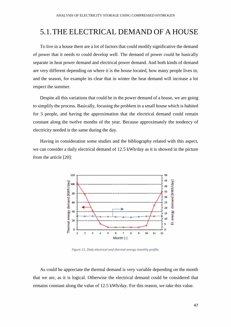
ANALYSIS OF ELECTRICITY STORAGE USING COMPRESSED HYDROGEN
47
5.1. THE ELECTRICAL DEMAND OF A HOUSE
To live in a house there are a lot of factors that could modify significative the demand
of power that it needs to could develop well. The demand of power could be basically
separate in heat power demand and electrical power demand. And both kinds of demand
are very different depending on where it is the house located, how many people lives in,
and the season, for example its clear that in winter the heat demand will increase a lot
respect the summer.
Despite all this variations that could be in the power demand of a house, we are going
to simplify the process. Basically, focusing the problem in a small house which is habited
for 3 people, and having the approximation that the electrical demand could remain
constant along the twelve months of the year. Because approximately the tendency of
electricity needed is the same during the day.
Having in consideration some studies and the bibliography related with this aspect,
we can consider a daily electrical demand of 12.5 kWh/day as it is showed in the picture
from the article [20]:
Figure 11. Dialy electrical and thermal energy monthly profile.
As could be appreciate the thermal demand is very variable depending on the month
that we are, as it is logical. Otherwise the electrical demand could be considered that
remains constant along the value of 12.5 kWh/day. For this reason, we take this value.
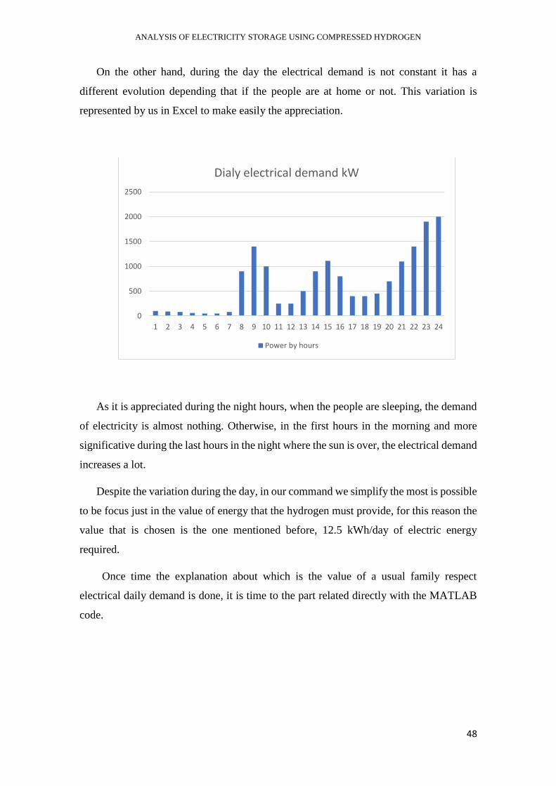
ANALYSIS OF ELECTRICITY STORAGE USING COMPRESSED HYDROGEN
48
On the other hand, during the day the electrical demand is not constant it has a
different evolution depending that if the people are at home or not. This variation is
represented by us in Excel to make easily the appreciation.
As it is appreciated during the night hours, when the people are sleeping, the demand
of electricity is almost nothing. Otherwise, in the first hours in the morning and more
significative during the last hours in the night where the sun is over, the electrical demand
increases a lot.
Despite the variation during the day, in our command we simplify the most is possible
to be focus just in the value of energy that the hydrogen must provide, for this reason the
value that is chosen is the one mentioned before, 12.5 kWh/day of electric energy
required.
Once time the explanation about which is the value of a usual family respect
electrical daily demand is done, it is time to the part related directly with the MATLAB
code.
0
500
1000
1500
2000
2500
1 2 3 4 5 6 7 8 9 10 11 12 13 14 15 16 17 18 19 20 21 22 23 24
Dialy electrical demand kW
Power by hours
ANALYSIS OF ELECTRICITY STORAGE USING COMPRESSED HYDROGEN
49
5.2. THE COMMAND IN MATLAB
As it is mentioned before, in this development in MATLAB the thing that it is wanted
to search is the amount of hydrogen necessary to cover an electrical demand of a house
during a day. And furthermore, having the consideration that the device to storage this
hydrogen is in two tanks of 250 liters, founding also which is the pressure required to
store the hydrogen.
In this part the command is going to be explained by detail and the theorical laws that
are token to develop it. After that, in the following chapter there is a resume of what could
be an example to see which the working mode of the command is.
This command is an integration between the production of hydrogen by the model of
electrolyzer that it has been modeled before, and a storage system based on the
compression of a gas. For this reason, the electrolysis part in the command is the same
that in the chapter before.
5.2.1. Inputs
The aim of the command is to cover an electrical demand of a house, that is why the
main and only input of our command is the value of electrical daily demand that we want
to cover using the hydrogen energy. In this case the value that we choose is the 12.5
kWh/day.
Once this value is known, the command continues making the calculation of the
electrical power needed, and the solar one, and after that it calculates the current that is
running the electrolyzer to produce the hydrogen.
E = 12.5 kWh/day
P = E/24 kW
With this value of power needed, the command continues with the electrolysis as it is
explained before in the part 4.1.3.
ANALYSIS OF ELECTRICITY STORAGE USING COMPRESSED HYDROGEN
50
5.2.2. The Storage System
This is the new and different part respect the command of the electrolyzer. Here, once
through the model of electrolysis the volume of hydrogen is obtained, the thing to know
is at which pressure we are going to store it.
To achieve this porpoise there are to main steps: the volume that we already have to
store it, that is the two tanks of 250 liters of capacity, and the comportment of the
hydrogen depending of the pressure. For this the consideration that we have is that the
hydrogen is an ideal gas and its comportment is based on the equation of ideal gases.
- The ideal gas law:
As all already know the ideal gas law is often written as:
PV = nRT
Where P is the pressure of the gas, V is its volume at this level of pressure and
temperature; n is the number of moles of the gas; T is the temperature of this gas
and R is the constant of the ideal gases with a value of 8.314 J/(K·mol) [11].
This law relations the volume of a gas depending on the temperature and the
pressure that it has.
Usually the compression of a gas is not an isotherm process, so when we compress
the hydrogen to the pressure needed to store it into the tanks it increases its temperature.
But to make the process easy we take the consideration of having a refrigerant device that
could approximate the compression to an isotherm process as it is showed in the picture.
With this consideration the calculation is easy because the variation of the pressure
is the one that makes the variation in the volume of hydrogen. For this reason, having a
constant number of mols of H2, the needed to cover the demand, we calculate the new
density of the hydrogen for this volume of tanks.
d1=d2*𝑃1∗𝑇2
𝑃2∗𝑇1
T1≈T2

ANALYSIS OF ELECTRICITY STORAGE USING COMPRESSED HYDROGEN
51
d1=d2*𝑃1
𝑃2
This variation is represented in the figure of an isotherm variation of an ideal gas [16].
Figure 12. Isotherms of an ideal gas.
With this consideration that the hydrogen has an ideal comportment as it is an
ideal gas, and the introduction of this system of refrigeration that makes possible the
isotherm compression, the values that we obtained after running the program is the
amount of hydrogen needed to cover this demand and the pressure to compress it into the
tanks.
After having an approximation about the command method of working in the
following part we are going to see the results an analyzing them for an input of 12.5
kWh/day electric energy demand.
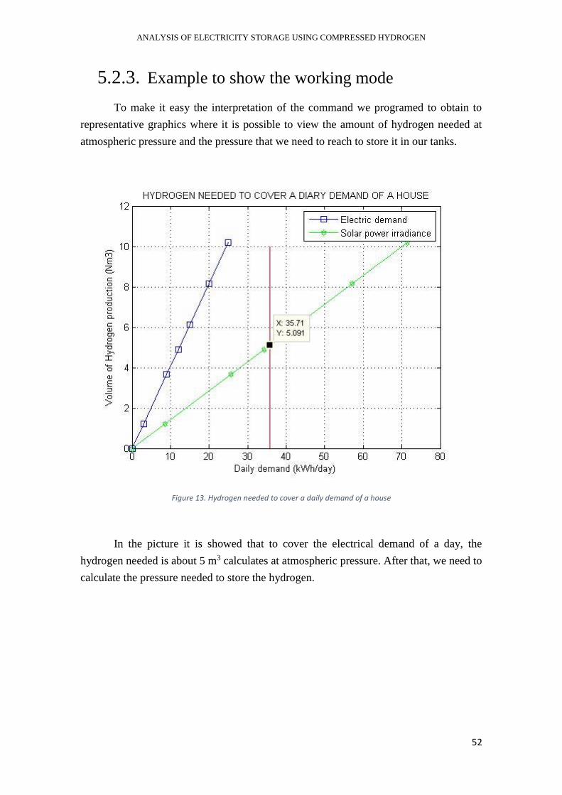
ANALYSIS OF ELECTRICITY STORAGE USING COMPRESSED HYDROGEN
52
5.2.3. Example to show the working mode
To make it easy the interpretation of the command we programed to obtain to
representative graphics where it is possible to view the amount of hydrogen needed at
atmospheric pressure and the pressure that we need to reach to store it in our tanks.
Figure 13. Hydrogen needed to cover a daily demand of a house
In the picture it is showed that to cover the electrical demand of a day, the
hydrogen needed is about 5 m3 calculates at atmospheric pressure. After that, we need to
calculate the pressure needed to store the hydrogen.

ANALYSIS OF ELECTRICITY STORAGE USING COMPRESSED HYDROGEN
53
Figure 14. Level of pressure to store the hydrogen
This is the most representative graphic that we are searching for, as it is showed
for a value of 5.091 m3 the pressure that we need to achieve is 20.36 bar.
To compress the hydrogen there are different forms, first of all and the most
simply is to use a compressor after the electrolysis. But this kind of compression could
suppose an extra cost of the process. For this reason, and now is more frequently is to use
an electrolyzer that could direct product the hydrogen at one determinate level of pressure.
Maybe the initial cost of the electrolyzer is quite elevate, but we will recuperate
the initial inversion because the compressor is not needed.
This example is realized to the value of energy demand that it is mentioned before,
but it is suitable to the small values of energy demand. And as it is reasonable, if the
energy demand is bigger the quantity of hydrogen and the pressure to store it in the tanks
will increase proportionately.

ANALYSIS OF ELECTRICITY STORAGE USING COMPRESSED HYDROGEN
54
6. RESULTS AND CONCLUSIONS
At this point, we can say that hydrogen far from being a distant future can become
the fuel of the future. For small devices, as in the case of copper the energy demand of a
house or feeding a car through fuel cells. But it can grow and become an alternative in all
sectors of generation and production of electricity.
As we did in the demonstration, it is showed that the introduction of the electricity
produced in solar panels with a good efficiency and storage it through hydrogen in tanks
to then recuperate it in a fuel cell, is at least, possible.
Furthermore, it is also proved that for example to cover the electrical daily demand
of a house, having the consideration of 12.5 kWh/day, it is also possible with the
hydrogen. Specifically, this demand needs round 5 m3 of hydrogen in normal conditions.
That could be stored on some tanks at different point of pressure.
However, the most remarkable fact is that with hydrogen as a new form of energy
vector the introduction of renewable energies to the energy system is a more
accomplished reality.
The problem we have mentioned about these technologies is due to their
fluctuation between the electricity production they have and the demand that the
population needs. But it is solved with a storage system, and hydrogen is among all the
storage systems seen the highest energy density present, which allows you to store a lot
of energy in small quantities. Made to favor the supply of different facilities, from small
mechanisms to large plants of electrical production.
With our model we can prove that its possible the integration of the solar power
into the electrolysis process, and furthermore we can prove that our model follows a
normal tendency like the commercial electrolyzer.
The future achievements in this area could make improve the efficiency in
production and in the storage system. But, apart from that it could be a present like it is
showed by the example of covering the electrical daily demand of a house. Just with the
initial cost of the installation we could create a free provider of electricity through the
energy that the hydrogen contains.
And like this example, so much others in which the renewables can supply the
usual way of production electricity. Or moreover include this technology to the transport
in vehicles and camions as companies like Tesla are doing.
The future is unpredictable, but with the advances of the hydrogen its normal to
think that it will be the new revelation, maybe not now, the time will say.

ANALYSIS OF ELECTRICITY STORAGE USING COMPRESSED HYDROGEN
55
7. ANNEXES
7.1. ELECTROLYZER MODEL
% PEM electrolyzer model %
V=230; % voltage [V] ie_dc=[4 6.5 10 13.5 20]; % current [A]
%Power part pelect=(ie_dc.*V)/1000; %electric power (KW) nelect=0.22; %electric efficiency psolar=pelect./nelect % power from solar panels that we need(KW)
%Electrolysis F=96485; %faraday constant nf=0.8; %pem efficiency nc=V/0.6 %number of cells nH2=(nf*nc.*ie_dc)./(2*F); %mol/s of hydrogen %mol/s conversion to m3/h mMH2=2.02; dH2=0.0838; qH2=nH2.*(3.6*mMH2)/dH2
% Comercial electrolyzers qH2_mcphy=[0.4 1 1.6 2.4 3.4]; pmcphy=[3 7 11 16 20]; qH2_hyflow=[0.65 1.3 2.66 4]; phyflow=[3.6 7.2 15 22];
%draw plot(psolar,qH2,pmcphy,qH2_mcphy,phyflow,qH2_hyflow) grid on xlabel('power (kW)') ylabel('Hydrogen production (m3/h)') title('COMPARISON BETWEEN MODEL AND COMERCIAL ELECTROLYZERS') legend('Model electrolyzer','HYflow','McFly')

ANALYSIS OF ELECTRICITY STORAGE USING COMPRESSED HYDROGEN
56
7.2. DEMAND MODEL
%Volum H2 needed to cover daily house's demand
e=12.5%Our energy daily electric demand (KWh/day) p=e/24;%our power needed E=[0 3 9 12 15 20 25]; % Energy daily demand (KWh/day) V=230; P=E./24; % Electric Power we need Ie=1000.*P./(V); ie=1000*p/(V);
%Solar power we need nelect=0.22; %solar efficiency to produce electricity Psolar=P./nelect; %solar power we need psolar=p/nelect; Esolar=Psolar.*24; %daily solar demand esolar=psolar*24
%electrolysis F=96485; %faraday constant nf=0.8; %pem efficiency nc=V/0.6; %number of cells NH2=(nf*nc.*Ie)./(2*F); %mol/s of hydrogen nH2=(nf*nc*ie)./(2*F); %mol/s conversion to m3/h mMH2=2.02; NdH2=0.0838; %densidad a presión atmosférica QH2=NH2.*(3.6*mMH2)/NdH2; %m3/h qH2=nH2*(3.6*mMH2)/NdH2; VH2=QH2.*24; %volum of h2 in m3 vH2=qH2.*24
%storage system MH2=VH2.*NdH2; % mass of hydrogen mH2=vH2*NdH2; Vtank=2*0.1250; %capacity to storage DH2=MH2./Vtank; %density needed to be storage dH2=mH2/Vtank; T1=25; %initial temperature ºC T2=25; %isothermal compression P1=1; %inital pressure bar P2=(DH2./NdH2).*P1; %equation of ideal gases p2=(dH2/NdH2)*P1
%draw figure (1) plot(E,VH2,Esolar,VH2) hold on plot([esolar esolar], [0 12.5], 'red') hold on plot (esolar,vH2,'o-r'); %text (esolar,vH2,'{vH2}') grid on xlabel('Daily demand (kWh/day)') ylabel('Volume of Hydrogen production (m3)') title('HYDROGEN NEEDED TO COVER A DAILY DEMAND OF A HOUSE')

ANALYSIS OF ELECTRICITY STORAGE USING COMPRESSED HYDROGEN
57
legend('Electric demand','Solar demand')
figure (2) plot(P2,VH2) hold on plot([0 45], [vH2 vH2], 'red') hold on plot(p2,vH2,'s-r') grid on xlabel('Pression of compressor (bar)') ylabel('Volume of Hydrogen production(m3)') title('LEVEL OF PRESSURE TO STORE THE HYDROGEN')
ANALYSIS OF ELECTRICITY STORAGE USING COMPRESSED HYDROGEN
58
8. REFERENCES
1. USGS science for a changing world. Hydroeletricpower. Visible body:
water.usgs.gov/edu/hyhowworks.html (access: march 2018)
2. APS Panel on Public Affairs Committee on Energy Environment. Challenges of
electricity storage technologies. American Physical Society. 2007.
3. Eliza Strickland. Sierra Magazaine. Visible body:
https://www.sierraclub.org/sierra/2015-5-september-october/innovate/how-
store-renewable-energy-later/ (access: march 2018)
4. El almacenamiento de electricidad. Gas Natural Fenosa. Energía y medio
ambiente. Juan Ramón Morante. Cap 2.
5. Edward Barbour. Postdoctoral researcher in Energy Storage, University of
Birmingham. Energy Storage Sense. Visible body:
http://energystoragesense.com/superconducting-magnetic-energy-storage-smes
(access: april 2018)
6. European Technology Platform on Renewable Heating and Cooling, (2012)
Strategic Research Priorities for Renewable Heating & Cooling Cross-Cutting
Technology, European Technology Platform on Renewable Heating and
Cooling, Brussels, Report http://www.rhc-platform.org/publications/.
7. Nasir Jafar. Electrochemistry: Electro chemical cell. Visible body:
https://www.tes.com/lessons/zMUo3doki1o5MA/electrochemistry-electro-
chemical-cell (access: april 2018)
8. Jerry Mander and Richard Heinberg. Carbon Institute and International Forum
on Globalization. Visible body: https://www.resilience.org/stories/2012-02-22
(accesss: may 2018)
9. Hydrogen. Wikipedia. Visible body: https://en.wikipedia.org/wiki/Hydrogen
(access: may 2018)
10. A.A. Abou. El Ela. Sizing and Economic Analysis of Hybrid PV/PEMFC.
Visible body: https://www.researchgate.net/figure/Basic-scheme-of-water-
electrolysis-system_fig1_283504861 (access: June 2018)
11. F.M. Sapountzi. Jose Gracia. Electrocatalysts for the generation of hydrogen.
Visible body: https://www.researchgate.net/figure/Operation-principles-of-
alkaline-PEM-proton-exchange-membrane-and-solid-oxide-
water_fig1_308578569 (access: June 2018)
12. University of Cambridge. DoITPoMS. Visible body:
https://www.doitpoms.ac.uk/tlplib/fuel-cells/types.php (access: June 2018)
ANALYSIS OF ELECTRICITY STORAGE USING COMPRESSED HYDROGEN
59
13. Toyota Mirai. Toyota hydrogen vehicle. https://www.toyota.es (access: June
2018)
14. Antonio Gómez Expósito; José Luis Martínez Ramos; Jesús Manuel Riquelme
Santos (1ª ed., 1ª imp. (03/2007)). Fundamentos de teoría de circuitos. Ediciones
Paraninfo. S.A. p. 584. ISBN 9788497324175.
15. Swanson, R. M. (2009). «Photovoltaics Power Up». Science 324 (5929): 891-
2. PMID 19443773. doi:10.1126/science.1169616.
16. Leyes de Faraday de la electrólisis. Wikipedia. Visible body:
https://es.wikipedia.org/wiki/Leyes_de_Faraday (access: June 2018)
17. Seyezhai, R., Mathur, B.L. (2011, April). Mathematical Modeling of Proton
Exchange Membrane Fuel Cell. International Journal of Computer Applications,
VOL. 20, NO. 5.
18. Ching-Ming Lai. Developement of a modular single-phase grid-tie invertir
System for fuel-cell power generation. Visbile body:
https://www.researchgate.net/figure/Typical-fuel-cell-polarization-
curve_fig2_224687448 (access: June 2018)
19. Zuliani N., Taccani R. University of Trieste. Energy Simulation model and
parametric analysis of a micro cogeneration system based on a HTPEM cell and
battery storage.