Embed Size (px)
Citation preview

t Original operating instructions Hammer Drill
�
Art.-Nr.: 42.598.12 I.-Nr.: 11010 BT-ID 1000
Anleitung_BT_ID_1000_SPK7:_ 01.06.2010 8:55 Uhr Seite 1

2
t To avoid damaging the gearbox, the drill / hammer drill selector switch should only bemoved when the machine is at a standstill
Anleitung_BT_ID_1000_SPK7:_ 01.06.2010 8:55 Uhr Seite 2

3
1
2
21 3
6
58
9
7
4
1
3
8
8
Anleitung_BT_ID_1000_SPK7:_ 01.06.2010 8:55 Uhr Seite 3

4
4 5
6 7
8
4
6
1
5
73
B A
2
9
Anleitung_BT_ID_1000_SPK7:_ 01.06.2010 8:55 Uhr Seite 4
5
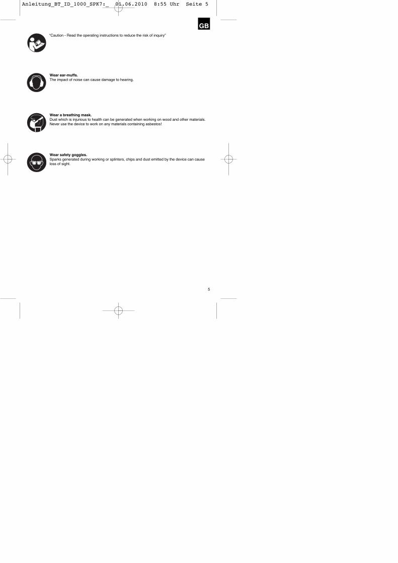
GB“Caution - Read the operating instructions to reduce the risk of inquiry”
Wear ear-muffs.The impact of noise can cause damage to hearing.
Wear a breathing mask.Dust which is injurious to health can be generated when working on wood and other materials.Never use the device to work on any materials containing asbestos!
Wear safety goggles.Sparks generated during working or splinters, chips and dust emitted by the device can causeloss of sight.
Anleitung_BT_ID_1000_SPK7:_ 01.06.2010 8:55 Uhr Seite 5
6
GB� Important!When using equipment, a few safety precautionsmust be observed to avoid injuries and damage.Please read the complete operating manual with duecare. Keep this manual in a safe place, so that theinformation is available at all times. If you give theequipment to any other person, give them theseoperating instructions as well.We accept no liability for damage or accidents whicharise due to non-observance of these instructionsand the safety information.
1. Safety regulations
The corresponding safety information can be foundin the enclosed booklet.
� CAUTION!Read all safety regulations and instructions.Any errors made in following the safety regulationsand instructions may result in an electric shock, fireand/or serious injury.Keep all safety regulations and instructions in asafe place for future use.
2. Layout and item supplied (Fig. 1)
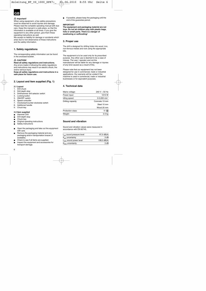
2.1 Layout1. Drill chuck2. Drill depth stop3. Drill/hammer drill selector switch4. Locking button5. ON/OFF switch6. Speed controller7. Clockwise/Counter-clockwise switch8. Additional handle9. Chuck key
2.2 Item supplied� Hammer Drill� Drill depth stop� Chuck key� Original operating instructions� Safety instructions
� Open the packaging and take out the equipmentwith care.
� Remove the packaging material and anypackaging and/or transportation braces (ifavailable).
� Check to see if all items are supplied.� Inspect the equipment and accessories for
transport damage.
� If possible, please keep the packaging until theend of the guarantee period.
IMPORTANTThe equipment and packaging material are nottoys. Do not let children play with plastic bags,foils or small parts. There is a danger ofswallowing or suffocating!
3. Proper use
The drill is designed for drilling holes into wood, iron,non-ferrous metals and rock using the appropriatebits.
The equipment is to be used only for its prescribedpurpose. Any other use is deemed to be a case ofmisuse. The user / operator and not themanufacturer will be liable for any damage or injuriesof any kind caused as a result of this.
Please note that our equipment has not beendesigned for use in commercial, trade or industrialapplications. Our warranty will be voided if themachine is used in commercial, trade or industrialbusinesses or for equivalent purposes.
4. Technical data
Mains voltage: 240 V ~ 50 Hz
Power input: 1010 W
Idling speed: 0-3,000 min-1
Drilling capacity Concrete 13 mm
Steel 10 mm
Wood 25 mm
Protection class: II / �
Weight: 2.3 kg
Sound and vibration
Sound and vibration values were measured inaccordance with EN 60745.
LpA sound pressure level 97,5 dB(A)
KpA uncertainty 3 dB
LWA sound power level 108,5 dB(A)
KWA uncertainty 3 dB
Anleitung_BT_ID_1000_SPK7:_ 01.06.2010 8:55 Uhr Seite 6

7
GBWear ear-muffs.The impact of noise can cause damage to hearing.
Total vibration values (vector sum of three directions)determined in accordance with EN 60745.
Hammer drilling in concrete (handle)Vibration emission value ah = 13.192 m/s2
K uncertainty = 1.5 m/s2
Hammer drilling in concrete (additional handle)Vibration emission value ah = 10.910 m/s2
K uncertainty = 1.5 m/s2
Drilling in metal (handle)Vibration emission value ah = 4.503 m/s2
K uncertainty = 1.5 m/s2
Drilling in metal (additional handle)Vibration emission value ah = 5.372 m/s2
K uncertainty = 1.5 m/s2
Additional information for electric power tools
Warning!The specified vibration value was established inaccordance with a standardized testing method. Itmay change according to how the electric equipmentis used and may exceed the specified value inexceptional circumstances.
The specified vibration value can be used to comparethe equipment with other electric power tools.
The specified vibration value can be used for initialassessment of a harmful effect.
Keep the noise emissions and vibrations to aminimum.� Only use appliances which are in perfect working
order.� Service and clean the appliance regularly.� Adapt your working style to suit the appliance.� Do not overload the appliance.� Have the appliance serviced whenever
necessary.� Switch the appliance off when it is not in use.� Wear protective gloves.
Residual risksEven if you use this electric power tool inaccordance with instructions, certain residualrisks cannot be rules out. The following hazardsmay arise in connection with the equipment’sconstruction and layout:
1. Lung damage if no suitable protective dust maskis used.
2. Damage to hearing if no suitable ear protection isused.
3. Health damage caused by hand-arm vibrations ifthe equipment is used over a prolonged period oris not properly guided and maintained.
5. Before starting the equipment
Before you connect the equipment to the mainssupply make sure that the data on the rating plateare identical to the mains data.
Always pull the power plug before makingadjustments to the equipment.
5.1. Fitting the additional handle (Fig. 2-3/Item 8)The additional handle (8) enables you to achievebetter stability whilst using the hammer drill. Do notuse the tool without the additional handle.The additional handle (8) is secured to the hammerdrill by a clamp. During the handle clockwise tightensthis clamp. Turning it anti-clockwise will release theclamp.� The supplied additional handle (8) must first be
fitted. To do this, the clamp must be opened byturning the handle until it is wide enough for theadditional handle to be slid over the chuck (1)and on to the hammer drill.
� After you have positioned the additional handle(8), turn it to the most comfortable workingposition for you.
� Now turn the handle in the opposite directionagain until the additional handle is secure.
� The additional handle (8) is suitable for both left-handed and right-handed users.
5.2 Fitting and adjusting the depth stop (Fig. 4/Item 2)
The depth stop (2) is held in place by the additionalhandle (8) by clamping. The clamp can be releasedand tightened by turning the handle.� Release the clamp and fit the depth stop (2) in
the recess provided for it in the additional handle.� Set the depth stop (2) to the same level as the
drill bit.� Pull the depth stop back by the required drilling
depth.� Turn the handle on the additional handle (8) until
it is secure.� Now drill the hole until the depth stop (2) touches
the workpiece.
Anleitung_BT_ID_1000_SPK7:_ 01.06.2010 8:55 Uhr Seite 7

8
GB5.3 Fitting the drill bit (Fig. 5)� Always pull the power plug before making
adjustments to the equipment.� Release the depth stop (2) as described in 5.2
and push it towards the drill handle. This providesfree access to the chuck (1).
� Undo the chuck by turning it anti-clockwise withthe supplied chuck key (9).
� To ensure that it is perfectly positioned the drill bitor tool should be inserted as far as possible intothe chuck. After inserting the drill bit or tool,tighten the chuck (1) by turning the chuck key (9)clockwise until the drill bit or tool is secure. Checkthat the drill bit is secure in the chuck (1).
� Check at regular intervals that the drill bit or tool issecure (pull the mains plug).
6. Operation
6.1 ON/OFF switch (Fig. 6/Item 5)� First fit a suitable drill bit into the tool (see 5.3).� Connect the mains plug to a suitable socket.� Position the drill in the position you wish to drill.
To switch on:Press the ON/OFF switch (5)
Continuous operation:Secure the ON/OFF switch (5) with the lockingbutton (4).
To switch off:Press the ON/OFF switch (5) briefly.
6.2 Adjusting the speed (Fig. 6/Item 5)� You can infinitely vary the speed whilst using the
tool.� Select the speed by applying a greater or lesser
pressure to the ON/OFF switch (5).� Select the correct speed: The most suitable
speed depends on the workpiece, the type of useand the drill bit used.
� Low pressure on the ON/OFF switch (5): Lowerspeed (suitable for: small screws and softmaterials)
� Greater pressure on the ON/OFF switch (5):Higher speed (suitable for large/long screws andhard materials)
Tip: Start drilling holes at low speed. Then increasethe speed in stages.
Benefits:� The drill bit is easier to control when starting the
hole and will not slide away.
� You avoid drilling messy holes (for example intiles).
6.3 Preselecting the speed (Fig. 6/Item 6)� The speed setting ring (6) enables you to define
the maximum speed. The ON/OFF switch (5) canonly be pressed to the defined maximum speedsetting.
� Set the speed using the setting ring (6) on theON/OFF switch (5).
� Do not attempt to make this setting whilst the drillis in use.
6.4 Clockwise/Counter-clockwise switch (Fig. 6/Item 7)
� Change switch position only when the drill isat a standstill!
� Switch the direction of the hammer drill using theclockwise/counter-clockwise switch (7):
Direction Switch positionClockwise (forwards and drill) R
Counter-clockwise (reverse) L
6.5 Drill / hammer drill selector switch (Fig. 7/Item 3)
Change switch position only when the drill is at astandstill!
DrillDrill / hammer drill selector switch (3) in the drillposition. (Position A)Use for: Wood, metal, plastic
Hammer drillDrill / hammer drill selector switch (3) in the hammerdrill position. (Position B)Use for: Concrete, rock, masonry
6.6 Tips for working with your hammer drill
6.6.1 Drilling concrete and masonry� Switch the Drill/Hammer drill selector switch (3)
to position B (Hammer drill).� Always use carbide drill bits and a high speed
setting for drilling into masonry and concrete.
6.6.2 Drilling steel� Switch the drill / hammer drill selector switch (3)
to position A (drill).� Always use HSS drill bits (HSS = high speed
steel) and a low speed setting for drilling steel.� We recommend that you lubricate the hole with a
suitable cutting fluid to prevent unnecessary drillbit wear.
Anleitung_BT_ID_1000_SPK7:_ 01.06.2010 8:55 Uhr Seite 8

9
GB6.6.3 Inserting/Removing screws� Switch the Drill/Hammer drill selector switch (3)
to position A (drill).� Use a low speed setting
6.6.4 Starting holesIf you wish to drill a deep hole in a hard material(such as steel), we recommend that you start thehole with a smaller drill bit.
6.6.5 Drilling tiles� To start the hole, switch the drill / hammer drill
selector switch (3) to position A (drill).� Switch the drill / hammer drill selector switch (3)
to position B (hammer drill) as soon as the drillbit has passed through the tiles.
7. Replacing the power cable
If the power cable for this equipment is damaged, itmust be replaced by the manufacturer or its after-sales service or similarly trained personnel to avoiddanger.
8. Cleaning, maintenance andordering of spare parts
Always pull out the mains power plug before startingany cleaning work.
8.1 Cleaning� Keep all safety devices, air vents and the motor
housing free of dirt and dust as far as possible. Wipe the equipment with a clean cloth or blow it with compressed air at low pressure.
� We recommend that you clean the device immediately each time you have finished using it.
� Clean the equipment regularly with a moist cloth and some soft soap. Do not use cleaning agents or solvents; these could attack the plastic parts of the equipment. Ensure that no water can seep into the device.
8.2 Carbon brushesIn case of excessive sparking, have the carbon brushes checked only by a qualified electrician.Important! The carbon brushes should not be replaced by anyone but a qualified electrician.
8.3 MaintenanceThere are no parts inside the equipment which require additional maintenance.
8.4 Ordering replacement parts:Please quote the following data when orderingreplacement parts:� Type of machine� Article number of the machine� Identification number of the machine� Replacement part number of the part requiredFor our latest prices and information please go towww.isc-gmbh.info
9. Disposal and recycling
The unit is supplied in packaging to prevent its beingdamaged in transit. This packaging is raw materialand can therefore be reused or can be returned tothe raw material system.The unit and its accessories are made of varioustypes of material, such as metal and plastic.Defective components must be disposed of asspecial waste. Ask your dealer or your local council.
10. Stockage
Entreposez l’appareil et ses accessoires dans unendroit sombre, sec et à l’abri du gel tout commeinaccessible aux enfants. La température destockage optimale est comprise entre 5 et 30 °C.Conservez l’outil électrique dans l’emballaged’origine.
Anleitung_BT_ID_1000_SPK7:_ 01.06.2010 8:55 Uhr Seite 9

10
t For EU countries only
Never place any electric tools in your household refuse.
To comply with European Directive 2002/96/EC concerning old electric and electronic equipment and its implementation in national laws, old electric tools have to be separated from other waste and disposed of in an environment-friendly fashion, e.g. by taking to a recycling depot.
Recycling alternative to the demand to return electrical devices:As an alternative to returning the electrical device, the owner is obliged to cooperate in ensuring that the device is properly recycled if ownership is relinquished. This can also be done by handing over the used device to a returns center, which will dispose of it in accordance with national commercial and industrial waste management legislation. This does not apply to the accessories and auxiliary equipment without any electrical components which are included with the used device.
�The reprinting or reproduction by any other means, in whole or in part,of documentation and papers accompanying products is permitted onlywith the express consent of ISC GmbH. � Technical changes subject to change
Anleitung_BT_ID_1000_SPK7:_ 01.06.2010 8:55 Uhr Seite 10
11
t GUARANTEE CERTIFICATEDear Customer,
All of our products undergo strict quality checks to ensure that they reach you in perfect condition. In the unlikelyevent that your device develops a fault, please contact our service department at the address shown on thisguarantee card. Of course, if you would prefer to call us then we are also happy to offer our assistance underthe service number printed below. Please note the following terms under which guarantee claims can be made:
1. These guarantee terms cover additional guarantee rights and do not affect your statutory warranty rights.We do not charge you for this guarantee.
2. Our guarantee only covers problems caused by material or manufacturing defects, and it is restricted to therectification of these defects or replacement of the device. Please note that our devices have not beendesigned for use in commercial, trade or industrial applications. Consequently, the guarantee is invalidatedif the equipment is used in commercial, trade or industrial applications or for other equivalent activities. Thefollowing are also excluded from our guarantee: compensation for transport damage, damage caused byfailure to comply with the installation/assembly instructions or damage caused by unprofessionalinstallation, failure to comply with the operating instructions (e.g. connection to the wrong mains voltage orcurrent type), misuse or inappropriate use (such as overloading of the device or use of non-approved toolsor accessories), failure to comply with the maintenance and safety regulations, ingress of foreign bodiesinto the device (e.g. sand, stones or dust), effects of force or external influences (e.g. damage caused bythe device being dropped) and normal wear resulting from proper operation of the device.
The guarantee is rendered null and void if any attempt is made to tamper with the device.
3. The guarantee is valid for a period of 2 years starting from the purchase date of the device. Guaranteeclaims should be submitted before the end of the guarantee period within two weeks of the defect beingnoticed. No guarantee claims will be accepted after the end of the guarantee period. The original guaranteeperiod remains applicable to the device even if repairs are carried out or parts are replaced. In such cases,the work performed or parts fitted will not result in an extension of the guarantee period, and no newguarantee will become active for the work performed or parts fitted. This also applies when an on-siteservice is used.
4. In order to assert your guarantee claim, please send your defective device postage-free to the addressshown below. Please enclose either the original or a copy of your sales receipt or another dated proof ofpurchase. Please keep your sales receipt in a safe place, as it is your proof of purchase. It would help us ifyou could describe the nature of the problem in as much detail as possible. If the defect is covered by ourguarantee then your device will either be repaired immediately and returned to you, or we will send you anew device.
Of course, we are also happy offer a chargeable repair service for any defects which are not covered by thescope of this guarantee or for units which are no longer covered. To take advantage of this service, please sendthe device to our service address.
EINHELL AUSTRALIA PTY LTD6/166 Wellington StreetCollingwood VIC 3066
AustraliaPhone: 1300 922 271
Anleitung_BT_ID_1000_SPK7:_ 01.06.2010 8:55 Uhr Seite 11

EH 06/2010 (01)
Anleitung_BT_ID_1000_SPK7:_ 01.06.2010 8:55 Uhr Seite 12