Embed Size (px)
Citation preview

7/21/2019 Anisotropic PSDM in Practice
http://slidepdf.com/reader/full/anisotropic-psdm-in-practice 1/3
. ASEG 16 th
Geophysical Conference and Exhibition, February 2003, Adelaide Extended Abstracts
Anisotropic prestack depth migration in practice
Peter Whiting* Uwe Klein-Helmkamp Carl NotforsVeritas DGC, Singapore Veritas DGC, Singapore Veritas DGC, Singapore [email protected] [email protected] [email protected]
Osman KhanVeritas DGC, Singapore [email protected]
INTRODUCTION
Prestack depth migration is a commonly used seismic data
processing tool whenever imaging is complicated. More
conventional processing flows make numerous assumptions
that effectively limit effectiveness to areas with small lateral
velocity variations. No such assumptions are made in
prestack depth migration. Assuming the geoscientist can
accurately determine the detailed velocity model, the prestack
depth migration can accurately focus the recorded energy and
produce a precise image.
However, conventional prestack depth migration still contains
assumptions that can hinder accurate focusing of the recorded
seismic energy. One significant assumption is that the layers
and blocks of interval velocities making up the velocity
model are isotropic. This means that it is assumed that the
instantaneous velocity of sound in these layers is independent
of the propagation direction. However, it is well known that
rock layers in sedimentary basins are commonly anisotropic(Thomsen, 1986).
The goal of velocity model building in prestack depth
migration is to define a model accurately enough so that the
raypaths of the seismic energy can be well defined. When the
velocity model is good enough to accurately predict the true
path of the rays, it can be used to precisely focus the energy
from the many soundings into a migrated image. If the
velocity model assumes isotropic propagation, whereas the
reality is anisotropic, then the estimated raypath locations
cannot be completely accurate and the migrated image willlose precision.
In practice, there are two common signs that anisotropy is
needed in the velocity model. Firstly, the resulting depths
achieved from the prestack depth migration do not tie with
those measured by drilling and, secondly, the common-image
point gathers might only flatten on the nearer traces during
model building (Meek et al., 2002). Correct inclusion of
anisotropy into the velocity modelling can correct both of
these problems.
Including anisotropy in the velocity model building process
can be difficult, and is best achieved with the assistance of
well information. The result can be a more preciselyfocussed image for better interpretation and more reliable
amplitude characteristics.
RESULTS OF CONVENTIONAL VELOCITY
MODEL BUILDING
One of the objectives of conventional (isotropic) velocity
model building for prestack depth migration is to achieve flat
common-image point gathers by iteratively updating the
velocity model and migrating. Even after considerable work
and many iterations, it can be found that no velocity change
seems to be able to flatten the farther offsets of the common-
image point gathers. The gathers shown in Figure 1 are
typical of this situation – the near offset traces are flat, but
the energy is overcorrected on the farther offsets.
Residual over-correction of the far offsets is a common sign
of anisotropy. It can never be corrected when the building
blocks of the velocity model are isotropic. It is imperative to
incorporate anisotropic layers in the velocity modelling to
resolve this problem.
SUMMARY
Conventional prestack depth migration involves building
a velocity model for the subsurface using velocities that
are assumed to be isotropic. When the earth is
anisotropic, it is impossible for this conventional earth
model to correctly predict the seismic raypaths and
hence to accurately migrate the recorded data.
Common problems with conventional prestack depth
migration are overcorrected common-image point gathers
and depth misties with available well data.
Applying anisotropic prestack depth migration involves
making some assumptions about the symmetry of the
anisotropy and then determining the vertical velocity and
the anisotropic parameters, delta and epsilon. These
parameters were determined using a combination of well
information, higher moveout analysis and migration
scans.
The results of a successful anisotropic prestack depth
migration tie the available well information, have flat
common-image point gathers and have higher resolution
and improved focussing.
Key words: anisotropy, prestack depth migration

7/21/2019 Anisotropic PSDM in Practice
http://slidepdf.com/reader/full/anisotropic-psdm-in-practice 2/3
. ASEG 16 th
Geophysical Conference and Exhibition, February 2003, Adelaide Extended Abstracts
DEFINING THE ANISOTROPY
After observing the effect of anisotropy, it must be defined so
that it can be incorporated in the velocity model and
raytracing required for prestack depth migration.
Anisotropy occurs whenever the instantaneous velocity of
sound varies with propagation direction. Obviously, this has
the potential to be highly variable and complicated. At
present, anisotropic processing techniques usually make very
simplifying assumptions. It is often assumed that the
anisotropy has transverse symmetry, with either vertical
(VTI), horizontal (HTI) or tilted (TTI) orientation. VTI is the
most common assumption for sedimentary basins, as it
implies that the vertical and horizontal instantaneous
velocities define the axis of symmetry, which is a likely result
of thin beds that have been deposited horizontally.
Even after the simplifying assumption of VTI symmetry has
been made, the vertical velocity and the anisotropyparameters delta and epsilon are required to define the effect
of the anisotropy (assuming that the anisotropy is weak – see
Thomsen, 1986). Delta is the ratio that relates the vertical
velocity and the imaging velocity (i.e. the velocity that
apparently focuses the seismic data for the shorter offsets),
epsilon is the ratio that relates the vertical velocity and the
horizontal velocity. An accurate vertical velocity in
combination with correct deltas will result in depth images
that tie the available well data. Correct epsilons will ensure
that the migrated gathers are flat at the farther offsets (eg.
Hawkins et al., 2001, Hawkins et al., 2002,).
The vertical velocity was derived through careful analysis of
all available well information. The deltas and epsilons weredefined through inversion of second and fourth order moveout
information. This approach uses the moveout equations of
Alkhalifah & Tsvankin (1995) and Grechka & Tsvankin
(1997). Short acquisition cables made it difficult to derive
stable epsilons by pure fourth order analysis. Hence,
additional migration scans with varying epsilons were
required to finetune the results. Subsequently, the vertical
velocity was updated using multiple iterations of layer based
manual velocity analysis and tomography in order to account
for regional velocity variations and velocity anomalies
associated with shallow gas and faulting.
RESULTS OF ANISOTROPIC PSDM
Figure 2 shows the resulting common-image point gathers
after the application of anisotropic prestack depth migration.
The gathers are now flatter on the farther offsets because the
anisotropic velocity model is capable of correctly defining the
true raypaths of the seismic energy. When the true raypaths
are known, it is possible to correctly locate the unmigrated
seismic data in its required migrated (image) location. This
also means that all offsets are now being more correctly
focussed and hence not deteriorating the amplitude
characteristics.
Once anisotropy has been incorporated into the model, furtherrefinements can be made with the use of layer based manual
updating and residual curvature analysis (RCA) tomography.
The tomography is a global model updating procedure that
can provide further refinements of the velocity model. It is
capable of making detailed updates that are very difficult to
achieve with iterative manual updating. Figure 3 shows
migrated common-image point gathers before and after RCA
tomography. The gathers have become even flatter and more
focussed – a good indication that the tomographic updates are
helpful.
CONCLUSIONS
Conventional prestack depth migration uses isotropic velocity
models, however, the real situation in sedimentary basins is
commonly anisotropic. The effects of anisotropy are often
seen as residual far-offset curvature on common-image point
gathers and misties of depth migration outputs with available
well data. These effects are signs that the velocity model is
inadequate for the purpose of accurate depth migration.
Improved depth imaging is achieved by incorporating
anisotropy into the velocity modelling and the prestack depthmigration. At present, anisotropy is introduced under
simplified assumptions (usually VTI symmetry) and two
simple parameters, delta and epsilon. These parameters can
be defined by careful analysis of available well and seismic
information. This approach presents a practical way to
determine and apply anisotropic prestack depth migration.
The results of applying anisotropic prestack depth migration
are flatter common-image point gathers and accurate ties with
well data. However, these are just signs of more accurate
migration and better all-round focussing. This commonly
leads to observations of improved resolution (Meek et al.,
2002) and superior continuity and amplitude integrity.
ACKNOWLEDGEMENTS
We would like to thank PTT Thailand for the permission to
publish the seismic data examples.
REFERENCES
Alkhalifah, T., Tsvankin, I., 1995, Velocity analysis for
transversely isotropic media: Geophysics, 60, 1550-1566
Grechka, V., Tsvankin, I., 1997, Inversion of nonhyperbolic
moveout in transversely isotropic media: 67th Ann. Internat.
Mtg., SEG, Expanded Abstracts, 1686-1688
Hawkins, K., Leggott, R. and Williams, G., 2002, An
integrated geoscience approach to reservior imaging using
anisotropic pre-sdm: 72nd Meeting, SEG, Salt Lake City.
Hawkins, K., Kat, H., Leggott, R. and Williams, G., 2001,
Addressing anisotropy in prestack depth migration : a
southern North Sea case study: 63rd Conference and
Exhibition, EAGE, Amsterdam.
Meek, R.A., Anno, P.D., Brewer, J.D. and Coral, M., 2002,
Anisotropic velocity model building and updating for prestack
depth migration in Indonesia: 72nd Meeting, SEG, Salt Lake
City.
7/21/2019 Anisotropic PSDM in Practice
http://slidepdf.com/reader/full/anisotropic-psdm-in-practice 3/3
Anisotropic Prestack Depth Migration Whiting, Klein-Helmkamp, Notfors and Khan
ASEG 16 th
Geophysical Conference and Exhibition, February 2003, Adelaide. Extended Abstracts
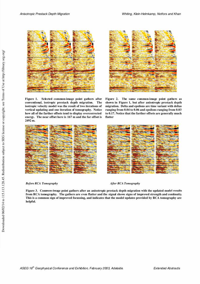
Figure 1. Selected common-image point gathers afterconventional, isotropic prestack depth migration. The
isotropic velocity model was the result of two iterations of
vertical updating and one iteration of tomography. Notice
how all of the farther offsets tend to display overcorrected
energy. The near offset here is 167 m and the far offset is
2492 m.
Figure 2. The same common-image point gathers asshown in Figure 1, but after anisotropic prestack depth
migration. Delta and epsilons are time variant with deltas
ranging from 0.04 to 0.06 and epsilons ranging from 0.03
to 0.17. Notice that the farther offsets are generally much
flatter
Before RCA Tomography After RCA Tomography
Figure 3. Common-image point gathers after an anisotropic prestack depth migration with the updated model results
from RCA tomography. The gathers are even flatter and the signal shows signs of improved strength and continuity.
This is a common sign of improved focussing, and indicates that the model updates provided by RCA tomography arehelpful.