Embed Size (px)
Citation preview
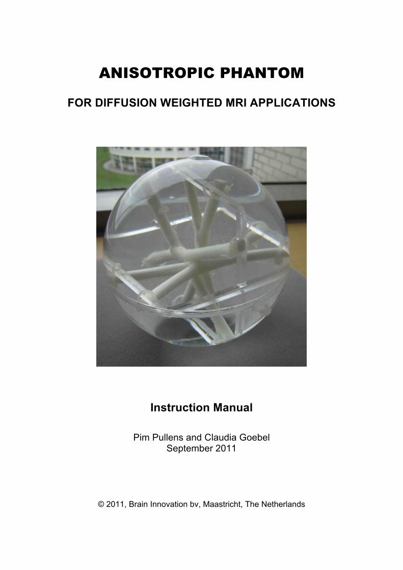
ANISOTROPIC PHANTOM
FOR DIFFUSION WEIGHTED MRI APPLICATIONS
Instruction Manual
Pim Pullens and Claudia Goebel September 2011
© 2011, Brain Innovation bv, Maastricht, The Netherlands

! "!
! #!
TABLE OF CONTENTS
1 PRODUCT CLASSIFICATION AND PURPOSE 4
2 PHANTOM DESIGN AND TEST MEASUREMENT 5 2.1 PHANTOM CONSTRUCTION AND MATERIAL 5 2.2 TEST DTI MEASUREMENT 7
3 CONDITIONS OF USE 13 3.1 GENERAL INSPECTION. SETUP SUGGESTIONS 13 3.2 EXAMPLE MR PROTOCOL AND PROCEDURE 13
4 REFERENCING THE PHANTOM 13
5 SUPPORT 14
6 SAFETY REGULATIONS/ WARNINGS 15 6.1 TEMPERATURE 15 6.2 PHYSICAL HARM 15 6.3 CHEMICAL HARM 15
7 END USER AGREEMENT. WARRANTY CONDITIONS. 16 7.1 KNOWN ISSUES OF NO DEFECT QUALITY 17 7.2 FILLING UP THE PHANTOM 18
8 REFERENCES 18
9 PHANTOM SPECIFICATIONS 19 APPENDIX: DIFFUSION MRI CONCEPTS 20 !
! $!
! "#$%&'()*+,--./.',(.$0),0%)"$-2) The anisotropic PHANTOM is a synthetic physical auxiliary device for diffusion weighted (DW) magnetic resonance imaging (MRI) studies. Diffusion tensor-based fiber tracking is limited in resolving complex white matter of cytoarchitecture, such as diverging or crossing nerve fibers. [1] Fiber properties, measurement parameters, and resulting data quality as well as reconstruction algorithms determine the visualization of fiber bundles, not only its precision or accuracy but also its reproducibility. Hardware phantoms have the advantage of a controllable standard going beyond computer simulations. They can be also subject to simulation studies. In comparison to reference [1] this Anisotropic Phantom contains both 3 straight, nearly orthogonal phantoms and 1 crossing phantom. Its structural design, the polyester fiber material arranged in a particular way in tubes, the isotropic, and aniso-
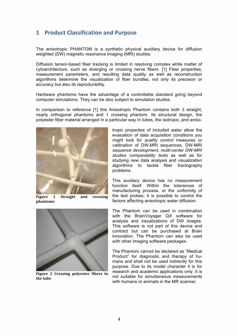
!"#$%&' (' )*%+"#,*' +-.' /%011"-#'2,+-*031
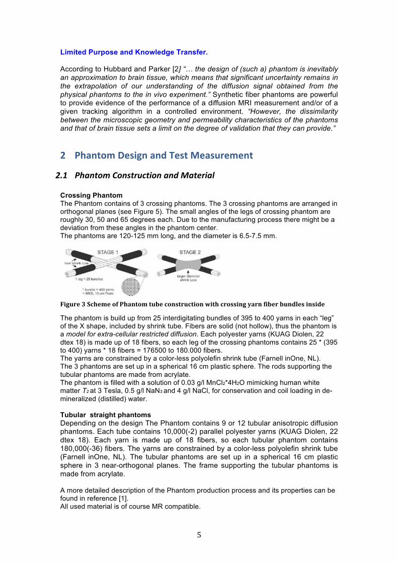
!"#$%&' 4' 5%011"-#' 2067&1*&%' 8"9&%1' "-'*,&'*$9&
tropic properties of included water allow the evaluation of data acquisition conditions you might look for quality control measures or calibration of DW-MRI sequences, DW-MRI sequence development, multi-center DW-MRI studies comparability tests as well as for studying new data analysis and visualization algorithms to tackle fiber tractography problems. This auxiliary device has no measurement function itself. Within the tolerances of manufacturing process, or the uniformity of the test probes, it is possible to control the factors affecting anisotropic water diffusion. The Phantom can be used in combination with the BrainVoyager QX software for analysis and visualizations of DW images. This software is not part of this device and contract but can be purchased at Brain Innovation. The Phantom can also be used with other imaging software packages. The Phantom cannot be declared as “Medical Product” for diagnostic and therapy of hu-mans and shall not be used indirectly for this purpose. Due to its model character it is for research and academic applications only. It is not suitable for simultaneous measurements with humans or animals in the MR scanner.
! %!
Limited Purpose and Knowledge Transfer. According to Hubbard and Parker [2] “… the design of (such a) phantom is inevitably an approximation to brain tissue, which means that significant uncertainty remains in the extrapolation of our understanding of the diffusion signal obtained from the physical phantoms to the in vivo experiment.” Synthetic fiber phantoms are powerful to provide evidence of the performance of a diffusion MRI measurement and/or of a given tracking algorithm in a controlled environment. “However, the dissimilarity between the microscopic geometry and permeability characteristics of the phantoms and that of brain tissue sets a limit on the degree of validation that they can provide.”
3 "4,0($5)62-.70),0%)82-()92,-৘()
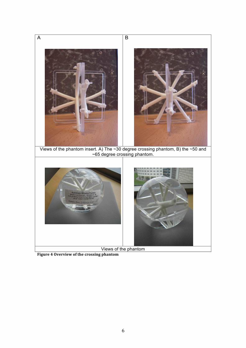
!"# $%&'()*+,)'-(./0(1)'+&'2+3&(4.1&5+ Crossing Phantom The Phantom contains of 3 crossing phantoms. The 3 crossing phantoms are arranged in orthogonal planes (see Figure 5). The small angles of the legs of crossing phantom are roughly 30, 50 and 65 degrees each. Due to the manufacturing process there might be a deviation from these angles in the phantom center. The phantoms are 120-125 mm long, and the diameter is 6.5-7.5 mm.
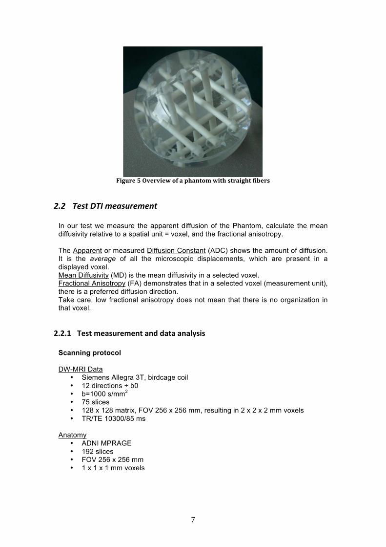
!!"#$%&':')/,&3&'08';,+-*03'*$9&'/0-1*%$/*"0-'<"*,'/%011"-#'7+%-'8"9&%'9$-.6&1'"-1".& The phantom is build up from 25 interdigitating bundles of 395 to 400 yarns in each “leg” of the X shape, included by shrink tube. Fibers are solid (not hollow), thus the phantom is a model for extra-cellular restricted diffusion. Each polyester yarns (KUAG Diolen, 22 dtex 18) is made up of 18 fibers, so each leg of the crossing phantoms contains 25 * (395 to 400) yarns * 18 fibers = 176500 to 180.000 fibers. The yarns are constrained by a color-less polyolefin shrink tube (Farnell inOne, NL). The 3 phantoms are set up in a spherical 16 cm plastic sphere. The rods supporting the tubular phantoms are made from acrylate. The phantom is filled with a solution of 0.03 g/l MnCl2*4H2O mimicking human white matter T2 at 3 Tesla, 0.5 g/l NaN3 and 4 g/l NaCl, for conservation and coil loading in de-mineralized (distilled) water. Tubular straight phantoms Depending on the design The Phantom contains 9 or 12 tubular anisotropic diffusion phantoms. Each tube contains 10,000(-2) parallel polyester yarns (KUAG Diolen, 22 dtex 18). Each yarn is made up of 18 fibers, so each tubular phantom contains 180,000(-36) fibers. The yarns are constrained by a color-less polyolefin shrink tube (Farnell inOne, NL). The tubular phantoms are set up in a spherical 16 cm plastic sphere in 3 near-orthogonal planes. The frame supporting the tubular phantoms is made from acrylate. A more detailed description of the Phantom production process and its properties can be found in reference [1]. All used material is of course MR compatible.
! &!
A B
Views of the phantom insert. A) The ~30 degree crossing phantom, B) the ~50 and ~65 degree crossing phantom.
Views of the phantom !"#$%&'='>?&%?"&<'08'*,&'/%011"-#'2,+-*03
! '!
!!"#$%&'@'>?&%?"&<'08'+'2,+-*03'<"*,'1*%+"#,*'8"9&%1
!"! 64-(+768+*4&-/.4*4'(+ In our test we measure the apparent diffusion of the Phantom, calculate the mean diffusivity relative to a spatial unit = voxel, and the fractional anisotropy. The Apparent or measured Diffusion Constant (ADC) shows the amount of diffusion. It is the average of all the microscopic displacements, which are present in a displayed voxel. Mean Diffusivity (MD) is the mean diffusivity in a selected voxel. Fractional Anisotropy (FA) demonstrates that in a selected voxel (measurement unit), there is a preferred diffusion direction. Take care, low fractional anisotropy does not mean that there is no organization in that voxel.
3:3:! 82-()52,-৘(),0%)%,(,),0,+;-.-) Scanning protocol DW-MRI Data
• Siemens Allegra 3T, birdcage coil • 12 directions + b0 • b=1000 s/mm2 • 75 slices • 128 x 128 matrix, FOV 256 x 256 mm, resulting in 2 x 2 x 2 mm voxels • TR/TE 10300/85 ms
Anatomy
• ADNI MPRAGE • 192 slices • FOV 256 x 256 mm • 1 x 1 x 1 mm voxels
! (!
Gradient directions X Y Z b 0 0 0 0 1 0 0.5 1000 0 0.5 1 1000 0.5 1 0 1000 1 0.5 0 1000 0 1 0.5 1000 0.5 0 1 1000 1 0 -0.5 1000 0 -0.5 1 1000 -0.5 1 0 1000 1 -0.5 0 1000 0 1 -0.5 1000 -0.5 0 1 1000
3:3:3 6,(,)1#$'2--.07) The DTI DICOM data and MPRAGE DICOM data of the Phantom have been imported into BrainVoyagerQX (www.brainvoyager.com). The DTI data have been analyzed in the DTI module. This is the standard protocol for DW-MRI data processing in BrainVoyagerQX. For more information, see the DTI Getting Started Guide available via http://support.brainvoyager.com
1. DMR creation from DW-MRI data 2. tensor calculation, FA and ADC maps on the DMR 3. VMR creation from MPRAGE data 4. co-registration of DMR to VMR 5. VDW creation 6. mask creation on VMR to eliminate background noise 7. tensor, FA, ADC calculation using mask 8. fiber tracking
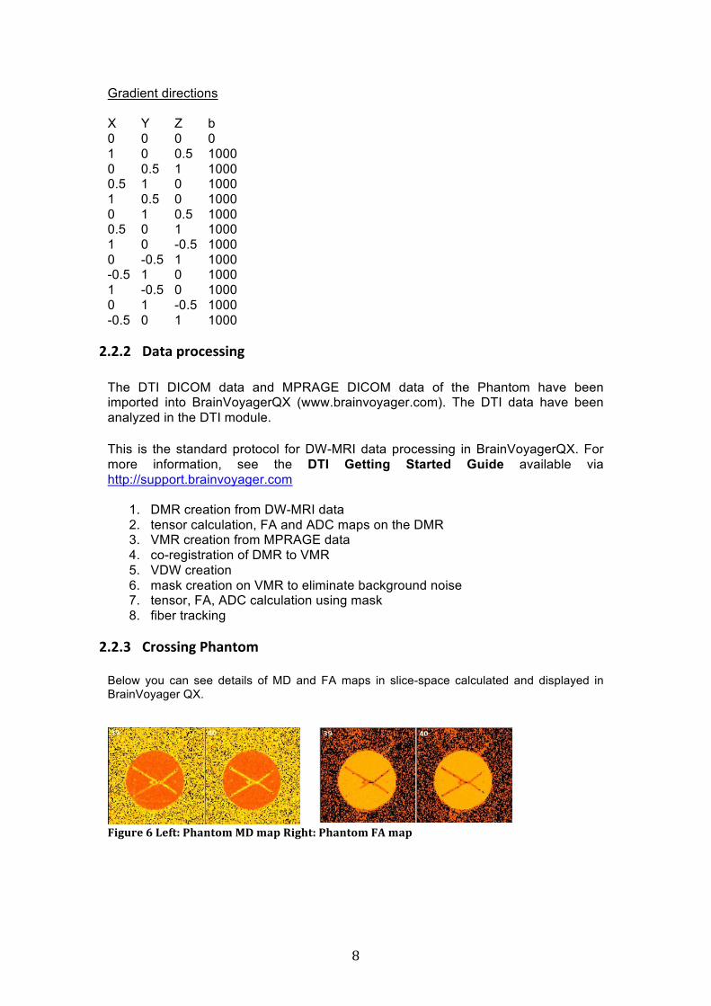
3:3:< *#$--.07)"4,0($5) Below you can see details of MD and FA maps in slice-space calculated and displayed in BrainVoyager QX.
!"#$%&'A'B&8*C';,+-*03'DE'3+2'F"#,*C';,+-*03'!G'3+2

! )!
Below you can see details of MD and FA maps in volume-space in BrainVoyager QX. The data outside of the phantom are masked out by a box.
!"#$%&'H';,+-*03'3&+-'."88$1"?"*7'IDEJ'3+2 '
!"#$%&'K';,+-*03'8%+/*"0-+6'+-"10*%027'3+2
! *+!
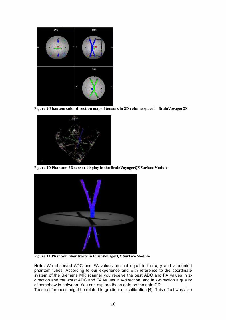
!"#$%&'L';,+-*03'/060%'."%&/*"0-'3+2'08'*&-10%1'"-':E'?06$3&'12+/&'"-'M%+"-N07+#&%OP'
!"#$%&'(Q';,+-*03':E'*&-10%'."126+7'"-'*,&'M%+"-N07+#&%OP')$%8+/&'D0.$6&
!"#$%&'((';,+-*03'8"9&%'*%+/*1'"-'M%+"-N07+#&%OP')$%8+/&'D0.$6& Note: We observed ADC and FA values are not equal in the x, y and z oriented phantom tubes. According to our experience and with reference to the coordinate system of the Siemens MR scanner you receive the best ADC and FA values in z-direction and the worst ADC and FA values in y-direction, and in x-direction a quality of somehow in between. You can explore those data on the data CD. These differences might be related to gradient miscalibration [4]. This effect was also

! **!
observed in human white matter oriented parallel or perpendicular to the main magnetic field [5]. Here more research has to be done. Remark: X, Y, Z direction naming might be different in other MR scanner systems. Check the vendor documentation.
3:3:= >(#,.74()"4,0($5)Below you can see details of MD and FA maps in slice-space calculated and displayed in BrainVoyager QX.
!"#$%&' (4' ;,+-*03' 3&+-' ."88$1"?"*7' IDEJ'3+2
!"#$%&' (:' ;,+-*03' 8%+/*"0-+6' +-"10*%027'I!GJ'3+2
Below you can see details of MD and FA maps in volume-space in BrainVoyager QX. The data outside of the phantom are masked out.
!"#$%&'(=';,+-*03'3&+-'."88$1"?"*7'IDEJ'3+2

! *"!
!"#$%&'(@';,+-*03'8%+/*"0-+6'+-"10*%027'I!GJ'3+2
!"#$%&'(A';,+-*03':E'*&-10%'."126+7'"-'*,&'M%+"-N07+#&%OP')$%8+/&'D0.$6&
!"#$%&' (H' ;,+-*03' 8"9&%' *%+/*1' "-'M%+"-N07+#&%OP')$%8+/&'D0.$6&
.Note: We observed ADC and FA values are not equal in the x, y and z oriented phantom tubes. According to our experience and with reference to the coordinate system of the Siemens MR scanner you receive the best ADC and FA values in z-direction and the worst ADC and FA values in y-direction, and in x-direction a quality of somehow in between. You can explore those data on the data CD. These differences might be related to gradient miscalibration [4]. This effect was also observed in human white matter oriented parallel or perpendicular to the main magnetic field [5]. Here more research has to be done. Remark: X, Y, Z direction naming might be different in other MR scanner systems. Check the vendor documentation.

! *#!
< *$0%.(.$0-)$/)?-2) )))))
9"# :4'4.&5+1'-;40(1)'"+<4(/;+-/==4-(1)'-++ Brain Innovation cannot claim a general, scanner system independent, detailed, and precise instructions for a measurement or study involving the Phantom, since every MRI facility or MR scanner has its own properties and requirements. However, the physical properties of the phantom design shall not change except the measured diffusion anisotropy. * Keep the environmental conditions (e.g. temperature) equal. The results obtained in [1] are valid for room temperature, therefore we recommend scanning at room tem-perature (18-23 deg. Celsius). * Inspect the Phantom regularly before using it. Search for damage or leaks. * Position the phantom in a holder suitable for spherical phantoms or on a bean bag. * The tubular phantoms may be oriented in any direction, but a first measurement should start with the nearly orthogonal tubular phantoms oriented in the x (up-down), y (left – right direction) and z (direction of the bore) axes of the scanner. [Consider also our observations described on p 8]. * Evaluate also the crossing phantom in all 3 directions
9"! >?&*;54+3@+;.)()0)5+&'2+;.)042/.4+ First apply a localizer scan. Ensure that the phantom is in the center of the image and coil. The next step is a diffusion-weighted scan. Use an isotropic voxel size and choose enough slices to cover the whole phantom. We advice to use a b-value of around 1000 s/mm2, but other values may be used as well. Use at least 6 different diffusion directions + a b0 image to reconstruct the diffusion tensor and related measures such as mean diffusivity or fractional anisotropy. Researchers who would like track fibers in BrainVoyager QX need a 3d T1 weighted structural MR scan (1*1*1 mm3) as reference for the DWI data reconstruction (suggested measurement direction - saggital slices).
= @2/2#20'.07)(42)14,0($5)!The "Pullens et. al." paper [1] may be used as a general reference to the phantom in your publication. In your "Methods" section, you can write something like this: "An anisotropic diffusion phantom (Brain Innovation, Maastricht, The Netherlands) was used (Pullens et. al., 2010)."
! *$!
In your "References" section, you can then cite the paper as: Pim Pullens, Alard Roebroeck, and Rainer Goebel (2010). Ground truth hardware phantoms for validation of diffusion-weighted MRI applications JMRI 32: 482-488.
A >&11$#() For further questions or customer support please write to [email protected]. Additional information may also be found at http://www.brainvoyager.com/diffusionphantoms

! *%!
B >,/2(;)@27&+,(.$0-C)DE@FGFH>)
A"# 64*;4.&(/.4+ Keep the phantom away from frost. Do not expose the phantom to extreme heat. It is recommended to store the phantom between 10 and 40 degrees Celsius.
A"! $%B-10&5+%&.*+ To prevent damage to the phantom, do not puncture or drop and avoid contact with sharp objects. In the event the Phantom has a leaky gasket or broken sphere the item should not be used in the MR environment to avoid consequential damages of other equipment.
A"9 ,%4*10&5+%&.*+ The phantom contains a MRI solution, which is harmful to the environment and is dangerous when swallowed. Refer to chemical material safety sheets for disposal of the MRI solution. The solution is not for consumption. This phantom is manufactured in The Netherlands. According to Dutch safety regulations, no warning signs need to be attached to the phantom, since concentrations of dangerous chemicals are low. For the sake of completeness we include the safety sheets for the chemicals in the phantom: MnCl2 · 4 H2O R 22: Harmful if swallowed. R 48: Danger of serious damage to health by prolonged exposure. R 52: Harmful to aquatic organisms. NaCl S 24: Avoid contact with skin. S 25: Avoid contact with eyes. NaN3
R 28: Very toxic if swallowed. R 32: Contact with acids liberates very toxic gas. R 50: Very toxic to aquatic organisms. R 53: May cause long-term adverse effects in the aquatic environment. S 45: In case of accident or if you feel unwell, seek medical advice immediately (show the label where possible). S 60: This material and its container must be disposed of as hazardous waste. S 61: Avoid release to the environment. Refer to special instructions / Safety data sheets.

! *&!
I J0%)?-2#)E7#22520(:)D,##,0(;)*$0%.(.$0-:)) This end user and warranty agreement is a contract between the Manufacturer Brain Innovation (BI), the Seller and the Buyer or End User of the Phantom, as individual or legal entity. It shall protect all professional parties. Intellectual property - The Phantom design (except general design of fiber tubes) and especially the manufacturing process are original ideas of its developer - WLPM Pullens (Brain Innovation bv, Maastricht, The Netherlands) [1]. Copyright - WLPM Pullens and Brain Innovation bv, Universiteitssingel 40, 6229 ER Maastricht, The Netherlands. Distribution right Brain Innovation possesses international distribution rights for the Phantom exclusively. This right is extended to BI’s reseller network based on sales agreements. Applicable law The Phantom is developed and manufactured at Brain Innovation in Maastricht, The Netherlands. Brain Innovation’s jurisdiction is Maastricht, NL. Brain Innovation is also first Seller of the device. In the case there are more Sellers included in the distribution process refer to their sales agreements. Certain rules might be different in other countries. Warranty of merchantability Brain Innovation warrants that the phantom supplied under this contract shall at the date of delivery:
- be free from defects in material; - be free from defects in workmanship; - be free from defects inherent in design, including but not limited to the
selection of material, and be fit for the purpose described in section 1. If any defect provably present in any of the items on the date of delivery comes to light during the defects liability period, then the Buyer shall forthwith notify Brain Innovation or the Seller. Brain Innovation without undue delay, shall at his own risk and cost make good the defect. Brain Innovation’s liability for defects is subject to the Buyer having adherent to all procedures and instructions applicable to the “Conditions of Use” of the Phantom, and expressly excludes damage to the goods caused by fair wear and tear or by misuse occurring after delivery.
! *'!
C"# D')E'+1--/4-+)F+')+24F40(+G/&51(B++
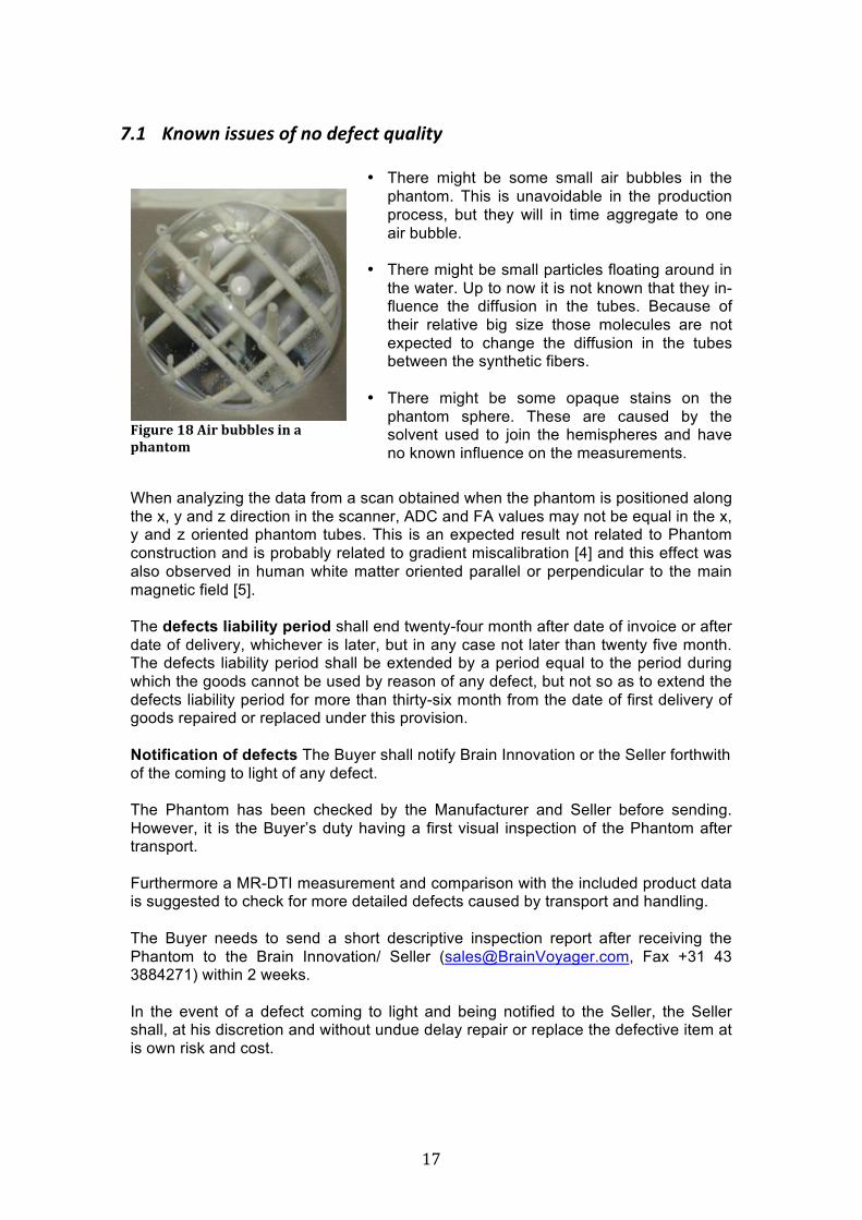
!!"#$%&'(K'G"%'9$996&1'"-'+'2,+-*03
• There might be some small air bubbles in the phantom. This is unavoidable in the production process, but they will in time aggregate to one air bubble.
• There might be small particles floating around in
the water. Up to now it is not known that they in-fluence the diffusion in the tubes. Because of their relative big size those molecules are not expected to change the diffusion in the tubes between the synthetic fibers.
• There might be some opaque stains on the
phantom sphere. These are caused by the solvent used to join the hemispheres and have no known influence on the measurements.
When analyzing the data from a scan obtained when the phantom is positioned along the x, y and z direction in the scanner, ADC and FA values may not be equal in the x, y and z oriented phantom tubes. This is an expected result not related to Phantom construction and is probably related to gradient miscalibration [4] and this effect was also observed in human white matter oriented parallel or perpendicular to the main magnetic field [5]. The defects liability period shall end twenty-four month after date of invoice or after date of delivery, whichever is later, but in any case not later than twenty five month. The defects liability period shall be extended by a period equal to the period during which the goods cannot be used by reason of any defect, but not so as to extend the defects liability period for more than thirty-six month from the date of first delivery of goods repaired or replaced under this provision. Notification of defects The Buyer shall notify Brain Innovation or the Seller forthwith of the coming to light of any defect. The Phantom has been checked by the Manufacturer and Seller before sending. However, it is the Buyer’s duty having a first visual inspection of the Phantom after transport. Furthermore a MR-DTI measurement and comparison with the included product data is suggested to check for more detailed defects caused by transport and handling. The Buyer needs to send a short descriptive inspection report after receiving the Phantom to the Brain Innovation/ Seller ([email protected], Fax +31 43 3884271) within 2 weeks. In the event of a defect coming to light and being notified to the Seller, the Seller shall, at his discretion and without undue delay repair or replace the defective item at is own risk and cost.

! *(!
In the event of a defect coming to light (e.g. leaky gasket or broken sphere) the item should not be used in the MR environment to avoid consequential damages of other equipment. Implied warranty of fitness/ warranty for a particular purpose As evaluated and described in reference 1 the anisotropic Phantom is suitable for the in section 1 circumscribed purpose. The authors indicate expressively to the limitations of knowledge transfer collected with the anisotropic Phantom to true organic tissue (nerve fiber bundles). That will be subject of further studies.
C"! H1551'=+/;+(%4+;%&'()*+In some cases (e.g. an air bubble) it might be necessary to fill up the phantom. In the phantom package, a vial with the filling solution and a 20ml syringe are supplied. Put the phantom on a stable, water resistant surface so it won’t tip over. A good stable base is a roll of duct tape or the like. Gently unscrew the plastic screw on the top using a screwdriver of appropriate size. Fill the syringe with some of the solution and fill up completely. Then, place the screw back on (don’t forget the O-ring) and very gently, without using force, turn the screw until you feel some resistance. Wipe up any spillover.
K @2/2#20'2-) [1] Pim Pullens, Alard Roebroeck, and Rainer Goebel (2010). Ground truth hardware phantoms for validation of diffusion-weighted MRI applications JMRI 32: 482-488. [2] PL Hubbard, GJM Parker (2009). Validation of Tractography. In H Johansen-Berg, TEJ Behrens, Diffusion MRI: From Quantitative Measurement to In vivo Neuroanatomy. Elsevier. [3] H Johansen-Berg, TEJ Behrens (2009). Diffusion MRI: From Quantitative Measurement to In vivo Neuroanatomy. Elsevier. [4] Nagy, Z, Weiskopf, N, Alexander, D, and Deichmann, R. (2007). A method for improving the performance of gradient systems for diffusion-weighted MRI. MRM 58:763-768. [5] J Lee, K Shmueli, M Fukunaga, P van Gelderen, H Merkle, AC Silva, JH Duyn (2010). Sensitivity of MRI Resonance Frequency to the Orientation of Brain Tissue Microstructure, PNAS, 107(11):5130-5
! *)!
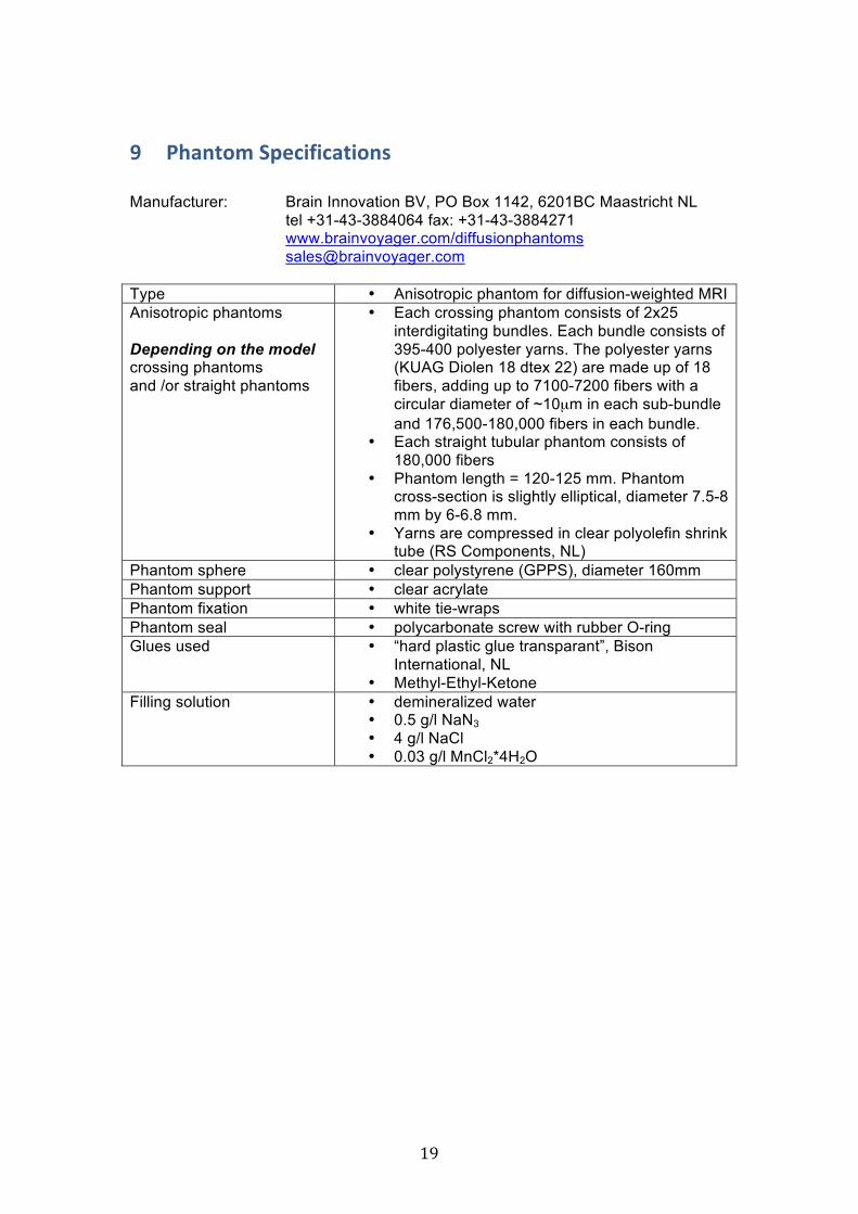
L )"4,0($5)>12'./.',(.$0-) Manufacturer: Brain Innovation BV, PO Box 1142, 6201BC Maastricht NL
tel +31-43-3884064 fax: +31-43-3884271 www.brainvoyager.com/diffusionphantoms [email protected] Type • Anisotropic phantom for diffusion-weighted MRI Anisotropic phantoms Depending on the model crossing phantoms and /or straight phantoms
• Each crossing phantom consists of 2x25 interdigitating bundles. Each bundle consists of 395-400 polyester yarns. The polyester yarns (KUAG Diolen 18 dtex 22) are made up of 18 fibers, adding up to 7100-7200 fibers with a circular diameter of ~10µm in each sub-bundle and 176,500-180,000 fibers in each bundle.
• Each straight tubular phantom consists of 180,000 fibers
• Phantom length = 120-125 mm. Phantom cross-section is slightly elliptical, diameter 7.5-8 mm by 6-6.8 mm.
• Yarns are compressed in clear polyolefin shrink tube (RS Components, NL)
Phantom sphere • clear polystyrene (GPPS), diameter 160mm Phantom support • clear acrylate Phantom fixation • white tie-wraps Phantom seal • polycarbonate screw with rubber O-ring Glues used • “hard plastic glue transparant”, Bison
International, NL • Methyl-Ethyl-Ketone
Filling solution • demineralized water • 0.5 g/l NaN3 • 4 g/l NaCl • 0.03 g/l MnCl2*4H2O
!
! "+!
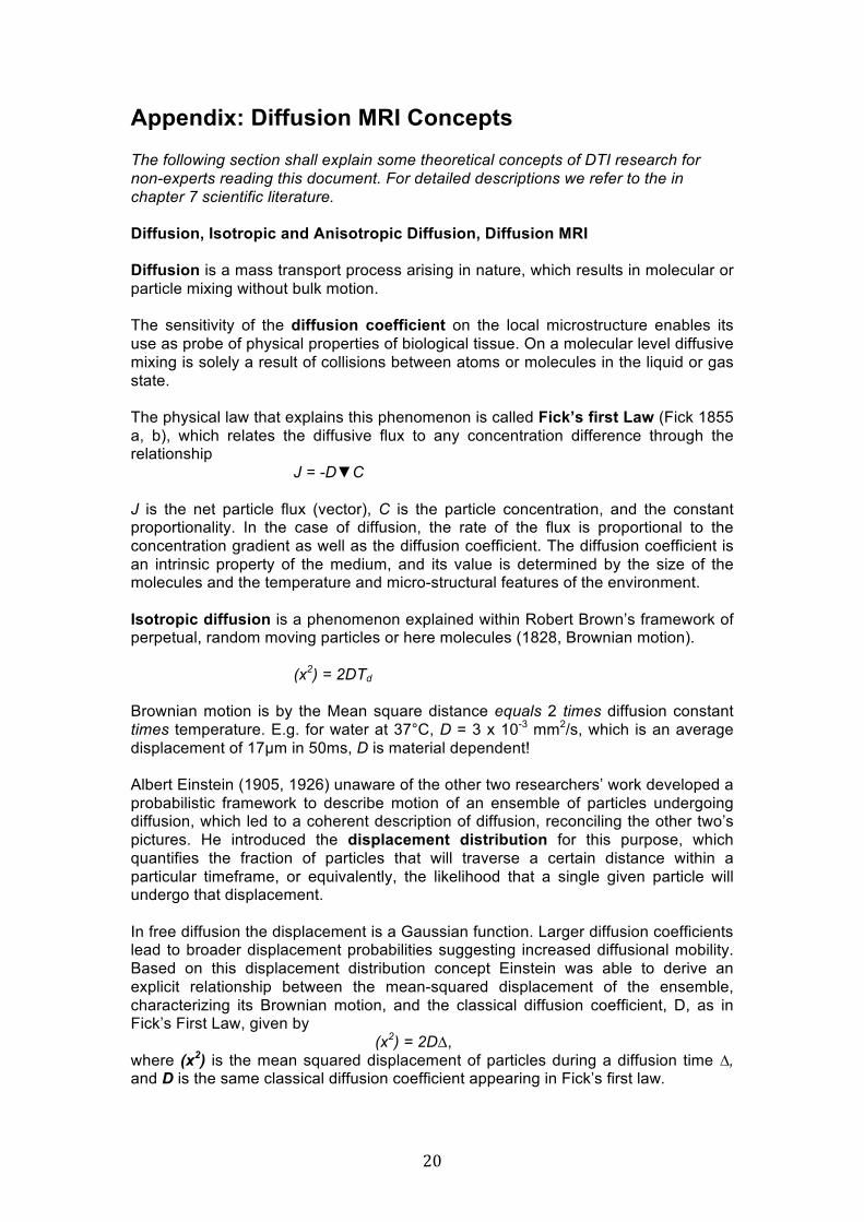
Appendix: Diffusion MRI Concepts The following section shall explain some theoretical concepts of DTI research for non-experts reading this document. For detailed descriptions we refer to the in chapter 7 scientific literature. Diffusion, Isotropic and Anisotropic Diffusion, Diffusion MRI Diffusion is a mass transport process arising in nature, which results in molecular or particle mixing without bulk motion. The sensitivity of the diffusion coefficient on the local microstructure enables its use as probe of physical properties of biological tissue. On a molecular level diffusive mixing is solely a result of collisions between atoms or molecules in the liquid or gas state. The physical law that explains this phenomenon is called Fick’s first Law (Fick 1855 a, b), which relates the diffusive flux to any concentration difference through the relationship J = -D!C J is the net particle flux (vector), C is the particle concentration, and the constant proportionality. In the case of diffusion, the rate of the flux is proportional to the concentration gradient as well as the diffusion coefficient. The diffusion coefficient is an intrinsic property of the medium, and its value is determined by the size of the molecules and the temperature and micro-structural features of the environment. Isotropic diffusion is a phenomenon explained within Robert Brown’s framework of perpetual, random moving particles or here molecules (1828, Brownian motion). (x2) = 2DTd Brownian motion is by the Mean square distance equals 2 times diffusion constant times temperature. E.g. for water at 37°C, D = 3 x 10⁻³ mm2/s, which is an average displacement of 17µm in 50ms, D is material dependent! Albert Einstein (1905, 1926) unaware of the other two researchers’ work developed a probabilistic framework to describe motion of an ensemble of particles undergoing diffusion, which led to a coherent description of diffusion, reconciling the other two’s pictures. He introduced the displacement distribution for this purpose, which quantifies the fraction of particles that will traverse a certain distance within a particular timeframe, or equivalently, the likelihood that a single given particle will undergo that displacement. In free diffusion the displacement is a Gaussian function. Larger diffusion coefficients lead to broader displacement probabilities suggesting increased diffusional mobility. Based on this displacement distribution concept Einstein was able to derive an explicit relationship between the mean-squared displacement of the ensemble, characterizing its Brownian motion, and the classical diffusion coefficient, D, as in Fick’s First Law, given by (x2) = 2D", where (x2) is the mean squared displacement of particles during a diffusion time !, and D is the same classical diffusion coefficient appearing in Fick’s first law.

! "*!
Following Assaf and Cohen [3], Diffusion MRI has the potential to infer features of complex tissue structures as it actually measures the mean displacement of water molecules rather than their diffusion coefficient. Thus, assuming that the displacement of water molecules is affected by tissue microstructure, diffusion MRI should become sensitive to structural parameters of the tissue. … Biological cells may hinder the Brownian motion (free motion) of extra-cellular water molecules. Inside each cell, diffusion may be envisioned to be restricted by the cellular membranes. Non-free motion may be anisotropic.
Diffusion types. Diffusion directions in neural fibers. Water is more restricted in its diffusion perpendicular to the axons, than it is parallel to the axons. I.e. Diffusion becomes anisotropic: it is larger along some directions than others. D! > D"
Three magnitudes, three directions.
From diffusion to the tensor model.
Isotropic diffusion is free diffusion of molecules with same likelihood to move in all directions resulting in a modeled round diffusion sphere. Anisotropic diffusion is represented as a diffusion ellipsoid reflecting diffusion parallel or perpendicular to certain structures, in biological tissue/ neural fibers – extra-cellular as well intra-cellular, mainly in the axons.
There is observed evidence that restricted diffusion is apparent in neuronal tissues

! ""!
with water molecule diffusion within the axons as the main contributor to it (80%) versus 20% extra-cellular. The intracellular diffusion is the principle source. Thus, restricted diffusion as measured by MRI enables quantitative, morphologically related, parameters such as the axon density and axon diameter distribution to be extracted.
Cell probes of nerve/ axonal bundles. Different analysis routines and their bio-physical meaning along with selected applications can be tested with the physical synthetic phantom in its defined structural parameters described in section 2.1. Measured/ apparent diffusion constant. The measured diffusion constant is the apparent diffusion constant, not real diffusion constant. It is the statistical average of all the microscopic displacement distributions which are present in a displayed voxel (spatial unit). It is dependent on the measurement sequence. To probe the direction in tissue we apply gradients in several directions. The following slides offer a quick discourse through the mathematics:
We need at least to measure 6 directions to fill the tensor.
From tensor to scalar measures.

! "#!
Studying Fiber Configurations and Tractography Seunarine and Alexander are giving a theoretical overview of this topic in “Multiple Fibers: Beyond the Diffusion Tensor”, see [3]. One central goal when we analyze DTI data is to discriminate between discrete and continuous fibers in special fiber configurations for fiber tracking, like parallel fibers, fanning, bending, acute crossing and general crossing configurations. Unfortunately, DTI acquisitions produce only a discrete, coarsely sampled representation [v (I, j, k)] of the continuous fiber tract direction field [v (x, y, z)]. That makes certain configurations extremely difficult to classify (e.g. crossing versus touching). Our goal is to reconstruct trajectories of bundles of fibers from the direction field extracted from diffusion tensor data in the phantom configuration. This can be done within BrainVoyager QX or with other software algorithms. The discrimination of such problematic properties even in a synthetic phantom are dependent on the DTI acquisition sequence, magnetic field properties (e.g. homogeneity) and other acquisition parameters, voxel resolution, position of the phantom relative to the magnetic field, post-hoc data correction algorithms, reconstruction algorithms beside other variables adding in in-vivo measurements of human brain structure (e.g. head motion etc.).
A B Voxel-based DTI data in volume-space with tensors; B: Discrete, coarsely sampled representation [v (I, j, k)] of the continuous fiber tract direction field [v (x, y, z)] and reconstruction of trajectory fiber bundles.


![933 dji phantom-4 spec-sheet-rev[1] - PLASTICASE · 2019. 10. 23. · 933 DJI™ PHANTOM 4 For all DJI™ Phantom 4 models Phantom 4 Phantom 4 Pro Phantom 4 Pro + 2.0 Phantom 4 RTK](https://img.dokumen.tips/doc/110x75/60c827405a7e465133218fc4/933-dji-phantom-4-spec-sheet-rev1-plasticase-2019-10-23-933-djia-phantom.jpg)