Embed Size (px)
Citation preview

EC 316: MICROPROCESSOR LAB PROJECT
NETAJI SUBHAS INSTITUTE OF TECHNOLOGY
ANIMAL TRACKER This 8085-based project can be used in barns to keep a track of animals inside it. Its basically designed for the farmers so that,if any animal goes out of the barn then the authorized person can easily get to know because of the alarm which will start ringing.
Submitted by-
Kartik Kumar: 77/EC/13
Praveen Ranjan Pandey: 124/EC/13

INTRODUCTION
In this particular project we have designed a hardware that will take care of animals that are kept in a
particular area by the farmers in villages. This has been implemented by having a counter at the entry
gates of the barn which will increment at every time an animal goes in. After all animals have entered
in the barn, the count will be stored and accordingly if at any instant of time , the counter gets
decremented, then alarm would start ringing or basically in respect to our project a buzzer would start
beeping. In this way the farmer or the authorized person would get to know and would take the
required action accordingly so that the animal doesn’t go out of his range.
PROJECT DESCRIPTION
The animal tracker is a device which can be used in barns to facilitate the farmer to not to look
constantly in the Barn and count animals ,rather just having a buzzer with him and listening to it that
when it beeps because it will give the symbol that an animal has gone out.
When an animal enters the door, the counter adds one to the total tally. When an animal leaves, it
subtracts one and causes the buzzer to beep.
The device made on Intel 8085 microprocessor platform majorly consists of three parts:
1. The counter: Two lasers and LDRs (light dependent resistors) are used for the entry and
exit detection. Every time there is an entry counter increments by one and for exit it
decrements by one. LDR, also known as photo- resistor is a light controlled variable
resistor. Its resistance decreases with increasing incident light intensity (given through
laser in the project). So every time an obstruction occurs (an animal crossing the gate) in
the path of laser light reaching the LDR, an ORed signal/ interrupt of both the LDRs is sent
to the interrupt RST6.5, implying an entry or exit has occurred in/out of the shop. Whether
it is an entry or an exit is determined by the code logic (the individual signals of both LDRs
are also sent to the port B of IC 8255).

2. Display mode: This part consists of viewing the count at every entry and storing it in
memory at a particular address and according if it is getting decremented at any instant
then making the buzzer beep for a long time.
BOARD LAYOUT
Schematic

Board file

The soldered board with all the components

The board with all the setup:
With all the set up:

FLOW CHARTS
Interrupts flow chart:
INTERRUPT RST 7.5
INCREMENT
REGISTER E
RETURN
INTERRUPT RST 5.5
SET FLAG
RETURN

INTERRUPT RST 6.5
READ PB
B1 IS SET
PROCESS B1 TO B0
READ PB
READ PB
PROCESS B0 TO B1
RETURN
DELAY
COUNTER = 0
B0?
B0? B1? YES YES
YES
NO
NO
NO
YES
NO
DELAY
COUNTER 0 =
NO
YES
DECREMENT
INCREMENT COUNT


START
INITIALISE LCD
ENABLE INTERRUPTS
COMPARE REGISTER E
1 SECOND
ELAPSED
DISPLAY
CHECK FOR 1 MIN
1 MIN
ELAPSED
DISPLAY
1 HR
ELAPSED
DISPLAY
YES
YES
YES
NO
NO
NO

MAIN PROGRAM .ORG 0000H
LXI SP,0000H
LXI B,0000H
MVI A,090H ;8255 INITIALISATION
0004 0005 D3 03 OUT 003H
0005 0007 3E 30 INIT:MVI A,030H
0006 0009 47 MOV B,A
0007 000A CD 80 00 CALL OUTPUT
0008 000D CD 7C 00 CALL CMDOUT
0009 0010 CD 7C 00 CALL CMDOUT
0010 0013 3E 38 MVI A,038H ;8 BIT, 2 LINES, 5X8 DISP
0011 0015 CD 7C 00 CALL CMDOUT
0012 0018 3E 08 MVI A,008H ;DISPLAY OFF
0013 001A CD 7C 00 CALL CMDOUT
0014 001D 3E 01 MVI A,001H ;CLEAR DISPLAY
0015 001F CD 7C 00 CALL CMDOUT
0016 0022 3E 06 MVI A,006H ;ENTRY MODE SET, SHIFT AND INCREMENT CURSOR
0017 0024 CD 7C 00 CALL CMDOUT
0018 0027 3E 0C MVI A,00CH ;DISPLAY ON CURSOR, BLINKING OFF
0019 0029 CD 7C 00 CALL CMDOUT
START:IN 002H ; PORT C DATA IN
ANI 0C0H ; MASKING ALL BITS EXCEPT D6 AND D7
CPI 000H ; CHECK IF CHANGE HAS OCCURED
JC CHANGE ;VALUE>00H MEANS CHANGE HAS OCCURED

JMP START
CHANGE:ORA A ; RESETTING FLAG
CPI 040H; LASER 1 IS HIGH
JZ ENTER;
JMP LEAVE
ENTER:IN 002H;
ANI 0C0H; MASKING ALL BITS EXCEPT D6 AND D7
ORA A; RESETTING FLAGS
CPI 080H ;CHECK IF LASER 2 IS ACTIVE
JNZ ENTER
JMP INC
LEAVE:IN 002H
ANI 0C0H; MASKING ALL BITS EXCEPT D6 AND D7
ORA A; MASKING ALL BITS EXCEPT D6 AND D7
CPI 040H ; TO CHECK LASER 1 IS ACTIVE
JNZ LEAVE
JMP DECR
INC: INR B
MOV A,B
OUT 001 H
CALL DTAOUT
N1: IN 002 H
CPI 000H
ANI 0C0H
JZ START
JMP N1
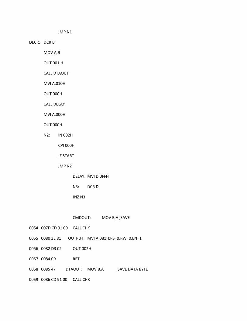
DECR: DCR B
MOV A,B
OUT 001 H
CALL DTAOUT
MVI A,010H
OUT 000H
CALL DELAY
MVI A,000H
OUT 000H
N2: IN 002H
CPI 000H
JZ START
JMP N2
DELAY: MVI D,0FFH
N3: DCR D
JNZ N3
CMDOUT: MOV B,A ;SAVE
0054 007D CD 91 00 CALL CHK
0055 0080 3E 81 OUTPUT: MVI A,081H;RS=0,RW=0,EN=1
0056 0082 D3 02 OUT 002H
0057 0084 C9 RET
0058 0085 47 DTAOUT: MOV B,A ;SAVE DATA BYTE
0059 0086 CD 91 00 CALL CHK

0060 0089 3E 03 MVI A,003H;RW=0,RS=1,E=1
0061 008B D3 02 OUT 002H
0062 008D 78 MOV A,B;RESTORE
0063 008E D3 01 OUT 001H
0064 0090 C9 RET
0065 0091 3E 92 CHK: MVI A,092H;SET B AS INPUT PORT
0066 0093 D3 03 OUT 003H
0067 0095 3E 85 READ: MVI A,085H;RS=0,RW=1,EN=1;ENABLE HIGH
0068 0097 D3 02 OUT 002H
0069 0099 DB 01 IN 001H;CHECK D7
0070 009B 07 RLC;CARRY
0071 009C 3E 84 MVI A,084H;RS=0,RW=1,EN=LOW
0072 009E D3 02 OUT 002H
0073 00A0 DA 95 00 JC READ ;LOOP TILL BUSY
0074 00A3 3E 81 MVI A,081H;RS=0,RW=0,EN=HIGH
0075 00A5 3E 90 MVI A,090H ;SET B AS OUTPUT
0076 00A7 D3 03 OUT 003H
0077 00A9 78 MOV A,B
0078 00AA D3 01 OUT 001H
0079 00AC C9 RET
.END

TESTING
1. SID- SOD test: As the switch at SID pin is pushed, LED at the SOD pin of 8085 should light
up.
When this did not work, we checked the code first of all. It was found to be correct. Next
we checked the polarity of the LED we had used. This also seemed to be a dead end as it
was soldered properly. We then noticed that the ROM had been placed in the inverted
position causing it to heat up and causing the failure of our program. We immediately
replaced the ROM and checked all the other IC’s after consulting with Gadre Sir and
found two pins to be floating with the address latch, this was attended to ASAP.
2. After the SID SOD LED’s were working we realized that the intensity wasn’t enough we immediately desoldered the resistances and replaced them with those of lower value.
3. The LCD was tested by writing a code which displays HELLO 8085. The test was initially unsuccessful. After replacing nearly every IC on the board, and testing around 4-5 different LCD codes, we realized that the folly was in our designing of the schematic. We were not able to change the contrast of the LCD and that was where we realized that we put the LCD pins on the schematic in inverting position.Then finally it worked.
4. Then we tried to run the code for the program but the buzzer did not seem to work at all.
We consulted Omkar to identify any errors in the code but there were none. We checked
the buzzer voltage with the multimeter and found out that the buzzer was not getting
ample amount of current. So we changed the resistance placed along with it, after this
the buzzer worked for a second or so there was a very high pitch noise then it stopped.
On our consultation with Omkar again we found that the buzzer was no more, we
shorted the resistance and replaced the buzzer and the same happened again.
5. At this point of time we were out of buzzers and could not do anything about it. Slight
changes in our code were made so that at least the proper functioning hardware can be
presented along with the name of our project being displayed over the LCD. However, the
logic even when being implemented in the code could only be verified if there was a
proper functioning buzzer.
FUTURE SCOPE OF IMPROVEMENT

We completed 70-80% of the project. The part which we could not complete dealt with the
buzzer. Also, our intention of implementing the counter via the code and the alarm on the counter
decrement could not be verified because of the faulty buzzer.
CONCLUSION
We concluded that with hard work and patience and dedication, a lot of things can be
achieved. It was for the second time that Professor D.V Gadre gave us the feeling of being
Electronics Engineer not just bookworms and that it can be challengingly interesting. Errors
open up new horizons of thought and also give us knowledge of various other devices
(oscilloscope, multimeter, etc.) used for checking and correcting them.
Problem solving capability also increases.
BLIOGRAPHY
1. Microprocessor architecture, programming, and application
with the 8085 by Ramesh Gaonkar
2. Datasheets www.nxp.com/documents/data_sheet/HEF4060B.pdf www.ti.com/lit/ds/symlink/ne555.pdf www.alldatasheet.com/datasheet-pdf/pdf/66100/INTEL/8255A.htmlwww.alldatasheet.com/datasheet-pdf/pdf/92530/INTEL/8085AH.htmlwww.nxp.com/documents/data_sheet/74HC_HCT573.pdf www.ti.com/lit/ds/symlink/sn74ls04.pdwww.ti.com/lit/ds/symlink/sn74ls32.pdfwww.ti.com/lit/ds/symlink/lm158-n.pdwww.ti.com/lit/ds/symlink/sn74ls138.pdf https://www.sparkfun.com/datasheets/LCD/ADM1602K-NSW-FBS-3.3v.pdfwww.agspecinfo.com/pdfs/J/JHD12864.PDF


![Single-head pumps...Wilo-Multivert MVI 50 Hz MVI 100 MVI 200 MVI 400 MVI 800 MVI 1600-6 S e r i es x p a n - s i o n ! H[m] 0 Q[m³/h] 0 20 40 60 80 100 120 140 160 180 200 220 20](https://img.dokumen.tips/doc/110x75/6090630f4b5f1b328e2b0736/single-head-wilo-multivert-mvi-50-hz-mvi-100-mvi-200-mvi-400-mvi-800-mvi-1600-6.jpg)