Embed Size (px)
Citation preview
1
Timing, Anew Technique for Determination the Machine
lectronic Shuttle Location and Shuttle Speed by Using E
Triggers
Dr: Hashim Ali Salem & Amel Sulieman Ahmed
Depart:Textile engineering college of engineering, Sudan University of
Science & Technology.
Shuttle ,Triggers, Loom, Timing ABSTRACT:
It is necessary to determine the start and the end of the machine cycle
of the loom, because it will facilitate the investigation of the behaviour of
the loom during the machine cycle[1].
An instrument was developed to determine the machine cycle
electronically. This instrument consisted of a light switch which could be
made of different shapes to fit the different parts of the loom where needed.
Two types of the light switch were made and used in this work, type (E) and
type (F). Both types were used in this work. Type (E) was used to determine
the start and the end of two machine cycled. Type (F) was used to determine
the shuttle locations during its flight through the warp shed and the shuttle
speed inside the shuttle box.
The results obtained showed and gave accurate and valuable
knowledge about machine timing and shuttle locations at any milli second
through the machine cycle.

2
:ا�����
���� ا������ � �ورةا��� ا���ورى � ��� ��ا�� و����� ���� ا�' &�% $ن ذ��! ���� ��آ���� ا�
��� اداء و �*�(�ت� .ا������ ���ا-��ء دور ��آ��� ا�
ه<ا ا�=��ز ;>�رة ;� �:'�ح 6718 .�' ��� دورة ا���آ��� ا��'�و��ً� �4 ا��3ء و���12 ��0ز
����@A��*� �:�'B� ل��D�� E� 47F'اء�G0ا �� �'6 �� �4 ا$I'��ج ا��@ (���ا��B'�:� ا���آ�
ا���1ع و (E) وه�� ا��1ع(6 ه<ا ا�A� اB'K�ا��� :'�ح ا��J71 و�4 �4 �*��E �1;�� �� ا��
(F) . 1ع� ���� @�ااB'�K� ��4 (F)ا���1ع . ��آ���� �� �������� دور�� و �' ��� ��ا�� @�ااB'K� �(E) 4ا�'�
��وق � ا���آ1ك�K; ا��ً� اB'K�م �' ���و 1�Mط ا���اءا���آ1ك ا-��ء ��Nا�@ FMل ا��آ�S Mدا
.ا���آ1ك
�'��7 ا�'6 �4 ا� *1ل ;���� أ��Wت و أ;��1�A� T2ت د�U&� و�U�� T�U1� �; ا���آ���� و ا�
.FMل دورة ا���آ���) ��G0)����- 6ء �� ا�Z �� ا�����Y أ��آ� ا���آ1ك ��ى اي
1.0 INTRODUCTION:
To assess the effects of any textile and mechanical parameters on a
weaving loom, a method to determine the timing of the machine cycle
should be introduced. Due to the high speed of the loom and the moving
parts of all the mechanisms of the loom, a new technique for measuring the
timing of the loom and the locations of the shuttle during its flight through
the shed and inside the shuttle boxes became essential. To determine the
exact speed of the shuttle inside the shuttle box was impossible[2] before
introducing this technique. Because of the fast speed of the shuttle, an
electronic trigger was developed in this work. Two types of the electronic
triggers were made in this work, type (E) and type (F) and both are described
below.

3
2.0 MATERIALS AND METHODS:
2-1 Electronic trigger type ( E ):
Figure (1.1) shows the light switch type E. The plate (D) was firmly
fixed to the bottom shaft of the picanol loom and so rotated with it. A slot
( C) was made on the plate (D) just wide enough to let the light pass through.
The bracket containing (A) and ( B) was fixed to the frame of the loom. ( A)
was a light source and ( B) a photoelectric cell. When the light passed from
(A) to ( B) through the slot ( C) , a switch activated by the photoelectric cell
was closed, triggering a signal to a channel[3] of an oscilloscope (channel B)
. The plate was fixed in such a position that the trigger was activated when
the machine was at front dead centre. Because plate (D) was mounted on the
bottom shaft, the switch operated only once each two machine cycles. The
other channel of the oscilloscope (channel A) could display any other
measurement of a textile parameter. When both channels were on both
measurements would be displayed on the screen.
Figure (1.1) light switch type (E)
2-2 Electronic trigger , type ( F ):
4
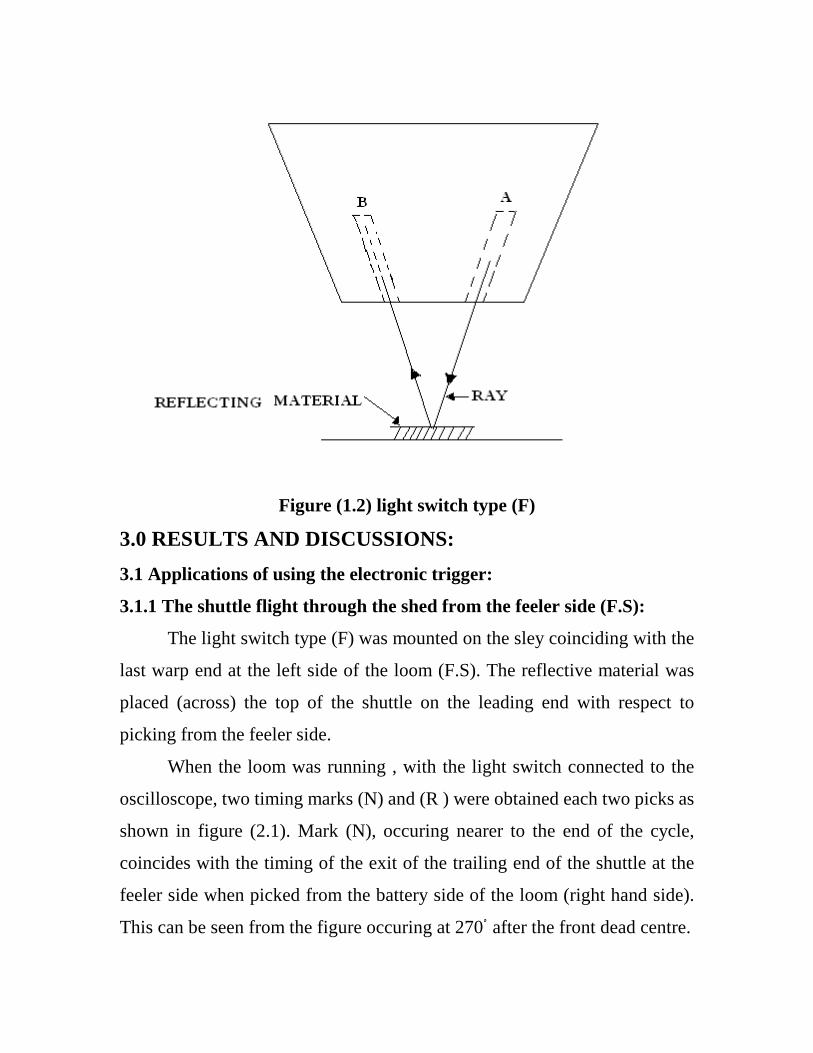
This configuration of the light switch is shown in figure (1.2). It
works on the principle of reflecting the light back to the switch to close the
circuit . The source of light came from the groove (A) and was detected at
(B) after being reflected via a reflective material mounted on a moving
part.The best distance between the switch and the reflecting material was
found to be (10) millimeters. If the light from (A) was reflected to (B), the
circuit of the switch would be closed[4] triggering a singal to the oscilloscope
(channel B). This type (F) was used as well to determine the machine cycle
of the loom. The swich containing (A and B) was mounted to the frame of
the loom and the reflecting material was placed on the rim of the wheel of
the crank shaft, so that when the light was reflected by the reflecting
material, the machine was at the front dead centre.
This type (F) proved very useful, because it was small in size and it
could be fitted easily into confined spaces on the loom. It was used to trigger
the shuttle when entering and leaving, the shed and shuttle boxes on both
sides of the picanol loom[5]. It was used also to determine the exact angle of
the start of picking.
5
Figure (1.2) light switch type (F)
3.0 RESULTS AND DISCUSSIONS:
3.1 Applications of using the electronic trigger:
3.1.1 The shuttle flight through the shed from the feeler side (F.S):
The light switch type (F) was mounted on the sley coinciding with the
last warp end at the left side of the loom (F.S). The reflective material was
placed (across) the top of the shuttle on the leading end with respect to
picking from the feeler side.
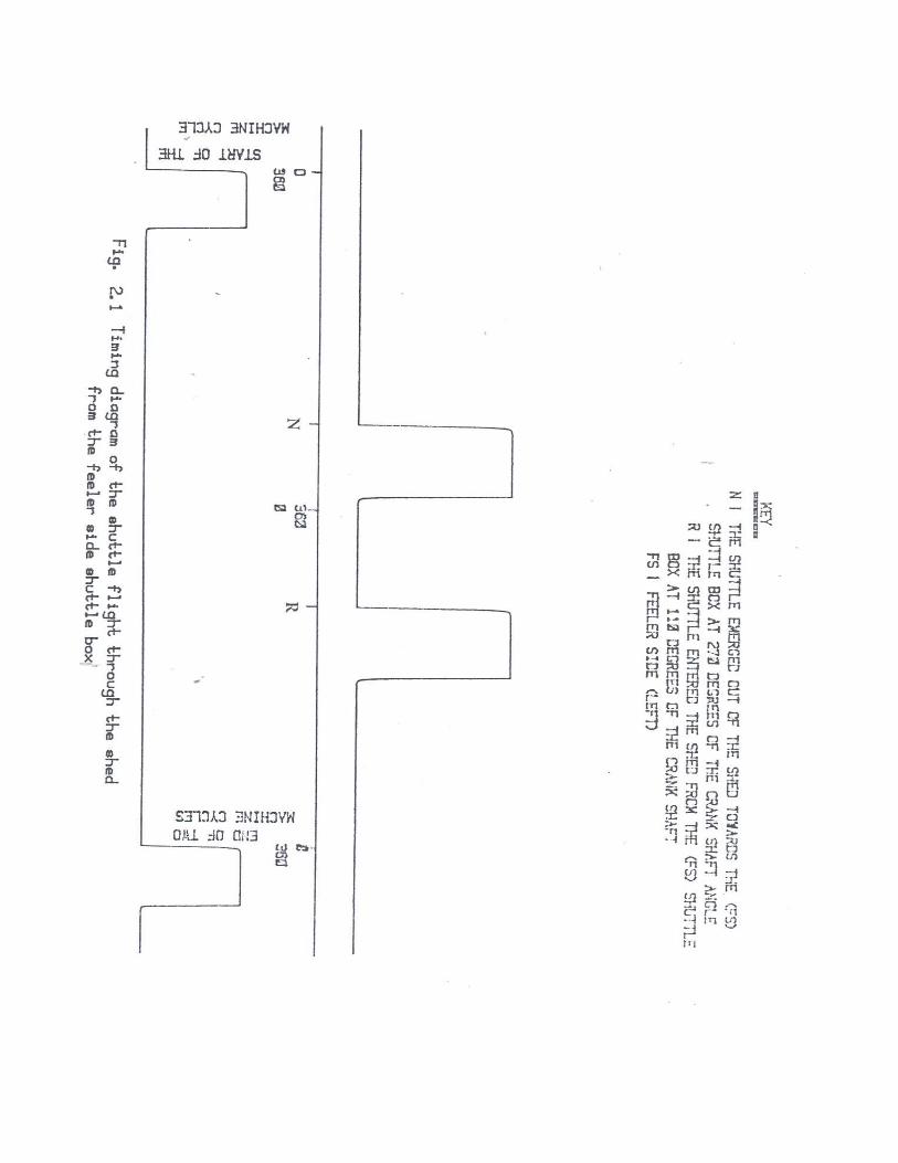
When the loom was running , with the light switch connected to the
oscilloscope, two timing marks (N) and (R ) were obtained each two picks as
shown in figure (2.1). Mark (N), occuring nearer to the end of the cycle,
coincides with the timing of the exit of the trailing end of the shuttle at the
feeler side when picked from the battery side of the loom (right hand side).
This can be seen from the figure occuring at 270 ْ after the front dead centre.
6

7
The mark (R) occuring nearer to the commencement of a cycle,
indicates the time at which the shuttle enters the shed when picked from the
feeler side. This can be seen to occur at 110 ْ of crank shaft rotation from
front dead centre. Clearly, by considering the time of entry of the shuttle into
the shed from one side of the loom and the time of its exit from the shed at
the same pick, the duration of the shuttle flight[6] in the shed could be
determined. The duration of the shuttle inside the shed for this loom is 160 ْ
of crank rotation (270 ْ- 110ْ ).
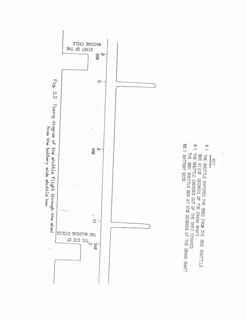
3.1.2 The shttle flight through the shed from the battery side (B.S):
Figure (2.2) shows the timing diagram of the shuttle flight through the
shed when picked from the battery side (right hand side). To achieve this
diagram, the light switch (type F) was mounted on the sley to coincide with
the last warp end towards the battery side of the loom. A 3mm wide strip of
reflective material was placed across the top of the shuttle on the leading end
with respect to picking from the battery side.The light switch was connected
to channel (A) of the oscilloscope. When the loom was running, two timing
marks (K and M) were obtained for each two picks. Mark (K), occuring
nearer to the commencement of a cycle, indicates the time at which the
shuttle enters the shed when picked from the battery side. Thiscan be seen
occuring at 110ْ of crank shaft rotation. Mark (M), coincides with the timing
of exit of the trailing end of the shuttle after being picked from the feeler
side. This can be seen to occur at 270 ْ after front dead centre.
8
9
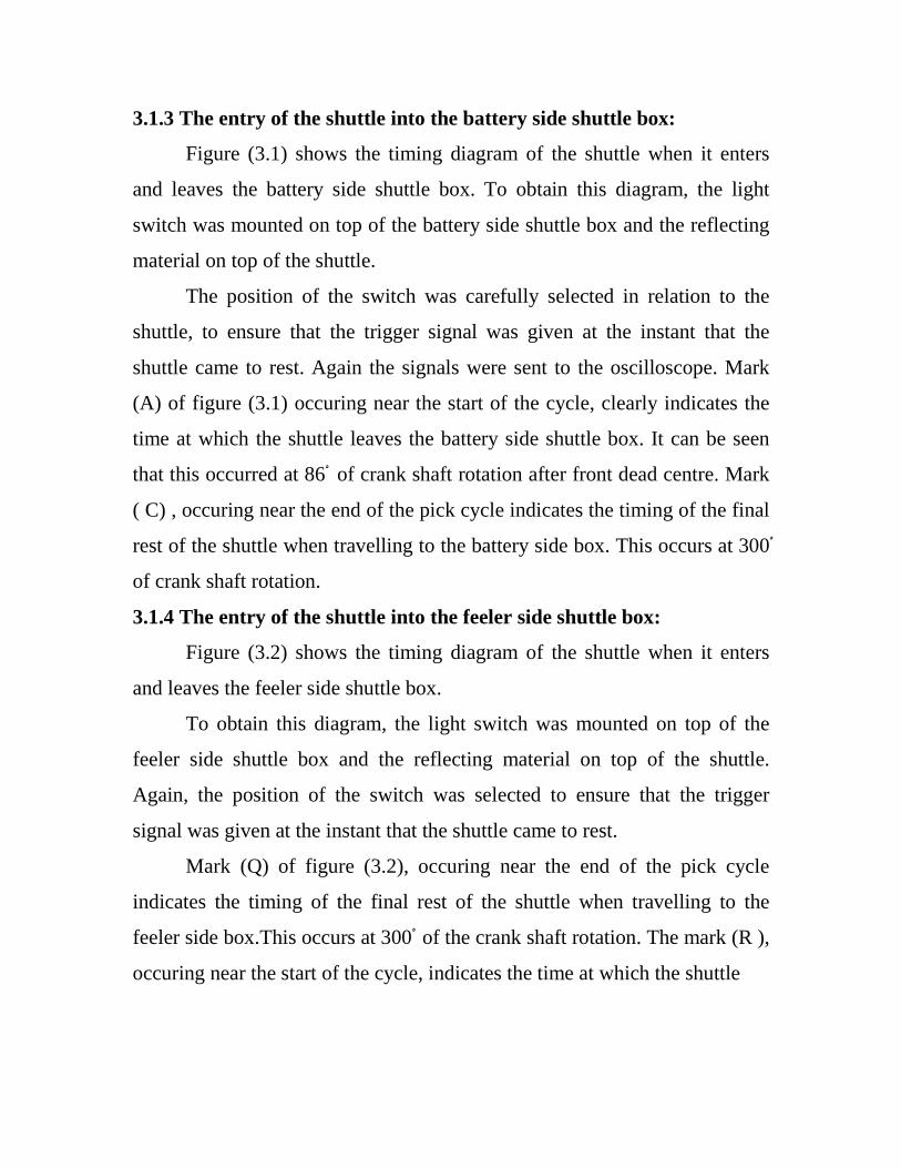
3.1.3 The entry of the shuttle into the battery side shuttle box:
Figure (3.1) shows the timing diagram of the shuttle when it enters
and leaves the battery side shuttle box. To obtain this diagram, the light
switch was mounted on top of the battery side shuttle box and the reflecting
material on top of the shuttle.
The position of the switch was carefully selected in relation to the
shuttle, to ensure that the trigger signal was given at the instant that the
shuttle came to rest. Again the signals were sent to the oscilloscope. Mark
(A) of figure (3.1) occuring near the start of the cycle, clearly indicates the
time at which the shuttle leaves the battery side shuttle box. It can be seen
that this occurred at 86 ْ of crank shaft rotation after front dead centre. Mark
( C) , occuring near the end of the pick cycle indicates the timing of the final
rest of the shuttle when travelling to the battery side box. This occurs at 300 ْ
of crank shaft rotation.
3.1.4 The entry of the shuttle into the feeler side shuttle box:
Figure (3.2) shows the timing diagram of the shuttle when it enters
and leaves the feeler side shuttle box.
To obtain this diagram, the light switch was mounted on top of the
feeler side shuttle box and the reflecting material on top of the shuttle.
Again, the position of the switch was selected to ensure that the trigger
signal was given at the instant that the shuttle came to rest.
Mark (Q) of figure (3.2), occuring near the end of the pick cycle
indicates the timing of the final rest of the shuttle when travelling to the
feeler side box.This occurs at 300 ْ of the crank shaft rotation. The mark (R ),
occuring near the start of the cycle, indicates the time at which the shuttle

10

11

12
leaves the feeler side shuttle box. It can be seen that this occured at 75 ْ of
crank shaft rotation after front dead centre.
3.1.5 Determination of the velocity of the shuttle inside the shuttle box:
It is a very hard task to determine the velocity of the shuttle inside the
shuttle box. The front and back walls of the shuttle box as well as the top
cover obstructed any trial for measuring the velocity of the shuttle inside the
shuttle box[7].
The new technique in this study by using the light switch made the
determination of the velocity of the shuttle inside the shuttle box possible.
The light switch was mounted and fixed on top of the shuttle box. Eleven
marks were made on top of the shuttle by using the reflecting material. The
space between each two marks allthrough the length of the shuttle was 3
centimeters. The time in milliseconds at the marks was recorded.
The velocity of the shuttle was calculated[8] using the recorded
displacements and times at the marks. Two speeds of the loom were used,
namely 161 and 170 revs/min. The data obtained when using the speed of
161 revs/min of the loom was recorded on table (1.A) and plotted in figure
(4.1). The data obtained when using the speed of 170 revs/min of the loom
was recorded on table (1.B) and plotted in figure (4.2).
13
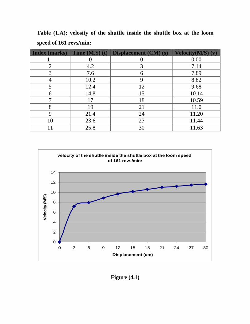
Table (1.A): velosity of the shuttle inside the shuttle box at the loom
speed of 161 revs/min:
Index (marks) Time (M.S) (t) Displacement (CM) (s) Velocity(M/S) (v) 1 0 0 0.00 2 4.2 3 7.14 3 7.6 6 7.89 4 10.2 9 8.82 5 12.4 12 9.68 6 14.8 15 10.14 7 17 18 10.59 8 19 21 11.0 9 21.4 24 11.20 10 23.6 27 11.44 11 25.8 30 11.63
velocity of the shuttle inside the shuttle box at the loom speed of 161 revs/min:
0
2
4
6
8
10
12
14
0 3 6 9 12 15 18 21 24 27 30
Displacement (cm)
Vel
oci
ty (M
/S)
Figure (4.1)
14
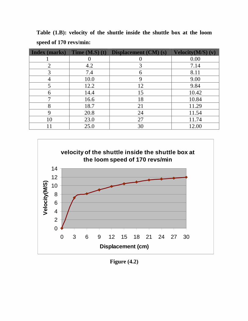
Table (1.B): velocity of the shuttle inside the shuttle box at the loom
speed of 170 revs/min:
Index (marks) Time (M.S) (t) Displacement (CM) (s) Velocity(M/S) (v) 1 0 0 0.00 2 4.2 3 7.14 3 7.4 6 8.11 4 10.0 9 9.00 5 12.2 12 9.84 6 14.4 15 10.42 7 16.6 18 10.84 8 18.7 21 11.29 9 20.8 24 11.54 10 23.0 27 11.74 11 25.0 30 12.00
velocity of the shuttle inside the shuttle box at the loom speed of 170 revs/min
0
2
4
6
8
10
12
14
0 3 6 9 12 15 18 21 24 27 30
Displacement (cm)
Vel
ocity
(M/S
)
Figure (4.2)
15
4.0 CONCLUSIONS:
A new technique has been developed in this work by using electronic
triggers for the determination of the timing of the introduced in this work
weaving machine. Two types of triggers (type (E) and type (F)) were and
both are applied to the weaving machine. The exact angles of the shuttle
locations during its flight inside the warp shed is determined. The angles of
entering and of leaving both shuttle boxes are determined precisely. This
technique made it possible to determine the velocity of the shuttle inside the
shuttle box, in a very simple and an accurate way. This light switch could be
made in various and small shapes to fit any confined space in the loom.
5.0 REFERENCES:
[1] Holocombe,B.(1974),Application of Radio Telemetry Tcchniques to the
measurement of dynamic warp & weft tension during the weaving
cycle,Ph.d thesis, School of Textile Tech, University of new south wales,
Australia.
[2] Lord, P.R.,& Mohamad, M.H.(1975), An analysis of the picking
mechanism of a textile loom, Journal of Engineering for industry, may 1975.
[3] Nicolet Digital Oscilloscope 's (3091) operating manual, Niclet
instrument corporation, Oscilloscope division, Madison, Wisconsion, U.S.A.
[4] Fitzgerald, A.E.,and Higginbotham, D.E.(1957)."Basic Electrical
Engineering", Second edition.Mc Graw-HILL Book companylnc.
[5] Picanol "President 4C" operating manual, Ypres (Belgium).
[6] Vincent, J.J (1939), The mathematical Theorey of shuttle projection.
Journal of the Textile institute, Vol. 30.

16
[7] Gorshkov. A.V.(1956). The effect of tuning the picking motion on the
operating conditions of the loom motor.Tech. of textile industry U.S.S.R.,
No.3.
[8] Thomas Bevan (1964), The theory of machines. Longmans, Green & Co
LTD, London W.l (BRITAIN).