Embed Size (px)
Citation preview

Project Manual
Andrew Robinson-14 Chilled & Hot Water Reroute, Lighting and Parking
Improvements
100% CONSTRUCTION DOCUMENTS
AEI PROJECT NO.: 12730-02
DATE: March 1st, 2013
PREPARED BY:
AFFILIATED ENGINEERS SE, INC. 3007 SW WILLISTON ROAD
GAINESVILLE, FL 32608 Phone: 352/376-5500
Fax: 352/375-3479


Andrew Robinson-14 Chilled & Hot Water Project No. 12730-02 Reroute, Lighting and Parking Improvements Sign and Seal Page 100% Construction Documents 03/01/2013
CONTRACTING REQUIREMENTS
SEAL CERTIFICATION
PREPARED BY MECHANICAL ENGINEERING: SEAL BY: ___________________________________ Jack S. Neale, P.E. FL. P.E. No. 42678 ELECTRICAL ENGINEERING: SEAL BY: ___________________________________ Vinod K. Trehan, P.E. FL. P.E. No. 72349
END OF LISTING

THIS PAGE INTENTIONALLY BLANK
Andrew Robinson-14 Chilled & Hot Water Project No. 12730-02 Reroute, Lighting and Parking Improvements Table of Contents 100% Construction Documents TOC - 1 03/01/2013
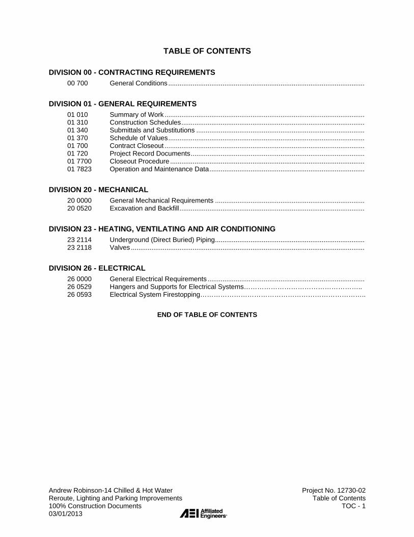
TABLE OF CONTENTS
DIVISION 00 - CONTRACTING REQUIREMENTS
00 700 General Conditions .........................................................................................................
DIVISION 01 - GENERAL REQUIREMENTS
01 010 Summary of Work ........................................................................................................... 01 310 Construction Schedules .................................................................................................. 01 340 Submittals and Substitutions .......................................................................................... 01 370 Schedule of Values ......................................................................................................... 01 700 Contract Closeout ........................................................................................................... 01 720 Project Record Documents ............................................................................................. 01 7700 Closeout Procedure ........................................................................................................ 01 7823 Operation and Maintenance Data ...................................................................................
DIVISION 20 - MECHANICAL
20 0000 General Mechanical Requirements ................................................................................ 20 0520 Excavation and Backfill ...................................................................................................
DIVISION 23 - HEATING, VENTILATING AND AIR CONDITIONING
23 2114 Underground (Direct Buried) Piping ................................................................................ 23 2118 Valves .............................................................................................................................
DIVISION 26 - ELECTRICAL
26 0000 General Electrical Requirements .................................................................................... 26 0529 Hangers and Supports for Electrical Systems…………………………………………….. 26 0593 Electrical System Firestopping………………………………………………………………..
END OF TABLE OF CONTENTS

THIS PAGE INTENTIONALLY BLANK

Section 00700, Page 1 of 1
SECTION 00700 - GENERAL CONDITIONS
PART 1 - GENERAL 1.1 RELATED SECTIONS:
Documents affecting work of this Section include, but are not necessarily limited to other Sections in Division 1 of these Specifications.
1.2 DESCRIPTION:
In the performance of the Work described within these Contract Documents, the Contractor shall comply with, be guided by, and follow AIA Document A201, "The General Conditions of the Contract for Construction", 1987 Edition as revised on October 16, 1989 by the Office of Capital Programs, Florida Board of Regents for its use in connection with the Construction Program for the State University System of Florida, Articles 1 through 14 inclusive, except as eliminated or modified in the Supplementary Conditions.
1.3 REFERENCE: Refer to UNF General Counsel website for the following:
AIA 101 - 2007 Customized by GC. AIA 201 - 2007 General Conditions. AIA 201 - 2007 Supplemental Conditions, dated November 28, 2012
END OF SECTION

Section 01010, 1 of 1
SECTION 01010 - SUMMARY OF THE WORK
PART 1 - GENERAL 1.1 RELATED SECTIONS:
Documents affecting the work of this Section include, but are not necessarily limited to, the General Conditions, the Supplementary Conditions, and other Sections in Division 1 of these Specifications.
1.2 DESCRIPTION OF WORK INCLUDED:
The work includes: Re-route chilled water and heating hot water piping around building 14 B and D. Demolition of existing parking lot #9 lights, and providing new lighting scheme. Resurfacing of parking lot #9.
END OF SECTION

Section 01310, Page 1 of 4
SECTION 01310 - CONSTRUCTION SCHEDULES
PART 1 - GENERAL 1.1 RELATED SECTIONS:
A. Documents affecting the work of this Section include, but are not necessarily limited to, the General Conditions, the Supplementary Conditions, and other Sections in Division 1 of these Specifications.
1.2 DESCRIPTION:
A. WORK INCLUDED:
To assure adequate planning and execution of the Work so that the Work is completed within the number of calendar days allowed in the Contract, and to assist the Engineer in appraising the reasonableness of the proposed schedule and in evaluating progress of the Work, prepare and maintain the schedules and reports described in this Section.
B. RELATED WORK:
1. Requirements for Progress Schedule: General Conditions (Section 00700).
2. Construction Period: As per Contract.
C. DEFINITIONS:
"Day", as used throughout the Contract unless otherwise stated, means "calendar day".
1.3 QUALITY ASSURANCE:
A. Employ, if necessary, a scheduler who is thoroughly trained and experienced in compiling construction schedule date, and in preparing and issuing periodic reports as required below.
B. Perform data preparation, analysis, charting, and updating in accordance with
standards approved by the Engineer.

Section 01310, Page 2 of 4
C. Reliance upon the approved schedule:
1. The construction schedule as approved by the Engineer will be an integral part of the Contract and will establish interim completion dates for the various activities under the Contract.
2. Should any activity not be completed within 15 days after the stated
schedule date, the Owner shall have the right to require the Contractor to expedite completion of the activity by whatever means the Owner deems appropriate and necessary, without additional compensation to the Contractor.
3. Should any activity be 30 days or more behind schedule, the Owner shall
have the right to perform the activity or have the activity performed by whatever method the Owner deems appropriate.
4. Costs incurred by the Owner and by the Engineer in connection with
expediting construction activity under this Article shall be reimbursed by the Contractor.
5. It is expressly understood and agreed that failure by the Owner to
exercise the option either to order the Contractor to expedite an activity or to expedite the activity by other means shall not be considered to set a precedent for any other activities.
1.4 SUBMITTALS:
A. Comply with pertinent provisions of Section 01340, Submittals and Substitutions.
B. CONSTRUCTION SCHEDULE:
Within ten (10) calendar days after the Contractor has received the Owners' Notice to Proceed, submit one (1) reproducible copy and four (4) prints of a construction schedule prepared in accordance with Part 3 of this Section.
C. PERIODIC REPORTS:
After the above-mentioned construction schedule is approved, if the UNF Project Manager deems it to be necessary, the Contractor will be required to submit periodic updates of the construction schedule consisting of four (4) prints of the construction schedule updated as described in Part 3 of this Section.

Section 01310, Page 3 of 4
PART 2 - PRODUCTS 2.1 CONSTRUCTION ANALYSIS:
A. Graphically show by bar chart the order and interdependence of all activities necessary to complete the Work, and the sequence in which each activity is to be accomplished, as planned by the Contractor and his project field superintendent in coordination with all subcontractors whose work is shown on the diagram.
B. Include, but do not necessarily limit indicated activities to:
1. Project mobilization; 2. Submittal and approval of Shop Drawings and Samples; 3. Procurement of equipment and critical materials; 4. Fabrication of special material and equipment, and its installation and
testing; 5. Final cleanup; 6. Final inspecting and testing; 7. All activities by the Engineer that affect progress, required dates for
completion, or both, for all and each part of the Work. PART 3 - EXECUTION 3.1 CONSTRUCTION SCHEDULE:
A. As soon as practical after receipt of Notice to Proceed, complete the construction analysis in preliminary form, meet with the Engineer, review contents of the proposed construction schedule, and make all revisions agreed upon. Contractor will coordinate his work with the UNF Schedule. Construction work will be so scheduled and carried out that the normal operations of the College must be given first priority. This applies particularly to outages of Utilities and restriction of access. Such construction operations must be carried out outside of normal working hours and by overtime, weekend, and holiday working. It shall be the contractor's responsibility to provide for this in his Bid.
B. Submit in accordance with Paragraph 1.4 above.

Section 01310, Page 4 of 4
3.2 PERIODIC REPORTS:
As required under Paragraph 1.4 above, update the approved construction schedule. A. Indicate "actual" progress in percent completion for each activity; B. Provide written narrative summary of revisions causing delay in the program,
and an explanation of corrective actions taken or proposed.
3.3 REVISIONS:
Make only those revisions to approved construction schedule as are approved in advance by the Engineer.
END OF SECTION

Section 01340, Page 1 of 5
SECTION 01340 - SUBMITTALS AND SUBSTITUTIONS
PART 1 - GENERAL 1.1 RELATED SECTIONS:
A. Documents affecting the work of this Section include, but are not necessarily limited to, the General Conditions, the Supplementary Conditions, and other Sections in Division 1 of these Specifications.
B. Individual requirements for submittals also may be described in pertinent
Sections of these Specifications.
1.2 DESCRIPTION OF WORK:
A. WORK INCLUDED:
Make submittals required by the Contract Documents, and revise and resubmit as necessary to establish compliance with the specified requirements.
B. WORK NOT INCLUDED:
1. Un-required submittals will not be reviewed by the Engineer. 2. The Contractor may require his subcontractors to provide drawings,
setting diagrams, and similar information to help coordinate the Work, but such data shall remain between the Contractor and his Subcontractors and will not be reviewed by the Engineer.
1.3 QUALITY ASSURANCE:
A. COORDINATION OF SUBMITTALS:
1. Prior to each submittal, carefully review and coordinate all aspects of each item being submitted.
2. Verify that each item and the submittal for it conform in all respects with
the specified requirements. 3. By affixing the Contractor's signature to each submittal, certify that this
coordination has been performed.

Section 01340, Page 2 of 5
B. SUBSTITUTIONS:
1. The Contract is based on the standards of quality established in the Contract Documents. Substitutions will be considered only when listed at the time of bidding. If bids are based on equivalent products, indicate on the Bid Proposal Form the manufacturer's name and catalog number. Bidder shall submit, at the time of bidding, cut sheets, sketches, and descriptive literature, and/or complete specifications. The Bidder shall also explain in detail the reason why the proposed equivalent will meet the specifications and not be considered an exception thereto.
2. The following products do not require further approval except for interface
within the Work.
a. Products specified by reference to standard specifications such as ASTM and similar standards.
b. Products specified by manufacturer's name and catalog model
number.
3. Do not substitute materials, equipment, or methods unless such substitution has been specifically approved in writing for this work by the Engineer.
C. "OR EQUAL",
1. Where the phrase "or equal", or "or equal as approved by the Engineer", occurs in the Contract Documents, do not assume that the materials, equipment, or methods will be approved as equal unless the item has been specifically so approved for this Work by the Engineer.
2. The decision of the Engineer shall be final.
1.4 SUBMITTALS:
Make submittals of Shop Drawings, Samples, substitution requests, and other items in accordance with the provisions of this Section.

Section 01340, Page 3 of 5
PART 2 - PRODUCTS 2.1 SHOP DRAWINGS:
A. SCALE AND MEASUREMENTS:
Make Shop Drawings accurately to a scale sufficiently large to show all pertinent aspects of the item and its method of connection to the work.
B. TYPES OF PRINTS REQUIRED:
Submit Shop Drawings in the form of one sepia transparency of each sheet plus three blueline or blackline prints of each sheet.
C. Review comments of the Engineer will be shown on the sepia transparency when it is returned to the Contractor. The Contractor may make and distribute such copies as are required for his purposes.
2.2 MANUFACTURER'S LITERATURE:
A. Where contents of submitted literature from manufacturers includes data not pertinent to the submittal, clearly show which portions of the contents are being submitted for review.
B. Submit 4 copies. One copy will be retained by the Engineer.
PART 3 - EXECUTION 3.1 IDENTIFICATION OF SUBMITTALS:
A. Consecutively number all submittals.
1. When material is resubmitted for any reason, transmit under a new letter of transmittal and with a new transmittal number.
2. On resubmittals, cite the original submittal number for reference.
B. Accompany each submittal with a letter of transmittal showing all information required for identification and checking.
C. On at least the first page of each submittal, and elsewhere as required for
positive identification, show the submittal number in which the item was included. D. Maintain an accurate submittal log for the duration of the Work, showing current
status of all submittals at all times. Make the submittal log available to the

Section 01340, Page 4 of 5
Engineer for his review upon request.
3.2 GROUPING OF SUBMITTALS:
Unless otherwise specified, make submittals in groups containing all associated items to assure that information is available for checking each item when it is received. A. Partial submittals may be rejected as not complying with the provisions of the
Contract. B. The Contractor may be held liable for delays caused by non-complying
submittals.
3.3 TIMING OF SUBMITTALS:
A. Make submittals far enough in advance of scheduled dates for installation to provide time required for reviews, for securing necessary approvals, for possible revisions and re-submittals, and for placing orders and securing delivery.
B. In scheduling, allow at least ten working days for review by the Engineer
following his receipt of the submittal.
3.4 ENGINEER'S REVIEW:
A. Review by the Engineer does not relieve the Contractor from responsibility for errors that may exist in the submitted data.
B. SHOP DRAWINGS:
Shop Drawings submitted to the Engineer for approval shall first be checked and approved by the Contractor, the evidence of which shall be a "checked" stamp marked "Approved", or "Approved as Noted", on each copy of each Shop Drawing, placed thereon by the Contractor. Shop Drawings received without the Contractor's "checked" stamp will be cause for immediate return without further action. Each drawing correctly submitted will be checked by the Architect/Engineer and marked "Approved", "Approved as Noted", or "Not Approved".

Section 01340, Page 5 of 5
C. REVISIONS:
1. The Contractor shall make the revisions required by the Engineer. 2. If the Contractor considers any required revision to be a change, he shall
so notify the Engineer as provided for in the General Conditions. 3. The Contractor shall make only those revisions as directed or approved
by the Engineer.
END OF SECTION

Section 01370, Page 1 of 1
SECTION 01370 - SCHEDULE OF VALUES
PART 1 - GENERAL 1.1 RELATED SECTIONS:
A. Documents affecting work of this Section include, but are not necessarily limited to, General Conditions, Supplementary Conditions, and Sections in Division 1 of these Specifications.
B. The Schedule of Values is per AIA 201 – 2007 Supplemental Conditions dated
November 28th, 2012 (Refer to UNF General Counsel’s website).
1.2 DESCRIPTION OF WORK INCLUDED:
A. Provide a detailed breakdown of the agreed Contract Sum showing values allocated to each of the various parts of the Work, as specified herein and in other provisions of the Contract Documents.
B. The breakdown of the Work shall be made according to the format of the
Construction Specifications Institute's "Master List of Titles and Numbers for the Construction Industry" (1988 Edition).
1.3 QUALITY ASSURANCE:
A. Use required means to assure arithmetical accuracy of the sums described. B. When so required by the Engineer, provide copies of the subcontracts or other
data acceptable to the Engineer, substantiating the sums described. 1.4 SUBMITTALS:
Within ten (10) days after receipt of Notice to Proceed, the Contractor shall submit a proposed Schedule of Values to the Engineer.
A. Meet with the Engineer and determine additional data, if any, required to be
submitted. B. Secure the Engineer's approval of the Schedule of Values prior to submitting first
application for payment. C. Submit Schedule of Values with each pay request indicating the percentage of
work completed.
END OF SECTION

Section 01700, Page 1 of 3
SECTION 01700 - CONTRACT CLOSEOUT
PART 1 - GENERAL 1.1 RELATED SECTIONS:
A. Documents affecting the work of this Section include, but are not necessarily limited to, the General Conditions, the Supplementary Conditions, and other Sections in Division 1 of these Specifications.
1.2 DESCRIPTION OF WORK INCLUDED:
Provide an orderly and efficient transfer of the completed Work to the Owner.
1.3 QUALITY ASSURANCE:
Prior to requesting inspection by the Engineer, use adequate means to assure that the Work is completed in accordance with the specified requirements and is ready for the requested inspection.
1.4 PROCEDURES:
A. SUBSTANTIAL COMPLETION:
1. The Contractor shall prepare and submit the list of items to be completed or corrected.
2. Within a reasonable time after receipt of the list, the Engineer will
inspect to determine status of completion.
3. Should the Engineer determine that the Work is not Substantially Complete:
a. The Engineer promptly will so notify the Contractor, in writing,
giving the reasons therefore. b. Remedy the deficiencies and notify the Engineer when ready
for reinspection. c. The Engineer will reinspect the Work.
4. When the Engineer concurs that the Work is Substantially Complete:
a. The Engineer will prepare a "Certificate of Substantial Completion" and a list of the Contractor's items to be completed or corrected.

Section 01700, Page 2 of 3
b. The Engineer will submit the Certificate to the Contractor and
then to the Owner for their written acceptance of the responsibilities assigned to them in the Certificate.
5. On those projects, which require maintenance and operating
manuals, such manuals shall be given to the Project Manager for distribution to relevant Physical Plant employees in advance of the Substantial Completion Inspection so those employees can familiarize themselves with the manuals in advance of the Substantial Completion Inspection.
B. FINAL COMPLETION:
1. Prepare and submit the notice. 2. Verify that the Work is complete. 3. Certify that:
a. Contract documents have been reviewed; b. Work has been inspected for compliance with the Contract
Documents; c. Work has been completed in accordance with the Contract
Documents;
d. Equipment and systems have been tested as required, and are operational;
e. Work is completed and ready for final inspection.
4. The Engineer will make an inspection to verify status of completion. 5. Should the Engineer determine that the Work is incomplete or
defective:
a. The Engineer promptly will so notify the Contractor, in writing, listing the incomplete or defective work.
b. Remedy the deficiencies promptly, and notify the Engineer when ready for re-inspection.
6. When the Engineer determines that the Work is acceptable under the Contract Documents, he will request the Contractor to make closeout submittals for which he is responsible.
C. CLOSEOUT SUBMITTALS:
1. By Contractor:
a. Three sets Operation and Maintenance Manuals as per Section 01730 (more sets may be requested; see Technical

Section 01700, Page 3 of 3
Specifications) b. Warranties and bonds; c. Keys and keying schedule;
d. Spare parts and materials extra stock; e. Evidence of compliance with requirements of governmental
agencies having jurisdiction; f. Evidence of payment and release of liens by subcontractors
and material suppliers; g. List of subcontractors, service organizations, and principal
vendors, including names, addresses, and telephone numbers where they can be reached for emergency service at all times, including nights, weekends, and holidays;
h. Shop Drawings.
D. FINAL ADJUSTMENT OF ACCOUNTS:
1. Submit a final statement of accounting to the Engineer, showing all adjustments to the Contract Sum.
2. If so required, the Engineer will prepare a final Change Order showing
adjustments to the Contract Sum, which were not made previously by Change Orders.
1.5 INSTRUCTION:
Instruct the Owner's personnel in proper operation and maintenance of systems, equipment, and similar items which are provided as part of the Work.

Section 01720, Page 1 of 5
SECTION 01720 - PROJECT RECORD DOCUMENTS
PART 1 - GENERAL 1.1 RELATED SECTIONS:
A. Documents affecting the work of this Section include, but are not necessarily limited to, the General Conditions, the Supplementary Conditions, and other Sections in Division 1 of these Specifications.
B. Other requirements affecting Project Record Documents may appear in
pertinent other Sections of these Specifications.
1.2 DESCRIPTION OF WORK INCLUDED:
A. Throughout progress of the work, maintain an accurate record of changes in the Contract Documents, as described in Paragraph 3.1 below.
B. Upon completion of the Work, submit the recorded changes to the Engineer as
described in Paragraphs 2.1.B and 3.2.B below.
1.3 QUALITY ASSURANCE:
A. Delegate the responsibility for maintenance of Record Documents to one person on the Contractor's staff as approved by the Engineer.
B. ACCURACY OF RECORDS:
1. Thoroughly coordinate changes within the Record Documents, making adequate and proper entries on each page of Specifications and each sheet of Drawings and other Documents where such entry is required to show the change properly.
2. Accuracy of records shall be such that future search for items shown in
the Contract Documents may rely reasonably on information obtained from the approved Project Record Documents.
C. Make entries within 24 hours after receipt of information that the change has
occurred.

Section 01720, Page 2 of 5
1.4 SUBMITTALS:
A. Comply with pertinent provisions of Section 01340. B. Prior to submitting each request for progress payment, secure the Engineer's
approval of the current status of the Project Record Documents as that approval may be a prerequisite for the Engineer to approve requests for progress payments and the request for Final Payment under the Contract.
C. Prior to submitting request for final payment, submit the job set of the Project
Record Documents to the Engineer and secure his approval.
1.5 PRODUCT HANDLING:
A. Maintain the job set of the Record Documents completely protected from deterioration and from loss and damage until completion of the Work and submittal of the job set to the Engineer for his transfer of all recorded data to the final Project Record Documents.
B. In the event of loss of recorded data, use means necessary to again secure the
data to the Engineer's approval.
1. Such means shall include, if necessary in the opinion of the Engineer, removal and replacement of concealing materials.
2. In such case, provide replacements to the standards originally required
by the Contract Documents.
PART 2 - PRODUCTS 2.1 RECORD DOCUMENTS:
A. JOB SET:
Promptly following receipt of the Owner's Notice to Proceed, secure from UNF, a Compact Disc with electronic files for job set.

Section 01720, Page 3 of 5
B. FINAL RECORD DOCUMENTS:
At the completion of the Work, the Contractor shall submit the job set of the Record Documents to the Engineer for review and approval. The Engineer is responsible to transfer all recorded data from the job set to the final Project Record Documents and to submit these documents to the Project Manager. Record documents shall indicate the "as-built" condition. Intermediate design representations not indicating the "as-built" condition shall be deleted from the Contract drawings by the Engineer.
PART 3 - EXECUTION 3.1 MAINTENANCE OF JOB SET::
A. Immediately upon receipt of the job set described in Paragraph 2.1.A above, identify each of the Documents with the title, "RECORD DOCUMENTS - JOB SET".
B. PRESERVATION:
1. Considering the Contract completion time, the probable number of occasions upon which the job set must be taken out for new entries and for examination, and the conditions under which these activities will be performed, devise a suitable method for protecting the job set to the approval of the Engineer.
2. Do not use the job set for any purpose except entry of new data and for
review by the Engineer. 3. Maintain the job set at the site of work as that site is designated by the
Engineer.
C. MAKING ENTRIES ON DRAWINGS:
1. Using an erasable colored pencil (not ink or indelible pencil), clearly describe the change by graphic line and note as required. Clearly indicate at each affected detail and other Drawing a full description of changes made during construction, and the actual location of items described in Paragraph 3.1.E.1 below.

Section 01720, Page 4 of 5
2. Date all entries. 3. Call attention to the entry by a "cloud" drawn around the area or areas
affected. 4. In the event of overlapping changes, use different colors for the
overlapping changes.
D. MAKING ENTRIES ON THE OTHER PERTINENT DOCUMENTS:
Make entries in the pertinent other Documents as approved by the Architect/Engineer.
E. CONVERSION OF SCHEMATIC LAYOUTS:
1. In some cases on the Drawings, arrangements of conduits, circuits, piping, ducts, and similar items, are shown schematically and are not intended to portray precise physical layout.
a. Final physical arrangement is determined by the Contractor,
subject to the Engineer's approval. b. However, design of future modifications of the facility may require
accurate information as to the final physical layout of items which are shown only schematically on the drawings.
2. Show on the job set of Record Drawings, by dimensions accurate to
within one inch, the centerline of each run of items such as are described in Paragraph 3.1.E.1.
a. Clearly identify the item by accurate notes such as "cast iron
drain", "galv. water", and the like. b. Show, by symbol or note, the vertical location of the item ("under
slab", "in ceiling plenum", "exposed", and the like). c. Make all identification sufficiently descriptive that it may be related
reliably to the Specifications.
3.2 FINAL PROJECT RECORD DOCUMENTS:
A. The purpose of the final Project Record Documents is to provide factual information regarding all aspects of the work, both concealed and visible, to enable future modification of the work to proceed without lengthy and expensive site measurement, investigation, and examination.

Section 01720, Page 5 of 5
B. APPROVAL OF RECORDED DATA:
1. At the completion of the Work, submit the completed job set of the Project Record Documents to the Engineer for review.
2. Participate in review meetings and promptly provide any additional
information requested and/or make revisions to the job set as required to obtain the Engineer's approval of the job set as accurate and complete.
3.3 CHANGES SUBSEQUENT TO ACCEPTANCE:
The Contractor has no responsibility for recording changes in the work subsequent to Final Completion, except for changes resulting from work performed under Warranty.
END OF SECTION

University of North Florida
Design Guidelines and Standards
01 77 00 Closeout Procedures
Page 36 of 330 Revised: 12/16/2010
01 77 00 Closeout Procedures
1. General
A. Related Documents: Drawings and general provisions of the contract, including General and Supplementary Conditions and other Division 1 Specification Sections, apply to this section.
B. Summary:
● This section includes administrative and procedural requirements for contract closeout, including, but not limited to, the following:
○ Inspection procedures.
○ Project Record Documents.
○ Operation and maintenance manuals.
○ Warranties.
○ Instruction of Owner’s personnel.
○ Final cleaning.
● Related sections include the following:
○ Divisions 2 through 16 sections for specific closeout and special cleaning requirements for products of those sections.
C. Substantial Completion:
● Preliminary Procedures: Before requesting inspection for determining date of Substantial Completion, complete the following. List items below that are incomplete in request.
○ Prepare a list of items to be completed and corrected (punch list), the value of items on the list, and reasons why the work is not complete.
○ Advise Owner of pending insurance changeover requirements.
○ Submit specific warranties, workmanship bonds, maintenance service agreements, final certifications, and similar documents.
○ Obtain and submit releases permitting Owner unrestricted use of the work and access to services and utilities. Include occupancy permits, operating certificates, and similar releases.

University of North Florida
Design Guidelines and Standards
01 77 00 Closeout Procedures
Page 37 of 330 Revised: 12/16/2010
○ Prepare and submit Project Record Documents, operation and maintenance manuals, Final Completion construction photographs and photographic negatives, damage or settlement surveys, property surveys, and similar final record information.
○ Deliver tools, spare parts, extra materials, and similar items to location designated by Owner. Label with manufacturer’s name and model number where applicable.
○ Make final changeover of permanent locks and deliver keys to Owner. Advise Owner’s personnel of changeover in security provisions.
○ Complete startup testing of systems.
○ Submit test/adjust/balance records.
○ Terminate and remove temporary facilities from project site, along with mockups, construction tools, and similar elements.
○ Advise Owner of changeover in heat and other utilities.
○ Submit changeover information related to Owner’s occupancy, use, operation, and maintenance.
○ Complete final cleaning requirements, including touchup painting.
○ Touch up and otherwise repair and restore marred exposed finishes to eliminate visual defects.
● Inspection: Submit a written request for inspection for Substantial Completion. On receipt of request, Architect will either proceed with inspection or notify contractor of unfulfilled requirements. Architect will prepare the Certificate of Substantial Completion after inspection or will notify contractor of items, either on contractor’s list or additional items identified by architect, that must be completed or corrected before certificate will be issued.
○ Reinspection: Request reinspection when the work identified in previous inspections as incomplete is completed or corrected.
○ Results of completed inspection will form the basis of requirements for Final Completion.
D. Final Completion:
● Preliminary Procedures: Before requesting final inspection for determining date of Final Completion, complete the following:

University of North Florida
Design Guidelines and Standards
01 77 00 Closeout Procedures
Page 38 of 330 Revised: 12/16/2010
○ Submit a final Application for Payment according to Division 1 section “Payment Procedures.”
○ Submit certified copy of Architect’s Substantial Completion inspection list of items to be completed or corrected (punch list), endorsed and dated by Architect. The certified copy of the list shall state that each item has been completed or otherwise resolved for acceptance.
○ Submit evidence of final, continuing insurance coverage complying with insurance requirements.
○ Instruct Owner’s personnel in operation, adjustment, and maintenance of products, equipment and systems.
● Inspection: Submit a written request for final inspection for acceptance. On receipt of request, architect will either proceed with inspection or notify contractor of unfulfilled requirements. Architect will prepare a final Certificate for Payment after inspection or will notify contractor of construction that must be completed or corrected before certificate will be issued.
○ Reinspection: Request reinspection when the work identified in previous inspections as incomplete is completed or corrected.
E. List of Incomplete Items (Punch List)
● Preparation: Submit three copies of list. Include name and identification of each space and area affected by construction operations for incomplete items and items needing correction including, if necessary, areas disturbed by contractor that are outside the limits of construction.
○ Organize list of spaces in sequential order, starting with exterior areas first.
○ Organize items applying to each space by major element, including categories for ceiling, individual walls, floors, equipment, and building systems.
○ Include the following information at the top of each page:
Project Name.
Date.
Name of Architect.
Name of Contractor.
Page number.

University of North Florida
Design Guidelines and Standards
01 77 00 Closeout Procedures
Page 39 of 330 Revised: 12/16/2010
F. Project Record Documents:
● Refer to individual project contract requirements.
G. Operation and Maintenance Manuals:
● Refer to Specification Section 01 78 23 Operations and Maintenance Data.
H. Warranties:
● Refer to individual project specifications for warranty requirements.
2. Products
A. Materials:
● Cleaning Agents: Use cleaning materials and agents recommended by manufacturer or fabricator of the surface to be cleaned. Do not use cleaning agents that are potentially hazardous to health or property or that might damage finished surfaces.
3. Execution
A. Demonstration and Training:
● Instruction: Instruct Owner’s personnel to adjust, operate, and maintain systems, subsystems, and equipment not part of a system.
○ Provide instructors experience in operation and maintenance procedures.
○ Provide instruction at mutually agreed-on times. For equipment that requires seasonal operation, provide similar instruction at the start of each season.
○ Schedule training with Owner with at least seven days’ advance notice.
○ Coordinate instructors, including providing notification of dates, times, length of instruction, and course content.
○ Provide Owner training for all mechanical, electrical, plumbing, communi-cation systems, operable panel partitions and custodial. Provide this training recorded on a DVD. Video taping shall be done outside of the training class so that it can be scripted and completed without interruption. This video tape training shall answer the following questions about each component and system: What is it? What does it do? How does it do it? Where is the power feed from / Where are the emergency shut-offs and any other pertinent information related to each component and system.

University of North Florida
Design Guidelines and Standards
01 77 00 Closeout Procedures
Page 40 of 330 Revised: 12/16/2010
B. Final Cleaning:
● General: Provide final cleaning. Conduct cleaning and waste-removal operations to comply with local laws and ordinances and Federal and local environmental and antipollution regulations.
● Cleaning: Employ experienced workers or professional cleaners for final cleaning. Clean each surface or unit to condition expected in an average commercial building cleaning and maintenance program. Comply with manufacturer’s written instructions.
○ Complete the following cleaning operations before requesting inspection of certification of Substantial Completion for entire project or for a portion of project:
Clean project site, yard, and grounds, in areas disturbed by construction activities, including landscape development areas, of rubbish, waste material, litter, and other foreign substances. Staging area shall be returned to pre-mobilization condition with sod; seeding is not acceptable.
Sweep paved areas broom clean. Remove petrochemical spills, stains, and other foreign deposits.
Rake grounds that are neither planted nor paved to a smooth, even-textured surface.
Remove tools, construction equipment, machinery, and surplus material from project site.
Clean exposed exterior and interior hard-surfaced finishes to a dirt-free condition, free of stains, films, and similar foreign substances. Avoid disturbing natural weathering of exterior surfaces. Restore reflective surfaces to their original condition.
Remove debris and surface dust from limited access spaces, including roofs, plenums, shafts, trenches, equipment vaults, manholes, attics, and similar spaces.
Sweep concrete floors broom clean in unoccupied spaces.
Vacuum carpet and similar soft surfaces, removing debris and excess nap; shampoo if visible soils or stains remain.
Clean transparent materials, including mirrors and glass in doors and windows. Remove glazing compounds and other noticeable, vision-obscuring materials. Replace chipped or broken glass and other

University of North Florida
Design Guidelines and Standards
01 77 00 Closeout Procedures
Page 41 of 330 Revised: 12/16/2010
damaged transparent materials. Polish mirrors and glass, taking care not to scratch surfaces.
Remove labels that are not permanent.
Touch up and otherwise repair and restore marred, exposed finishes and surfaces. Replace finishes and surfaces that cannot be satisfactorily repaired or restored or that already show evidence of repair or restoration.
Do not paint over “UL” and similar labels, including mechanical and electrical nameplates.
Wipe surfaces of mechanical and electrical equipment, and similar equipment. Remove excess lubrication, paint and mortar droppings, and other foreign substances.
Replace parts subject to unusual operating conditions.
Clean plumbing fixtures to a sanitary condition, free of stains, including stains resulting from water exposure.
Replace disposable air filters and clean permanent air filters. Clean exposed surfaces of diffusers, registers, and grills.
Replace burned-out bulbs, and those noticeably dimmed by hours of use, and defective and noisy starters in fluorescent and mercury vapor fixtures to comply with requirements for new fixtures.
Leave project clean and ready for occupancy.
Pest Control: Engage an experienced, licensed exterminator to make a final inspection and rid project of rodents, insects, and other pests. Prepare a report.
Comply with safety standards for cleaning. Do not burn waste materials. Do not bury debris or excess materials on Owner’s property. Do not discharge volatile, harmful, or dangerous materials into drainage systems. Remove waste materials from project site and dispose of lawfully.

University of North Florida
Design Guidelines and Standards
01 78 23 Operation and Maintenance Data
Page 42 of 330 Revised: 12/16/2010
01 78 23 Operation and Maintenance Data
1. General
A. Related Documents: Drawings and general provisions of the contract, including General and Supplementary Conditions and other Division 1 Specification Sections, apply to this section.
B. Summary:
● This section includes administrative and procedural requirements for preparing operation and maintenance manuals, including the following:
○ Operation and maintenance documentation directory.
○ Emergency manuals.
○ Operation manuals for systems, subsystems, and equipment.
○ Maintenance manuals for the care and maintenance of products, materials, and finishes systems and equipment.
● Related sections include the following:
○ Division 1 Section “Project Record Documents” for preparing record drawings for operation and maintenance manuals.
○ Divisions 2 through 16 Sections for specific operation and maintenance manual requirements for products in those sections.
C. Definitions:
● System: An organized collection of parts, equipment, or subsystems united by regular interaction.
● Subsystem: A portion of a system with characteristics similar to a system.
D. Submittals:
● Initial Submittal: Submit 1 draft copy of each manual at least 15 days before requesting inspection for Substantial Completion. Include a complete operation and maintenance directory. Architect will return this copy of draft and mark whether general scope and content of manual are acceptable.
● Final Submittal: Submit 1 copy of each manual in final form at least 15 days before final inspection. Architect will return copy with comments within 15 days after final inspection.
University of North Florida
Design Guidelines and Standards
01 78 23 Operation and Maintenance Data
Page 43 of 330 Revised: 12/16/2010
○ Correct or modify each manual to comply with architect’s comments. Submit 1 copy of each corrected manual within 15 days of receipt of architect’s comments to the Owner.
E. Coordination: Where operation and maintenance documentation includes infor-mation on installations by more than one factory-authorized service representa-tive, assemble and coordinate information furnished by representatives and prepare manuals.
2. Products
A. Operation and Maintenance Documentation Directory:
● Organization: Include a section in the directory for each of the following:
○ List of documents.
○ List of systems.
○ List of equipment.
○ Table of contents.
● List of Systems and Subsystems: List systems alphabetically. Include references to operation and maintenance manuals that contain information about each system.
● List of Equipment: List equipment for each system, organized alphabetically by system. For pieces of equipment not part of system, list alphabetically in separate list.
● Tables of Contents: Include a table of contents for each emergency, operation, and maintenance manual.
● Identification: In the documentation directory and in each operation and maintenance manual, identify each system, subsystem, and piece of equipment with the same designation used in the contract documents. If no designation exists, assign a designation according to ASHRAE Guideline 4, “Preparation of Operating and Maintenance Documentation for Building Systems.”
B. Manuals, General:
● Submit separate manuals for warranties and closeout documents. This is applicable for all divisions.

University of North Florida
Design Guidelines and Standards
01 78 23 Operation and Maintenance Data
Page 44 of 330 Revised: 12/16/2010
● Organization: Unless otherwise indicated, organize each manual into a separate section for each system and subsystem, and a separate section for each piece of equipment not part of a system. Each manual shall contain the following materials, in the order listed:
○ Title page.
○ Table of contents.
○ Manual contents.
● Title Page: Enclose title page in transparent plastic sleeve. Include the following information:
○ Subject matter included in manual.
○ Name and address of project.
○ Name and address of Owner.
○ Date of submittal.
○ Name, address, and telephone number of contractor.
○ Name and address of Architect.
○ Cross-reference to related systems in other operation and maintenance manuals.
● Table of Contents: List each product included in manual, identified by product name, indexed to the content of the volume, and cross-referenced to specification section number in project manual.
○ If operation or maintenance documentation requires more than one volume to accommodate data, include comprehensive table of contents for all volumes in each volume of the set.
● Manual Contents: Organize into sets of manageable size. Arrange contents alphabetically by system, subsystem, and equipment. If possible, assemble instructions for subsystems, equipment, and components of one system into a single binder.
○ Binders: Heavy-duty, 3-ring, “D” shaped wire, vinyl-covered, loose-leaf binders, in thickness necessary, but no larger than 3 inches thick, to accommodate contents, sized to hold 8½-by-11-inch (115-by-280-mm) paper; with clear plastic sleeve on spine to hold label describing contents and with pockets inside covers to hold folded oversize sheets.

University of North Florida
Design Guidelines and Standards
01 78 23 Operation and Maintenance Data
Page 45 of 330 Revised: 12/16/2010
If two or more binders are necessary to accommodate data of a system, organize data in each binder into groupings by subsystem and related components. Cross-reference other binders if necessary to provide essential information for proper operation or maintenance of equipment or system. Label binders as Volume #1, Volume #2, etc., if more than one binder is required to fit the content.
Identify each binder on front and spine, with printed title “OPERATION AND MAINTENANCE MANUAL,” project title or name, and subject matter of contents. Indicate volume number for multiple-volume sets.
No glue on labels will be permitted.
○ Dividers: Heavy-paper dividers with plastic-covered tabs for each section. Mark each tab to indicate contents. Include typed list of products and major components of equipment included in the section on each divider, cross-referenced to specification section number and title of project manual.
○ Protective Plastic Sleeves: Transparent plastic sleeves designed to enclose diagnostic software diskettes for computerized electronic equipment.
○ Supplementary Text: Prepared on 8½-by-11-inch (115-by-280-mm), 20-lb./sq. ft. (75-g/sq. m) white bond paper.
○ Drawings: Attach reinforced, punched binder tabs on drawings and bind with text.
If oversize drawings are necessary, fold drawings to same size as text pages and use as foldouts.
If drawings are too large to be used as foldouts, fold and place drawings in labeled envelopes and bind envelopes in rear of manual. At appropriate locations in manual, insert typewritten pages indicating drawing titles, descriptions of contents, and drawing locations.
C. Emergency Manuals:
● Content: Organize manual into a separate section for each of the following:
○ Type of emergency.
○ Emergency instructions.
○ Emergency procedures.

University of North Florida
Design Guidelines and Standards
01 78 23 Operation and Maintenance Data
Page 46 of 330 Revised: 12/16/2010
● Type of Emergency: Where applicable for each type of emergency indicated below, include instructions and procedures for each system, subsystem, piece of equipment, and component:
○ Water leak.
○ Power failure.
○ Water outage.
○ System, subsystem, or equipment failure.
● Emergency Instructions: Describe and explain warnings, trouble indications, error messages, and similar codes and signals. Include responsibilities of Owner’s operating personnel for notification of installer, supplier, and manufacturer to maintain warranties.
● Emergency Procedures: Include the following, as applicable:
○ Instructions on stopping.
○ Shutdown instructions for each type of emergency.
○ Operating instructions for conditions outside normal operating limits.
○ Required sequences for electric or electronic systems.
○ Special operation instructions and procedures.
D. Operation Manuals:
● Content: In addition to requirements in this section, include operation data required in individual specification sections and the following information:
○ System, subsystem, and equipment descriptions.
○ Performance and design criteria if contractor is delegated design responsibility.
○ Operating standards.
○ Operating procedures.
○ Operating logs.
○ Wiring diagrams.
○ Control diagrams.
○ Piped system diagrams.

University of North Florida
Design Guidelines and Standards
01 78 23 Operation and Maintenance Data
Page 47 of 330 Revised: 12/16/2010
○ Precautions against improper use.
○ License requirements including inspection and renewal dates.
● Descriptions: Include the following:
○ Product name and model number.
○ Manufacturer’s name.
○ Equipment identification with serial number of each component.
○ Equipment function.
○ Operating characteristics.
○ Limiting conditions.
○ Performance curves.
○ Engineering data and tests.
○ Complete nomenclature and number of replacement parts.
● Operating Procedures: Include the following, as applicable:
○ Startup procedures.
○ Equipment or system break-in procedures.
○ Routine and normal operating instructions.
○ Regulation and control procedures.
○ Instructions on stopping.
○ Norman shutdown instructions.
○ Seasonal and weekend operating instructions.
○ Required sequences for electric or electronic systems.
○ Special operating instructions and procedures.
● Systems and Equipment Controls: Describe the sequence of operation, and diagram controls as installed.
● Piped Systems: Diagram piping as installed, and identify color-coding where required for identification.
E. Product Maintenance Manual:

University of North Florida
Design Guidelines and Standards
01 78 23 Operation and Maintenance Data
Page 48 of 330 Revised: 12/16/2010
● Content: Organize manual into a separate section for each product, material, and finish. Include source information, product information, maintenance procedures, repair materials and sources, and warranties and bonds, as described below.
● Source Information: List each product included in manual, identified by product name and arranged to match manual’s table of contents. For each product, list name, address, and telephone number of installer or supplier and maintenance service agent, and cross-reference specification section number and title in project manual.
● Product Information: Include the following, as applicable:
○ Product name and model number.
○ Manufacturer’s name.
○ Color, pattern, and texture.
○ Material and chemical composition.
○ Reordering information for specially manufactured products.
● Maintenance Procedures: Include manufacturer’s written recommendations and the following:
○ Inspection procedures.
○ Types of cleaning agents to be used and methods of cleaning.
○ List of cleaning agents and methods of cleaning detrimental to product.
○ Schedule for routine cleaning and maintenance.
○ Repair instructions.
● Repair Materials and Sources: Include lists of materials and local sources of materials and related services.
● Warranties and Bonds: Include copies of warranties and bonds and lists of circumstances and conditions that would affect validity of warranties or bonds:
○ Include procedures to follow and required notifications for warranty claims.
F. Systems and Equipment Maintenance Manual:
● Content: For each system, subsystem, and piece of equipment not part of a system, include source information, manufacturers’ maintenance documenta-tion, maintenance procedures, maintenance and service schedules, spare parts

University of North Florida
Design Guidelines and Standards
01 78 23 Operation and Maintenance Data
Page 49 of 330 Revised: 12/16/2010
list and source information, maintenance service contracts, and warranty and bond information, as described below.
● Source Information: List each system, subsystem, and piece of equipment included in the manual, identified by product name and arranged to match manual’s table of contents. For each product, list name, address, and tele-phone number of installer or supplier and maintenance service agent, and cross-reference specification section number and title in project manual.
● Manufacturer’s Maintenance Documentation: Manufacturers’ maintenance documentation including the following information for each component part or piece of equipment:
○ Standard printed maintenance instructions and bulletins.
○ Drawings, diagrams, and instructions required for maintenance, including disassembly and component removal, replacement, and assembly.
○ Identification and nomenclature of parts and components.
○ List of items recommended to be stocked as spare parts.
● Maintenance Procedures: Include the following information and items that detail essential maintenance procedures:
○ Test and inspection instructions.
○ Troubleshooting guide.
○ Precautions against improper maintenance.
○ Disassembly; component removal, repair, and replacement; and reassembly instructions.
○ Aligning, adjusting, and checking instructions.
○ Demonstration and training videotape, if available.
● Maintenance and Service Schedules: Include service and lubrication require-ments, list of required lubricants for equipment, and separate schedules for preventive and routine maintenance and service with standard time allotment.
○ Scheduled Maintenance and Service: Tabulate actions for daily, weekly, monthly, quarterly, semiannual, and annual frequencies.
○ Maintenance and Service Record: Include manufacturers’ forms for recording maintenance.

University of North Florida
Design Guidelines and Standards
01 78 23 Operation and Maintenance Data
Page 50 of 330 Revised: 12/16/2010
● Spare Parts List and Source Information: Include lists of replacement and repair parts, with parts identified and cross-referenced to manufacturers’ maintenance documentation and local sources of maintenance materials and related services.
● Maintenance Service Contracts: Include copies of maintenance agreements with name and telephone number of service agent.
● Warranties and Bonds: Include copies of warranties and bonds and lists of circumstances and conditions that would affect validity of warranties or bonds.
○ Include procedures to follow and required notifications for warranty claims.
3. Execution
A. Manual Preparation:
● Product Maintenance Manual: Assemble a complete set of maintenance data indicating care and maintenance of each product, material, and finish incorporated into the work.
● Operation and Maintenance Manuals: Assemble a complete set of operation and maintenance data indicating operation and maintenance of each system, subsystem, and piece of equipment not part of a system.
○ Engage a factory-authorized service representative to assemble and prepare information for each system, subsystem, and piece of equipment not part of a system.
○ Prepare a separate manual for each system and subsystem, in the form of an instruction manual for use by Owner’s operating personnel.
● Manufacturers’ Data: Where manuals contain manufacturers’ standard printed data, include only sheets pertinent to product or component installed. Mark each sheet to identify each product or component incorporated into the work. If data include more than one item in a tabular format, identify each item using appropriate references from the contract documents. Identify data applicable to the work and delete references to information not applicable.
○ Prepare supplementary text if manufacturers’ standard printed data are not available and where the information is necessary for proper operation and maintenance of equipment or systems.
● Drawings: Prepare drawings supplementing manufacturers’ printed data to illustrate the relationship of component parts of equipment and systems and to illustrate control sequence and flow diagrams. Coordinate these drawings

University of North Florida
Design Guidelines and Standards
01 78 23 Operation and Maintenance Data
Page 51 of 330 Revised: 12/16/2010
with information contained in record drawings to ensure correct illustration of completed installation.
○ Comply with requirements of newly prepared record drawings in Division 1 Section “Project Record Documents.”
● Comply with Division 1 Section “Closeout Procedures” for the schedule for submitting operation and maintenance documentation.

Andrew Robinson-14 Chilled & Hot Water Project No. 12730-02 Reroute, Lighting and Parking Improvements General Mechanical Requirements 100% Construction Documents 20 0000 - 1 03/01/2013
SECTION 20 0000
GENERAL MECHANICAL REQUIREMENTS
PART 1 - GENERAL
1.1 REFERENCE
A. Work under this Section is subject to requirements of Contract Documents including General Conditions, Supplementary Conditions, and sections under Division 01 General Requirements.
1.2 DESCRIPTION
A. Intent of drawings and Specifications is to obtain complete systems, tested, adjusted, and ready for operation.
B. Except as otherwise defined in greater detail, the terms "provide", "furnish" and "install" as used in Division 20 and 23 Contract Documents shall have the following meanings: 1. "Provide" or "provided" shall mean "furnish and install". 2. "Furnish" or "furnished" does not include installation. 3. "Install" or "installed" does not include furnishing.
C. Include incidental details not usually shown or specified, but necessary for proper installation and operation.
D. Check, verify and coordinate work with drawings and specifications prepared for other trades. Include modifications, relocations or adjustments necessary to complete work or to avoid interference with other trades.
E. Information given herein and on drawings is as exact as could be secured but is not guaranteed. Do not scale drawings for exact dimensions.
F. Contractor may install additional piping, fittings and valves, not shown on drawings, for testing purposes or for convenience of installation. Where such materials are installed, they shall comply with specifications and shall be sized to be compatible with system design. Remove such installed materials when they interfere with design conditions or as directed by Engineer.
1.3 RELATED WORK
A. Utility Services: 1. Determine utility connection requirements and include in Base Bid all costs to Owner for utility
service. 2. Include costs for temporary service, temporary routing of piping or any other requirements of a
temporary nature associated with utility service.
B. Continuity of Service: 1. No service shall be interrupted or changed without permission from Engineer and Owner.
Obtain written permission before any work is started. 2. When interruption of services is required, all persons concerned shall be notified and shall
agree upon a time.
C. Demolition: 1. Perform demolition as required to accomplish new work. 2. Accomplish work in neat workmanlike manner to minimize interference, annoyance or
inconvenience such work might impose on Owner or other Contractors.

Andrew Robinson-14 Chilled & Hot Water Project No. 12730-02 Reroute, Lighting and Parking Improvements General Mechanical Requirements 100% Construction Documents 20 0000 - 2 03/01/2013
3. Unless otherwise noted, remove from premises materials and equipment removed in demolition work.
4. Equipment noted to be removed and turned over to Owner, shall be delivered to Owner at place and time Owner designates.
5. Where materials are to be turned over to Owner or reused and installed by Contractor, it shall be Contractor's responsibility to maintain condition of materials and equipment equal to that existing before work began. Repair or replace damaged materials or equipment at no additional cost to Owner.
6. Where demolition work interferes with Owner's use of premises, schedule work through Engineer, Owner and with other Contractors to minimize inconvenience to Owner. Engineer must approve schedule before Contractor begins such Work.
1.4 REQUIREMENTS OF REGULATORY AGENCIES
A. Rules and regulations of Federal, State and Local Authorities and utility companies, in force at time of execution of Contract shall become part of this Specification.
1.5 REFERENCE STANDARDS
A. Agencies or publications referenced herein refer to the following: 1. ANSI American National Standards Institute 2. ARI Air-Conditioning and Refrigeration Institute 3. ASHRAE American Society of Heating Refrigerating and Air Conditioning Engineers 4. AWS American Welding Society 5. ASME American Society of Mechanical Engineers 6. ASTM American Society for Testing and Materials 7. CISPI Cast Iron Soil Pipe Institute 8. FMG FM Global 9. FS Federal Specifications 10. IEEE Institute of Electrical and Electronics Engineers 11. MCA Mechanical Contractors Association 12. MSS Manufacturers Standardization Society 13. NEC National Electrical Code 14. NEMA National Electrical Manufacturers Association 15. NFPA National Fire Protection Association 16. NIST National Institute of Standards & Technology 17. SMACNA Sheet Metal and Air Conditioning Contractors National Association 18. UL Underwriters Laboratories, Inc.
1.6 SUBMITTALS
A. Shop Drawings (Product Data): 1. A copy of the Mechanical submittals shall be provided to Physical Facilities concurrent with the
Engineer’s review, not for contract compliance related approval, but to allow Physical Facilities to become familiar with the products to be maintained.
2. Note that for satisfying submittal requirements for Divisions 20 or 23, "Product Data" is usually more appropriate than true "Shop Drawings". However, the expression "Shop Drawings" is generally used throughout Specification.
3. Submit Shop Drawings for equipment and systems as requested in the respective Specification Sections. Submittals that are not requested may not be reviewed.
4. Specifically mark general catalog sheets and drawings to indicate specific items submitted and its correlation to specific designation for product in drawings.

Andrew Robinson-14 Chilled & Hot Water Project No. 12730-02 Reroute, Lighting and Parking Improvements General Mechanical Requirements 100% Construction Documents 20 0000 - 3 03/01/2013
5. Specifically indicate proper identification of equipment by name and/or number, as indicated in Specification and shown on drawings.
6. When manufacturer's reference numbers are different from those specified, provide correct cross-reference numbers for each item. Submittals shall be clearly marked and noted accordingly.
7. When equipment and items specified include accessories, parts and additional items under one designation, submittals shall be complete and include all required components.
8. Submittals of electrically powered equipment and devices shall include composite wiring diagrams, motor efficiency and power factor data.
9. Where submittals cover products containing non-metallic materials, include "Material Safety Data Sheet" (MSDS) from manufacturer stating physical and chemical properties of components and precautionary considerations required.
10. Submit Shop Drawings or product data as soon as practicable after signing Contracts. Submittals must be approved before installation of materials and equipment.
11. Submittals that are not complete, not permanent or not properly checked by Contractor will be returned without review.
12. Unless specifically requested in Division 20 or 23 technical sections, submittals of coordination drawings will be returned without review.
B. Certificates and Inspections: 1. Obtain and pay for inspections required by authorities having jurisdiction and deliver certificates
approving installations to Owner unless otherwise directed.
C. Operation and Maintenance Manuals: 1. Upon completion of Work but before final acceptance of system, submit to Engineer for
approval, 3 copies of operation and maintenance manuals in loose-leaf binders. If "one copy" is larger than 2" thick or consists of multiple volumes, submit only one set initially for review. After securing approval, submit all 3 copies to Owner.
2. Manuals shall be organized by specification section number and shall have table of contents and tabs for each piece of equipment or system.
3. Manuals shall include the following: a. Copies of all Shop Drawings b. Phone numbers and addresses of local parts suppliers and service companies c. Factory and field test records d. Additional information, diagrams or explanations as designated under respective
equipment or systems specification sections. 4. Instruct Owner's representative in operation and maintenance of equipment. Instruction shall
include complete operating cycle on all apparatus. 5. Provide O&M Manuals and instructions to Owner prior to request for final payment.
D. Record Documents: 1. Use designated set of prints of Contract Documents as prepared by Engineer to mark-up for
record drawing purposes.
1.7 JOB CONDITIONS
A. Cutting and Patching: 1. Where alterations disturb lawns, paving, walks, etc., replace, repair or refinish surfaces to
condition existing prior to commencement of work. This may include areas beyond construction limits.

Andrew Robinson-14 Chilled & Hot Water Project No. 12730-02 Reroute, Lighting and Parking Improvements General Mechanical Requirements 100% Construction Documents 20 0000 - 4 03/01/2013
1.8 WARRANTY
A. Warrant for 1 yr after acceptance by Owner all equipment, materials, and workmanship to be free from defect.
B. Warrant that systems will operate without objectionable noise, vibration and uncontrolled expansion.
C. Repair, replace or alter systems or parts of systems found defective at no extra cost to Owner.
D. In any case, wherein fulfilling requirements of any guarantee, if this Contractor disturbs any work guaranteed under another Contract, this Contractor shall restore such disturbed work to condition satisfactory to Engineer and guarantee such restored work to same extent as it was guaranteed under such other Contract.
PART 2 - PRODUCTS
2.1 PRODUCT SUBSTITUTIONS
A. With Engineer approval only.
PART 3 - EXECUTION
3.1 GENERAL
A. Verify elevations and measurements prior to installation of materials.
3.2 START-UP
A. All systems and equipment shall be started, tested, adjusted and turned over to Owner ready for operation. This shall include "Owner-furnished, Contractor-installed" (OFCI) as well as "Contractor-furnished, Contractor-installed" (CFCI) systems and equipment. Follow manufacturer's pre-start-up check-out, start-up, trouble shooting and adjustment procedures. Contractor shall provide services of technician/mechanic knowledgeable in start-up and check-out of types of systems and equipment on project. Provide start-up services by manufacturer's representative where specified or where Contractor does not have qualified personnel. Coordinate start-up with all trades.
3.3 CLEANING
A. After installation is complete, clean all systems.
B. Clean piping both internally and externally to remove dirt, plaster dust or other foreign materials. When external surfaces of piping are rusted, clean and restore surface to original condition.
C. Provide additional cleaning of individual piping systems and apparatus as hereinafter specified.
END OF SECTION

UNF Building 14 Reroute and Lighting Project No. 12730-02 Reroute, Lighting and Parking Improvements Excavation and Backfill 100% Construction Documents 20 0520 - 1 03/01/2013
SECTION 20 0520
EXCAVATION AND BACKFILL
PART 1 - GENERAL
1.1 DESCRIPTION
A. This Section lists methods and materials for trench excavation and backfill for piping systems outside the building.
1.2 REFERENCE
A. The Work under this Section is subject to requirements of the Contract Documents including the General Conditions of the Contract, Supplementary Conditions, and sections under Division 01 General Requirements.
1.3 SUBMITTALS
A. List of materials to be used for backfill.
PART 2 - PRODUCTS
2.1 FILL MATERIAL
A. Type 1 Fill: 1. Material from excavation separated from materials, which do not compact by tamping and
rolling. No stones larger than 3" and no building, organic, corrosive or frozen materials.
B. Type 2A Fill: 1. Sand or gravel materials with none larger than 2" and of that portion passing #4 sieve less 5%
to pass #200 sieve.
C. Type 2B Fill: 1. Sand or gravel materials with none larger than 1/2" and of that portion passing #4 sieve less
5% to pass #200 sieve.
D. Type 3 Fill: 1. Gravel of rounded to subangular shape, screened, which will pass 0.75" sieve and retained on
#4 sieve.
E. Type 4 Fill: 1. Pit run rock or gravel with maximum stone size of 1".
F. Type 5 Fill: 1. Pea gravel, screened, which will pass 0.375" sieve and retained on #4 sieve.
PART 3 - EXECUTION
3.1 PREPARATION
A. Establish grade lines and locations of mains and valves. Provide necessary stakes and batter boards.

UNF Building 14 Reroute and Lighting Project No. 12730-02 Reroute, Lighting and Parking Improvements Excavation and Backfill 100% Construction Documents 20 0520 - 2 03/01/2013
B. Verify invert elevations of existing utilities prior to excavation for new utility piping.
3.2 EXCAVATION
A. Provide excavation for all underground work, including piping, manholes, catch basins, tanks, concrete structures, etc., unless otherwise shown or specified. Lay piping in open trench.
B. Include all necessary clearing; tree removal; grubbing; pavement removal; substructure removal such as walls, footings and piers and all incidental work such as tunneling, sheet piling, shoring, underpinning, pumping, bailing and transportation. Coordinate excavation extending beyond construction limits with Construction Manager and Owner.
C. Blasting is not allowed on this project without written permission of Engineer and Owner.
D. Remove all excess excavation material from site unless directed otherwise.
E. Use mechanical methods to remove rock in trenches for piping systems.
3.3 PIPE INSTALLATION
A. Keep underground piping to proper line and grade and sealed at all times to prevent entrance of animals or foreign matter.
B. Provide bracing and sheet piling as necessary to support trenches. Comply with Local Regulations, applicable provisions of OSHA Regulations on trenching, or with provisions of “Manual of Accident Prevention in Construction” published by Associated General Contractors of America.
C. Under no circumstances lay pipe or install appurtenances in water. Keep trench free from water until pipe joint material has hardened.
D. Presence of ground water in soil or necessity of sheet piling or bracing trenches shall not constitute condition for which any increase may be made in Contract price, except, when sheet piling is left in place on written order of Owner, Contract price will be adjusted.
E. Cut off sheet piling left in place not less than 2" below new finished grade. Do not remove sheet piling until trench is substantially backfilled.
F. Place underground piping outside building on 4" compacted bedding of Type 2B, 3, or 5 fill. Shape bedding for clearance for all joints and fittings, tamped in place and graded evenly to insure uniform bearing for full length of pipe. Do not support piping by blocking, planking or mounding of bedding material.
3.4 BACKFILL
A. Exterior: 1. Backfill outside building including all piping beyond construction limits only after piping and
appurtenances have been inspected, recorded, tested and approved. Backfill around pipe by hand to depth of 12" above top of pipe with Type 2B, 3 or 5 fill in 6" layers. Take care not to disturb pipe or damage pipe coating. Compact backfill thoroughly with compactor of suitable weight or with approved mechanical tamper. No flooding or jetting with water is allowed.
2. Place backfill from 12" above pipe in layers not exceeding 8" in depth with Type 1 fill. Compact backfill material to the same density as surrounding area prior to that of excavation.
3. When excavating through areas which are to become walks, roads, driveways or parking areas of concrete, bituminous or exposed gravel surfacing or such areas are existing to remain; backfilling from 12" above pipe to subgrade shall be with Type 2A, 2B, 3 or 4 fill. Backfill in 12" layers and compact with mechanical means to density 95% modified proctor. Frequency of compaction testing shall be determined by testing consultant, based on site conditions, materials and workmanship.

UNF Building 14 Reroute and Lighting Project No. 12730-02 Reroute, Lighting and Parking Improvements Excavation and Backfill 100% Construction Documents 20 0520 - 3 03/01/2013
3.5 FINISHING
A. On completion of trenching and backfilling operations, restore grades to original elevation or to new subgrade elevation.
B. When trenching is through existing areas or beyond constructions limits, replace surfaces to existing conditions.
C. In landscaped areas use 6" of topsoil and sod to match existing elevations, or as otherwise approved by Owner.
END OF SECTION

THIS PAGE INTENTIONALLY BLANK

Andrew Robinson-14 Chilled & Hot Water Project No. 12730-02 Reroute, Lighting and Parking Improvements Underground (Direct Buried) Piping 100% Construction Documents 23 2114 - 1 03/01/2013
SECTION 23 2114
UNDERGROUND (DIRECT BURIED) PIPING
PART 1 - GENERAL
1.1 RELATED WORK
A. Section 20 0520 - Excavation and Backfill
1.2 REFERENCE
A. Work under this Section is subject to requirements of Contract Documents including General Conditions, Supplementary Conditions, and sections under Division 01 General Requirements.
1.3 DESCRIPTION
A. This Section includes pipe and pipe fitting specifications and installation requirements for heating and cooling systems.
B. Specification of an item in this or any other section shall not relieve Contractor from providing all items, articles, materials, operations, methods, labor, equipment and incidentals necessary for a complete and functional system.
C. Use only new material, free of defects, rust and scale, and guarantee for services intended.
D. Use material meeting the latest revision of ASTM Specifications as listed in this Specification.
E. Follow local codes if they require other types of pipe or joints.
F. Use only long radius elbows having centerline radius of 1.5 pipe diameters unless otherwise indicated.
G. Manufacturer, pressure class, size and heat code of each fitting and flange shall be permanently identified on its body in accordance with MSS SP-25.
H. Where size for a pipe segment is not indicated, the pipe segment size shall be equal to the largest pipe segment to which it is connected. Transition to smaller size shall occur on the side of fitting where smaller size is indicated.
I. Unless otherwise indicated, fittings and accessories connected to pipe shall be of the same material as the pipe.
J. Unless otherwise indicated, construct piping for highest pressures and temperatures in respective system in accordance with the latest revision of the applicable Sections of ASME Code for pressure piping, ASME B31 including the following: 1. B31.9 Building Services Piping
1.4 SUBMITTALS
A. Shop Drawings for each piping system for all pipe sizes including, but not limited to, the following: 1. Name of system 2. Carrier Pipe: ASTM number, grade if known, type, wall thickness, material 3. Fittings: ASTM/ANSI number, grade if known, class, type, wall thickness, material 4. Insulation: material, rating, thermal performance 5. Jacket: material, rating, thermal performance

Andrew Robinson-14 Chilled & Hot Water Project No. 12730-02 Reroute, Lighting and Parking Improvements Underground (Direct Buried) Piping 100% Construction Documents 23 2114 - 2 03/01/2013
6. Installation drawings including plans and sections 7. Installation details of:
a. Joint construction b. Expansion loop sizing c. Anchor and thrust block construction d. Field insulation procedures for joints and fittings
8. Pipe installation field service inspection report 9. Type of welding 10. Welding Quality Control Program 11. Test pressure and media 12. Pipe flushing procedures 13. Pipe cleaning methods 14. All other appropriate data
B. Submit pipe certification as specified under Pipe Certification in this Section.
C. Submit required documents as specified under Pipe Welding in this Section.
1.5 PRODUCT DELIVERY, STORAGE AND HANDLING
A. Furnish all pipe with plastic end-caps/plugs on each end of pipe. Maintain end-caps/plugs through shipping, storage and handling to prevent pipe-end damage and eliminate dirt and construction debris from accumulating inside of pipe.
B. Wherever possible, store all materials inside and protect from weather. Where necessary to store outside, elevate well above grade and enclose with durable, waterproof wrapping.
C. Before shipping, all carbon steel piping shall be free of rust and scale.
1.6 PIPE WELDING
A. Procedure and Welding Qualification Records: 1. All Welding Procedure Specifications (WPSs) and their supporting Procedure Qualification
Records (PQRs) to be used on the work shall be submitted to Engineer for review and approval prior to performing any welding. These documents shall meet requirements of ASME B31.9.
2. Unless otherwise indicated, welding shall be done using only the following processes: a. Shielded Metal Arc Welding (SMAW), also known as "stick: welding b. Gas Tungsten Arc Welding (GTAW), also known as TIG and Heliarc welding c. Gas Metal Arc Welding (GMAW), also known as MIG welding d. Flux-Cored Arc Welding (FCAW), a variation of GMAW e. Submerged Arc Welding (SAW)
3. Unless otherwise stated, fabrication, installation, inspection, examination and testing shall be in accordance with B31.9.
4. Back rings (chill rings) or consumable inserts are not allowed, unless specifically requested by Owner or Engineer.
B. Quality Control Program: 1. Contractor shall submit written quality control program for review and approval prior to
implementing any welding on this project. Quality control program shall include the following as minimum: a. Explanation of how Contractor will assure proper fitup for each weld. b. Explanation of how Contractor will document welds performed by individual welding
operators for systems under ASME B31.1.

Andrew Robinson-14 Chilled & Hot Water Project No. 12730-02 Reroute, Lighting and Parking Improvements Underground (Direct Buried) Piping 100% Construction Documents 23 2114 - 3 03/01/2013
c. Explanation of how Contractor will assure that proper welding procedure is being followed. d. Credentials of personnel responsible for required weld examinations.
C. Weld Inspection and Examination: 1. Contractor shall provide examination services for all welding for this project. Examination shall
be in accordance with requirements of ASME B31, Table 136.4 or B31.9, as applicable. Personnel performing examination shall comply with requirements stipulated in 136.1 (A) through (E) or shall be AWS QC1 certified.
2. Periodically, as welding progress, Contractor shall submit report, signed by weld examiner, indicating status of project welding quality.
3. Contractor shall arrange with Owner's Inspector for observation of fitup and welding methods prior to implementing any welds, including shop welds, on this Project.
4. In addition, Owner's Inspector will perform any additional observations deemed necessary before, during, or after fabrication to assure, to Owner's satisfaction, that proper welding is provided. Owner reserves the right to perform independent examination of welds. If Owner has any concern as a result of such examination Owner reserves the right to stop in progress welding work, without any cost to Owner, until resolution satisfactory to Owner is reached.
D. Welder Qualifications: 1. Each welder and welding operator must qualify by passing required procedure test before
performing any project welds. Submit copy of Manufacturer's Record of Welder or Welding Operator Qualification Tests as required by Section IX of ASME Boiler and Pressure Vessel Code for all welding procedures to be performed by welding operator.
2. Welder qualifications must be current. If qualification test is more than 6 months old, provide record of welding continuity for each welder.
3. Record of welding continuity is intended to show that welder has performed welding at least every 6 months since the date that welder qualification test was passed for the submitted welding procedure specification.
4. Record of welding continuity shall include, at minimum, the following: a. Welder's employer name and address. b. Date Welder Qualification Test was passed. c. Dates indicating welding continuity.
5. Welders shall be qualified as required by ASME B31.9. In addition, there shall be an independent witness of welder tests. That witness shall be representative of independent testing laboratory, Authorized (Code) Inspector, Owner's or Engineer's Inspector or consultant approved by National Certified Pipe Welding Bureau.
6. Welder qualifications must cover all pipe sizes and wall thickness used on this project. Test segments or coupons shall be appropriately selected for qualification. Test position shall be arranged in"6G position".
1.7 PIPE CERTIFICATION
A. Submit certification papers, as outlined below, within 30 days of delivery of pipe to project site.
B. Type E or S Pipe: 1. Furnish manufacturer's mill certificate (material test report) including dimensions, heat
numbers, chemical analysis and tensile test results for pipe shipped to project site.
1.8 QUALITY ASSURANCE
A. The supplier of the pre-insulated piping system shall be responsible for the design of the complete engineered pre-insulated piping, including carrier pipe selection, thermal insulation, protective jacketing, fittings, anchors, thrust block design, and expansion loops or expansion elbows if required.

Andrew Robinson-14 Chilled & Hot Water Project No. 12730-02 Reroute, Lighting and Parking Improvements Underground (Direct Buried) Piping 100% Construction Documents 23 2114 - 4 03/01/2013
B. Provide complete pre-insulated pipe manufacturer certified drawings and stress calculations indicating all provisions as outlined in Section A above.
C. Manufacturer shall provide a qualified technician who will be present during critical periods of the installation and testing of the system. Critical periods to be determined by the Construction Manager. Technician must be in the direct employ of the system Manufacturer. Technician to provide written field service reports to the Owner’s representative for all jobsite meetings.
D. After installation and prior to backfill, the manufacturer’s representative of the piping system shall field inspect the piping system and certify in writing to the Owner’s representative that the piping system has been assembled and installed within the guidelines of the manufacturer’s written installation instructions. This certification shall include, but not be limited to; trench preparation, anchor and thrust block construction and location, backfill material, expansion loop and field joint construction.
1.9 CATHODIC PROTECTION
A. Cathodic protection shall be designed and provided by system pre-insulated pipe manufacturer for pipe systems as specified in Part 2. Cathodic protection shall conform to recognized practices and shall be designed by qualified personnel. Measurements of corrosivity of soil environment expressed in terms of soil's electrical resistivity (ohm/cm) shall be taken and checked out by pre-insulated pipe manufacturer. Resistivities shall be given along proposed routing of piping systems. Anodes and test stations shall be provided by this Contractor as recommended by pre-insulated pipe manufacturer.
B. After installation, field survey shall be made by pre-fabricated pipe manufacturer and measurement of current and conduit-to-soil potentials at each test station shall be taken.
PART 2 - PRODUCTS
2.1 ACCEPTABLE MANUFACTURERS
A. Pre-insulated Underground Piping System 1. Energy Task Force 2. Perma Pipe / Ricwil 3. Rovanco Piping Systems 4. Thermal Pipe Systems
2.2 FABRICATION
A. Pre-insulated Underground Piping System 1. Carrier Pipe
a. 2” through 10”: ASTM A53, Schedule 40 carbon steel, electric resistance welded. b. 12” and larger: ASTM A53, Standard weight carbon steel, electric resistance welded. c. Where possible, provide in nominal 40 foot lengths to minimize number of field joints.
Allow 6” of exposed pipe to permit field joining. Size as shown on drawings. 2. Fittings:
a. ASTM A234, Schedule to match carrier pipe, carbon steel, butt weld. b. Manufacturer to provide fitting insulation kits for field insulation of fittings including hard
shell mitered jacket equal in thickness to carrier pipe jacket with field applied urethane insulation and heat shrink.
c. The use of interior PVC “zeston” style covers is not acceptable. 3. Insulation:
a. Polyurethane foam, 2 pcf density

Andrew Robinson-14 Chilled & Hot Water Project No. 12730-02 Reroute, Lighting and Parking Improvements Underground (Direct Buried) Piping 100% Construction Documents 23 2114 - 5 03/01/2013
b. 90% to 95% closed cell c. K factor of 0.14 Btuh/sq ft/deg F/in d. 2” nominal thickness
4. Jacket: a. High impact seamless polyvinyl chloride(PVC) class 12454B compound conforming to
ASTM 1784, Type 1, Grade 1 for pipe sizes 12” and smaller. 5. End Seal:
a. Provide high temperature black mastic end seal on each end of each length of pre-insulated pipe.
b. Provide extra mastic end seal material during installation for field cut pipe. c. At no time during installation should insulation be directly exposed to elements.
6. Provide all necessary expansion loops, expansion elbows, anchors, wall sleeves and all necessary accessories for field assembly and insulation of fittings and straight joints.
PART 3 - EXECUTION
3.1 GENERAL
A. Install in accordance with manufacturer’s written installation instructions, including but not limited to unloading and storing of product, field application of factory end seal material for all field cut pipe, trenching with proper attention to required cover height, concrete anchor block construction, laying, welding, field joint insulation procedure, and fitting insulation procedure.
B. Prior to insulating and sealing of joints and fittings the piping system shall be visually and hydrostatically tested.
3.2 UNDERGROUND PIPING
A. General: 1. Install below grade piping as indicated on the drawings and according to the manufacturer's
instructions and installation drawings. 2. Perform hydrostatic pressure test as herein specified for each underground piping system.
Repair any leaks and retest until a successful test has been completed. Contractor to drain water used for hydrostatic test, to the sanitary sewer.
3. Contractor to provide means for conducting drain water from the underground piping to storm sewer, i.e., pumps, hoses, piping, etc.
4. Contractor to furnish all labor and equipment required to perform hydrostatic test and draining of piping.
5. After each piping system has been successfully hydrostatic tested, backfill that system as specified in Section 20 0520 or in accordance with the manufacturer's recommendation. Hydrostatic test shall be repeated until a successful hydrostatic test has been completed.
6. All installation of pre-insulated pipe systems shall be done in strict accordance with requirements specified in this Section and manufacturer's instructions.
B. Welding: 1. All welding shall meet the requirement specified in this Section. All welding shall be butt-weld.
C. Testing: 1. Field test for density of soil compaction shall be performed in sufficient number to ensure that
the specified density is obtained. The tests shall be in accordance with ASTM D1557-78 or ASTM D2992 and D3017.
2. Engineer shall be notified 48 hours prior to any test. Contractor shall submit test reports on every test indicating date of test, sections tested and beginning and ending pressure recorded.

Andrew Robinson-14 Chilled & Hot Water Project No. 12730-02 Reroute, Lighting and Parking Improvements Underground (Direct Buried) Piping 100% Construction Documents 23 2114 - 6 03/01/2013
3.3 PIPING SYSTEM PRESSURE TESTS
A. Coordinate pressure tests with Engineer and Owner at least 3 days in advance of its occurrence and conduct tests in presence of Engineer.
B. Conduct pressure test prior to flushing and cleaning of piping systems.
C. Conduct hydrostatic (HYDRO) test with test medium of water unless otherwise indicated.
D. If leaks are found, repair with new materials and repeat test; caulking will not be acceptable.
E. Pressure tests may be made of isolated portions of piping systems to facilitate general progress of installation. Any revisions made in piping systems require retesting of affected portions of piping systems.
F. No systems shall be insulated until it has been successfully tested. If required for additional pressure load under test, provide temporary restraints at expansion joints or isolate them during test. Unless otherwise noted, minimum test time shall be 4 hrs plus such additional time as may be necessary to conduct examination for leakage.
G. No pressure drop shall occur during test period. Any pressure drop during test period indicates leakage.
H. Provide pumps, gauges, instruments, test equipment, temporary piping and personnel required for tests and provide removal of test equipment and draining of pipes after tests have been made.
I. For hydrostatic tests, remove air from piping being tested by means of air vents. Measure and record test pressure at high point in system. Where test pressure at high point in system causes excessive pressure at low point in system, due to static head, portions of piping system may be isolated and tested separately to avoid undue pressure. However, every portion of piping system must be tested at the specified minimum test pressure.
J. Conduct pressure tests with parameters indicated below:
System Test Pressure Remarks
Heating Hot Water 100 psig HYDRO
Chilled water 100 psig HYDRO
3.4 FLUSHING AND CLEANING PIPING SYSTEMS
A. Flush all water systems thoroughly for 15 min or longer, as required to ensure removal of all dirt and foreign matter from piping system.
B. Sectionalize system to obtain minimum velocity of 6 fps. Provide temporary piping to connect dead end supply and return headers as necessary.
C. After initial flushing of system, use portable pumping apparatus for continuous 24 hr minimum circulation of cold-water detergent similar to Nalco 2567 cleaner. Flush detergent clear with continuous draining and raw water fill for additional 12 hrs or until all cleaner is removed from system. Replace strainers and reconnect permanent pumping apparatus and all apparatus bypassed.
END OF SECTION

Andrew Robinson-14 Chilled & Hot Water Project No. 12730-02 Reroute, Lighting and Parking Improvements Valves 100% Construction Documents 23 2118 - 1 03/01/2013
SECTION 23 2118
VALVES
PART 1 - GENERAL
1.1 REFERENCE
A. Work under this Section is subject to requirements of Contract Documents including General Conditions, Supplementary Conditions, and sections under Division 01 General Requirements.
1.2 SUBMITTALS
A. Shop Drawings for each system for all sizes including, but not limited to, the following: 1. Name of system 2. Manufacturer's name 3. Type 4. Model number 5. Materials of construction 6. Temperature/pressure ratings 7. Manufacturer's data sheets clearly cross-referenced 8. All other appropriate data
PART 2 - PRODUCTS
2.1 GENERAL
A. No devices containing mercury will be allowed under this Specification.
B. Valves shall have flanged ends.
C. Valve size shall be same as upstream piping unless otherwise indicated.
D. Valves in Insulated Piping: Provide stem extensions matching insulation thickness and the following features: 1. Butterfly Valves: Extended neck of sufficient length to allow for insulation. Wheel shaft shall be
sufficient length so wheel does not touch insulation.
2.2 BUTTERFLY VALVES
A. Manufacturers: DeZurik, Keystone, Nibco, Grinnell, Demco, Stockham, Hammond, Milwaukee, Watts, Bray, Norris, Kitz or Centerline.
B. 2-1/2" and Larger: 1. Body Design: Lug type, iron body with single-flange suitable for bidirectional dead-end service
at rated pressure without use of downstream flange. 2. Body Material: ASTM A126, cast iron or ASTM A536, ductile iron. 3. CWP Rating: 150 psig minimum. 4. Seat: EPDM. 5. Stem: One or two piece 416 stainless steel. 6. Disc: 316 stainless steel.

Andrew Robinson-14 Chilled & Hot Water Project No. 12730-02 Reroute, Lighting and Parking Improvements Valves 100% Construction Documents 23 2118 - 2 03/01/2013
7. For valves 5" and smaller, provide 10-position lever actuators with locking devices. 8. For valves 6" and larger, provide rotary hand wheel operators with adjustable position stop and
position indicators. Size hand wheel operators with no higher than 40 lb. rim pull at full valve pressure rating.
C. Valves and valve actuators located below grade shall be constructed for buried applications. Provide all necessary accessories including but not limited to valve box, valve box cover, actuator mounting bracket, and tee wrench. Furnish stainless steel bolts for buried actuators. Refer to drawing details for additional installation requirements.
PART 3 - EXECUTION
3.1 GENERAL
A. Install valves in position to allow full stem movement.
B. Install valves as shown on plans, details and according to manufacturer's installation recommendations.
C. After piping systems have been pressure tested and put into service, but before final adjusting and balancing, inspect valves for leaks. Adjust, replace packing or replace valves to stop leaks.
END OF SECTION

Andrew Robinson-14 Chilled & Hot Water Project No. 12730-02 Reroute, Lighting and Parking Improvements General Electrical Requirements 100% Construction Documents 26 0000 - 1 03/01/2013
SECTION 26 0000
GENERAL ELECTRICAL REQUIREMENTS
PART 1 - GENERAL
1.1 REFERENCE
A. The Work under this Section is subject to requirements of the Contract Documents including the General Conditions, Supplementary Conditions, and sections under Division 01 General Requirements.
1.2 DESCRIPTION
A. Intent of drawings and Specifications is to obtain complete systems tested, adjusted, and ready for operation.
B. Except as otherwise defined in greater detail, the terms "provide", "furnish" and "install" as used in Division 26 Contract Documents shall have the following meanings:
C. "Provide" or "provided" shall mean "furnish and install".
D. "Furnish" or "furnished" does not include installation.
E. "Install" or "installed" does not include furnishing.
F. Include incidental details not usually shown or specified, but necessary for proper installation and operation.
G. Check, verify and coordinate work with drawings and specifications prepared for other trades. Include modifications, relocations or adjustments necessary to complete work or to avoid interference with other trades.
H. Information given herein and on drawings is as exact as could be secured but is not guaranteed. Do not scale drawings for exact dimensions.
I. Where architectural features govern location of work, refer to Architectural Drawings.
J. Work shall be performed in "neat and workmanlike" manner as defined in ANSI/NECA 1, Standard Practices for Good Workmanship in Electrical Contracting.
1.3 RELATED WORK
A. Demolition: 1. Perform demolition as required to accomplish new work.
a. Remove abandoned wiring to source of supply. b. Remove exposed abandoned conduit, including abandoned conduit above accessible
ceiling finishes. Cut conduit flush with walls and floors, and patch surfaces. c. Disconnect and remove electrical devices and equipment serving utilization equipment
that has been removed. d. Disconnect and remove abandoned luminaries. Remove brackets, stems, hangers, and
other accessories. e. Disconnect electrical systems in walls, floors, and ceilings scheduled for removal.
2. Accomplish work in neat workmanlike manner to minimize interference; annoyance or inconvenience such work might impose on Owner or other Contractors.

Andrew Robinson-14 Chilled & Hot Water Project No. 12730-02 Reroute, Lighting and Parking Improvements General Electrical Requirements 100% Construction Documents 26 0000 - 2 03/01/2013
3. Unless otherwise noted, remove from premises materials and equipment removed in demolition work.
4. Equipment noted to be removed and turned over to Owner shall be delivered to Owner at place and time Owner designates.
5. Where materials are to be turned over to Owner or reused and installed by Contractor, it shall be Contractor's responsibility to maintain condition of materials and equipment equal to that existing before work began. Repair or replace damaged materials or equipment at no additional cost to Owner.
6. Where demolition work interferes with Owner's use of premises, schedule work through Owner, Owner and with other Contractors to minimize inconvenience to Owner. Owner must approve schedule before Contractor begins such work.
B. Concrete Work: 1. Provide cast-in-place concrete as required by Contract Documents unless otherwise noted. 2. Provide anchor bolts, metal shapes and templates required to be cast in concrete or used to
form concrete for support of electrical equipment.
C. Painting: 1. Painting of electrical equipment will be furnished with factory applied finish coats. 2. Furnish equipment with factory applied prime finish unless otherwise specified. 3. If factory finish on equipment furnished by Contractor is damaged in shipment or during
construction, refinish equipment to satisfaction of Owner/Engineer. 4. Furnish 1 can of touch up paint for each factory finish, which will be final finished surface of
product.
1.4 REQUIREMENTS OF REGULATORY AGENCIES
A. Rules and regulations of Federal, State and local authorities and utility companies, in force at time of execution of Contract shall become part of this specification.
1.5 REFERENCE STANDARDS
A. Agencies or publications referenced herein refer to the following: 1. AEIC Association of Edison Illuminating Companies 2. ANSI American National Standards Institute 3. ASME American Society of Mechanical Engineers 4. ASTM American Society for Testing and Materials 5. BICSI Building Industry Consulting Services International 6. EIA Electronic Industries Association 7. FIPS Federal Information Processing Standards 8. FCC Federal Communications Commission 9. ICEA Insulated Cable Engineers Association 10. IEEE Institute of Electrical & Electronics Engineers 11. IESNA Illuminating Engineering Society of North America 12. NEC National Electrical Code 13. NECA National Electrical Contractors Association 14. NEMA National Electrical ManUNfacturers Association 15. NESC National Electrical Safety Code 16. NETA National Electrical Testing Association

Andrew Robinson-14 Chilled & Hot Water Project No. 12730-02 Reroute, Lighting and Parking Improvements General Electrical Requirements 100% Construction Documents 26 0000 - 3 03/01/2013
17. NFPA National Fire Protection Association 18. NIST National Institute of Standards & Technology 19. OSHA Occupational Safety and Health Administration 20. TIA Telecommunications Industries Association 21. UL Underwriters Laboratories, Inc.
B. Work shall be in accordance with latest edition of codes, standards or specifications unless noted otherwise.
1.6 LISTING
A. Material installed on project shall bear UL label or be UL listed, unless UL label or listing is not available for that type of material.
B. Other nationally recognized testing agencies, acceptable to AHJ, are approved.
1.7 ENCLOSURES
A. Typical NEMA Enclosures and Usage 1. NEMA 1 - Indoors. Falling dirt. 2. NEMA 2 - Indoors. Falling dirt. Falling liquids. Light splashing. 3. NEMA 3 - Outdoors. Sleet, snow, rain. Windblown dust. 4. NEMA 3X - Same as NEMA 3 plus corrosion resistant. 5. NEMA 3S - Same as NEMA 3 plus mechanism operable when ice covered. 6. NEMA 3SX - Same as NEMA 3S plus corrosion resistant. 7. NEMA 3R - Outdoors. Rain, snow, sleet. 8. NEMA 3RX - Same as NEMA 3R plus corrosion resistant. 9. NEMA 4 - Indoors. Falling dirt. Falling and light splashing liquids. Flying dust, lint and fibers.
Hose down. 10. NEMA 4X - Same as NEMA 4 - Indoors plus corrosion resistant. 11. NEMA 4 - Outdoors. Rain, sleet, snow. Wind blown dust. Hose down. 12. NEMA 4X - Same as NEMA 4 - Outdoors plus corrosion resistant. 13. NEMA 5 - Indoors. Falling Dirt. Falling Liquids. Settling dust, lint and fibers. 14. NEMA 6 - Indoors. Falling dirt. Falling and light splashing liquids. Flying dust, ling and fibers.
Hose down. Temporary submersion. 15. NEMA 6P - Same as NEMA 6 - Indoors plus corrosion resistant. Prolonged submersion. 16. NEMA 6 - Outdoors. Rain, snow, sleet. Windblown dust. Hose down. Temporary submersion. 17. NEMA 6P - Same as NEMA 6 - Outdoors plus corrosion resistant. Prolonged Submersion. 18. NEMA 7 - Indoors. Class I, Division 1 or 2, Groups A, B, C or D. (Flammable gas). 19. NEMA 9 - Indoors. Class II, Division 1 or 2. Groups E, R, or G. (Combustible dust). 20. NEMA 12 - Indoors. Falling Dirt. Falling liquids. Flying dust, lint and fibers. Oil or coolant
seepage. 21. NEMA 13 - Same as NEMA 12 plus oil or coolant spraying or splashing.
1.8 SUBMITTALS
A. Submit shop drawings for equipment provided under this Section: 1. Refer to Section 01 3400 – Submittals and substitutions.

Andrew Robinson-14 Chilled & Hot Water Project No. 12730-02 Reroute, Lighting and Parking Improvements General Electrical Requirements 100% Construction Documents 26 0000 - 4 03/01/2013
2. Note that for satisfying submittal requirements for Division 26, "Product Data" is usually more appropriate than true "Shop Drawings" as defined in Section 01 3400. However, the expression "Shop Drawings" is generally used throughout specification.
3. Submit shop drawings for equipment and systems as requested in respective specification sections. Submittals which are not requested may not be reviewed.
4. Mark general catalog sheets and drawings to indicate specific items submitted. 5. Include proper identification of equipment by name or number, as indicated in specification and
shown on drawings. 6. When manufacturer's reference numbers are different from those specified, provide correct
cross-reference number for each item. Submittals shall be clearly marked and noted accordingly.
7. When luminaires, equipment and items specified include accessories, parts and additional items under one designation, submittals shall be complete and include required components.
8. Include wiring diagrams for electrically powered or controlled equipment. 9. Where submittals cover products containing non-metallic materials, include "Material Safety
Data Sheet" (MSDS) from manufacturer stating physical and chemical properties of components and precautionary considerations required.
10. Submit shop drawings or product data as soon as practicable after signing Contracts. Submittals must be approved before installation of materials and equipment.
11. Submittals, which are not complete, not permanent, or not properly checked by Contractor, will be returned without review.
12. "Coordination Drawings", which are normally prepared by Contractor to coordinate work among various trades and to facilitate installation, shall not be submitted for Division 26 work unless specifically requested in technical sections. These types of drawings typically include dimensioned piping, ductwork or electrical raceway layouts.
13. Unless specifically requested in Division 26 technical sections, submittals of coordination drawings will be returned without review.
B. Certificates and Inspections: 1. Obtain and pay for inspections required by authorities having jurisdiction and deliver certificates
approving installations to Owner unless otherwise directed.
C. Operation and Maintenance Manuals: 1. Refer to Section 01 700 – Contract Closeout. 2. Upon completion of work but before final acceptance of system, submit to Architect for
approval, 3 copies of operation and maintenance manuals in loose-leaf binders. If "one copy" is larger than 2" thick or consists of multiple volumes, submit only one set initially for review. After securing approval, submit 3 copies to Owner.
3. Manuals shall be organized by specification section number and shall have table of contents and tabs for each piece of equipment or system.
4. Manuals shall include the following: a. Copies of shop drawings b. Manufacturer's operating and maintenance instructions. Include parts lists of items or
equipment. Where manufacturer's data includes several types or models, applicable type or model shall be designated.
c. CD ROM's of O&M data with exploded parts lists where available d. Phone numbers and addresses of local parts suppliers and service companies e. Internet/WEB page addresses where applicable f. Wiring diagrams g. Start up and shut down procedure h. Factory and field test records

Andrew Robinson-14 Chilled & Hot Water Project No. 12730-02 Reroute, Lighting and Parking Improvements General Electrical Requirements 100% Construction Documents 26 0000 - 5 03/01/2013
i. Additional information, diagrams or explanations as designated under respective equipment or systems specification section
5. Instruct Owner's representative in operation and maintenance of equipment. Instruction shall include complete operating cycle on all apparatus.
6. O&M manuals and instructions to Owner shall be provided prior to request for final payment.
D. Record Documents: 1. Refer to General Conditions of Contract, and Section 01 700 – Contract Closeout. Prepare
complete set of record drawings in accordance with Section 01 700.
1.9 JOB CONDITIONS
A. Building Access: 1. Arrange for necessary openings in building to allow for admittance of all apparatus.
B. Coordination: 1. Equipment provided under other Divisions of these specifications.
a. Electrically powered equipment b. Electrically controlled equipment c. Control devices, where specified
2. This Contractor shall provide, unless noted otherwise: a. Starters b. Disconnect devices c. Control devices d. Power wiring e. Control wiring, except temperature control wiring.
3. Connect and wire equipment complete and ready to operate according to wiring diagrams furnished by various trades.
4. Equipment and wiring shall be selected and installed for conditions in which it will be required to perform. (i.e., general purpose, weatherproof, rain tight, explosion proof, dust tight, or any other special type as required.)
C. Cutting and Patching: 1. Refer to General Conditions of the Contract, and Section 01 7329 - Cutting and Patching. 2. Perform cutting and patching required for complete installation of systems unless otherwise
noted. Patch and restore work cut or damaged to original condition. This includes openings remaining from removal or relocation of existing system components.
3. Provide materials required for patching unless otherwise noted. 4. Do not pierce beams or columns without permission of Architect and then only as directed. If
openings are required through walls or floors where no sleeve has been provided, hole shall be core drilled to avoid unnecessary damage and structural weakening.
5. Where alterations disturb lawns, paving, walks, etc., replace, repair or refinish surfaces to condition existing prior to commencement of work. This may include areas beyond construction limits.
D. Housekeeping and Cleanup: 1. Refer to Section 01 700 – Contract Closeout. 2. Periodically as work progresses or as directed by Architect, remove waste materials from
building and leave area of work broom clean. Upon completion of work, remove tools, scaffolding, broken and waste materials, etc. from site.

Andrew Robinson-14 Chilled & Hot Water Project No. 12730-02 Reroute, Lighting and Parking Improvements General Electrical Requirements 100% Construction Documents 26 0000 - 6 03/01/2013
1.10 GUARANTEE
A. Guarantee for one year after acceptance by Owner equipment, materials, and workmanship to be free from defect.
B. Repair, replace or alter systems or parts of systems found defective at no extra cost to Owner.
C. Wherein fulfilling requirements of any guarantee, if Contractor disturbs any work guaranteed under another Contract, restore such disturbed work to condition satisfactory to Owne/Engineer and guarantee such restored work to same extent as it was guaranteed under such other Contract.
PART 2 - PRODUCTS
2.1 PRODUCT SUBSTITUTIONS
A. Refer to Section 01 340 – Submittals and substitutions.
PART 3 - EXECUTION
3.1 GENERAL
A. Verify elevations and measurements prior to installation of materials.
3.2 DELIVERY, STORAGE, AND HANDLING
A. Deliver products to the site under provisions of Division 01.
B. Store and protect products under provisions of Division 01
C. Store in clean, dry space.
D. Maintain factory wrapping or provide cover to protect units from dirt, water, construction debris, and traffic.
E. Handle in accordance with manufacturer’s written instructions.
F. Handle carefully to avoid damage to components, enclosure, and finish. Lift only with lugs provided for the purpose.
3.3 FLOOR, WALL, ROOF AND CEILING OPENINGS
A. Temporary sleeves, if used to form wall openings, shall be removed prior to installation of permanent materials. Permanent sleeves for wall penetrations shall be minimum 24 ga galvanized sheet metal unless otherwise noted
B. Steel sleeves, when required, shall be Schedule 40 carbon steel pipe with integral water stop.
C. For core drilled holes, size and location shall be reviewed and approved by Structural Engineer prior to execution.
D. Submit product data and installation details for penetrations of building structure. Submittal shall include schedule indicating penetrating materials, (steel conduit, PVC conduit, cables, cable tray, etc.), sizes of each, opening sizes and sealant products intended for use.
E. Where penetrations of fire-rated assemblies are involved, seal penetrations with appropriate firestopping systems as specified in Section 26 0593 - Electrical Systems Firestopping.

Andrew Robinson-14 Chilled & Hot Water Project No. 12730-02 Reroute, Lighting and Parking Improvements General Electrical Requirements 100% Construction Documents 26 0000 - 7 03/01/2013
F. Openings for penetrations shall be minimum 1/2" (12 mm) larger on all sides than outside dimensions of raceways or cables. However, where fire resistant penetrations are required, size openings in accordance with recommendations of firestopping systems manufacturer.
G. Seal non fire-rated floor penetrations with non-shrink grout equal to Embeco by Master Builders, or urethane caulk, as appropriate.
H. Seal non-rated wall openings with urethane caulk.
I. Where penetrations occur through exterior walls into building spaces, use steel sleeves with integral water stop, similar to type "WS" wall sleeves by Thunderline Corporation. Seal annular space between sleeves and pipe with "Link-Seal" modular wall and casing seals by Thunderline Corporation, or sealing system by another manUNfacturer approved as equal by Architect. Sealing system shall utilize Type 316 stainless steel bolts, washers and nuts.
J. Finish and trim penetrations as shown on details and as specified hereinafter.
K. Provide chrome or nickel plated escutcheons where raceways pass through walls, floors or ceilings and are exposed in finished areas. Size escutcheons to fit raceways for finished appearance. Finished areas shall not include mechanical/electrical rooms, janitor’s closets, storage rooms, etc., unless suspended ceilings are specified.
3.4 EQUIPMENT ACCESS
A. Install raceways, junction and pull boxes, and accessories to permit access to equipment for maintenance. Relocation of raceways, or accessories as required, to provide access shall be provided at no additional cost to Owner.
B. Install equipment with ample space allowed for removal, repair or changes to equipment. Provide ready accessibility to equipment and wiring without moving other equipment, which is to be installed or which is already in place.
3.5 EQUIPMENT SUPPORTS
A. Provide supporting steel not indicated on drawings as required for installation of equipment and materials including angles, channels, beams, hangers, etc.
B. Concrete anchors, used for attachment to concrete, shall be steel shell with plug type. Plastic, rawhide or anchors utilizing lead are not allowed.
C. Do not support equipment or luminaires from metal roof decking.
3.6 SUPPORT PROTECTION
A. In occupied areas, mechanical rooms and areas requiring normal maintenance access, certain equipment must be guarded to protect personnel from injury.
B. Provide minimum 1/2" (12 mm) thick Armstrong Armaflex insulation or similar product applied with Armstrong 520 adhesive on lower edges of equipment, including bus duct, cable tray, pull boxes and electrical supporting devices suspended less than 7 ft (2100 mm) above floors, platforms or catwalks in these areas.
C. Threaded rod or bolts shall not extend beyond supporting element and shall be protected as described above.
3.7 ACCEPTANCE TESTING
A. Contractor shall perform acceptance testing for all equipment provided.

Andrew Robinson-14 Chilled & Hot Water Project No. 12730-02 Reroute, Lighting and Parking Improvements General Electrical Requirements 100% Construction Documents 26 0000 - 8 03/01/2013
B. When testing is to be witnessed by Owner/Engineer or Inspector, notify them at least 10 days prior to testing date.
C. When equipment or systems fail to meet minimum test requirements, replace or repair defective work or materials as necessary and repeat inspection and test. Make repairs with new materials.
D. This Contractor is responsible for certifying in writing equipment and system test results. Certification shall include identification of portion of system tested, date, time, test criteria and name and title of person signing test certification documents.
E. Maintain copies of certified tests, including those for any failed tests, at project site. At completion of project, include copies of test records and certifications in O&M Manuals.
3.8 START-UP
A. Systems and equipment shall be started, tested, adjusted and turned over to Owner ready for operation.
B. Follow manufacturer's pre-start-up checkout, start-up, trouble shooting and adjustment procedures.
C. Contractor shall provide services of technician/mechanic knowledgeable in start-up and checkout of types of systems and equipment on project.
D. Provide start-up services, by manufacturer's representative where specified or where Contractor does not have qualified personnel.
E. Coordinate start-up with all trades.
3.9 CLEANING
A. After installation is complete, Contractor shall clean all systems.
B. Vacuum debris from panelboards, switchboards, motor starter and disconnect switch enclosures, junction boxes and pull boxes two weeks before energization and again prior to completion.
C. Where louvers are provided in switchgear or transformer enclosures, vacuum louvers free of dust and dirt.
D. Clean luminaire lenses and lamps at time of installation and clean lens exteriors just prior to final inspection.
E. Thoroughly clean equipment of stains, paint spots, dirt and dust. Remove temporary labels not used for instruction or operation.
END OF SECTION

Andrew Robinson-14 Chilled & Hot Water Project No. 12730-02 Reroute, Lighting and Parking Improvements Hangers and Supports for Electrical System 100% Construction Documents 26 0529 - 1 03/01/2013
SECTION 260529
HANGERS AND SUPPORTS FOR ELECTRICAL SYSTEMS
PART 1 - GENERAL
1.1 REFERENCE
A. The Work under this section is subject to requirements of the Contract Documents including the General Conditions, Supplementary Conditions and sections under Division 01 General Requirements.
1.2 DESCRIPTION
A. This Section includes the following: 1. Manufactured hangers and supports for individual raceways and cables, slotted channel and
angle systems for multiple conduit runs, and most electrical equipment that is not floor mounted.
2. Construction requirements for concrete housekeeping pads for floor-mounted electrical equipment.
1.3 REFERENCE STANDARDS
A. AWS D1.1/D1.1M – Structural Welding Code-Steel.
B. ASTM A 36/A 36M – Carbon Structural Steel.
C. ASTM A 325 – Structural Bolts, Steel, Heat Treated, 120/105 ksi Minimum Tensile Strength.
D. ASTM A 780 –Practice for Repair of Damaged and Uncoated Areas of Hot-Dip Galvanized Coatings.
E. MSS SP-58 – Pipe Hangers and Supports - Materials, Design and Manufacture.
F. MSS SP-69 – Pipe Hangers and Supports - Selection and Application.
G. MFMA-4 – Metal Framing Standards Publication.
H. NECA 1 – Standard Practices for Good Workmanship in Electrical Construction.
I. NECA 101 – Standard for Installing Steel Conduits (Rigid, IMC, EMT).
J. NFPA 70 – National Electrical Code.
K. SSPC-PA 1 – Paint Application Specification No. 1: Shop, Field, and Maintenance Painting of Steel.
1.4 SUBMITTALS
A. Product Data: For the following: 1. Steel slotted support systems. 2. Nonmetallic slotted support systems. 3. Raceway and cable supports. 4. Support for conductors in vertical raceway. 5. Structural steel for fabricated supports and restraints. 6. Mounting, anchoring, and attachment components:
a. Power-actuated fasteners.

Andrew Robinson-14 Chilled & Hot Water Project No. 12730-02 Reroute, Lighting and Parking Improvements Hangers and Supports for Electrical System 100% Construction Documents 26 0529 - 2 03/01/2013
b. Mechanical-expansion anchors. c. Concrete inserts. d. Clamps for attachment to structural steel. e. Through bolts. f. Toggle bolts. g. Hanger rods.
1.5 QUALITY ASSURANCE
A. Welding: Qualify procedures and personnel according to AWS D1.1/D1.1M, “Structural Welding Code – Steel.”
B. Comply with NFPA 70.
PART 2 - PRODUCTS
2.1 SUPPORT, ANCHORAGE, AND ATTACHMENT COMPONENTS
A. Rated Strength: Adequate in tension, shear, and pullout force to resist maximum loads calculated or imposed for this Project, with a minimum structural safety factor of five times the applied force.
B. Steel Slotted Support Systems: Comply with MFMA-4, factory-fabricated components for field assembly. 1. Finishes
a. Metallic Coatings: 1). Factory standard primed, galvanized of electroplated finish and applied according to
MFMA-4, for indoor applications. 2). Hot-dip galvanized after fabrication and applied according to MFMA-4, for outdoor
applications. b. Nonmetallic Coatings: Manufacturer’s standard PVC, polyurethane, or polyester coating
applied according to MFMA-4, for corrosive environments. c. Painted Coatings: Manufacturer’s standard painted coating applied according to MFMA-4.
2. Channel Dimensions: Selected for applicable load criteria. 3. Manufacturers:
a. Allied Support Systems; Power-Strut Unit. b. Cooper B-Line, Inc.; A division of Cooper Industries. c. ERICO International Corporation. d. GS Metals Corporation. e. Thomas & Betts Corporation. f. Unistrut; Tyco International, Ltd. g. Wesanco, Inc. h. National Pipe Hanger Corporation. i. Michigan Hanger Co., Inc.; O-Strut Division. j. Approved equal.
C. Raceway and Cable Supports: As described in NECA 1 and NECA 101.
D. Raceway and Cable Support Devices: Steel and malleable-iron hangers, clamps, and associated fittings, designed for types and sizes of raceway or cable to be supported.
E. Support for Conductors in Vertical Raceway: Factory-fabricated assembly consisting of threaded body and insulating wedging plug or plugs for non-armored electrical conductors or cables in riser conduits. Plugs shall have number, size, and shape of conductor gripping pieces as required to suite individual conductors or cables supported. Body shall be malleable iron.

Andrew Robinson-14 Chilled & Hot Water Project No. 12730-02 Reroute, Lighting and Parking Improvements Hangers and Supports for Electrical System 100% Construction Documents 26 0529 - 3 03/01/2013
F. Structural Steel for Fabricated Supports and Restraints: ASTM A 36/A 36M, steel plates, shapes, and bars; black and galvanized.
G. Mounting, Anchoring, and Attachment Components: Items for fastening electrical items or their supports to building surfaces include the following: 1. Powder-Actuated Fasteners: Threaded-steel stud, for use in hardened portland cement
concrete, steel, or wood, with tension, shear, and pullout capacities appropriate for supported loads and building materials where used. a. Manufacturers:
1). Hilti Inc. 2). ITW Ramset/Red Head; A division of Illinois Tool Works, Inc. 3). MKT Fastening, LLC. 4). Simpson Strong-Tie Co., Inc.; Masterset Fastening Systems Unit. 5). Approved equal.
2. Mechanical-Expansion Anchors: Insert-wedge-type, zinc-coated steel, for use in hardened portland cement concrete with tension, shear, and pullout capacities appropriate for supported loads and building materials in which used. a. Manufacturers:
1). Cooper B-Line, Inc.; A division of Cooper Industries. 2). Empire Tool and Manufacturing Co., Inc. 3). Hilti Inc. 4). ITW Ramset/Red Head; A division of Illinois Tool Works, Inc. 5). MKT Fastening, LLC. 6). Approved equal.
3. Concrete Inserts: Steel or malleable-iron, slotted support system units similar to MSS Type 18; complying with MFMA-4 or MSS SP-58.
4. Clamps for Attachment to Steel Structural Elements: MSS SP-58, type suitable for attached structural element.
5. Through Bolts: Structural type, hex head, and high strength. Comply with ASTM A 325. 6. Toggle Bolts: All-steel springhead type. 7. Hanger Rods:
a. MSS SP-58; threaded steel, with adjusting and lock nuts; hot-dipped galvanized finish. b. MSS SP-58; nonmetallic, with adjusting and lock nuts.
2.2 FABRICATED METAL FRAMING EQUIPMENT SUPPORT ASSEMBLIES
A. Description: Welded or bolted, structural steel shapes, shop or field fabricated to fit dimensions of supported equipment.
B. Materials: Comply with requirements in Division 05 Section “Metal Fabrications” for steel shapes and plates; not be lighter than 12 ga.
C. Finish: Electro-galvanized
D. Manufacturers: Same as in paragraph 2.1.B.3 above.
2.3 CONTINUOUS INSERT CHANNELS
A. Length and support capabilities to be suitable for application.
B. Brackets, inserts and accessories suitable for channel insert selected.
C. Manufacturers:

Andrew Robinson-14 Chilled & Hot Water Project No. 12730-02 Reroute, Lighting and Parking Improvements Hangers and Supports for Electrical System 100% Construction Documents 26 0529 - 4 03/01/2013
1. Unistrut; Tyco International, Ltd. 2. Cooper B-Line, Inc.; A division of Cooper Industries. 3. Michigan Hanger Co., O-Strut Division. 4. Anvil International, Inc. 5. Approved equal.
PART 3 - EXECUTION
3.1 APPLICATION
A. Comply with NECA 1 and NECA 101 for installation requirements, except as specified in paragraphs below.
B. Multiple Raceways or Cables: Install trapeze-type supports fabricated with steel slotted support system, sized so capacity can be increased by at least 25 percent in future without exceeding specified design load limits.
C. Spring-steel clamps designed for supporting single conduits without bolts may be used for 1-1/2-inch (40 mm) and smaller raceways serving branch circuits and communication systems above suspended ceilings and for fastening raceways to trapeze supports.
3.2 SUPPORT INSTALLATION
A. Comply with NECA 1 and NECA 101 for installation requirements, except as specified in paragraphs below.
B. Raceway Support Methods: In addition to methods described in NECA 1, EMT and RMC may be supported by openings through structure members, as permitted in NFPA 70.
C. Strength of Support Assemblies: Where not indicated, select sizes of components so strength will be adequate to carry present and future static loads within specified loading limits. Minimum static design load used for strength determination shall be weight of supported components plus 200 lb (90 kg).
D. Mounting and Anchorage of Surface-Mounted Equipment and Components: Anchor and fasten electrical items and their supports to building structural elements by the following methods unless otherwise indicated by code: 1. To Wood: Fasten with lag screws or through bolts. 2. To New Concrete: Bolt to concrete inserts. 3. To Masonry: Approved toggle-type bolts on hollow masonry units and expansion anchor
fasteners on solid masonry units. 4. To Steel: Welded threaded studs complying with AWS D1.1/D1.1M, with lock washers and
nuts. 5. To Light Steel: Sheet metal screws. 6. Items Mounted on Hollow Walls and Nonstructural Building Surfaces: Mount cabinets,
panelboards, disconnect switches, control enclosures, pull and junction boxes, transformers, and other devices on slotted-channel racks attached to substrate.
E. Drill holes for expansion anchors in concrete at locations and to depths that avoid reinforcing bars.
F. Do not support raceway by other raceway.
G. Do not support equipment or raceway from metal roof decking or floor decking.

Andrew Robinson-14 Chilled & Hot Water Project No. 12730-02 Reroute, Lighting and Parking Improvements Hangers and Supports for Electrical System 100% Construction Documents 26 0529 - 5 03/01/2013
H. Do not impose the weight of electrical equipment, raceways, or lighting fixtures on support provided for other trades or systems.
I. Do not support loads from the bottom chord member of trusses or open web chord.
J. Suspend hangers by means of hanger rods. Perforated band iron and flat wire (strap iron) are not allowed.
K. Use conduit-mounting pedestals for all piping on roof. Install bottom of pedestal flat on roof deck and insulate exterior of pedestal, flush and counter flush.
L. Minimize use of concrete anchors and inserts after concrete pour.
M. Punching, drilling, welding of building structural steel or weld attachment to building structural steel is not allowed, unless approved by structural engineer.
3.3 INSTALLATION OF FABRICATED METAL SUPPORTS
A. Cut, fit, and place miscellaneous metal supports accurately in location, alignment, and elevation to support and anchor electrical materials and equipment.
B. Field Welding: Comply with AWS D1.1/D1.1M.
3.4 PAINTING
A. Touchup: “Paint” after cleaning and touchup painting of field welds, bolted connections, and abraded areas of shop paint on miscellaneous metal.
B. Galvanized Surfaces: Clean welds, bolted connections, and abraded areas and apply galvanizing-repair paint to comply with ASTM A 780.
END OF SECTION

THIS PAGE INTENTIONALLY BLANK

Andrew Robinson-14 Chilled & Hot Water Project No. 12730-02 Reroute, Lighting and Parking Improvements Electrical System Firestopping 100% Construction Documents 26 0593 - 1 03/01/2013
SECTION 26 0593
ELECTRICAL SYSTEM FIRESTOPPING
PART 1 - GENERAL
1.1 REFERENCE
A. The Work under this Section is subject to requirements of the Contract Documents including the General Conditions, Supplementary Conditions, and sections under Division 01 - General Requirements.
1.2 DESCRIPTION
A. Furnish and install work under this Section including the following: 1. Penetrations through fire-resistance-rated floor, roof, walls and partitions including openings
containing conduits, cables, cable bundles, cable tray and other penetrating items. 2. Firestopping systems and installation shall provide fire rating equal to that of construction being
penetrated. 3. Proposed firestop materials and methods shall conform to applicable code requirements of
authority having jurisdiction.
1.3 REFERENCE STANDARDS
A. UL 1479 - Fire Tests For Through-Penetration Firestops
B. UL 2079 - Tests For Fire Resistance of Building Joint Systems
1.4 SUBMITTALS
A. Submit Shop Drawings for equipment provided under this Section.
1.5 QUALITY CONTROL
A. Installer Qualifications: Engage an experienced installer who has completed firestopping systems that are similar in material, design and extent to that indicated for this Project and that have performed successfully.
B. A manufacturer’s representative shall be on-site during initial installation of firestop systems to train appropriate contractor personnel in proper selection and installation procedures.
PART 2 - PRODUCTS
2.1 MANUFACTURERS
A. 3M, Hilti, Tremco, Nelson Firestop Products, Specified Technologies, Inc, or Rectorseal Corp.
2.2 MATERIALS
A. Use only firestop products that have been UL tested for specific fire-rated construction conditions conforming to construction assembly type, penetrating item type, annular space requirements and fire-rating involved for each separate instance.
B. Materials shall not contain flammable solvents.

Andrew Robinson-14 Chilled & Hot Water Project No. 12730-02 Reroute, Lighting and Parking Improvements Electrical System Firestopping 100% Construction Documents 26 0593 - 2 03/01/2013
C. Use removable pillow type fire stop material with cable tray.
PART 3 - EXECUTION
3.1 EXAMINATION
A. Examine areas and conditions for compliance with requirements for opening configurations, penetrating items and other conditions affecting performance of firestopping.
B. Do not proceed with installation until unsatisfactory conditions have been corrected.
3.2 PROJECT CONDITIONS
A. Do not install firestopping when ambient or substrate temperatures are outside limits permitted by firestopping manufacturer or when substrates are wet due to rain, frost, condensation or other causes.
B. Ventilate firestopping per manufacturers' instructions by natural means or, where this is inadequate, forced air circulation.
3.3 DELIVERY AND HANDLING
A. Deliver products to Project site in original, unopened containers or packages with intact and legible manufacturers' labels identifying product, type and UL label where applicable.
B. Handle with recommended procedures, precautions or remedies described in material safety data sheets as applicable.
3.4 PREPARATION
A. Clean out openings immediately prior to installing firestopping to comply with recommendations of firestopping manufacturer.
B. Provide masking and temporary covering to prevent soiling of adjacent surfaces by firestopping materials.
C. Comply with manufacturer's recommendations for temperature and humidity conditions before, during and after installation of firestopping.
3.5 INSTALLATION
A. Comply with manufacturer's installation instructions and drawings.
B. Install forming/backing materials and other accessories of types required to support fill materials during application as required. After installing fill materials, remove forming materials and other accessories not indicated as permanent components of firestop systems.
C. Avoid multiple penetrations of common fire barrier opening. When possible, seal each penetration in accordance with project details.
3.6 SEQUENCING AND SCHEDULING
A. Do not cover up firestopping installations that will become concealed behind other construction until authorities having jurisdiction, if required, have examined each installation.
B. Where deficiencies are found, repair or replace firestopping so that it complies with requirements.

Andrew Robinson-14 Chilled & Hot Water Project No. 12730-02 Reroute, Lighting and Parking Improvements Electrical System Firestopping 100% Construction Documents 26 0593 - 3 03/01/2013
3.7 CLEANING
A. Clean surfaces adjacent to sealed holes and joints free of excess firestop materials and soiling as work progresses.
END OF SECTION

THIS PAGE INTENTIONALLY BLANK