Embed Size (px)
Citation preview

:d army corps i:’ ’ Engineers -4:; -sk Island District ,*
OPERATIONS AND MAINTENANCE MANUAL
ANDALUSIA REFUGE
REHABILITATION AND ENHANCEMENT
UPPER MISSISSIPPI RIVER
ENVIRONMENTAL MANAGEMENT PROGRAM
POOL 16
RIVER MILE 462-463
ROCK ISLAND COUNTY, ILLINOIS
DECEMBER 1995

OPERATION AND MAINTENANCE MANUAL UPPER MISSISSIPPI RIVER SYSTEM
ENVIRONMENTAL MANAGEMENT PROGRAM
ANDALUSIA REFUGE REHABILITATION AND ENHANCEMENT
POOL 16, MISSISSIPPI RIVER MILES 462 THROUGH 463 ROCK ISLAND COUNTY, ILLINOIS
TABLE OF CONTENTS
Section
1. INTRODUCTION
a. Purpose and Scope b. Use of Manual
2. HISTORICAL SUMMARY
a. Authorization and Location 2 b. Planning and Construction Activities 2 c. Actual Project Costs 6 d. Project References 10
3. DESCRIPTION OF PROJECT FEATURES
a. Project Data 11 b. General Description 16 c. Perimeter Levee 16 d. Diversion Drainage Ditch 17 e. Dead Slough Excavation 17 f. Refuge Drainage/Islands 18 g. Pump Station 18 h. Water Control Structure 18 i. Access Road 19
4. INSPECTIONS
a. General b. Project Inspections by Site Manager c. Joint Inspections by Site Manager and Corps
of Engineers (1) Routine (2) Catastrophic Failure
Page
1 1
19 19
19 20 20
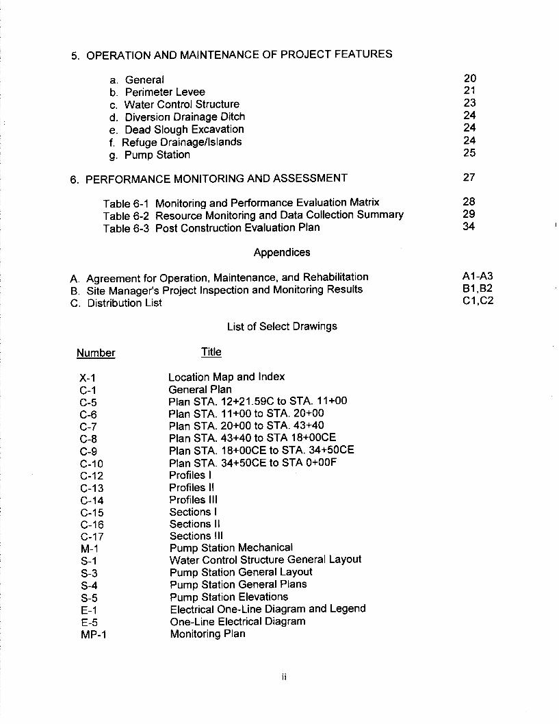
5. OPERATION AND MAINTENANCE OF PROJECT FEATURES
a. General b. Perimeter Levee c. Water Control Structure d. Diversion Drainage Ditch e. Dead Slough Excavation f. Refuge Drainage/Islands g. Pump Station
6. PERFORMANCE MONITORING AND ASSESSMENT 27
Table 6-l Monitoring and Performance Evaluation Matrix 28 Table 6-2 Resource Monitoring and Data Collection Summary 29 Table 6-3 Post Construction Evaluation Plan 34
Appendices
A. Agreement for Operation, Maintenance, and Rehabilitation Al -A3 B. Site Manager’s Project Inspection and Monitoring Results Bl ,B2 C. Distribution List Cl ,c2
X-l C-l C-5 C-6 c-7 C-8 c-9 C-IO c-12 C-l 3 c-14 C-l 5 C-16 c-17 M-l S-l s-3 s-4 s-5 E-l E-5 MP-1
List of Select Drawings
Location Map and Index General Plan Plan STA. 12+21.59C to STA. II+00 Plan STA. 1 I+00 to STA. 20+00 Plan STA. 20+00 to STA. 43+40 Plan STA. 43+40 to STA 18+00CE Plan STA. 18+00CE to STA. 34+50CE Plan STA. 34+50CE to STA O+OOF Profiles I Profiles II Profiles III Sections I Sections II Sections I I I Pump Station Mechanical Water Control Structure General Layout Pump Station General Layout Pump Station General Plans Pump Station Elevations Electrical One-Line Diagram and Legend One-Line Electrical Diagram Monitoring Plan
20 21 23 24 24 24 25

OPERATION AND MAINTENANCE MANUAL UPPER MISSISSIPPI RIVER SYSTEM
ENVIRONMENTAL MANAGEMENT PROGRAM
ANDALUSIA REFUGE REHABILITATION AND ENHANCEMENT
POOL 16, MISSISSIPPI RIVER MILES 462 THROUGH 463
1. INTRODUCTION.
a. Purpose and Scope.
(1) This manual will serve as a guide for the operation and maintenance of Andalusia Refuge Rehabilitation and Enhancement project. These instructions are consistent with the general procedures presented in the approved Definite Project Report. This manual has been written for project and management personnel familiar with the project and does not contain detailed information which is common to site personnel or which is presented in other existing manuals or regulations.
(2) The intent of the operating instructions is to provide information which allows orderly and efficient use of the constructed features to meet project goals and objectives. The intent of the maintenance instructions is to present preventative maintenance information consisting of systematic inspections and subsequent corrective actions which should ensure long-term utilization of equipment and features. A timely preventative maintenance program reduces and virtually eliminates breakdown of essential equipment and prevents major damage to constructed features by early corrective action.
(3) This manual provides the general standards of maintenance and establishes an initial frequency of maintenance inspections which should ensure satisfactory project performance.
b. Use of Manual.
(1) This manual is divided into the following sections: Section 1: Introduction; Section 2: Historical Summary; Section 3: Description of Project Features; Section 4: Inspections; Section 5: Operation and Maintenance of Project Features; and Section 6: Performance Monitoring and Assessment. Sections 2 and 3 present historical summaries and descriptions of actual features constructed for this project. Section 4 presents project inspection procedures and Section 5 presents operation and maintenance instructions for each project feature.

(2) Section 6 provides a summary of monitoring activities conducted through construction and provides an overview of continued monitoring actions. Performance monitoring is considered necessary to properly evaluate effects of the constructed project features.
(3) The attached as-built drawings provide general project plans and typical sections.
2. HISTORICAL SUMMARY.
a. Authorization and Location.
(1) The U.S. Army Corps of Engineers, Rock Island District, in cooperation with the U.S. Fish and Wildlife Service (USFWS) and the State of Illinois, Department of Conservation constructed and financed this project with authority granted in the 1985 Supplemental Appropriations Act (Public Law 99-88) and Section 1103 of the Water Resource Development Act of 1986, Public Law 99- 662.
(2) Andalusia Refuge is a backwater complex approximately 12 miles west of Rock Island, Illinois, on the Illinois side of the Upper Mississippi River and is located in pool 16. The project area is approximately at Upper Mississippi River mile 462.5 in Rock Island County, Illinois.
b. Planning and Construction Activities.
activities. (1) Table 2.1 provides a summary of planning and construction
2

-_ -
TABLE 2.1
Project Phase
SUMMARY OF PLANNING AND CONSTRUCTION ACTIVITIES Purpose Responsible Significant Events
Agency Item Date
Remarks
Pre-project identify and define problems and establish need of project.
USFWS Fact Sheet Submitted to Corps Approved by Corps
4187 6187
Design Quantify project objectives, perform preliminary design, satisfy NEPA and permit requirements, develop performance evaluation plan, obtain project approval for construction.
CORPS Definite Proiect Report Draft alaa Final 2189 Approved 6189
NEPA Compliance SHPO Concurrence 9l07iaa Public Review i2i23iaa FONSI for EA 2113ia9
Permits Section 401 1 ii 7189 Section 404 2113ia9

- -- -
TABLE 2.1 (CONTINUED)
SUMMARY OF PLANNING AND CONSTRUCTION ACTIVITIES
Project Phase
Construction
Purpose Responsible Significant Events Agency
Item Date Remarks
Finalize plans and CORPS Plans and specifications, obtain Specifications approval 5/30/89 operation and maintenance agreement, O&M Agreement 7/l 2189 See advertise and award Appendix A construction contract, Main Contract construct project Advertised 7124189
Awarded 8124189 Completed 918194
Post- Operate and maintain Construction project.
USFWS Reference Sections 4 and 5
Perform evaluation monitoring
CORPS Pet-form evaluation report
draft final supplements
Reference JUL 96 Section 6 OCT 96 annually
4

(2) Goals and objectives were formulated during the design phase. Table 2.2 provides a summary of project objectives.
TABLE 2.2
Project Goals and Obiectives
Goals
Enhance Migratory Waterfowl Habitat
Objective
Increase reliable food production area (moist soil species)
Unit of
Measure
Acres
Enhancement Potential
Existing Target
0 130
Increase reliable resting Acres 0 200 and feeding water area.
Enhance Restore deep (6 ft) Acre-Feet 0 40 Aquatic Habitat aquatic habitat
Restore lentic-lotic Square Feet 0 180 (minimum) habitat access cross- sectional area
Improve dissolved oxygen concentration during critical seasonal stress periods.
mg/l c4.0 mg/l >4.0 mg/l
Reduce Decrease adjacent Sedimentation tributary sediment in Refuge volume
Acre- FeeVYear
11 4.2

(3) The Rock island District, Corps of Engineers designed the project in cooperation with the USFWS and the Illinois DOC. Refer to the Definite Project Report for design considerations and investigations. The Corps of Engineers, Rock Island District administered and supervised the construction contract.
(4) Construction Problems:
Excavation in Dead Slough from approximately Station 20+00 to Station 36+00 was difficult due to high water content of the excavated material. The contractor’s use of drag lines contributed to the problem by not being able to maintain the in situ strength and water content of the excavated material.
Inflow to the pump station was interupted during the fall season when floating vegetation was abundant in the back waters. The river side trash rack plugged up with vegetation, primarily duckweed, not allowing sufficient water to feed the pump. To solve the problem 2 additional screens were added to filter the vegetation. A chain link fence screen was installed near the pump station and a fence screen with wider openings was installed approximately 140 ft from the pump station.
The Flood of 1993 caused minor erosion along the access road and silted in the ditches from Sta 12+00 to 16+00. The road and ditches were restored by contract modification. The river access channel into Dead Slough experienced greater than expected siltation rates. The access channel was excavated to a bottom elevation of 538.0
c. Actual Project Costs. The actual project costs are presented in Table 2.3.
TABLE 2.3
Actual Project Costs
Feature
0.6 FISH AND WILDLIFE FACILITIES.
ITEM DESCRIPTION QTY U/M ---_ _ U/P AMOUNT
0001 Clearing and Grubbing 1 LS $60,000.00 $60,000.00
0002 Settlement Drawings 2 EA 900.00 1,800.OO
0003A Excavation, River Access Channel
20,021 CY 6.25 125,131.25

ITEM
00038 Excavation, Access Road
0003c Excavation, Excess Embankment Between 24+17CE and 30+17CE
0003D Excavation, Refuge Islands/Drainage
0004A Embankment, Levee
0004B Embankment, Access Rd
0005A Stone Protection, Filter Fabric
0005B Stone Protection, Bedding
000X 1 Stone Protection Riprap Type A,
000X2 Stone Protection Riprap Type B,
0006 Overflow Cutoff Wall
0007 Pump Station
0008 Water Control Structure
0009 Culvert
DESCRIPTION ----- QTY U/M U/P AMOUNT
3,046
2,776.a
63,344.1
88,833
6,714
4,645
1,585.a
5,175.2
2,153.g
1
1
1
32
CY
CY
CY
CY
CY
SY
TN
TN
TN
LS
LS
LS
LF
4.50
4.50
3.50
3.65
4.50
5.00
13.00
23.50
23.50
25,ooo.oo
630,OOO.OO
70,600.OO
26.00
13,707.oo
12,495.60
221,704.35
324,240.45
30,213.OO
23,225.OO
20,615.40
121,617.20
50,616.65
25,OOO.OO
630,OOO.OO
70,600.OO
832.00

ITEM -.~ DESCRIPTION QTY U/M U/P AMOUNT
0010 Granular Surfacing/ Choke Stone
19425.5 TN 13.75 19,600.63
0011 Seeding 31 AC 1,650.OO 51,150.oo
0012 Vehicular Barrier Gates
3 EA 1,850.OO 5550.00
0013 Field Office 23 MO 725.00 16,675.OO
0014 24” CMP Culvert w/Flared End Sections
JB SUM 1,357.93
0015
0016
Water Deflection Drawing
Barricade Posts & Diversion Ditch
JB SUM 479.59
JB LS 6,533.89
0017 Pump Station Remedial Electrical & Mechanical Work
JB LS 6.804.80
0018 Silt Cleanup JB LS 2,101.21
0019 Revised Lightning Protection
LS __ 3,800.39
0020 (2) Staff Gages JB SUM 2,167.77
0021 Phase Converter/Electrical
JOB SUM 19.086.04
0022 Flood Repair JOB SUM 16,900.79
0023 Additional Pump Run
1
1
1
1
1
1
1
1
1
1 JOB SUM 402.98
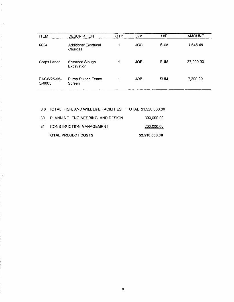
ITEM DESCRIPTION QTY U/M U/P AMOUNT
0024 Additional Electrical Charges
1 JOB SUM 1,648.46
Corps Labor Entrance Slough Excavation
1 JOB SUM 27,OOO.OO
DACW2595- Pump Station Fence 1 JOB SUM 7,200.OO Q-0005 Screen
0.6 TOTAL, FISH, AND WILDLIFE FACILITIES TOTAL $1,920,000.00
30. PLANNING, ENGINEERING, AND DESIGN 390,000.00
31. CONSTRUCTION MANAGEMENT 200,000.00
TOTAL PROJECT COSTS $2,510,000.00

d. Project References. Table 2.4 provides a summary of related project references.
Table 2.4
PROJECT REFERENCES
Title Date Purpose
Definite Project Report, Andalusia Refuge Rehabilitation and Enhancement With Environmental Assessment, U.S. Army Corps of Engineers, Rock Island District
Feb 89 Provided planning, engineering, and sufficient construction details of the selected plan for project approval purposes.
Construction As-builts Aug 95 Provides as-built construction drawings
Manufacturers’ Data (Shop Drawings)
Jul95 Provides detailed operation and maintenance instructions for specific pieces of equipment as recommended by the manufacturer.
IO

3. DESCRIPTION OF PROJECT
a. Project Data. Table 3.1
FEATURES.
presents a summary of project data.
Table 3.1
PROJECT DATA SUMMARY
tern
Perimeter Levee
Embankment Fill
_ength
Crown elevation
Quantity/Measurement Remarks
92,000 Cubic yards
8,600 Feet
552.8
552.8 to 551.8
Station 12+21 C to Station II+00
Varies from Station 1 1+00 to Station 24+17CE
550.8 From Station 25+17CE to Station 29+17CE
551.8 From Station 30+17CE to Station 34+50CE
Side Slopes 4:l Horizontal to vertical from Station 12+21 C to 8+00CE. Slopes
flattened for over flow and soft material placement purposes
4:l From Station 9+00CE to Station 34+50CE
Armored overflow levee section
_ength 600 Feet
3verftow elevation 550.8 MSL
II

Item
Riprap
Diversion Drainaqe Ditch
Approximate length
Average depth
Bottom slope
Watershed area
Capacity of channel
Dead Slouqh Channel Excavation
Adjacent to Levee
Approximate length
Width at bottom
Bottom elevation
Volume of excavation
River Access Excavation
Approximate length
Width at bottom
Bottom elevation
Quantity/Measurement
5,200 Tons
2 Feet
3 Feet
.0025 Foot per foot
1.152 Acres
340 CFS
4,500 Feet
60 Feet
36.0 MSL
87,000 CY
1,100 Feet
30 Feet
536 to 541 MSL
Remarks
(2-year precipitation event)

Volume of excavation
Refuge Drainaqehland Construction
Interior drainaqe with islands
Length
Width
Bottom Elevation
No. of islands
Area of an island above elevation 545.0
Interior drainaqe for adiacent levee borrow
Length
Width at bottom
Bottom elevation
Pump Station
Submersible pumps
Emptying pump
Filling pump
Quantity/Measurement
23,000 CY
8,600 Feet
40 Feet
542.02 MSL
27 Each
9.0 Acres
2,300 Feet
20 Feet
536.0 MSL
1 Each
1 Each
Remarks
6,775 gpm at 8.5 TDH rated
6,775 gpm at 8.5 TDH rated
I3

item Quantity/Measurement Remarks
Sluice gate 1 Each 3 feet x 3 feet
Operatinq elevations
Refuge max. elevation 550.8 MSL (overflow elevation)
Refuge min. elevation 542.0 MSL
Sump floor elevation 539.5 MSL
Equipment floor elevation 560.0 MSL (loo-year Mississippi River event)
Electric power source
Primary supply 7,620.O Volts 1 phase Secondary station supply
4801277 Volts 1 phase
Transformer size 37.5 WA 1 phase
Power converter 37.5 WA 3 phase
Trash racks
River and pond sides 2 Each
Fence screen river side 1 Each
Water Control Structure
Sluice gate 1 Each 3 feet x 3 feet
Invert 542.0 MSL

item Quantity/Measurement Remarks
Access Road
Approximate length 3,600 Feet
Width 12 Feet crushed stone surface
15

b. General Description.
The proposed project consists primarily of the construction of a 2-year event levee (elevation 550.8 MSL), pump station, and a water control structure. The levee is 8,600 feet long with a minimum top width of 12 feet. The levee system allows water level control on 130 acres of Refuge land. The pump station is capable of pumping 5,900 gallons per minute into or out of the Refuge. A General Plan View is shown on Drawing C-l. Fill material for the levee was excavated from Dead Slough, the Refuge, and from the diversion drainage ditch.
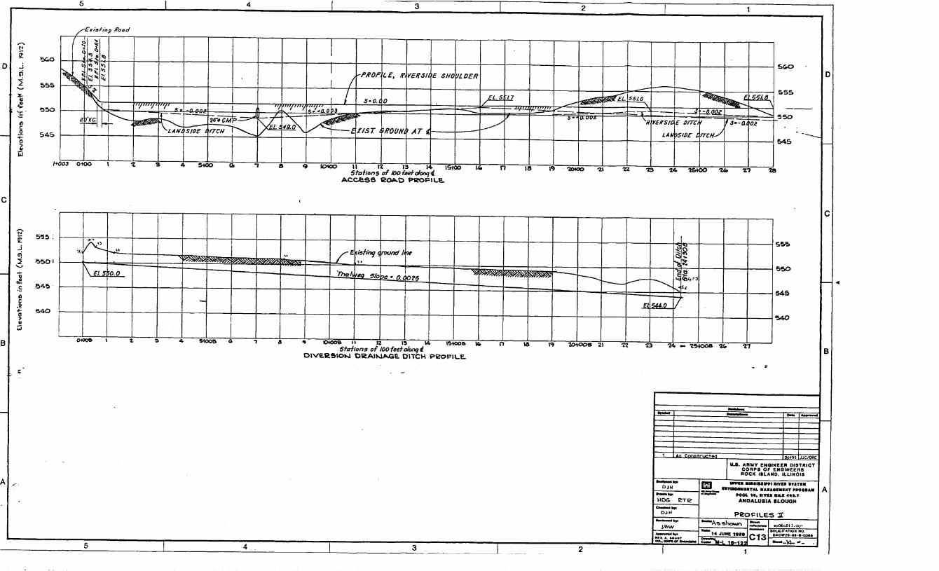
c. Perimeter Levee. The 2-year flood elevation for the project site is elevation 550.8 feet MSL, which represents the elevation of the overflow reach of the levee as shown on drawing C-9 from station 24+17CE to station 30+17CE (600 feet). From station 24+17CE to station 9+40 (see profile on drawing C-12), the profile of the levee is approximately five times steeper than the natural flood profiles of the Mississippi River. A detailed description of the operational features of the levee system is presented in Section 5.
(1) Station 12+21 C to Station 11 +OO. This reach of levee, as shown on drawing C-5, consists of a 12-foot-wide crown with an approximate height of 4 feet. Typical section is shown on drawing C-15. Borrow for this approximately 1,300 feet of levee was excavated from the nearby diversion drainage ditch and from Dead Slough excavation.
(2) Station 1 I+00 to Station 8+00CE. This reach of levee of about 4,100 feet consists of an approximate 60-foot-wide levee crown with 4: 1 (Horizontal:Vertical) side slopes, as shown in plan on drawings C-6, C-7, and C-8 and with typical section on drawing C-15. It is located adjacent to Dead Slough such that approximately 40 feet of the levee section lies on existing ground above flat pool (elevation 545.0) with the remainder of the levee section lying within Dead Slough on land below flat pool (average elevation 544.0). This reach of the levee system has a substantially thicker section due to the placement requirement of adjacent Dead Slough excavation. The average height of this levee is 6 feet.
The overbuilt section on the slough side will require minimal maintenance. The other half of this levee section is the integral core of the levee and will require annual inspection and maintenance.
(3) Station 9+00CE to Station 24+17CE. This reach of the levee consists of approximately 1,600 lineal feet and has an average height of about 6 feet with 4:l side slopes. This reach was constructed using adjacent borrow sources, as shown on drawings C-8 and C-9, with typical section on drawing C-15. The width of the levee crown on this reach is 12 feet.
16

(4) Station 24+17CE to Station 30+17CE. This reach of the levee consists of approximately 600 feet crossing the most downstream area of the MSMU. Average height of this levee is about 7 feet, with a 12-foot clay core and a 2-foot bedding and riprap blanket on the exterior for overflow and wave protection. This reach is shown on drawing C-9, with typical section on drawing C-15.
Borrow for this section of levee was obtained from adjacent in-water excavation. Typical side slopes are 4:l.
(5) Station 30+17CE to Station 34+50CE. This 433-foot reach of the levee is shown on drawing C-8 and C-9, with typical section on drawing C-16. This section of levee ties into high ground and is connected to the access road. Average height in this reach will be approximately 2 feet. Borrow was obtained from areas adjacent to the access road.
d. Diversion Drainage Ditch. The plan view of the diversion ditch is shown on drawing C-5, with section shown on drawing C-15. The bottom width of the excavated ditch is approximately 30 feet, with average depth of excavation of 3 feet. The drainage ditch was sized to pass a 2-year precipitation event within bank.
The outlet of the diversion drainage ditch was placed near flat pool in Scisco Chute which closely approximates the existing outlet and should minimize outlet area maintenance.
The entire drainage diversion ditch is located on existing Government lands; no additional easements/fee taking is required. As shown on the typical section, an additional 1 O-foot-wide unsurfaced maintenance access service road is available for site access. The contractor did not use this access during construction. The access is currently over-grown with vegetation. It does not require maintenance unless its use is desired.
e. Dead Slough Excavation. As shown on drawings C-6, C-7, and C-8, with typical sections on drawing C-l 5, the contractor excavated approximately 85,000 cubic yards for Dead Slough aquatic improvement. The average bottom width of this excavation is about 60 feet. The slough was excavated to elevation 536 MSL adjacent to the levee. The average cut for this excavation was approximately 7 feet. The excavated material was placed in the levee section adjacent to Dead Slough, as described in the above perimeter levee, from station 1 l+OO to station 8+00CE.
A river access channel was constructed from Scisco Chute to the Dead Slough area. The approximately 1,100 feet of excavation will consist of a 30-foot-wide cut with a depth that varies from elevation 536 to 541 MSL, with excavated material placed on adjacent land between stations 8E to 13E, as shown in section on drawing C-16. This depth will be maintained with an effort described in the Definite Project Report. Additional excavation may be required but will only be accomplished when funding is available.
17
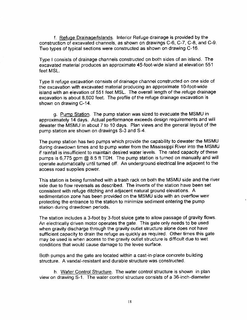
f. Refuge Drainaqe/lslands. Interior Refuge drainage is provided by the construction of excavated channels, as shown on drawings C-6, C-7, C-8, and C-9. Two types of typical sections were constructed as shown on drawing C-16.
Type I consists of drainage channels constructed on both sides of an island. The excavated material produces an approximate 45foot-wide island at elevation 551 feet MSL.
Type II refuge excavation consists of drainage channel constructed on one side of the excavation with excavated material producing an approximate 1 O-foot-wide island with an elevation of 551 feet MSL. The overall length of the refuge drainage excavation is about 8,600 feet. The profile of the refuge drainage excavation is shown on drawing C-14.
g. Pump Station. The pump station was sized to evacuate the MSMU in approximately 14 days. Actual performance exceeds design requirements and will dewater the MSMU in about 7 to IO days. Plan views and the general layout of the pump station are shown on drawings S-3 and S-4.
The pump station has two pumps which provide the capability to dewater the MSMU during drawdown times and to pump water from the Mississippi River into the MSMU if rainfall is insufficient to maintain desired water levels. The rated capacity of these pumps is 6,775 gpm @ 8.5 ft TDH. The pump station is turned on manually and will operate automatically until turned off. An underground electrical line adjacent to the access road supplies power.
This station is being furnished with a trash rack on both the MSMU side and the river side due to flow reversals as described. The inverts of the station have been set consistent with refuge ditching and adjacent natural ground elevations. A sedimentation zone has been provided on the MSMU side with an overflow weir protecting the entrance to the station to minimize sediment entering the pump station during drawdown periods.
The station includes a 3-foot by 3-foot sluice gate to allow passage of gravity flows. An electrically driven motor operates the gate. This gate only needs to be used when gravity discharge through the gravity outlet structure alone does not have sufficient capacity to drain the refuge as quickly as required. Other times this gate may be used is when access to the gravity outlet structure is difficult due to wet conditions that would cause damage to the levee surface.
Both pumps and the gate are located within a cast-in-place concrete building structure. A vandal-resistant and durable structure was constructed.
h. Water Control Structure. The water control structure is shown in plan view on drawing S-l. The water control structure consists of a 36-inch-diameter
18

concrete conduit located within the levee section. The invert of the conduit is at elevation 542.0 feet MSL. A 3-foot by 3-foot sluice gate controls water flow. The gate may be operated manually or with a portable power source. The hydraulic power operator should not be run to the extreme ends of the gate operating limits to avoid damage to the gate and stem.
i. Access Road. The access road consists of the construction of approximately 3,600 lineal feet of a 12-foot-wide service road, with typical sections on drawing 19. IDOC personnel will control egress to the access road to prevent and minimize public access to the refuge area and consequent disturbance.
4. INSPECTIONS.
a. General.
(1) An active maintenance program is based on inspections and subsequent servicing, adjustment, or repair. There are 2 main objectives of inspections: (1) to insure project serviceability by timely and thorough inspections thereby avoiding or reducing maintenance costs, and (2) to document the condition of the project as a baseline for consideration of rehabilitation for project damage resulting from a major storm or flood event.
(2) There are 2 types of inspections for the project: (1) Project Inspection by the Site Manager and (2) Joint Inspection by the Site Manager and personnel from the Corps of Engineers, Rock Island District.
b. Project Inspection bv Site Manager.
(1) The Project Inspection should be performed by the Site Manager or appropriate representative for the purpose of noting routine deficiencies and initiating corrective actions. This inspection will be performed at periods not exceeding 12 months and will follow inspection guidance presented in subsequent sections of this manual. It is suggested that the inspection be conducted every May, which is representative of after spring flood conditions. Other Project Inspections should occur as necessary after high water events or as scheduled by the Site Manager.
(2) A Project Inspection checklist has been developed as presented in Appendix B. It is suggested that a copy of the completed checklist be furnished to the Corps of Engineers, Rock island District, ATTN: CENCR-OD-S, P.O. Box 2004, Rock Island, Illinois, 61204-2004, immediately following each Project Inspection by the Site Manager.
c. Joint Inspection by Site Manager and Corps of Engineers.
19

(1) Routine. A Joint inspection by the Site Manager and the Corps of Engineers will be scheduled by the Corps in accordance with ER 1130-2-339. The purpose of this inspection is to assure that adequate maintenance is being performed as presented in the DPR and this manual. The District Engineer or Authorized Representatives should have access to all portions of the constructed project upon coordination with the Site Manager for this purpose. Copies of this inspection will be furnished to the Site Manager stating project maintenance conditions. Corrective actions from these inspections should be accomplished by the Site Manager as provided by USFWS, Operation, Maintenance, and Rehabilitation Agreement, reference appendix A.
(2) Catastrophic. A Joint Inspection by the Site Manager and the Corps of Engineers should be formally requested by the Site Manager immediately following a specific storm or flood event which causes damage exceeding the annual operation and maintenance as specified in this manual and the Definite Project Report. The Project Inspections by the Site Manager and Joint Inspection results will be the basis for determining maintenance responsibility and potential rehabilitation by the Corps of Engineers.
5. OPERATION AND MAINTENANCE OF PROJECT FEATURES.
a. General.
(1) This section presents operation and maintenance instructions for the major project features which were designed and constructed to minimize operation and maintenance requirements.
(2) Steps will be taken by the Site Manager to correct conditions disclosed by Project Inspections or Joint Inspections. Regular maintenance repair measures will be accomplished during the appropriate season as scheduled by the Site Manager to insure serviceability.
(3) Project features should be continuously maintained and operated to obtain maximum benefits. No encroachment or trespass which will adversely affect the efficient operation or maintenance of the project should be permitted upon the constructed features. No improvement should be passed over, under, or through the constructed features, nor should any excavation or construction be permitted within these features without prior approval by the Corps of Engineers, Rock Island District. Such improvements or alterations which are desirable and permissible should be constructed in accordance with standard engineering practice. Advice regarding the effect of proposed improvements or alterations on the functioning of the project and information concerning methods of construction acceptable under standard engineering practice should be obtained from the District Engineer or if otherwise obtained, should be submitted for approval. Drawings or prints showing improvements or alterations as finally constructed should be furnished to the District Engineer after completion of such work.
20

b. Perimeter Levee.
(1) Operation.
(a) During flood periods, the levee should be inspected to locate possible sand boils or unusual wetness of the landward slope and to be certain that:
(i) There are no indications of slides or sloughs developing;
(ii)
(iii) which may be overtopped;
structure. (iv)
Wave wash or scouring action is not occurring;
No low reaches of levee below design grade exist
No other conditions exist which might endanger the
(b) Appropriate advance measures should be taken to insure the availability of adequate labor and materials to meet contingencies. Steps should be taken to control any condition which endangers the levee and to repair the damaged section. If additional riprap is needed to protect eroding banks, the material presented in Table 4-1, or equivalent material should be used.
Table 5-1
ANDALUSIA REFUGE RIPRAP SIZE*
Stone Weight Pounds Minimum Percent Larger Than
250
90
5
* Iowa Class “D” riprap may be used.
(2) Maintenance.
0
50
90
(a) The Site Manager should provide at all times such maintenance as may be required to insure serviceability of the levee in time of flood.
21

Measures should be taken to promote the growth of sod and control burrowing animals. This includes routine mowing or burning (a minimum of twice per year) on the levees extending 5 feet horizontally from the toe of the levee, removal of wild growth and drift deposits, and repair of damage caused by erosion or other forces.
(b) Project inspections should be made by the Site Manager to insure that the above maintenance measures are being effectively carried out and to be certain that:
(i) no unusual settlement, sloughing, or material loss of grade or levee cross-section has taken place;
(ii) no caving has occurred on either the landside or the riverside of the levee which might affect the stability of the levee section;
occurring; (iii) no seepage, saturated areas, or sand boils are
(iv) no revetment work or riprap has been displaced, washed-out, or removed;
(v) no action is being taken, such as burning grass and weeds during inappropriate seasons, which will retard or destroy the growth of sods;
(vi) the crown of the levee is shaped to drain readily;
on the levee; (vii) there is no unauthorized grazing or vehicular traffic
(viii) encroachments are not being made on the levee which might endanger the structure or hinder its proper and efficient functioning during times of flood.
(c) Such inspections should be made prior to the beginning of the flood season, immediately following major high-water periods, and otherwise at intervals necessary to insure the best care of the levee or 1 time per year as stated in section 4b. Steps should be taken to correct conditions disclosed by such inspections. Regular maintenance repair measures should be accomplished during the appropriate season as scheduled by the Site Manager.
22

c. Water Control Structure.
(1) Operation.
(a) When the MSMU is in use, or water levels of the Mississippi River rise with heavy sediment loads, the gatewell structure should be closed to prevent sediment from entering upper Andalusia Refuge Lake. The gates should remained closed until:
(i) heavy sed’ rment flood waters recede; and/or
(ii) low diss I d o ve oxygen conditions exist in Andalusia Refuge Lakes;
(iii) the MSMU is not in use;
(iv) the river reaches elevation 550 MSL (which is 15 feet on the Fairport gage) with predicted stage to increase. Both the outlet structure gate and the pump station gate should be opened to minimize overtopping erosion.
(b) This structure was provided with a portable power source and adapter to power lift the gate. The operating stand, electric generator, and drill adapter should be stored off-site to allow ready use when needed.
(2) Maintenance.
(a) The drainage structure should be inspected during floods to determine whether seepage is taking place along the lines of its contact with the embankment. Steps should be taken to correct any adverse condition.
(b) The gate of the structure should be examined, lubricated, and trial-operated at least once a year. Follow the manufacturer’s instructions for lubrication.
(c) Project inspections of the control structure should be made by the Site Manager to be certain that:
(i) Pipes, gates, operating mechanism, riprap, and headwalls are in good condition;
(ii) Inlet and outlet channels are open;
(iii) Care is being exercised to prevent the accumulation of trash and debris near the structures;
23

(iv) Erosion is not occurring adjacent to the structure which might endanger its function.
(d) Steps should be taken to repair damage, replace missing or broken parts, or remedy adverse conditions disclosed by such inspections.
d. Diversion Drainage Ditch.
(1) Operation. The improved channel should be inspected immediately following major high water periods. As soon as practicable after high water events, all snags and other debris should be removed from the channel.
(2) Maintenance.
(a) Project inspections of the improved channel should be made by the Site Manager to be certain that:
growth; (i) The channel is cleared of debris, weeds, and wild
(ii) The channel is not being restricted by the depositing of waste materials, building of unauthorized structures, or other encroachments;
(iii) Banks are not being damaged by rain or wave wash and that no sloughing of banks has occurred;
(b) Steps should be taken to correct conditions disclosed by such inspections.
e. Dead Slough Excavation.
Section 5d should be followed for operation and maintenance of this feature.
f. Refuge Drainage/Islands.
(1) Operation. Specific operational requirements should be performed as determined by the Site Manager.
(2) Maintenance. Project Inspections of the dredged lake channels should be made by the Site Manager to record the presence of debris, waste materials, unauthorized structures, and sedimentation deposits, Such inspections may use visual observation and sufficient pole soundings.
24

g. Pump Station.
(1) Operation. The gate of the pump station should normally be closed. If its use is required as stated in paragraph 39, or if overtopping is expected, the gate should be opened. During desired drawdown periods, the gate of the water control structure and the pump station should be closed and the pump station activated for drawdown purposes. The pump station must be manually activated but will automatically turn off at a low water level of 542.0 MSL. During drawdown periods, the pump station will automatically turn on at elevation 542.5 MSL to maintain the 542.0 drawdown elevation. The IDOC may make minor adjustments to these levels to suit refuge management purposes.
After drawdown has occurred and once vegetation has been established in the MSMU, either adjacent tributary inflow, seepage, or opening of the water control structure gate or the pump station gate will allow water into the MSMU area. Use of gates and pumps should be controlled to achieve desired water levels consistent with vegetative growth.
When it is desired to pump from the river into the MSMU, the station must be manually activated and will continue pumping automatically. The pump will automatically shut off at elevation 547.0 MSL (which can be adjusted to elevation 550.8, the elevation of the levee overflow). It is anticipated that ponding levels higher than elevation 547.0 will cause damage to adjacent agricultural fields during crop growing seasons. The IDOC must coordinate with adjacent property owners during the non-crop season prior to raising MSMU water elevations above 547.0. IDOC must determine the trade-off of operating higher than 547.0 for additional MSMU acres versus potential negative impacts and associated coordination. The highest MSMU elevation 550.8 MSL will occur when water reaches the elevation of the overflow weir.
I During periods of drawdown and when river events reach elevation 550.0 MSL (which is 15 feet on the Fairport gage at river mile 462.7) with predicted stage to increase, the gates of the water control structure and the station should be opened in efforts to fill the interior of the levee without overtopping. Should the river stage exceed 550.8 MSL prior to filling using the existing water control structure and pump station conduits, the remainder of overflow will occur by means of a riprapped overflow weir station.
(2) Maintenance. Pump station inspections will be performed by the site manager. Steps should be taken to correct conditions disclosed by such inspections. The pump station inspection should include the following:
(a) Building. Visually inspect all surfaces to discover cracks, spalling of concrete, broken blocks or bricks, faulty joints, check around all opening for cracks and leaks.
25

(b) Gates. When operating conditions will permit, operate through a portion of their travel to determine that gates are in satisfactory condition. Examine exposed parts of gates for corrosion, cracking, deterioration of coating and other damage. Check rivets, bolts and welds. Repair when conditions will economically justify the work.
(c) Pumps.
(i) Pump should be observed for indications of improper operation or damage. Avoid operation of pump during sump cavitation or ice conditions. The pump will automatically shut down through the pump control unit located in the electrical panel on high stator winding temperature, stator casing leakage, or high bearing temperature. Test lights for these shutdown alarms should be checked before starting the respective pump. The pump station sluice gate must be fully closed to start either pump. This is due to an electrical interlock that de- energizes the pump control circuitry if the gate is not fully closed. Periodically check the sump for proper water depth, especially prior to extended operation. Mud in the sump may be a cause for cavitation during operation.
(ii) The Site Manager should have an authorized representative conduct pump inspections and maintenance and repair work in accordance with, “KSB PNT Submersible Motor-Propeller Pumps.” Ancillary equipment such as cables, level sensors, starter and monitoring equipment should also be periodically inspected. Damaged components should be repaired or replaced by a qualified mechanic or electrician.
(d) Control Panel - Examine closely for over all condition. Tighten, repair, and clean as needed.
(e) Trash Racks - Check for trash accumulation at racks and remove as necessary. Should operating conditions or observations indicate trouble is developing and operating conditions will permit, inspect sufficient racks to indicate general condition. Repair as necessary to maintain a satisfactory condition. Underwater inspection of racks may be more practical than removal of racks.
h. Access Road.
The access road will require periodic maintenance to clear culverts and drainage ditches, add additional surface stone, and replenish embankment rip rap. The surface stone is Illinois DOT gradation CA 6. The rip rap size is shown in table 5-1.
26

6. PERFORMANCE MONITORING AND ASSESSMENT
a. The purpose of this section is to summarize monitoring and data collection aspects of the project. Table 6-l presents the principal types, purposes, and responsibility of monitoring and data collection. Table 6-2 provides a summary of actual monitoring and data parameters grouped by project phase, responsible agency, and data collection intervals. Changes to the monitoring plan should be coordinated with the USFWS, IDOC, and COE.
b. Table 6-3 presents the post-construction evaluation plan. The monitoring parameters were developed to measure the effectiveness of the stated goals. The Site Manager should follow Table 6-3, as shown, to make annual field observations. The annual field observations and the quantitative monitoring parameters will form the basis of project evaluation.
,
27

TABLE 6-l
MONITORING AND PERFORMANCE EVALUATION MATRIX
Project Phase
Pre - Project
Type of Activity
Sedimentation Problem Analysis
Pre-project Monitoring
Purpose Responsible Implementing Funding Implementation Agency Agency Source Instructions
System-wide problem definition. Evaluate USFWS USFWS (EMTC) LTRM I/ -- planning assumptions
Identifies and defines problems at HREP USFWS USFWS USFWS -- site. Establish need of proposed project features.
Baseline Monitoring Establishes baselines for performance evaluation
Corps Corps LTRM See Table 6-2
Design Data Collection for Design
Includes quantification of project objectives, design of project, and development of performance evaluation plan.
Corps Corps HREP 2/ See Table 6-2
Construction Construction Monitoring
Post Performance Evaluation Construction Monitoring
Assess construction impacts; assures Corps Corps HREP See State Section permit conditions are met 401 Stipulations
Determine success of project as related to Corps Corps USFWS LTRM See table 6-3 objectives (quantitative)
sponsor (Field Observation)
Analysis of Biological Responses to Projects
Evaluate predictions and assumptions of habitat unit analysis. Studies beyond scope of performance evaluation, or if projects do not have desired biological results.
Corps Corps LTRM --
11 Long Term Resource Monitoring of the Environmental Management Program (P.L. 99-662) 21 Habitat Rehabilitation and Enhancement Project of the Environmental Management Program (P.L. 99-662)
28
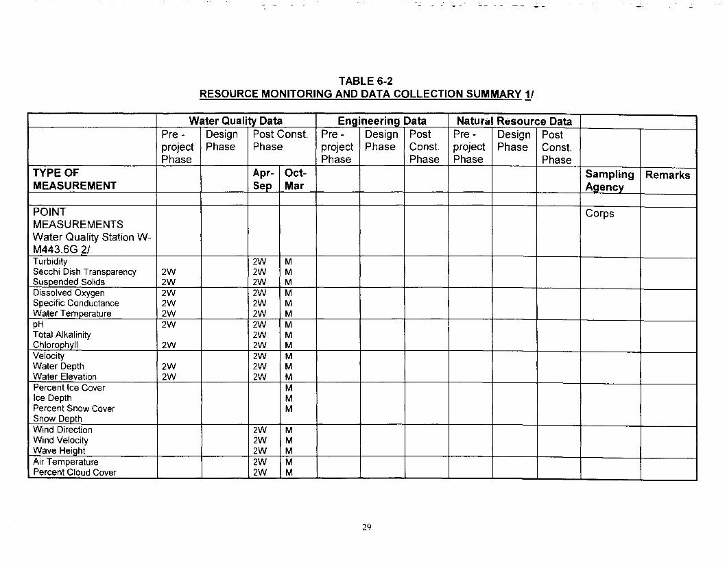
TABLE 6-2 RESOURCE MONITORING AND DATA COLLECTION SUMMARY I/
TYPE OF MEASUREMENT
Water Quality Data Engineering Data Natural Resource Data Pre - Design Post Const. Pre - Design Post Pre - Design Post project Phase Phase project Phase Const. project Phase Const. Phase Phase Phase Phase Phase
Apr- Oct- Sampling Remarks Sep Mar Agency
POINT Corps MEASUREMENTS Water Quality Station W- M443.6G 21 Turbidity 2W M Secchi Dish Transparency 2W 2W M Suspended Solids 2w 2W M Dissolved Oxygen 2w 2W M Specific Conductance 2w 2W M Water Temperature 2w 2W M PH 2w 2W M Total Alkalinity 2W M Chlorophyll 2w 2W M Velocity 2W M Water Depth 2w 2W M Water Elevation 2w 2W M Percent Ice Cover M Ice Depth M Percent Snow Cover M Snow Depth Wind Direction 2W M Wind Velocity 2W M Wave Height 2W M Air Temperature 2W M Percent Cloud Cover 2W M
29

-
TABLE 6-2 RESOURCE MONITORING AND DATA COLLECTION SUMMARY I/
Water Quality Data Engineering Data Natural Resource Data Pre - Design Post Const. Pre - Design Post Pre - Design Post project Phase Phase project Phase Const. project Phase Const. Phase Phase Phase Phase Phase
TYPE OF Apr- Oct- Sampling Remarks MEASUREMENT Sep Mar Agency
POINT MEASUREMENTS Sediment Test Station 31 Corps Elutriate 1 Bulk Sediment 1
Column Settling Stations Corps 41 Column Settling Analysis 1
Boring Stations 5/ Corps Geotechnical Borings 1
TRANSECT MEASUREMENTS Sedimentation Transects 61 Hydrographic Soundings
Sedimentation Transects 71 Hydrographic Soundings Veaetation Transects 8/
Corps
Corps
Cortx
30

-- -- _ __ __ ---- -- __ &- _
TYPE OF MEASUREMENT
AREA MEASUREMENTS Mapping 91 Aerial Photography
TABLE 6-2 RESOURCE MONITORING AND DATA COLLECTION SUMMARY 11
Water Quality Data Pre - Design Post Con&. project Phase Phase Phase
Apr- Oct- Sep Mar
LEGEND FOR TABLE 6-2
W = Weekly M = Monthly Y = Yearly nW = n-Week Interval nY = n-Year Interval 1,2,3,... = number of times data is
collected within designated project phase
Engineering Data Natural Resource Data 1
Pre - Design Post Pre - Design Post project Phase Const. project Phase Const. Phase Phase Phase Phase
Sampling Remarks Agency
I I I I
1 1 Corps I
5Y I
31
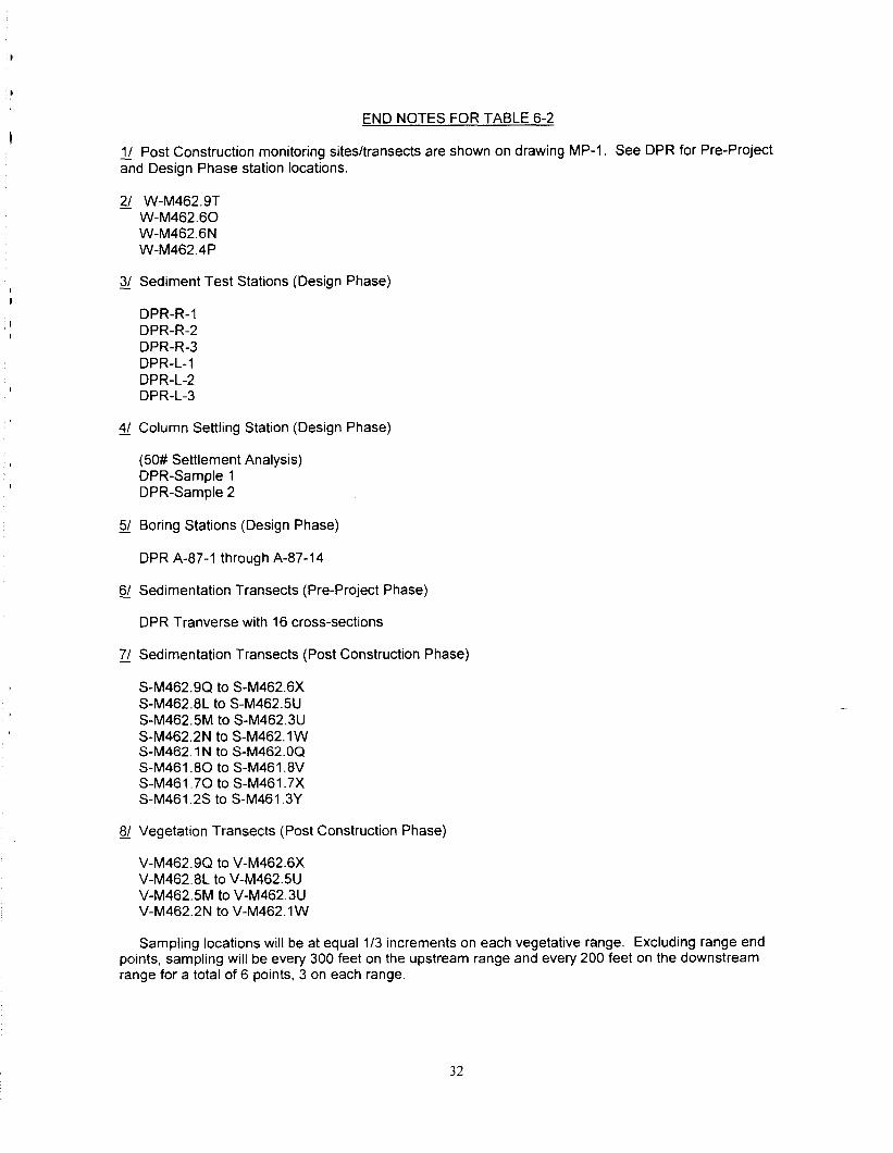
END NOTES FOR TABLE 6-2
1/ Post Construction monitoring sites/transects are shown on drawing MP-1. See DPR for Pre-Project and Design Phase station locations.
21 W-M462.9T W-M462.60 W-M462.6N W-M462.4P
3/ Sediment Test Stations (Design Phase)
DPR-R-1 DPR-R-2 DPR-R-3 DPR-L-1 DPR-L-2 DPR-L-3
41 Column Settling Station (Design Phase)
(50# Settlement Analysis) DPR-Sample 1 DPR-Sample 2
51 Boring Stations (Design Phase)
DPR A-87-l through A-87-14
s/ Sedimentation Transects (Pre-Project Phase)
DPR Tranverse with 16 cross-sections
71 Sedimentation Transects (Post Construction Phase)
S-M462.9Q to S-M462.6X S-M462.8L to S-M4625U S-M462.5M to S-M462.3U S-M462.2N to S-M462.1 W SM462.1 N to S-M462.OQ S-M461.80 to S-M461.8V S-M461.70 to S-M461.7X S-M461.2S to S-M461.3Y
8/ Vegetation Transects (Post Construction Phase)
V-M462.9Q to V-M462.6X V-M462.8L to V-M4625U V-M462.5M to V-M462.3U V-M462.2N to V-M462.1 W
Sampling locations will be at equal l/3 increments on each vegetative range. Excluding range end points, sampling will be every 300 feet on the upstream range and every 200 feet on the downstream range for a total of 6 points, 3 on each range.
32

91 Mapping (Post Construction Phase)
Aerial survey will be performed of the project area to determine the amount of waterfowl resting and feeding water areas and to inventory potholes.
33

Table 6-3
Post Construction Evaluation Plan
; SoaVObjective
1
-i
Enhancement Unit Year 0 Year X Year 50 Feature Annual Field Feature without with Target Measurement Observation by
Alternative Alternative with Reference Table 6-2 Site Manager Alternative
Enhance Migratory Waterfowl Habitat Increase reliable food production Provide water Acres 0 __ 130 Perform Vegetation Development of area (Moist soil species) control Transects 81 Emergent Vegetation Increase reliable resting and Mechanical Acres 0 __ 200 Perform hydrographic Waterfowl presence or feeding water area Dredging soundings of transects absence
71
Enhance Aquatic Habitat Restore deep (6 ft) aquatic habitat Mechanical Acre- 0 __ 40 Perform hydrographic Development of
Dredging feet soundings of transects emergent vegetation z! within deep dredged
areas Restore Lentic-Lotic habitat access Mechanical Sq. 0 __ 180 Perform hydrographic Development of cross-sectional area Dredging feet soundings of transects emergent vegetation
Excavation 71 within access area Improve dissolved oxygen Mechanical Mgll c 4.0 __ > 4.0 Perform water quality Fish stress or fish kills concentration during critical stress Dredging and testing at stations j_/ periods Gated Inlet
Structure Reduce sedimentation in refuge Construct Levee Acre- 11 __ 4.2 Perform hydrographic Shoaling in shallow
and divert feet I soundings of transects areas tributary year 71
I I I I I I I
34

APPENDIX A
Agreement for Operation, Maintenance and Rehabilitation

12 July 1989
MEMORANDUM OF AGREEMENT BETWEEN
THE UNITED STATES FISH AND WILDLIFE SERVICE AND
THE DEPARTMENT OF THE ARMY FOR
ENHANCING FISH AND WILDLIFE RESOURCES OF THE
UPPER MISSISSIPPI RIVER SYSTEM AT
ANDALUSIA REFUGE, ILLINOIS
I. PURPOSE
The purpose of this Memorandum of Agreement (MOA) is to establish the relationships, arrangements, and general procedures under which the U.S. Fish and Wildlife Service (FWS) and the Department of the Army (DOA) will operate in constructing, operating, maintaining, repairing, and rehabilitatinq the Andalusia Refuge, IL, separable element of the Upper Mississippi River System -- _ Environmental Management Program (UMRS-EMP).
II. BACKGROUND
Section 1103 of the Water Resources Development Act of 1986, Public Law 99-662, authorizes construction of measures for the purpose of enhancing fish and wildlife resources in the Upper Mississippi River System. Under conditions of Section 906(e) of the Water Resources Development Act of 1986, Public Law 99-662, all construction costs of those fish and wildlife features on the Andalusia Refuge are 100% Federal, and all operation, main- tenance, repair, and rehabilitation costs are to be cost shared, 75% Federal and 25% non-Federal.
III. GENERAL SCOPE
The project to be accomplished pursuant to this MOA shall consist of creating a reliable food supply for migratory water- fowl, providing water level control on 130 acres of wetland, the creation of 9 acres of island habitat for the nesting of Canada geese, and the construction of deeper channels in the backwater area of Andalusia Refuge.
IV. RESPONSIBILITIES
A. DOA is responsible for:
1. Construction: Construction of the project which consists of creating a reliable food supply for migratory water- fowl, providing water level control on 130 acres of wetland, the

creation of 9 acres of island habitat for the nesting of Canada geese, and the construction of deeper channels in the backwater area of Andalusia Refuge.
2. Major Rehabilitation: Any mutually agreed upon rehabilitation of the project that exceeds the annual operation and maintenance requirements identified in the Definite Project Report and that is needed as a result of specific storm or flood events.
3. Construction Management: Subject to and using funds appropriated by the Congress of the United States, DOA will construct the Andalusia Refuge Fish and Wildlife Enhancement Project as described in the Definite Project Report, "Andalusia Refuge Rehabilitation and Enhancement," dated January 1989, applying those procedures usually followed or applied in Federal projects, pursuant to Federal laws, regulations, and policies. The FWS will be afforded the opportunity to review and comment on all modifications and change orders prior to the issuance to the contractor of a Notice to Proceed. If DOA encounters potential delays related to construction of the project, DOA will promptly notify FWS of such delays.
4. Maintenance of Records: DOA will keep books, records, documents, and other evidence pertaining to costs and expenses incurred in connection with construction of the project to the extent and in such detail as will properly reflect total costs. DOA shall maintain such books, records, documents, and other evidence for a minimum of three years after completion of construction of the project and resolution of all relevant claims arising therefrom, and shall make available at its offices at reasonable times, such books, records, documents, and other evidence for inspection and audit by authorized representatives of the FWS.
B. FWS is responsible for:
1. Operation, Maintenance, tion of construction as determined by Rock Island, the FWS shall accept the
and Repair: Upon comple- the District Engineer, project and shall operate, -.
maintain, and repair the project as defined in the Definite Project Report entitled "Andalusia Refuge Rehabilitation and Enhancement," dated January 1989, in accordance with Section 906(e) of the Water Resources Development Act, Public Law 99-662.
2. Non-Federal Responsibilities: In accordance with Section 906(e) of the Water Resources Development Act, Public Law 99-662, the FWS shall obtain 25% of all costs associated with the operation, maintenance, and repair of the project from the Illinois Department of Conservation.

V. MODIFICATION AND TERMINATION
This MOA may be modified or terminated at any time by mutual agreement of the parties. Any such modification or termination must be in writing. Unless otherwise modified or terminated, this MOA shall remain in effect for a period of no more than 50 years after initiation of construction of the project.
VI. REPRESENTATIVES
The following individuals or their designated representatives shall have authority to act under this MOA for their respective parties:
FWS: Regional Director U.S. Fish and Wildlife Serevice Federal Building, Fort Snelling Twin Cities, Minnesota 55111
DOA: District Engineer U.S. Army Engineer District, Rock Island Clock Tower Building - P.O. Box 2004 Rock Island, Illinois 61204-2004
VII. EFFECTIVE DATE OF MOA
This MOA shall become effective when signed by the appropriate representatives of both parties.
THE U.S. FISH AND WILDLIFE SERVICE _
BY: w C. GRITMANY _
Colonel U.S. Army Engineer District, b Rock Island Corps of Engineers
Regional Director U.S. Fish and Wildife
Service
APPENDIX B
Site Manager’s
Project Inspections And Monitoring Results

ANDALUSIA REFUGE REHABILITATION AND ENHANCEMENT OPERATION AND MAINTENANCE MANUAL
UPPER MISSISSIPPI RIVER ENVIRONMENTAL MANAGEMENT PROGRAM POOL 16, RIVER MILES 462 THROUGH 463
ROCK ISLAND, ILLINOIS
SITE MANAGER’S PROJECT INSPECTION AND MONITORING RESULTS
Inspected by Date Type of Inspection (annual) (emergency-disaster) (other)
1. PROJECT INSPECTION.
!&l Comment/Condition
a. Perimeter Levee.
( ) Settlement, sloughs, or loss of section. ( ) Seepage, saturated areas, sand boils. ( ) Wave-wash, scouring. ( ) Overtopping erosion. ( ) Vegetative cover (mowing). ( ) Displaced/missing riprap. ( ) Burrowing animals. ( ) Unauthorized grazing or traffic. ( ) Encroachments.
b. Water Control Structure.
( ) Pipes, gates, and operating mechanisms. ( ) Concrete. ( ) Displaced/missing riprap. ( ) Blockage of inlet and outlet channels. ( ) Erosion adjacent to structure.
c. Diversion Drainage Ditch.
( ) Debris. ( ) Waste materials/unauthorized structures. ( ) Bank Erosion.
B-l
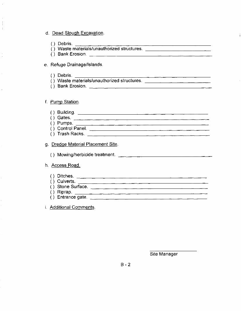
d. Dead Slouqh Excavation.
( ) Debris. ( ) Waste materials/unauthorized structures. ( ) Bank Erosion.
e. Refuge Drainage/Islands.
( ) Debris. ( ) Waste materials/unauthorized structures. ( ) Bank Erosion.
f. Pump Station.
( ) Building. ( ) Gates. ( ) Pumps. ( ) Control Panel. ( ) Trash Racks.
g. Dredqe Material Placement Site.
( ) Mowing/herbicide treatment.
h. Access Road.
( ) Ditches. ( ) Culverts. ( ) Stone Surface. ( ) Riprap. ( ) Entrance gate.
i. Additional Comments.
Site Manager
B-2

APPENDIX C
Distribution List

APPENDIX C
DISTRIBUTION LIST
ANDALUSIA REFUGE REHABILITATION AND ENHANCEMENT POOL 16, MISSISSIPPI RIVER MILES 462-463
ROCK ISLAND COUNTY, ILLINOIS I/ -
Regional Director U.S. Fish and Wildlife Service, Region 3 Bishop Henry Whipple Federal Building 1 Federal Drive Fort Snelling, Minnesota 55 11 I-4056
U.S. Fish and Wildlife Service Mr. Dick Steinbach I Mr. Ross Adams Mark Twain National Wildlife Refuge 1704 North 24th Street Quincy, Illinois 62301
Mr. Rick Nelson U.S. Fish and Wildlife Service 4469 48th Avenue Court Rock Island, Illinois 61201
Mr. Marvin Hubbell Illinois Department of Conservation Impact Analysis Division 600 North Grand Avenue, West Suite 6 Springfield, Illinois 62701
Mr. Steve Moser Hem-repin Canal Visitor Center RR #2 Sheffield, Illinois 61361
Mr. Steve Francisko (2) Black Hawk State Park 1510 46th Avenue Rock Island, IL 61201
C-l

Mr. Doug Dufford Illinois Department of Conservation 205 E. Seminary Street Mount Carroll, Illinois 61053
Illinois Department of Conservation 2612 Locust Street Sterling, Illinois 61081
Division Engineer U.S. Army Engineer Division, North Central ATTN: CENCD-PD-PL 111 N. Canal Street, 12th Floor Chicago, Illinois 60606-7206
District Engineer U.S. Army Engineer District, Rock Island Clock Tower Building - P.O. Box 2004 Rock Island, Illinois 61204-2004 ATTN: CENCR-ED CENCR-ED-HQ
? ENCR-ED-D CENCR-PD-E
CENCR-ED-DN (3) CENCR-PD-W CENCR-ED-DG (2) CENCR-OD-S CENCR-ED-G CENCR-OD-M CENCR-ED-H CENCR-CD CENCR-IM-CL
1/ All addresses receive one copy of the document except where noted in parentheses.
c-2