Embed Size (px)
Citation preview

AD-A090 386 ARMY MATERIALS AND MECHANICS RESEARCH CENTER WATERTOWN MA F/S 19/6ADVANCED COMPOSITE APPLICATIONS TO LARGE CAL11BER WEAPONS SYSTEM--ETC(U)JUN 80 C 0 DOUGLAS, R W LEWIS
L J C L S S F I D MA-- EEEEE

2.
IA /1
DANEOMPOSITE ?YPLICATIONS TO,J.ARGEC 1 1BER WAfON SYSTEMS
/ R IC P.D.OUCLAS*- :
ARMY MATERI MA-N[I T4 RESEARCH CENTERWATERTOWN, MA 02172
I. INTRODUCTION .
mposite materials are ideal for structural applicationswhere high strength-to-weight and stiffness-to-weight ratios arerequired. Aircraft, spacecraft, and missiles are typical weight-sensitive structures in which composite materials are utilized.
According to Jones (1) there are three commonly acceptedtypes of composites: (1) Fibrous composites which consist of fibersin a binding matrix, (2) Laminated composites which consist oflayers of various materials, and (3) particulate composites whichare composed of particles in a binding matrix.
This study deals with composites of the first type--theapplication of an advanced fibrous composite, graphite/epoxy, toincrease the overall performance of the barrel extension used on the75m t rotating chamber single shot firing fixture. In order toincrease accuracy and muzzle velocity, an all-metal barrel extension(Figure 1) had been added to the 75mm gun tube where the muzzlebrake had been located. This extension increased the muzzlevelocity, but round dispersion was still apparent. This rounddispersion was attrihuted to the initial "droop" of the tube causedby its body forces, ;AV
Advanced composites proved to be a good candidate for theC) solution of this problem. A comparison of specific properties,C(Figure 2) where the specific property is defined as that material
* : property divided by the material density, shows that if one takesLU specimens of steel and graphite-epoxy, both of the same weight, the
! r .iili' - rt. y7->,:, c d rob: its
14
CCSrtto IZIP~tdI~ ~ .(y*~J
C=Li_ 'T18

-.DO. .LA.' and LEWIS
* graphite-epoxy would have up to four times the stiffness and fivetimes the strength.
With this in mind, if much of the outer metal werereplaced with a graphite/epoxy composite with its fibers orienteduniaxially along the tube direction, the new tube would (1) be
Figure 1. ALL METAL BARREL EXTENSION
4.0 ~'Kevlar 49 1 poxy r
''3.0 ,BEJ--- G~las" -I poxy
~~~Graph ite-Epoxy.. .
g2.0
litanfiun)
0.94M-- eel,. Aluumnum . ... .. ....
0.1Magnesiumn
I I I I lI Ii
2 4 6 8 10Specific Modulus, In. x 10
Figure 2. PROPERTY COMPARISON
4
DOTGLAS and LEWIS
lighter in weight; (2) the tube would be stiffer in the longitudinaldirection, and (3) with the combination of the above, initial"droop" would be less, and the natural frequency of the extension in
the longitudinal sciise would eIi higher, thivm comh;t il. rce wellknown whip phenomenon that large caliber weapons exhibit.
II. DESIGN APPROACH
The basic design approach was to remove the outer metal ofthe original extension, and then to replace that removed metal witha composite. Once the metal was removed, the original extensionwould become both an internal liner to protect against erosion, anda permanent mandrel on to which the composite would be applied.
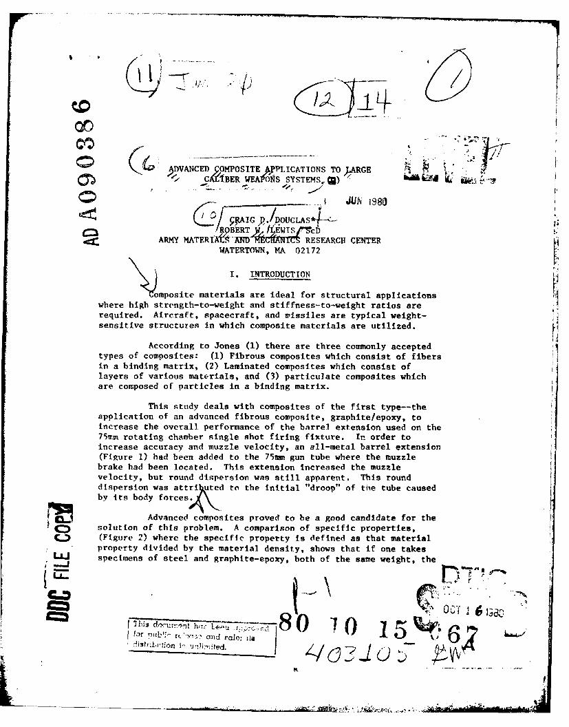
Figure 3 shows the pressure-history experienced by thechamber. A maximum pressure of 55,000 psi is what the chamber ofthe gun sees, but this is not what the muzzle extension must with-stand. The projectile exits at approximately 7-8 milliseconds aftercharge ignition. This means that the end of the tube is exposedonly to atmospheric pressure up to that time. At exit time, thepressure has already decreased to 15,000 psi in the chamber. Also,there is a pressure gradient along the tube such that the muzzlepressure is 80% that of the chamber pressure. The working pressure,
then, seen by the extension is roughly 12,000 psi.
5
4
0 is) 2n ?5 30 35u ime,3 PliESond-S
Figure 3. PRESSURE-HISTORY

DOUGLAS and LEWIS
The internal heat input per round was experimentally deter-mined to be 68 BTU/ft /round (2). This caused a temperature rise of27*F per round at the outer wall of the tube.
After examining these operating conditions, both finiteelement and classical techniques were used to determine exactly howmuch metal was to be removed and how much composite would be added,in order to increase the overall performance while staying withinmaterial property limits.
An orthotropic finite element code ORFE (3) was used topredict the hoop and radial stresses developed during fire. Thiscode is an interactive substructured routine installed on the ANMRCU-1106 computer. For this particular model isoparametric axisym-metric finite elements were used. Figure 4 shows a sample grid usedin the analysis. Classical equations were also developed to analyzethe isotropic cylinder overwrapped with an orthotropic compositesubjected to an internal pressure pulse. This analysis calculatedthe radial stress (Figure 5) and the hoop stress (Figure 6) as afunction of radius.
To verify that the assumption of a static loading casewas valid in the pressure-stress relations, it was necessary todetermine the radial and hoop-type ring frequencies and comparetheir period of oscillation to that of the rise time of the pressurepulse. Calculations showed that these periods of oscillation weresufficiently high so that the Internal pressure pulse would notexcite the system and cause a dynamic loading case.
A thermal analysis was used to determine the axial stressdeveloped during the cure cycle used for the composite, and also todetermine the temperature at the metal/composite interface duringfire. The mismatch of coefficients of thermal expansion of the
metal and the graphite/epoxy was the reason that the thermal studywas needed (hiring cure. Steel has a coefficient of thermal expan-sion that is approximately 6vln/in/*F while that of the compositeIs essentially zero (actually, it is slightly negative in the fiberdirection).
Figure 4. FTNITE-ELEMENT CRID

DOUGLS and LEWIS
12 x10 /
1.0
i/
0.8 "
-/, Composite
04-
/Steel,02
/
0 I I0I 6 I I I I
0 03 0.6 0.9 1.2 1.5 1 8 2 1 2.4 2.7Radius, inch
Figure 5. RADIAL STRESS VERSUS RADIUS
X10 4 /
4
2) Composite
SSteel
•/
/"
0
0 03 0.6 0.9 1.2 1.5 1.8 2.1 2.4 2.6Radius, inch
Figure 6. HOOP STRESS VERSUS RADIUS
i/tel
DOUGLAS and LEWIS
When the liner/mandrel with the uncured composite (ori-ented 0* along the tube axis) is placed in the autoclave and raisedto 350*F, which is the cure temperature of the composite, the exten-sion is virtually stress free. At 350*F the composite system cures,thereby restraining the internal steel mandrel in its elongated
state. When the extension is cooled, it wants to contract by theamount aATL (where a is the coefficient of thermal expansion andL is the length of the tube). It is constrained from doing so,however, by the cured composite thus introducing a residual stressfield. It is this stress field that had to be determined in orderto prevent the composite from buckling during cool-down.
Graphite/epoxy systems tend to lose their structural integ-rity as the operating temperature approaches that of the curetemperature. Hence it is necessary to assure that the operatingtemperature does not exceed 350*F. Figure 7 shows the predicted peaktemperature above ambient as a function of time for a single shot.In this case where the gun was not fired in a repeating mode, thepeak interfacial temperature was determined to be 56*F above that ofthe ambient, well within the operating range of the composite.
56-
48
U32-
24-
0-A
0 20 40 6 80 100 120 140 10 180 200Time, Seconds
Figure 7. PLOT OF WALL TEMPERATURE VERSUS TIME OF EXIT

DOUCLAS and LFWIS
III. FABRICATION
Upon converging on a final liner/randrel design, an originalextension was modified as shown in Figures R and 9. The surface wasthen prepared for interfacial instrumentation and composite applica-tion.
0~4 _0 _
4 'p. 800
Figure R. DIMENSIONS OF LINER/MANDREL
Figure 9. LINER/MANDREL READY FOR COMPOSIT1E APPLICATION
A ten percent solution of hydrochloric acid was used toclean all major dirt and grease left on the part after the machiningproress;. The part was then chucked in a filament winding machinewhlh was used to facilitate part Instrumentation and the hand layupof the graphite-epoxy. The filament winding process was not used atthis point in the fabrication.
A methanol and subsequent acetone rinse were used to cleanthe liner/mandrel itst prior to Instrumenting and composite applica-tion. Two strain gages and a thermocouple were applied to the inter-face. The strain gage orientation was such that longitudinal and hoopstresses ould bo- recorded during fire. The gages and thermocouplewer. then insulate to prevent the graphite/epoxy from electricallyshorting o,,t the gages. The extension was then ready for the firstpraphlife/epoxy applicatfon.
|WA-

DOUGLAS and LEWIS
Because the composite was up to an inch thick toward thebreech end, the graphite/epoxy had to be applied in three separateoperations, with autoclaving between each application; otherwisetoo much resir "bleedout" would have occurred during cure, resultingin a "dry" composite part. These multiple fabrication steps allowedthe application of intracomposite instrumentation to monitor stressesand temperatures through the wall during fire.
After cleaning and instrumentation a film adhesive wasapplied, and three inch wide prepreg tape (HS-3501-6) was layed upunidirectionally along the tube axis. Once the composite was at thedesired thickness (.33 in) for the first application, a bleeder plywas applied, then a burlap bleeder ply, and finally a vacuum bag andgland. The extension was then autoclaved according to the recom-mended cure cycle for the 3501-6 epoxy resin--90 minutes at 120'F,followed by 90 minutes at 350*F. When the autoclave cycle wascompleted the tube was debagged and cleaned. Two more layers ofgraphite/epoxy were applied in the same manner.
To provide field durability and protect the graphite/epoxyfrom the "zippering" effect, or splitting along the fiber axis, thatcould occur with unidirectional composites, a hoop winding of S2glass/epoxy was applied using a filament winding machine. The exten-sion was then post-cured at 370*F for three hours. Figure 10 showsthe composite extension with its final instrumentation ready forfiring tests.
Figure 10. COMPLETED LINER/MANDREL
IV. FIRING TESTS
The firing tests were performed at Ares Corporation,Port Clinton, OH. The gun used was their rotating chamber singleshot test fixture (P&SSTF). Figure 11 shows the composite extensionmounted on the tube.
The firing procedure used was: (1) Ready the RCSSTF inaccordance with pre-firing procedure!; established for proof test ofamwmunition. (2) Install the all-metal barrel extension. (3) Verify
-- ~ . t

DOUGLAS and LEWTIS
barrel bore, breech and barrel Insert, barrel extension, andchamber alignmnent with projectile bore gage. (4) Fire warm-up roundsto insure instrurentation Is operating properly. (5) Verify barrelextension bore alignment wzith bore sight to the center of the target.(6) Fire ten rounds of armor piercing, fin stabilized, discardingsabot (APFSPS) ammunition which has been conditioned at 70*F for atleast eight hours. (7) Repeat steps two through six utilizing thecoimposite barrel extension.
Figure 11. COMPOSITE EXTENSTON READY FOR FIRINC
11. PESULTS
Table I shows the data taken from the round locations onthe tarn'et . The average shot location was significantlv closer toth'. Center of the target for the composite extension In the verticaldirection andl approximaitely the same in the horizontal direction.This .;uggests tha't Iitital barrel droop was indeed less with the4, irp)o.a It eVX t eV 11oS101

DOUGLAS and LEWIS
Table 1. ROUND DISPERSION RESULTS
* FIRING RANGE = 80 METERS
METAL EXTENSION COMPOSITE EXTENSION
VERTICAL HORIZONTAL VERTICAL HORIZONTAL
LOCATION 1.448 MRAD -0.820 MRAD 0.346 MRAD -0.806 MRAD
VARIANCE 0.131 MRAD 0.198 MRAD 0.072 MRAD 0.370 MRAD
Longitudinal and hoop strain data showed a definiteadvantage in using the composite extension. From the longitudinalstrains recorded during the fire, it was found that the compositeextension had a natural frequency that was 22% higher than the metalextension. The damping time (Figure 12) for the composite extensionwas almost 45% lower than that of the metal extension, where thetime to damp, tD, is that time at which the amplitude of vibrationis 0.10 that of the original input. I-
A
tD @ 0. IA
Composite Extension tDavg - 29 msec
Metal Extension tDavg = 51 msec
Figure 12. DAMPING HISTORY
Hoop strain data agreed well with the finite element pre-(fictions. Tt was predicted that the hoop strain during fire wouldreach a value of 870uin/in and the measured value was 990pin/in, anerror of only 11% In the estimate.

DOUGLAS and LEWIS
Thermal data agreed quite well with the predicted value,except for the decay time. The peak temperature predicted was 56F
above ambient, or 106F, approximately sixty seconds after fire.The actual temperature measured was 112*F at 1.25 minutes afterfire. The decay time, however, was almost an order of magnitudegreater than the predicted value.
Erosion data taken by standard star gage techniques showed
no difference between the two extensions.
Finally, the weights of the composite and iretal extension
were 82 and 95 pounds respectively. The metal extension was 16%heavier than the composite2. Note that the weight of the turned-downbarrel was 57 lbs. Thus, 38 pounds of metal were replaced with 25
lbs of graphite/epoxy.
VI. DISCUSSION
The feasibl1ty of using advanced composites In largecaliber weapon systems has been demonstrated. The graphite/epoxybarrel extension was found to be more accurate and lighter than the
all-metal barrel extension. Barrel whip has been reduced signifi-cantly as evidenced by the damping time.
The use of classical and finite element techniques has
proven to be an accurate method when used to predict operating quan-
tities such as the dynamic stresses and strains. Experimental datataken during the firing tests were very close to the analytical. pre-dictions; however, some error was present. The greatest discrepancybetween the predicted and actual values was in the thermal predic-
tions at the metal/composite interface. Although the rise time andpeak temperature were very close to the actual, there was almost nocorrelation in the decay. Classical heat transfer methods predictedan exponential decay that would approach zero within roughly 350seconds, whereas actually the time requiree was 300 sec. Thereason for this difference is thought to arise from the calculation
of the negative exponent in the decay term of the heat balance equa-tion. This term has as part of it, the internal c',nvc-ctive heattransfer coefficient. It Is this quantity that was poorly estimated.It Is interesting to note, however, that one can actually use theexperimentally Treasured thermal data to modify the solution to theheat balance equation in order to obtain the actual heat transfercoefficient. This could then be used in future studies.
Regarding the hoop strain calculations, the actual strain
was only 11% higher than the predicted value. Such a small
- II
t ~

DOUCLAS and LEWIS
difference could be attributed to many things, e.g. a slight dif-ference in material properties with respect to what was used in thecalculations, especially, in the transverse direction of the compos-ite overwrap (which was in the hoop direction of the extension).
These hoop data also verified the assumption that themodel--isotropic cylinder overwrapped with an orthotropic composite--could assume a static loading case. Had there been any dynamic over-shoot (i.e. greater than 25% that of the steady state case) therewould have been a much greater difference between actual and pre-dicted values of hoop strain at the Interface. From these data itcan be concluded that the metal liner could have been made thinnerproviding that the hoop strain at the interface did not exceed thatof the strain-to-failure of the graphite/epoxy in the transversedirection.
Because of the increased stiffness and decreased weight,the natural frequency of the composite extension was higher than thatof the metal. In addition, the damping time of the composite wasless. This could lead to an increased rate of fire in that the com-
posite will have already stopped "whipping" when the metal extensionwould still be in motion.
Probably the most significant aspect of the results wasthe target data. Overall dispersion area for the composite was onethird of that for the metal (Figure 13). The standard deviation ofthe round dispersion in the vertical direction was much less for thecomposite. This fact is attributed to the quicker response of thebarrel as it is straightened from its initial droop when the projec-tile approaches the muzzle and also to the fact that the initialdroop was less because of the lighter weight.
Ranqe = 80 Meters
Metal Extension L Composite Extension
A rea 90.9 in. 2
~A rea 30.7 in.2 "
Figure 13. ROUND DISPERSION AREA

DOUGLAS and LEWIS
One point that must not be overlooked is that the horizon-tal variance was higher for the composite even though the averagehorizontal shot locations were very similar for the two extensions.This phenomenon has not been explained. One suggestion is thatbecause the composite extension was mounted and fired after themetal extension, the test stand might have loosened. It is alsointeresting to note that on the day of the firing of the metalextension there was essentially no wind, whereas on the day that thecomposite extension was tested the winds were gusting up to 15 mph.Whether this point is significant or not has not been determined.
VII. RECOMMENDATIONS
Although vertical round dispersion was significantlydecreased with the current graphite/epoxy system, and the accuracy
of the gun increased, further addition of composites would result instill better overall performance.
At the breech end of the tube, where the highest bending
stresses occur, is where the composite would be most needed. Toimplement this, more detailed analyses would be needed, especiallywith respect to the thermal problems.
Finally, there are other components used in large caliberweapons systems such as suspension components, trails, hydraulicaccumulators etc. that would be candidates for the use of compositematerials, and further investigation could be beneficial in manyaspects such as cost, performance, and weight savings.
VIII. CONCLUSION
An advanced composite barrel extension for a 75mm gun toreplace an all-metal extension has been designed, fabricated andtested. Test firings verified the thermal and structural behaviorpredicted by the computer codes. Round dispersion, muzzle deflec-tions, and "tine-to--damp" were markedly decreased, accompanied by a167 weight savings and an increased natural frequency. The workserves as a base for a complete composite gun barrel to he designed,fabricated and field tested next year.
Weight savings, while modest at 16% in this first design,can be substantial. Taking Into consideration the amount of steelthat was replaced by graphite/epoxy, 37% weight savings resulted.
13

DOUGLAS and LEWIS
Other applications where graphite/epoxy has replaced steel havedemonstrated weight savings up to 70%. This magnitude of weightsavings augurs the development of highly mobile, lightweightvehicles capable of bearing large caliber weapons at a fraction ofcurrent systems weight.
IX. REFERENCES
(1) R. M. Jones, Mechanics of Composite Materials 1975,McGraw-Hill, New York, NY
(2) F. A. Vassallo and W. R. Brown, "Heat Transfer andErosion in the Ares 75mm High Velocity Cannon," Vol 2,Calspan Technical Report, VL-5873-D-1, Buffalo, NY,October 7, 1977.
(3) ORFE Version TII, December 10, 1978, Developed byC. F. Freese at AMMRC, Watertown, MA 02172.
am-- pol