Embed Size (px)
Citation preview

OWNER’S MANUAL, ASSEMBLYand SAFETY INSTRUCTIONS
for Gasoline Hedge Trimmer Attachment
©2009, MANTIS, Division Schiller Grounds Care, Inc.
Shown with Mantis Tiller engine attached.
Shown with Mantis Tiller engine attached.
Single EdgeGasoline
Hedge Trimmer
Attachment
Double EdgeGasoline
Hedge Trimmer
Attachment
AND
®

TABLE OF CONTENTSPage
I. IMPORTANT INFORMATIONA. Introduction ..........................................2B. Special Safety Information ...................2C. Fuel Safety Information........................3
II. SAFETY AND WARNINGSA. Safety Decals.........................................4B. Safety Decal Identification...................4C. General Safety Rules ............................5D.Warnings — Don'ts ...............................5E. Warnings — Do’s ...................................6
III. ASSEMBLY INSTRUCTIONS..........................7 - 8
IV. OPERATION ...................................................9
V.TRIMMING .....................................................10
VI. MAINTENANCEA. Lubrication..........................................10B. Long Term Storage (over 60 days)......11
VII. SERVICEA. Trouble Shooting ................................11B. Service Maintenance Guide ...............11C. Blade Adjustment ...............................12
VIII. PARTS EXPLOSIONS ...........................12 - 16
SERVICE AND WARRANTY POLICY.......................18
I. IMPORTANT INFORMATIONA. INTRODUCTIONOn behalf of everyone at Mantis we wouldlike to thank you for your purchase of aMantis Gasoline Powered Hedge Trimmer.
This professional trimming machine wasdesigned to the highest standards to ensureyou many hours of uninterrupted service.
This manual provides the information necessaryfor safe and efficient operation and service.For your safety, it is critically important thatyou read and understand this entire manualbefore operating your hedge trimmer.
This manual contains different assemblyinstructions for both the Single Edge GasolineHedge Trimmers and the Double EdgeGasoline Hedge Trimmers.Be sure to follow the proper instructions foryour trimmer.
2
WARNING DANGERATTENTION: THIS SYMBOL POINTS OUT OUR
IMPORTANT SAFETY INSTRUCTIONS.
WHEN YOU SEE THIS SYMBOL, HEED IT’S WARNING! STAY ALERT!!
!
!
!
WARNING DANGERTO REDUCE THE POTENTIAL FOR ACCIDENTS,
COMPLY WITH THE SAFETY INSTRUCTIONS IN THIS MANUAL.FAILURE TO COMPLY MAY RESULT IN
SERIOUS PERSONAL INJURY AND OR EQUIPMENTAND PROPERTY DAMAGE.
!!
B. SPECIAL SAFETY INFORMATION

II. SAFETY AND WARNINGS
WARNING DANGERIF TRIMMER IS USED IMPROPERLY OR SAFETY PRECAUTIONS ARE NOT
FOLLOWED, THE USER RISKS SERIOUS INJURY TO THEMSELVES AND OTHERS.READ AND UNDERSTAND THE FOLLOWING BEFORE ATTEMPTING TO OPERATE
THIS HEDGE TRIMMER.
!
3
!
C. Fuel Safety Information
WARNING DANGERHANDLE FUEL WITH CARE, IT IS HIGHLY FLAMMABLE. FUELING A HOT
ENGINE OR NEAR AN IGNITION SOURCE CAN CAUSE A FIRE ANDRESULT IN SERIOUS PERSONAL INJURY AND/OR PROPERTY DAMAGE.
Don’t fuel, refuel or check fuel while smoking ornear an open flame or other ignition source. Stopengine and be sure it is cool before refueling.
Don’t leave the engine running while the trimmeris unattended. Stop engine before putting thetrimmer down or while transporting from oneplace to another.
Don’t start, run or refuel this trimmer indoors, orin an improperly ventilated area as poisonous car-bon monoxide and other gasses are emitted.
Don’t run engine when electrical system causesspark outside the cylinder. During periodicalchecks of the spark plug, keep plug a safe distancefrom cylinder to avoid burning of evaporated fuelfrom cylinder.
Don’t check for spark with spark plug or plug wireremoved and grounded. Use an approved tester.Sparks can ignite fumes.
Don’t crank engine with spark plug removed. Ifthe engine is flooded, open the choke (push chokeknob in) and pull recoil until engine starts. Followinstructions in Tiller manual.
Don’t run engine when the odor of gasoline is pre-sent, or other explosive conditions exist.
Don’t operate the unit if gasoline is spilled. Cleanup spill completely before starting engine.
Don’t operate the unit if there is an accumulationof debris around the muffler, and cooling fins.
Don’t touch hot mufflers, cylinders or cooling finsas contact may cause serious burns.
Don’t refuel indoors or in an improperly ventilatedarea.
Always pull starter cord slowly until resistance isfelt. Then pull cord rapidly to avoid kickback andprevent arm or hand injury.
Always operate engine with spark arrestorinstalled and operating properly. The use of sparkarrestor mufflers is required by law in the state ofCalifornia (Section 4442 of the California PublicResources Code), as well as in other states ormunicipalities. Federal laws apply onfederal lands.
Always handle fuel with care; it is highly flamma-ble. Never add fuel to a machine with arunning or hot engine. Do not inhale fuel fumes asthey are toxic.
Always know how to stop machine quickly in anemergency.
! !
Warning:The Engine Exhaust from this product containschemicals known to the State of California tocause cancer, birth defects or other reproductiveharm.
! !

A. SAFETY DECALSAn important part of the safety system incorporated in this trimmer are the warning and infor-mational decals found on various parts of the trimmer. These decals must be replaced in timedue to abrasion, etc. It is your responsibility to replace the decals when they become hard toread. The part numbers for ordering decals are in Section B, Safety Decal Identification (shownat bottom of this page). The location of these decals is illustrated below.
!
!
P/N 4036Ear and Eye Protection
(Located on your engine.)
P/N 300605Warning Label
4
B. SAFETY DECAL IDENTIFICATION
Single Edge GasolineHedge Trimmers
Double Edge GasolineHedge Trimmers
� READ AND UNDERSTAND OPERATOR’S MANUAL BEFORE USING! KEEP IN A SAFE PLACE!� KEEP BOTH HANDS ON HANDLES AND AWAY FROM BLADES!� KEEP A SURE FOOTING AND NEVER OVERREACH! WHEN REACHING HIGH, STAND ONLY
ON A STABLE SUPPORT, AND NEVER ON THE TOP OF A LADDER!� BLADES COAST AFTER THROTTLE TRIGGER IS RELEASED OR ENGINE IS SWITCHED OFF!� NEVER OPERATE WITHOUT GUARDS, HANDLES, AND SAFETY DEVICES IN PLACE!
WARNING P/N 300605
Important Note: If Safety Decals are not found on your engine, they must be replaced. Call ourCustomer Service department for information at 215-355-9700.
! !
MANTIS LABELP/N 487 MA
MANTIS LABELP/N 487 MA

C. GENERAL SAFETY RULES1. Read and understand the owner’s manual.
Pay particular attention to all sectionsregarding safety.
2. Always keep a firm grip on both handleswhile the blades are moving and/or theengine is running. The right hand graspsthe front handle on double edge hedgetrimmers or the side handle on the singleedge hedge trimmers. The left handgrasps the rear handle.BE AWARE!! The blades coast after
throttle trigger is released or engine isswitched off. Make sure blades have cometo a complete stop and the engine is offbefore releasing a handle.
3. Keep area clear of children, pets, andbystanders.
4. THIS MACHINE CAN CAUSE SERIOUSINJURIES. Read instructions carefully forthe correct handling, preparation, maine-nance, starting and stoping of themachine. Be familiar with all controls andthe proper use of the machine. Pay partic-ular attention to all sections regarding safety.
5. Maintain a firm footing and good balance,do not overreach while trimming. Beforeyou start to trim, check the work area forobstacles that might cause you to losefooting, balance, or control of the machine.While operating the machine, always besure of a safe and secure operating positionespecially when using steps or a ladder.
6. Blades coast after throttle trigger is releasedor engine is switched off.
7. Stop engine before checking, maintenanceor working on the machine.
8. Never operate without guards, handles andsafety devices in place.
9. Never attempt to use an incompletemachine or one fitted with an unauthorizedmodification.
10. To reduce fire hazard, keep engine andsilencer free of debris, leaves, or excessivelubricant.
11. Know how to stop this machine in anemergency.
WARNING DANGERIF TRIMMER IS USED IMPROPERLY OR SAFETY
PRECAUTIONS ARE NOT FOLLOWED, THE USERSRISK SERIOUS INJURY TO THEMSELVES
AND OTHERS.
READ AND UNDERSTAND THE FOLLOWINGBEFORE ATTEMPTING TO OPERATE
THIS HEDGE TRIMMER.
!
! !WARNING DANGER
THE BLADES COAST AFTER THROTTLETRIGGER IS RELEASED OR ENGINE ISSWITCHED OFF. MAKE SURE BLADESHAVE COME TO A COMPLETE STOP
AND ENGINE IS OFF BEFORERELEASING A HANDLE
! !
5
D. WARNINGS — DON’TSDon’t use trimmer with one hand; keep bothhands on handles with fingers and thumbsencircling the handles, while blades are mov-ing and engine is running.
Don’t overreach or stand on unstable support.Do not stand on the top of a ladder while trim-ming. Use proper equipment for reachinghigher heights. Keep a good footing at alltimes.
Don’t ever grasp cutting blades for any reason.
Don’t attempt to clear cut material whileblades are moving, and the engine is running.Never try to remove jammed material before
switching the engine off and making sure theblades have stopped completely.
Don’t override safety features.
Don’t allow children or incapable people tooperate this trimmer.
Don’t operate this hedge trimmer while underthe influence of alcohol or drugs.
Don’t attempt to repair this hedge trimmer.Have repairs made by a qualified dealer orrepairman. See that only original Mantisparts are used.
Don’t operate the machine with a damaged orexcessively worn cutting device.
!

E. WARNINGS — DO’SAlways read and follow all instructions.
Always stay alert. Watch what you are doingand use common sense. Do not operate unitwhen fatigued.
Always dress properly. Do not wear looseclothing or jewelry, they might get caught inmoving parts. Use sturdy proper fitting, non-slip gloves. Gloves reduce the transmission ofvibration to your hands. Prolonged exposure tovibration can cause numbness and other ail-ments. Wear non-skid footwear to ensuresecure and proper footing.
Always wear ear and eye protection. Eye pro-tection must meet ANSI Z 87.1. To avoidhearing damage we recommend hearing pro-tection be worn whenever using the equip-ment.
Always keep both hands on both handleswhen trimmer is running. Severe injuries canresult if you try to use the hedge trimmer withonly one hand or with an insecure grip.
Always keep children, pets, and incapable per-sons away.
Always use trimmer properly. Cut only types
and size of growth described in the Trimmingsection of this manual. Overloading or abus-ing your hedge trimmer can cause prematurefailure and can result in injury. Use commonsense.
Always keep a safe distance between two ormore operators when working togethersimultaneously.
Always inspect your unit before each use andensure that all handles, guards, safety devicesand fasteners are secure, operating, and inplace.
Always maintain and examine your trimmerwith care. Follow maintenance instructionsgiven in manual.
Always store trimmer in a sheltered area (a dryplace) not accessible to children. The hedgetrimmer as well as fuel should not be stored ina house.
Always be aware of power lines.
Always stop the engine before adjusting theworking position of the cutting device.
Always make sure that the cutting blades arein the correct working position that you wantbefore starting the engine.
!
6
IImmppoorrttaanntt:: Always follow the Engine and Fuel Warnings found inyour Tiller Manual.
If you don’t have your Tiller Manual, call our Customer ServiceDepartment at 1-800-366-6268 to purchase a replacement or visitwww.mantis.com to download a copy.

III. ASSEMBLY INSTRUCTIONS
1. Remove the cutter bar assembly, throttle assembly with side handle, and hard-ware bag from their boxes.
WARNING DANGERBLADES ARE EXTREMELY SHARP. TO AVOIDINJURY WHEN UNPACKING AND ASSEMBLING
THE HEDGE TRIMMER, DO NOT GRASP THE BLADES.
!!
7
The hardware bag consists of the followingitems:P/N Description Qty
972 1/4-20 Lock Nut 2300102 Handle Support Channel 2300113 Spacer Tube 2300111 Shock Absorber 4300112 Support Plate 1300505 1/4-20 x 2 1/2 Bolt 23036-B 1/4-28 Flange Locknut 2
2. Place the front side handle over the two1/4-28 studs protruding from the frame bar infront of the gear housing. The handle gripmust be pointing away from the cuttingblades as illustrated below. On Model2230SAH use the set of studs which places
WARNING DANGERIMPROPER ASSEMBLY OF THIS
TRIMMER CAN RESULT INSERIOUS INJURY.
MAKE SURE TO FOLLOW ALLINSTRUCTIONS CAREFULLY.
IF YOU HAVE ANY QUESTIONS CALL1-800-366-6268 AND ASK FOR SERVICEOR FOR THE NAME OF YOUR LOCAL
MANTIS DEALER.
!!
B. SINGLE EDGE GASOLINE HEDGE TRIMMERS (CAT # 2230SAM)
A. DOUBLE EDGE GASOLINE HEDGETRIMMERS (CAT # 2224DAHM)
NO HEDGE TRIMMER ATTACHMENT ASSEMBLYIS NEEDED.
To attach your engine, see sections B 3, 4, 5, 6, 7, 8.
the handle in the most comfortable positionfor you. Place the thread protectors over theset of studs that you choose not to use at thistime to protect the threads. Secure the handlein place using two 1/4-28 flange locking nutsprovided. The nuts should be tightenedenough to keep the handle from moving butnot so tight as to crush the plastic.
3. To remove the engine from your Mantistiller you will need to identify which throttlecable connection you have. There are two dif-ferent styles.
To remove the engine if your tiller has theconnection shown in picture 1, (SV4 Enginemodels only). First remove the air cleanercover and air filter.
If your tiller has an engine that looks like inpicture 2, just follow the written instructions.

8
Detach the throttle cable at the carburetor byloosening the two 10mm nuts on the thread-ed end
Slide the cable out and down to unhook itfrom the swivel. Separate the ground wire atthe wire connection, which is approximately3" from the engine.
Loosen the screw at the very bottom of theengine, just above where the handles areattached to the tiller. Then just lift theengine up.
4. First, fasten the black ground wire from thehandle assembly to the ground screw. Usethe screw that is located on the bottom of theengine, closest and to the right of the fuel tank.This ground wire has an eyelet connection.Therefore, when you want to remove theengine from the trimmer, just separate thewire connection. It is not necessary tounscrew the ground screw. See illustration.
5. Install the engine to the hedge trimmerby first aligning the hex drive on the trimmergear housing with the hex socket in the
engine. Slide the engine over the 1” diameterstem containing the hex drive on the gearhousing until it is seated all the way down onthe gear housing (see illustration below).
6. Press shock absorbers into sockets on thegear housing followed by the spacer tubes.Secure handle and tubing support channelswith the 1/4-20 hex bolts and locking nutssupplied. (See illustration at the top right)
7. Plug the red wire from the engine into theswitch wire (rectangular flat connector) fromthe handle assembly.
8. Feed the throttle cable up between the fueltank and the carburetor. Locate the metal“button” on the triangle. This is the swivel.The large end of the throttle cable must beinside the slot in this swivel. (See Picture 3.)Separate the two nuts and washers and slidethem onto the engine. (See Picture 2.) Adjustthe nuts so the triangle touches the carburetorcase when you squeeze the trigger and hits theidle screw when the trigger is released. (Picture2.) Tighten the two nuts until they are snugusing a 10mm or an adjustable wrench.Throttle movement should be smooth andunobstructed. Align the engine and tighten themounting screw. Reinstall the filter and filtercover.
ATTACHING THE ENGINE TO EITHER THE SINGLEEDGE OR DOUBLE EDGE TRIMMER ATTACHMENT
Throttle Cable
Swivel
10mm nuts

9
WARNING DANGERTHE OPERATOR OF THIS HEDGE TRIMMER IS RESPONSIBLE FOR
ACCIDENTS OR HAZARDS OCCURRING TO HIMSELF, OTHER PEOPLE OR THEIR PROPERTY.
WARNING DANGERAVOID ACCIDENTAL BLADE
ENGAGEMENT.
DO NOT SQUEEZE THE THROTTLETRIGGER WHEN STARTING.
MAINTAIN PROPER IDLE SPEEDADJUSTMENT (2200-2300 RPM)
! !
! !
STARTING THE ENGINE WITH THE TRIMMERATTACHMENT11.. Place the hedge trimmer flat on theground, or other stable surface.
22.. Slide the ignition switch to the STARTposition.
33.. Proceed with engine starting instructions found in your Tiller Manual.
STOPPING THE ENGINE WITH THE TRIMMERATTACHMENT11.. Release the throttle trigger and allowengine to idle.
22. Slide ignition switch to the STOP position.
33. Make sure blades have come to a com-plete stop before releasing either handle.
WARNING DANGERIF ENGINE DOES NOT STOP WHEN
SWITCH IS PUT IN THE STOP POSITION, RELEASE THE THROTTLETRIGGER, ALLOW ENGINE TO IDLE.
PUT THE TRIMMER DOWN, ANDPULL THE CHOKE BUTTON OUT TOCOLD START (CLOSED) POSITION.
CHECK AND REPLACEIGNITION SWITCH BEFORESTARTING ENGINE AGAIN.
!!
CHECK YOUR TILLER MANUAL FOR PROPER OPERATING INSTRUCTIONS FOR THE ENGINE
IV OPERATION
Single edge hedgetrimmer attachments
Double edge hedgetrimmer attachments

11.. WARNING! Read and follow all safetyinstructions in the manual before attempting touse this trimmer.
22.. Only after you are familiar with yourhedge trimmer and all of its controls and thefunctions should you start the engine.
33.. Once the engine is started grasp the han-dles securely, the left hand should grasp therear handle.The right hand should grasp thefront (on the double edge hedge trimmer) orside (on the single edge hedge trimmer) handle.
44.. Squeeze the throttle to accelerate theengine and engage the blades.
55.. Tilt the trimmer so the cutting teeth areangled slightly toward the hedge or shrub and
VI. MAINTENANCE A. LUBRICATION11.. A few drops of a light #10 oil should beplaced on the back edge of each blade guard, orprotective comb, at each adjusting screwapproximately after every 4 hours of normaloperation.
22.. To obtain trouble free trimming, it is necessary to keep the blades lubricated andclean. The gum that collects and builds up onthe blades can be removed with a 50-50 mixture of kerosene and #10 oil. As petroleumproducts can shorten the life of some plasticsit is necessary to remove excess oil-kerosenemixture from the plastic parts.
33.. When blades are replaced, or any othertime that the bottom cover plate is removed,the grease level should be checked for properamount (approximately 3/4 full in the area ofthe gears) and a new gasket should be used toinsure proper seating of the cover plate. Useonly Lubrico M3-3K-9K grease in the gearhousing.
V. TRIMMING
WARNING DANGERBLADES COAST AFTER RELEASINGTHROTTLE OR STOPPING ENGINE.
KEEP A FIRM GRIP WITH BOTHHANDS ON BOTH HANDLES WHILE
BLADES ARE MOVING AND/ORENGINE IS RUNNING.
DO NOT STAND ON THE TOP OF ALADDER WHILE TRIMMING.
MAKE SURE YOUR LADDER OROTHER SUPPORT IS STABLE AND ON
FIRM GROUND.
KEEP A SURE FOOTING.DO NOT OVERREACH.
IF YOUR TRIMMER BECOMESJAMMED RELEASE THROTTLE ANDSTOP ENGINE. MMAAKKEE SSUURREE BBLLAADDEESS
HHAAVVEE SSTTOOPPPPEEDD CCOOMMPPLLEETTEELLYY..REMOVE THE SPARK PLUG CAP FROM
THE SPARK PLUG, THEM REMOVETHE OBSTRUCTION.
! !
10
Misuse of this Hedge Trimmer will void thewarranty.ie: Cutting hedges or shrubs over 1" in diame-ter or foreign objects such as wires, rocks, orfences. Before trimming, check work area forforeign objects such as wires, cords, glass,fences, or rocks. Be sure to remove any foreign object from work area. Failure to properly maintain this hedge trimmer willvoid the warranty.
proceed to cut. Use overlapping sweepingmotions away from your body to achieve asafe and even cut.
66.. These units are designed tocut any type of hedge orshrub; however,
THICKNESS OFCUT SHOULD NOT EXCEED 1 INCH IN DIAMETER.
1"
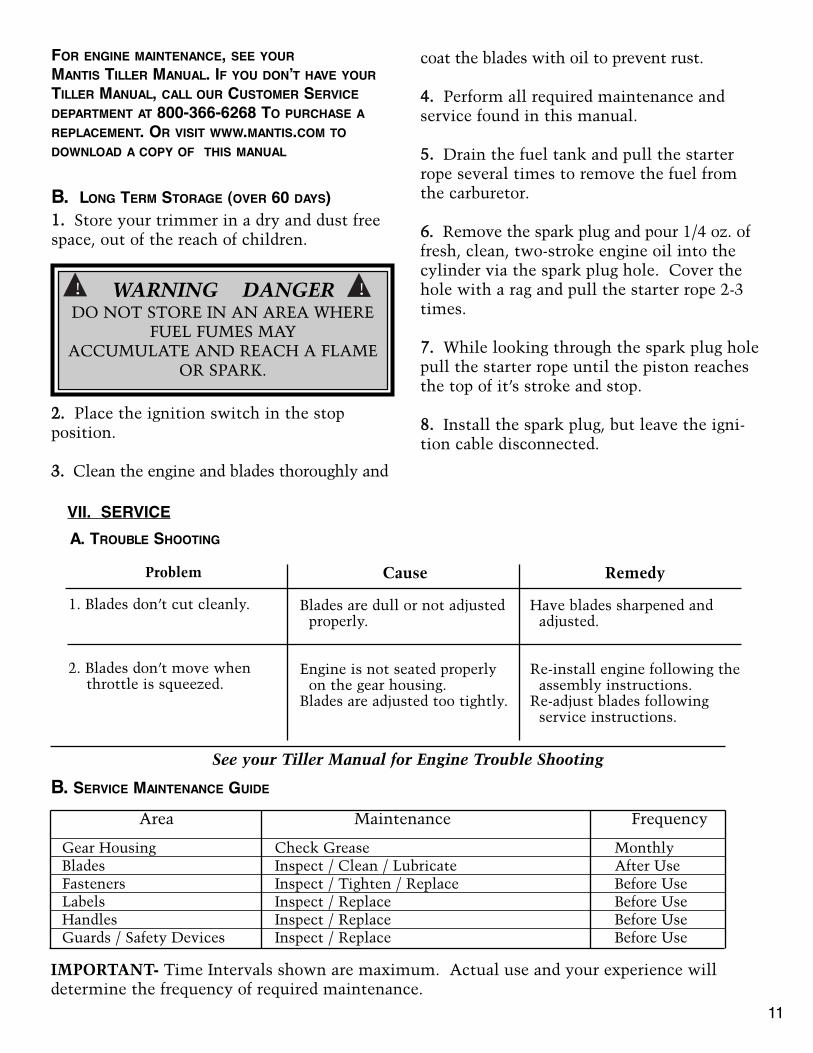
B. LONG TERM STORAGE (OVER 60 DAYS)11.. Store your trimmer in a dry and dust freespace, out of the reach of children.
22.. Place the ignition switch in the stop position.
33.. Clean the engine and blades thoroughly and
WARNING DANGERDO NOT STORE IN AN AREA WHERE
FUEL FUMES MAY ACCUMULATE AND REACH A FLAME
OR SPARK.
! !
11
FOR ENGINE MAINTENANCE, SEE YOURMANTIS TILLER MANUAL. IF YOU DON’T HAVE YOURTILLER MANUAL, CALL OUR CUSTOMER SERVICEDEPARTMENT AT 800-366-6268 TO PURCHASE AREPLACEMENT. OR VISIT WWW.MANTIS.COM TODOWNLOAD A COPY OF THIS MANUAL
coat the blades with oil to prevent rust.
44.. Perform all required maintenance and service found in this manual.
55.. Drain the fuel tank and pull the starterrope several times to remove the fuel fromthe carburetor.
66.. Remove the spark plug and pour 1/4 oz. offresh, clean, two-stroke engine oil into thecylinder via the spark plug hole. Cover thehole with a rag and pull the starter rope 2-3times.
77.. While looking through the spark plug holepull the starter rope until the piston reachesthe top of it’s stroke and stop.
88.. Install the spark plug, but leave the igni-tion cable disconnected.
VII. SERVICEA. TROUBLE SHOOTING
Problem
1. Blades don’t cut cleanly.
2. Blades don’t move when throttle is squeezed.
Remedy
Have blades sharpened and adjusted.
Re-install engine following theassembly instructions.
Re-adjust blades followingservice instructions.
Cause
Blades are dull or not adjustedproperly.
Engine is not seated properlyon the gear housing.
Blades are adjusted too tightly.
B. SERVICE MAINTENANCE GUIDE
Area
Gear HousingBladesFastenersLabelsHandlesGuards / Safety Devices
Maintenance
Check GreaseInspect / Clean / LubricateInspect / Tighten / ReplaceInspect / ReplaceInspect / ReplaceInspect / Replace
Frequency
MonthlyAfter UseBefore UseBefore UseBefore UseBefore Use
IMPORTANT- Time Intervals shown are maximum. Actual use and your experience will determine the frequency of required maintenance.
See your Tiller Manual for Engine Trouble Shooting

VIII. PARTS EXPLOSIONSGEAR HOUSING ASSEMBLY
The care and adjustment of the blades is mostimportant to the efficient operation of thetrimmer and especially to the long life of theengine.
1. Place the trimmer in vise clamping on theframe bar. Be careful! Blades are sharp!
2. Using a 7/16” wrench, loosen all bladelocknuts and unscrew the large head screwsby two turns.
3. Starting with the screw nearest the gearhousing, tighten the screw until the bladeguard of the Single Edge trimmer or the pro-tective comb of the Double Edge trimmer canjust be moved with finger pressure and a.0015” (1 1/2 thou.) feeler blade just slipsunder the blade guard or comb. Tighten thelocknuts while holding the screw stationary inits correctly adjusted position.
4. Repeat Step 3 on the screws in turn untilall are correctly adjusted.
C. BLADE ADJUSTMENT
12
NOTE: CORRECT BLADE ADJUSTMENT CAN ONLY BEACHIEVED ON CLEAN, OILED BLADES.
KeyNo. Part No. Description Qty.
1 371 Pinion 12 375 Washer 13 374 Upper Bushing 14 300000 Gear Hsg Assem. (inc. Key No. 3, 6, 12) 15 D16-56F Wear Plate 16 16-61 Eccentric Shaft 17 372 Eccentric Gear 18 314 Felt 19 319 Gasket 110 316 Cover Plate 111 16-81 6-32 x 5/16 Screw Pack 112 16-80 Cover Plate Pin 113 373 Lower Bushing 1
Single Edge Trimmer
Double Edge Trimmer
WARNING DANGERSWITCH OFF THE ENGINE BEFORELUBRICATING OR ADJUSTING THE
BLADES
! !

KeyNo. P
art No. D
escription Qty.
1300000
Gear H
ousing Assem
bly1
216-54B
1/4-28 Whiz F
lange Locknut 7
3300300
Fram
e Bar B
race1
4300200
Side H
andle1
5300201
Grip
16
30031030" F
rame B
ar 1
730-2
30" Inside Blade
1
KeyNo.
Part N
o. Description
Qty.
830-1
30" Outside B
lade 1
916-93
Blade G
uard5
1016-54A
Large Head P
hillips Screw
4
11300504
Large Head S
crew 1/4-28 x 7/8
112
16-65Connecting R
od Spacer
113
16-64Connecting R
od1
14300316
Thread P
rotector 2
153036-B
1/4-28 Flange Locknut
2
CUTTING BAR AND SIDE HANDLE ASSEMBLYSingle Edge Trimmers
13

REAR HANDLE ASSEMBLYSingle Edge Trimmers
KeyNo. P
art No. D
escription Qty.
1300101
Handle
12
300103Grip (S
et)1
3300117
Switch P
late1
4300122
Trigger S
et1
5300108
Trigger \ Lockout S
prings1
6- - - -
- - - - - --
7300120
Switch/W
ith Leads 1
8973
10-32 Lock Nut
19
300116Conduit
111
30050310-32 x 1 1/4" M
achine Screw
112
9721/4-20 Lock N
ut2
13300102
Handle S
upport Channel
2
KeyNo. P
art No. D
escription Qty.
14300113
Spacer
215
300111Shock A
bsorber4
16300112
Support P
late1
17300505
1/4-20 x 2 1/2" Bolt
218
3005026MM Star Lock W
asher2
19300500
6MM Nut
220
300115Throttle C
able1
21300000
Gear H
ousing Assem
bly1
22300511
7/8" Phillips P
an Head S
crew4
23300109
Switch C
ap1
24300118
Cable T
ie1
25376-1
Handle E
nd Cap
126
300121Eyelet S
pade Term
inal1
14

KeyNo. P
art No. D
escription Qty.
2300115
Throttle C
able1
3300500
6MM Nut
24
3005026MM External S
tar Lockwasher
25
300119Conduit
16
16-54B1/4 - 28 W
hiz Flange Locknut
77
30030824" D
.E. Fram
e Bar w
/Studs (for m
odel 2224DAH)
17
30031230" D
.E. Fram
e Bar w
/Studs
18
24-2D24" D
.E. Inside B
lade 1
830-2D
30" D.E Inside B
lade1
924-1D
24" D.E. Outside B
lade 1
930-1D
30" D.E. Outside B
lade1
KeyNo.
Part N
o. Description
Qty.
1024-42
24" Protective C
omb
111
16-54ALarge H
ead Phillips S
crew
312
3005047/8" Large H
ead Phillips S
crew1
1316-65
Connecting R
od Spacer
114
16-64Connecting R
od1
15300512
1/4 - 20 x 2 1/4 Bolt
216
300112Support P
late3
17300403
Shock A
bsorber8
18300000
Gear H
ousing Assem
bly1
19300113
Spacer T
ube4
20972
1/4 - 20 Locknut2
21300300
Fram
e Bar B
race1
CUTTING BAR ASSEMBLYDouble Edge Trimmers
15

HANDLE ASSEMBLYDouble Edge Trimmers
KeyNo. P
art No. D
escription Qty.
1300511
7/8" Phillips P
an Head S
crew8
2300113
Spacer T
ube4
3300403
Shock A
bsorber8
4328
1/4" Flat W
asher2
5300506
1/4-28 x 1 5/8 Hex H
ead Bolt
26
30051010-32 x 4 H
ex Head B
olt1
7300508
#10 Flat W
asher2
8300400
Grip S
et1
9300507
10-32 x 5 1/2 Hex H
ead Bolt
1
KeyNo.
Part N
o. Description
Qty.
10300405
Hand G
uard1
11300404
Front H
andle1
12300120
Switch W
ith Leads1
13300117
Switch P
late1
14300122
Trigger S
et1
15300108
Trigger/Lockout S
pring1
16- - - - -
- - - - - - - --
17300109
Switch C
ap1
18973
10-32 Locknut2
19300121
Eyelet S
pade Term
inal1
16

Name Phone: Day ( )
Address Evening ( )
City State Zip Customer No:(not necessary but helpful)
Product(s) being returned
What do you want us to do? � Repair � Refund � Other
If you are requesting a refund, please tell us why:� Product is different than I expected � Not satisfied with performance
� Not satisfied with quality � Other
For repair service, please continue on other side of this form.
�
Return Information
If you are having any trouble with anyMantis product, please call us. Ask forCustomer Service. Usually, we cansolve most problems over the phone.
If we are unable to solve your problemand you still want to return the attach-ment...
Always call first — 1-800-366-6268
to receive your Return Authorizationnumber.
Please have the following informationwhen you call:
1. Date of purchase
2. Date attachment was first used
3. Customer number, if available
IF YOU NEED TORETURN A PRODUCTVery few customers ever need to returna Mantis product, but just in case youhave to...here are some simple instruc-tions that will help us serve you quickerand better.
Please clean the product if it has beenused. (Remove dirt from attachment).
Give us as much information as possi-ble, so that we can help you as quicklyas possible.
Please provide the following information and send this completed form with your product.
17

If you are returning a product for repair or for a repair cost estimate, please tell uswhat appears to be broken or what performance needs to be improved:
FOR REPAIR or REFUNDS:MMAANNTTIISS
Disassemble and pack your product in the original shipping carton or any other strong corrugated box. Ship the returned product, prepaid, by UPS or USPS (Post Office).
©Schiller Grounds Care, Inc, 2009P/N 300703 08-09
For additional information on the care and use of any Mantis attachment, please call our Service Department at 800-366-6268
Warning: The Engine Exhaust from this product contains chemicals known to theState of California to cause cancer, birth defects or other reproductive harm.!
�
ATTACHMENT LIMITED SERVICE & WARRANTY POLICY
The Mantis Tiller and its attachments are guaranteed against defects in material and workmanship for aperiod of TWO YEARS FROM DATE OF PURCHASE. All tines for the tiller are guaranteed for life againstbreakage. Any Mantis products or parts found to be defective within the warranty period are to be returned toour factory at Southampton, PA
Transportation charges on parts and units submitted for repair or replacement under this warranty must bepaid by the purchaser.
THIS WARRANTY shall not be effective if the product has been the subject of misuse, negligence or accidentor if the product has been repaired or altered outside of our Southampton factory in any respect whichaffects its condition or operation.
Mantis shall not be liable for any special indirect or consequential damages arising from defective equipment.Any implied warranty, including merchantability or fitness for a particular purpose, shall not extendbeyond the written warranty period.
®
1028 Street Road • Southampton, PA 18966(215) 355-9700 • 1-800-366-6268
1028 Street RoadSouthampton, PA 18966When shipping through the Post Office, be sure to insure your product
for replacement value and ship certified.