Embed Size (px)
Citation preview

' ! ' �
•
' ' '
GEH-5687 Installation Manual
GE AKD-8 Low Voltage Switchgear
MOD-3
Installation And Maintenance Instructions
www . El
ectric
alPar
tMan
uals
. com
AKD-8 Low-voltage Switchgear Table of Contents
CONTENTS
Description Page Description ------------------------------------� Page
S ECTI ON 1-l ntroduction 4 SECTI ON IV- (Cont'd) 1 . 1 General I nformation . . . . . . . . . . . . . . . . . . . . . . . . . . . . . 4 1 .2 Instruction Book Arrangement . . . . . . . . . . . . . . . . . . . . 4 1 .3 Related Publ ications . . . . . . . . . . . . . . . . . . . . . . . . . . . . . 5
C. Foundation Preparation . . . . . .... .. . . .. .. ... .. . 35 C-1 . Indoor Equipment ... . . .. . ... . . .. .. .. ... . 35 C-2. Outdoor Equipment .. . . ..... . . . . . .. . . . .. 38
S ECTIO N 11-Receiving, Handl ing, and 4.2 Assembly and I nstal lat ion of Switchgear
Equipment . . ... ... . . .. .... .. . . . .. . . . . . . .. . .. . . .. 39 Storage . . . . . . . .. . . .. .. .. . .. . . . . . . 6 A. General Requ i rements . . ...... . . . . . . . . . . .. . . .. 39
2.1 Receiving . . . . . . . . . . . . . . . . . . . . . . . . . . . . . . . . . . . . . . . 6 B. Detai led Assembly and I nstal lation I nstructions . 39 A. Equipment Packages . . . . . . . . . . . . . . . . . . . . . . . . . 6 B. I nspecting for Damage . . . .. . . .. . . . . . . . . . . . . . . . 6 C. F i l ing a Claim . . . . . . . . . . . . . . . . . . . . . . . . . . . . . . . . 6
B-1 . Indoor Equipment .. . ... .... .. .. . .. . . .. . . 39 B-2. Outdoor Equipment ..... . . .. .. .. ... . . . .. 46
C. Anchori ng Switchgear Equipment .. . .. ... . . ... 47
2.2 Hand l ing . . . . . . . . . . . . . . . . . . . . . . . . . . . . . . . . . . . . . . . . 7 C-1 . Indoor Equipment . .. . . . ..... . . .. . . . . . .. . 48
A. Lifti ng . . . . . . . . . . . . . . . . . . . . . . . . . . . . . . . . . . . . . . . 7 B. Rol lers . . . . . . . . . . . . . . . . . . . . . . . . . . . . . . . . . . . . . . 9 C. Fork l i fts . . . . . . . . . . . . . . . . . . . . . . . . . . . . . . . . . . . . . 9 D. Jacks . . . . . . . .. . . .. . . . .. . .... .... . . . .. . . . .... . 1 1
C-2. Outdoor Equipment ... . . . . . . . ... . . ... ... 49 D. Busway Connections . .. .. . .. .. .. . . ... . . .. . ... 49 E. Control Wire Connections .. . ... ..... . .. . . . .. .. 49 F. Power Cable Connections . . .. . . . . .. .. . . .... . . . 50
2.3 Storage . . . . . . . . . . . . . . . . . . . . . . . . . . . . . . . . . . . . . . . . . 1 2 G . Relays and Control Devices ... . ... . . . . . .. . . . . . 50 A. Switchgear . . . . . . . . . . . . . . . . . . . . . . . . . . . . . . . . . . 1 2 H. Breaker Hoist .... ... . . .. .... .. .... .. ... ... .. . 51
B . Circuit Breakers ... . . . ... .. . .... ... . .. . . . .... . 1 2 H-1 . Indoor Equipment .. ... . . .. . .. . . .. .... .. . 51
S ECTI O N I l l- Description . . . .. .. . .. . ... . . . . . . 1 3 H-2. Outdoor Equipment . .. . . . . . . . . .... . . . . .. 53
I . F inal Inspection . . . . . . . . . . . . . . . . . . . . . . . . . . . . . 53 3 . 1 3.2 3.3 3.4 3.5 3.6
3.7
3.8 3.9
3 . 1 0
3 . 1 1 3 . 1 2 3. 1 3
General .. . ... . .. . . .. . .. . . ... . ... . .. . ... . .. . .. .. . 1 3 Summary Description · · · · · · · · · · · · · · · · · · · · · · · · · · · · 1
13
6 SECTION V-l nstal l ing and Removing
Compartment Area . . .. ... . . . .. .. .... ... . .... . · . . . c· "t 8 k I nstrument Tray .... . . . .. . ..... .... ... .. .. .. .. . ... 1 6 lrCUI rea e rs .. . ..... . . . .. . · 54
B reaker Compartment . . . . . ... . . .. . . .. .... . ... . . . 1 8 5 . 1 General . . . . . . . ... . . . .. . . . ... . . .. . . .. . . .... . . . ... . 54 Circu it Breakers ... . .... ... . ... . . . .. . .. . ... .. . . . . 24 A. Inspection and Preparation of C ircu it Breakers . 54 A. AKR-30S Breaker . . . . . . . . . . . . . . . . . . . . . . . . . . . . . . 24 B. Circu i t Breaker Instal lation . .. . .. . . ..... .... . . . 54 B. AKRU-30S Fused Breaker . . . . . . . . . . . . . . . . . . . . . . 24 C. Rejection Feature . .. . . . . . . .. . . .. . . . . . .. .. .. . . 54 C. AKR-30 Breaker . . . . . . . . . . . . . . . . . . . . . . . . . . . . . . . 24 5.2 Instal l i ng the AKR Circu it Breakers .. . .. . . .. . . .. . .. 55 D. AKRU-30 Fused Breaker . . . . . . . . . . . . . . . . . . . . . . . 24 A. Prior to Instal lation .. . . .... .. . . . . . . .. . . . .. . . . . 55 E . AKR-50 Breaker . . . . . . . . . . . . . . . . . . . . . . . . . . . . . . . 25 B. Instal lation Procedures .. ... . .. ... .. .. . . .. . . . . 55 F. AKRU-50 Fused Breaker . . . . . . . . . . . . . . . . . . . . . . . 25 5.3 Mount ing the AKR-75/1 00 Circu it Breaker on G . AKRT-50 Breaker . . . . . . . . . . . . . . . . . . . .. . . . . . . . . . 25 the Drawout Mechanism .. ... . .. . . . . . . ... . . . . . .. . 58 H. AKR-75 Breaker . . . . . . . . . . . . . . . . . . . . . . . . . . . . . . . 25 5.4 Removi ng the AKR-30/50/T50 and AKRU-30/50 I. AKR-1 00 Breaker . . . . . . . . . . . . . . . . . . .. . . . . . . . . . . 25 Circuit Breakers .. . . . . . . . ... .. . .... -�: . . .. .. . . . . .. 59 Fuse Rol lout Elements .. . . . . . . . . . . . . . . . . . . . . . . . . . 25 5.5 Removing the AKR-75/1 00 C i rcuit Breakers . .. . . . . . 59 A. AKR-75 Fuse Rol lout Carriage . . . .. .. .... . ... . . 25 5.6 Instal l i ng and Removi ng AKRU-30/50 Fused B. AKR-1 00 Fuse Rol lout Carriage . . . . . . .. .. . . . . .. 25 Circu it Breakers . . . . . . . . .. . ..... .. . . . . . . .. . . .. .. . 60
Compartments for Future B reakers .. . . . . . . .. .... .. 26 5.7 Instal l i ng Fuses to AKRU-30/50 C i rcu it Breakers . . .. 60
Auxi l iary/Transition Sections . . . . . . . . . . . .. ... . . . . . 26 5.8 Instal l i ng and Removing Fuse Rol lout Elements
Bus Area . . . . .. . . . . . . .. . . . . . ... .. .. . .. . . . . .. . . .. . 28 (FR0)-30-inch Wide Compartments . . . . . . .. . . .. . . 62
A. Busing System . . . . . . . . . . . . . . . . . . .. .. . . . . .... . 29 B. INSUL-BAR Bus I nsu lation System ... .. .. .. . . . . 30 Feeder Cable and Busway Compartment . . . .. . . . . . . 32
SECTION VI-Testi ng and I n spection . . .. . . 64 6 . 1 General . . . .. . . . .. . . . . . . . . . . . . . .. ... . . . . . . . ... ... 64
Ground Bus . . . . . . .. . . . . . . . . . . . . . . .. . . . . . . . . . ... . 33 AKD-8 Outdoor Switchgear . . . . . . . . . .. . . . . . . . . .... 33
6 .2 Key Interlocks . . . . . .. . . . . ... . . . .. . . .. . . . . . .. . . . .. 64 6.3 Breaker Operation Test . .. . . .. . . . ... . . ... .. . . . . . . 64
SECTION IV-Equipment I n stal lation . . . .. . 35 6.4 MicroVersaTrip'M RMS-9 Programmer . . . . . . . . . . . . . . . 64 6.5 Epic MicroVersaTrip'M Programmer . . . . . . . . . . . . . . . .. 65
4 . 1 General . . . . . . . . . . . .. . . . . . . . . . . . . . . . . . . . . . . . . . .. . 35 6.6 Final Steps to Be Taken Before Energizing A. Site Loc.at ion . . . . . . . . .. . .. . . . . . . . . .. .. .. . . . . . . 35 Equipment . . . . . . . . . . . . . . . . . . . . . . . . . . . . . . . . . . . . . . . 65 B. Foundation Req u i rements . . . . . . . . . .. . . . . . . .. . 35
2 www . El
ectric
alPar
tMan
uals
. com

Table of Contents
CO NTENTS
Description Page Description ------------------------------�� Page
SECTION VI I-Operati ng the Switchgear 66
7.1 C ircu it Breaker Operation . . . . . . . . . . . . . . . . . . . . . . . . 66 A. General . . . . . . . . . . . . . . . . . . . . . . . . . . . . . . . . . . . . . . 66 B . Manual ly Operated Breakers . . . . . . . . . . . . . . . . . . 66
B-1 . Closing Manual ly Operated AKR Circuit Breakers . . . . . . . . . . . . . . . . . . . . . . . . . . . . . . . 66
B-2. Tripping Manual ly Operated AKR Ci rcuit Breakers . . . . . . . . . . . . . . . . . . . . . . . . . . . . . . . 66
C. Electrical ly Operated Breakers . . . . . . . . . . . . . . . . 66 D. E lectrical Tri pping of AKR Breakers . . . . . . . . . . . . 66
7 .2 Circuit B reaker Drawout Operation . . . . . . . . . . . . . . . . 66 A. Breaker Positions . . . . . . . . . . . . . . . . . . . . . . . . . . . . 66 B . Drawout Operation . . . . . . . . . . . . . . . . . . . . . . . . . . . 67
7.3 Front Doors . . . . . . . . . . . . . . . . . . . . . . . . . . . . . . . . . . . . . 67 A. Operation . . . . . . . . . . . . . . . . . . . . . . . . . . . . . . . . . . . . 67 B . Removal and Instal lation . . . . . . . . . . . . . . . . . . . . . . 67
B-1 . Door Removal . . . . . . . . . . . . . . . . . . . . . . . . . . . 67 B-2. Door I nstal lation . . . . . . . . . . . . . . . . . . . . . . . . 67
7.4 AKD-8 Switchgear Accessories . . . . . . . . . . . . . . . . . . . 68 A. Future Circuit Breaker Compartments . . . . . . . . . . 68 B. Circuit Breaker Key Interlock . . . . . . . . . . . . . . . . . . 68
B-1 . General . . . . . . . . . . . . . . . . . . . . . . . . . . . . . . . . 68 B-2. Key Interlock Operation Check . . . . . . . . . . . 68
C. Rackout Mechanism Pad lock Device . . . . . . . . . . . 68 C-1 . General . . . . . . . . . . . . . . . . . . . . . . . . . . . . . . . . 68 C-2. Pad locki ng the AKR-30/50/T50 and
AKRU-30/50 Breakers . . . . . . . . . . . . . . . . . . . . 68 C-3. Pad locking the AKR-75/1 00 Breakers . . . . . 69
D. Insta l l ing and Removing Metering CT's . . . . . . . . . 69 E . Removi ng Shutter Un its . . . . . . . . . . . . . . . . . . . . . . . 69
E-1 . Removing an AKR-30/50 or AKRU-30/50 Shutter Un it . . . . . . . . . . . . . . . . . . . . . . . . . . . . . 70
E-2. Removing an AKR-75/ 100 or Fuse Rol lout Shutter Un it . . . . . . . . . . . . . . . . . . . . . 71
F. Instal l i ng a Shutter Un it . . . . . . . . . . . . . . . . . . . . . . . 72 F-1 . Instal l i ng an AKR-30/50 or AKRU-30/50
Shutter Un it . . . . . . . . . . . . . . . . . . . . . . . . . . . . . 72 F-2. Instal l i ng an AKR-75/ 100 Fuse Rollout
Shutter Unit . . . . . . . . . . . . . . . . . . . . . . . . . . . . . 73
SECTIO N V I I I-Energizing the Switchgear . . . . . . . . . . . . . . . . . . . . 73
8 . 1 Before Energiz ing . . . . . . . . . . . . . . . . . . . . . . . . . . . . . . . 73 8.2 Energiz ing . . . . . . . . . . . . . . . . . . . . . . . . . . . . . . . . . . . . . . 73
A. Energizing Procedu res . . . . . . . . . . . . . . . . . . . . . . . 73
SECTION IX- M a i nta i n i ng the Switchgear . . . . . . . . . . . . . . . . . . . . . 74
9 . 1 Maintenance Req u i rements . . . . . . . . . . . . . . . . . . . . . . 74 A. General . . . . . . . . . . . . . . . . . . . . . . . . . . . . . . . . . . . . . . 74
9.2 Breaker and I nstrument Compartments . . . . . . . . . . . . 74 A. Breakers . . . . . . . . . . . . . . . . . . . . . . . . . . . . . . . . . . . . . 74
A-1 . Test for Proper Operat ion . . . . . . . . . . . . . . . . 74 A-2. Checks after Breaker is De-energized . . . . . 74 A-3. Lubrication . . . . . . . . . . . . . . . . . . . . . . . . . . . . . 75
B. Instruments, I nstrument Transformers, and Relays . . . . . . . . . . . . . . . . . . . . . . . . . . . . . . . . . . . 75
C. Breaker Compartment Interiors . . . . . . . . . . . . . . . . 75 9.3 Bus Area . . . . . . . . . . . . . . . . . . . . . . . . . . . . . . . . . . . . . . . . 75 9.4 Cable and Busway Compartment . . . . . . . . . . . . . . . . . . 76 9.5 Over-al l Switchgear . . . . . . . . . . . . . . . . . . . . . . . . . . . . . . 76 9.6 Paint Refin ish ing . . . . . . . . . . . . . . . . . . . . . . . . . . . . . . . . 76 9.7 Circu it B reaker Lift ing Mechan ism . . . . . . . . . . . . . . . . 76
APPE N D I CES
Description Page
A. Torq ue Values . . . . . . . . . . . . . . . . . . . . . . . . . . . . . . . . . . . . . 77 B. C ircu it Breaker Rejection Featu res . . . . . . . . . . . . . . . . . . 77 C. Circuit B reaker Rati ngs . . . . . . . . . . . . . . . . . . . . . . . . . . . . . 81 D. Circuit Breaker Accessory Device Rati ngs . . . . . . . . . . . . 82 E. Circuit Breaker Weights . . . . . . . . . . . . . . . . . . . . . . . . . . . . 84 F. C i rcu it B reaker Repetitive Duty Data . . . . . . . . . . . . . . . . . 84 G. Fuses for AKRU-30/50 and FRO Elements . . . . . . . . . . . . 85
These i nstru ct ions do not p u rport to cover a l l detai ls or variations i n equ ipment nor t o provide for every possible contingency to be met in connection with instal lat ion, operation or maintenance. Should further information be desi red or should part icu lar problems arise which are not covered suff iciently for the Purchaser's pu rposes, the matter should be referred to the General Electric Company. These instructions are intended for use by qual if ied personnel only.
3 www . El
ectric
alPar
tMan
uals
. com

AKD-8 Low-voltage Switchgear SECTIO N 1-l ntroduction
1.1 -Genera l Information Th is manual contains procedures for receiving, hand l ing , storage, equipment i nstal lat ion, operat ion, and maintenance and service of AKD-8 Low-voltage Switchgear.
NOTE: The personnel responsible for instal l i ng, operat ing , and servic ing th is equipment should be thorough ly fami l iar with the contents of th is manual .
Before any i nstal lat ion work is performed, thoroughly read and understand the material i n th is instruction manual and the drawings furnished with the equipment. The documentat ion sh ipped with the equipment includes the Summary, Front View, Elementary Diagram, and Instruction Book. This material is located in a forward compartment tagged "INSTRUCTIONS IN THIS COMPARTMENT. " The documentation provides all of the i nformation necessary for instal lat ion of the switchgear. When requesting i nformation from the General Electric Company, i nclude the complete data appearing on the equipment nameplate, requisition number, summary number, and elementary diagram number. The nameplate is located i nside one of the fol lowing four locations:
1 . the left-hand aux i l iary/transit ion compartment (if i ncluded with the equipment),
2. the right-hand auxi l iary/transit ion compartment (if a left-hand aux i l iary/transition compartment is not included),
3. the left-hand main breaker compartment ( if no auxi l iary/ transit ion compartment is i ncluded) , or
4. the right-hand mai n breaker compartment ( if the equipment is suppl ied without a mai n breaker compartment located on the left-hand end of the equipment).
When request ing i nformation concern ing any specific item furnished with the switchgear, refer to that item by description, part number, its location with in this manual, and any appl icable drawi ng number. Any material external to the equipment, which may be requi red to meet local codes (such as mats, screens, rai l i ngs, etc. ) , is not furn ished by the General Electric Company.
If there are any questions or requi rements not covered in this manual or i n the accompanying drawings, p lease contact the local sales office of the General Electric Company.
4
1 .2-l n struction Book Arrangement I nformation and procedures in th is instruct ion book are d ivided into sections as fol lows:
• SECTION I, INTRODUCTION, g ives a brief account of the equipment's funct ion and provides for general information, and appl icable data for the equipment and its components.
• SECTION II, RECEIVING, HANDLING AND STORAGE , describes procedures required fo r receiving and hand l ing the equipment and how to prepare it for short- or long-term storage.
• SECTION I l l , DESCRIPTION, describes the AKD-8 Low-voltage Switchgear and its various components. I ncluded are the sect ion enclosure, breaker compartment, ci rcuit breakers, instrument panels and instrument trays, bus bar arrangement, incoming cable and busway, g round and neutral bus, outdoor equipment, and auxi l iary sect ion. This section also explains how the electrical and mechanical components perform thei r assigned functions.
• SECTION IV, EQUI PMENT INSTALLATION, provides the in formation needed prior to instal lation , site location and foundation requirements, and how to anchor the equipment properly and safely. It also covers i nstal lation of peripheral equipment and includes information on electrical connections and mechanical construct ion.
• SECTION V, INSTALLING AND R EMOVING CIRCUIT BREAKERS, g ives a step-by-step procedure for l ifting the breaker from the f loor, instal l i ng it on rackout rai ls, and moving it i nto the connected position . A further procedure is g iven to withdraw a breaker, remove it from the rackout rai ls , and lower it to the f loor. Also i ncluded is a description of the rejection system provided to avoid the i nadvertent use of an i ncorrect breaker in a breaker compartment.
• SECTION VI, TESTING AND INSPECTION, reviews items which should be tested or inspected prior to energiz ing and operat ing the switchgear.
• SECTION VI I , OPERATING THE SWITCHGEAR, covers how to operate the breakers, and contains i nformation concerning d raw-out provisions, doors, and various accessories.
• SECTION VI I I , ENERGIZING THE SWITCHGEAR, out l ines the steps to be taken before and during the electrical energizat ion of the equipment.
www . El
ectric
alPar
tMan
uals
. com

SECTION 1-l ntroduction
• SECTION IX, MAINTAINING THE SWITCHGEAR, provides instructions for all preventive maintenance, servicing , and lubrication information for the switchgear equipment. Included is service and maintenance data for the c i rcu i t breakers, i nstrument compartments, i nstruments, bus bar joints, and cable and busway connections. This section also i ncludes paint ref in ishing requ i rements.
• APPENDICES A through G contain i n formation concerning screw and bolt torque values, c i rcuit breaker rat ings, reject ion features, accessory device rat ings, repetitive duty data, and fuse data.
1 .3-Related Publ ications Addendums to this i nstruction book are the available service and mai ntenance publ i cations suppl ied separately for circuit breakers, relays and other devices not described in th is i nstruct ion book.
In add it ion to i nstruction books, the fol lowing drawings will be supplied as requ i red for each order of AKD-8 switchgear equipment :
1 . General arrangement drawi ngs. i nc luding front view and floor plan.
2. E lementary and connection d rawings (or wir ing routing tables) which indicate and identify test and connection points including terminal blocks, device studs, switch contact developments, and remote connections.
3. Summary of switchgear equ ipment which is a list of al l the components furnished with the switchgear, inc luding the breakers, identified by catalog number.
These are all the documents necessary to i nsta l l , operate, and maintain the equ i pment. One complete set of drawings and i nstruction books is shipped with the equ ipment.
Fig . 1 - 1 . General Electric AKD-8 Low-voltage Switchgear
5 www . El
ectric
alPar
tMan
uals
. com

AKD-8 Low-voltage Switchgear SECTIO N 11-Receiving, Handl ing, and Storage
2.1 - Receiving A. Equ ipment Packages Every package leaving the factory is p la in ly marked with the case number, requ isit ion number, and customer's order number. If the equ ipment has been spl i t for shipment, the sect ion numbers of the equipment enclosed in each shipping package are identif ied.
NOTE: To avoid the loss of any parts when unpacking, the contents of each container should be careful ly checked against the packing l ist before d iscard ing the packing material .
The contents of each sh ipping package are l i sted on the Master Packing List. In addit ion, t h is l ist includes the number of the sh ipp ing crate in which m iscel laneous parts needed to instal l and operate the equ ipment (such as hardware, contact lubricant, touch-up paint, breaker closing devices, etc.) are located . Normally, such devices are packed in a cardboard carton and the carton secured in an empty switchgear compartment. See Fig. 2-1 . I f such items are packed in a switchgear sect ion i nstead of a separate crate, the l ist wi l l i ndicate the appropriate sect ion number i n which they are stored. Large items (such as hoist do l l ies and hoist carriages used with i ndoor equ ipment) wi l l always be shipped in separate crates or cartons. See Fig . 2-2.
B. Inspecting for Damage All equ ipment leaving the factory is careful ly inspected and packed by personnel experienced in the proper hand l ing and packing of electrical equ ipment. Upon receipt of any equ ipment, i mmed iately perform a visual i nspection to ascertain i f any damage has been sustained in shipping or if there are any loose parts.
All c i rcu i t breakers are sh ipped separately in ind ividual containers with the breaker in the open posit ion. C ircu i t breakers should be unpacked and visually i nspected for damage or loose parts as soon as possible after they have been received.
Be sure to inspect all devices mounted or packed i nside compartments of each section to see if any have been d islodged or damaged .
C. Filing a Claim If any damage is evident, or ind ication of rough handl ing is visible, f i le a claim for damage at once with the transportat ion company and notify the nearest General E lectric Company Sales Office immed iately. Information on damaged parts, part n umber, case number, requ isit ion number, etc . , should accompany the claim.
6
1 . Spare compartment 2. Carton contain ing loose m aterial 3. Sh ipping label l i st i ng contents of carton 4. Sh ipping tape secur ing carton in compartment 5. Breaker l i ft ing device-to be removed and
packaged separately for sh i pment
F ig . 2-1 . Packag i n g of loose mater ia l for sh i pment
F ig . 2-2. Carton contai n i ng breaker l i ft i n g device
www . El
ectric
alPar
tMan
uals
. com

S ECTION 11-Receiving, Handling, and Storage
2.2-Handling
NOTE: I t is preferable t o leave t h e sh ipping skids in place under the switchgear until i t reaches its final location. The equ ipment should be i nstalled in its final location prior to i nstal l i ng the c i rcuit breakers.
A. Lifting The switchgear sections are best hand led by l ifting with a crane as shown in Fig. 2-3. Removable l i ft ing plates are provided, as standard equipment, on the top of each switchgear sect ion. To preserve the external appearance of the equipment, it is suggested that the l ifting plates be left in place except where adjacent equipments must be bolted together, i .e . sh ipping spl its, etc.
WAR N I N G LA BEL
Uti l ize four equal length cables and an overhead crane, each with a minimum load rat ing of twice the weight of the switchgear.
Example : Switchgear Section Weight = 5,000 pou nd . The crane and the fou r l i ft cables must have a min imum load l ifting capacity of 1 0,000 pounds.
NOTE: The angle between the cables and the top of the equ ipment must be at least 45 degrees. If this is not possible because of lack of headspace, spreader bars must be used . Also, l ift cables with g reater load capabi l ity may be necessary, depend ing upon the angle between the cables and the crane hook.
Connect a cable from the crane to the four l ifting plates located on the top-front and rear of the switchgear (Fig. 2-3).
WARNING
WHEN LI FTI N G THIS EQU I PM ENT, USE LI FTI N G HOLES PRO· VI DEO. A N G LE O F SLING MUST NOT BE LESS THAN 45 DE· G REES. I F H EAD SPACE IS I NSUFF I · C I ENT, USE A SPREADER BAR.
TH IS LABEL IS MOUNTED ON EACH PLATE UNDER O N E O F T H E LI FT ING HOLES.
F ig . 2-3. Recom mended method of l i ft i n g AKD-8 enc losure
7 www . El
ectric
alPar
tMan
uals
. com
AKD-8 Low-voltage Switchgear SECTION 11- Receiving, Handling, and Storage
8
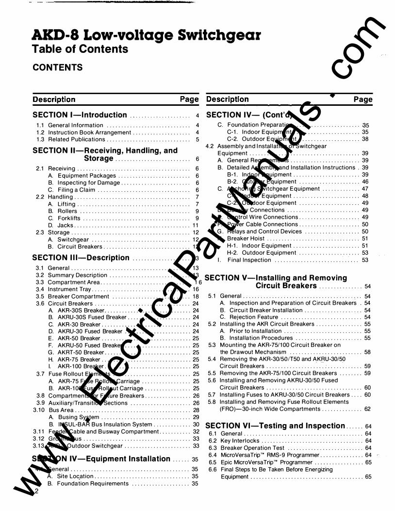
1 . Lifting plate 2. Sh ippi ng sk id 3. Lift ing plate mount ing bolts 4. Yel low tape l abel ing (expendable
material)
Fig. 2-4. Location of lifting p lates AKD-8 outdoor enclos u re
/ SPREADER PI '
qll r ClCJ
Ci] rv 'if
( t� ]
FRONT VIEW
NOT FU RN ISHED TH SWITCHGEAR )>(w1
r l � F RONT
\?
I� c.Uf
REA R
S IDE V I EW
F ig . 2-5. Reco m m ended method of l i ft i ng AKD-8 outdoor enclosure by crane u s i ng cable spreader
www . El
ectric
alPar
tMan
uals
. com
SECTION 11-Receiving, Handling, and Storage
Take up the slack in the l i ft ing device very carefu l ly and manual ly stabi l ize the switchgear to prevent i t from rotat ing.
WARNING: DO NOT STAND UNDER SWITCHGEAR WHILE IT IS BEING MOVED. SERIOUS INJURY MAY OCCUR IF THE CABLES OR LI FTING DEVICE FAI L.
CAUTION : GENTLY LOWER THE SWITCHGEAR SECTION ONTO THE LEVEL S ITE LOCATION. I F T H E SWITCHGEAR I S ROUGHLY HANDLED OR JAR RED, IT IS POSSIBLE TO DAMAGE OR M ISALIGN INTERNAL COM PON ENTS.
Methods of l ifti ng outdoor switchgear sections are much the same as for i ndoor equipment except the l ifting plates are provided at the base of the structu re. See Fig. 2-4.
I f l i fting outdoor switchgear sections, side support t imbers must be placed along the sides to prevent any damage that cou ld be caused by the l i ft ing cables. In addit ion, a spreader bar must be i nserted between each l i ft cable, both front and rear, above the switchgear equ ipment as shown in Fig. 2-5.
Proceed to l i ft and place the outdoor switchgear uti l iz ing al l the precautions and requ i rements that apply to l i ft ing the indoor switchgear.
The l i ft ing p lates, Fig. 2-4, shou ld be removed after the equ ipment is permanently anchored so passageways at the ends of the equi pment wi l l no.t be obstructed.
B. Rol lers I f crane faci l it ies are not avai lable, the eq uipment may be moved i nto position by means of construction rol lers placed under the sh ipp ing skids. The switchgear may be raised enough for the placement of rol lers by means of a fork l i ft or jack.
There should never be less than four rol lers under the equ ipment un less the l i ne-up is less than five feet long. Use one rol ler for each 18 i nches of equ ipment length .
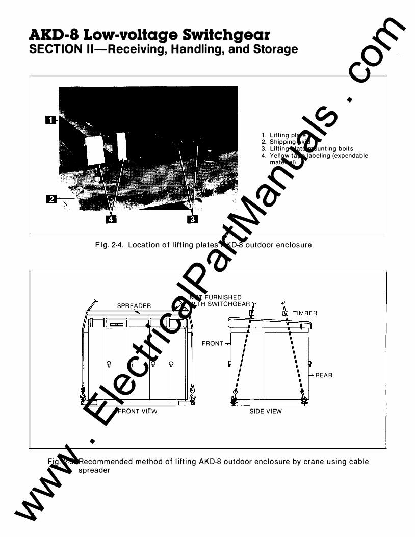
C. Forkl ifts When using a forkl ift to raise the l i ne-up to position rol lers underneath , proceed as fol lows :
1 . Expand forkl i ft tines to thei r maxi mum (widest) extension.
2. Carefu l ly i nsert tines of forkl ift below one side of the switchgear l i ne-up at the approx imate center of the panel as shown in Fig. 2-6.
NOTE: Do not attempt to l ift or move the equ ipment with a forkl ift positioned in the front or rear of the equ i pment.
3. Posit ion one man in the front and one man in the rear of the switchgear to stabi l ize the equ ipment as it is being raised .
4. Position one rol ler under the skids close to the raised end of the l i ne-up .
5. Carefu l ly lower the gear unt i l it rests on the ro l ler as shown in Fig. 2-7.
6. Repeat the l ifti ng process at the other end and p lace the appropriate number of rol lers under the skids spacing them evenly across the width of the l i ne-up.
Fig. 2-6. P lac ing forkl ift tines under AKD-8 eq u i pment sh ipp ing sk id
F ig. 2-7. Placement of rollers under shipping ski d
9 www . El
ectric
alPar
tMan
uals
. com
AKD-8 Low-voltage Switchgear SECTION 11-Receiving, Handling, and Storage
fJ
-
LI FT ING PLATES MUST BE REMOVED WH ERE SECTIONS ARE JO INED �
(0) CO) (0) (0) --
FRONT V IEW S IDE V IEW
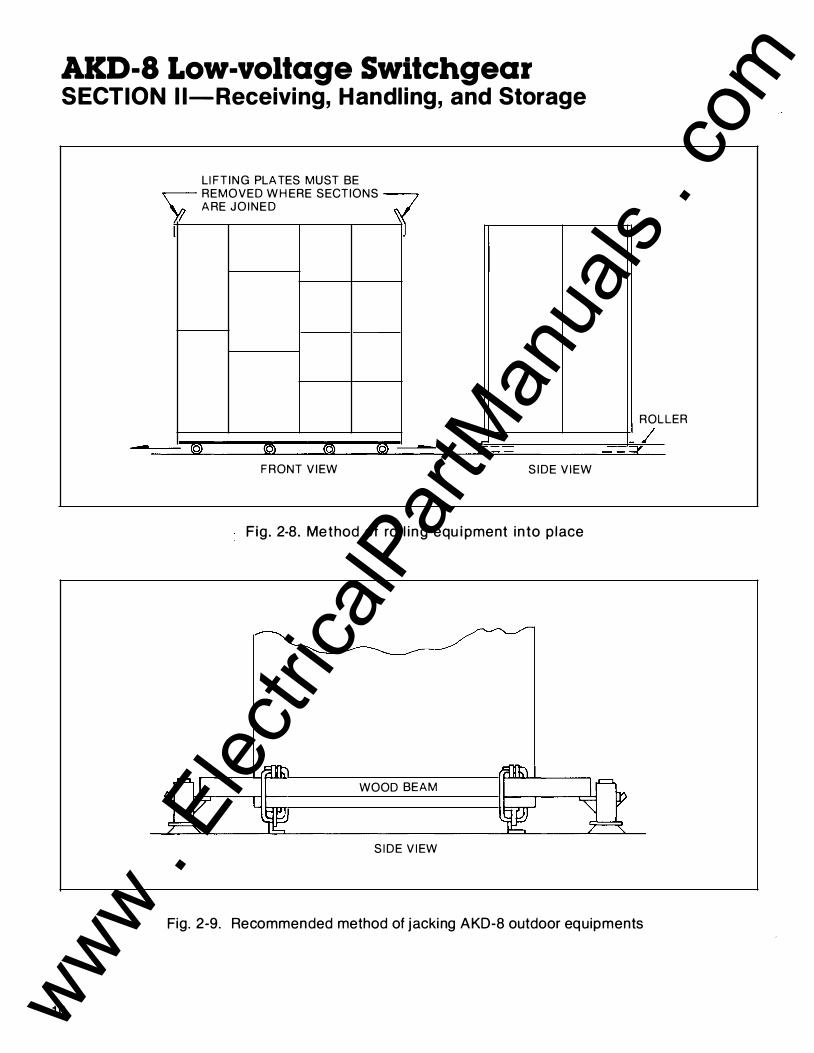
Fig. 2-8. Method of ro l l ing equipment into p lace
WOOD BEAM
S I DE V I EW
ROL
�
Fig. 2-9. Recommended method of jacking AKD-8 outdoor equipments
10
LER
www . El
ectric
alPar
tMan
uals
. com

SECTION 11-Receiving, Handling, and Storage
FRONT V IEW
JAC K I N G T IM BER N OT F U R N I S H ED WITH SWITC H G EAR
PARTIAL FRONT OR REAR V IEW OF JAC K I N G
REAR O R FRONT
JACK H ERE
PARTIAL SIDE V I EW FOR JACK ING
F ig . 2-1 0. Recom mended m ethod of jack ing AKD-8 outdoor enclosure
7. Carefu l ly lower the gear unt i l it rests on the rol lers (Fig. 2-7).
NOTE: I f sh ipping skids are removed prior to f inal p lacement of equ ipment, ro l lers may only be used to move the equipment in a di rection paral le l to the front.
8. Wh i le carefu l ly push ing the switchgear to its final site posit ion, the rol lers that are freed from the rear of the switchgear are then repositioned at the forward end. This procedure should be contin ued unti l the switchgear is in its f inal location . See Fig. 2-8.
9. When the switchgear is in its f inal position , remove a l l l ug bolts ho ld ing the shipping skids to the switchgear l i ne-up .
1 0. Insert the tines of the forkl i ft at one end of the l i ne-up, raise s l ightly, and remove the loose rol lers.
1 1 . Lower the end of the gear carefu l ly to the f loor.
1 2. Raise the other end of the l ine-up s l ight ly and remove the remain ing rol ler at that end .
D. Jacks Jacks may be used in place of forkl ifts to raise and lower switchgear.
1 . Place a jack under the front and rear corners of one end of the l ine-up. F igures 2-9 and 2-1 0 i l l ustrate the use of jacks with outdoor equ ipment.
CAUTIO N : DO NOT PLACE JACKS IN ANY OTH ER LOCATION OTHER THAN THE FRONT AND REAR CORNERS OF THE SWITCHGEAR. DOING SO MAY RESULT IN SERIOUS DAMAGE TO THE SWITCHGEAR EQUIPMENT.
2. Raise the switchgear evenly and j ust enough to position a rol ler beneath the equ ipment. Gently lower the switchgear onto the rol ler. Repeat the procedure at the opposite end of the switchgear, rais ing the gear far enough to p lace the appropriate number of rol lers under the skids, spacing them evenly across the width of the l i ne-up. Gently lower the gear onto the ro l lers.
3. Whi le carefu l ly push i ng the switchgear to its final site position , the rol lers that are freed from the rear of the switchgear are then repositioned at the forward end. This procedure should be cont inued unt i l the switchgear is in its f inal locat ion.
4. When the switchgear is in i ts f inal position , remove a l l lug bolts ho ld ing the sh ipping skids to the switchgear l i ne-up.
5. Place one jack at each corner, front and rear, of the switchgear. Carefu l ly raise the l i ne-up evenly and remove the rol lers and the sh ipp ing skids. Evenly lower the l i ne-up to the floor and remove the jacks.
1 1 www . El
ectric
alPar
tMan
uals
. com
1 2
AKD-8 Low-voltage Switchgear SECTIO N 11-Receiving, Handl ing, and Storage
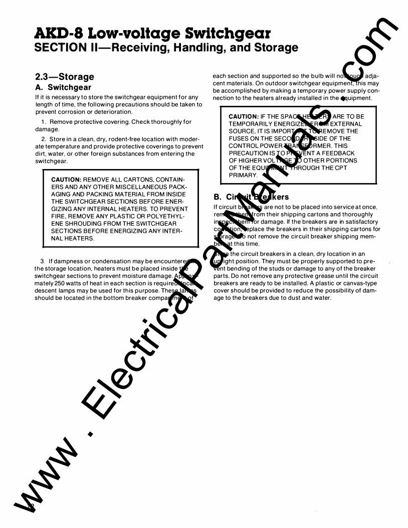
2.3-Storage A. Switchgear I f it is necessary to store the switchgear equipment for any length of t ime, the fol lowing precautions should be taken to prevent corrosion or deteriorat ion.
1 . Remove protective cover ing. Check thorough ly for damage.
2. Store in a clean, d ry, rodent-free location with moderate temperature and provide protective coverings to prevent d i rt , water, or other foreign substances from entering the switchgear.
CAUTION: REMOVE ALL CARTONS, CONTAINERS AND ANY OTHER M ISCELLANEOUS PACKAGING AND PACKING MATERIAL FROM INSIDE THE SWITCHGEAR SECTIONS BEFORE ENERGIZING ANY INTERNAL HEATERS. TO PREVENT FIRE, REMOVE ANY PLASTIC OR POL YETHYLENE SH ROUDING FROM THE SWITCHGEAR SECTIONS BEFORE ENERGIZING ANY INTERNAL HEATERS.
3. I f dampness o r condensation may be encountered in the storage locat ion, heaters must be placed inside the switchgear sections to p revent moisture damage. Approximately 250 watts of heat in each section is requ i red. I ncandescent lamps may be used for th is pu rpose. These lamps should be located i n the bottom breaker compartment of
each section and supported so the bu lb wi l l not touch adjacent materials. On outdoor switchgear equ ipment, this may be accompl ished by making a temporary power supply connection to the heaters al ready i nstal led in the equipment.
CAUTIO N : IF THE SPACE HEATERS ARE TO BE TEMPORARILY ENERGIZED FROM EXTERNAL SOURCE, IT IS IM PORTANT TO REMOVE THE FUSES ON THE SECONDARY SIDE OF THE CONTROL POWER TRANSFORMER. THIS PRECAUTION IS TO PREVENT A FEEDBACK OF HIGHER VOLTAGE TO OTH ER PORTIONS OF THE EQUIPMENT THROUGH THE CPT PRIMARY.
B. Circuit Breakers I f c i rcu it breakers are not to be p laced i nto service at once, remove them from their sh ipp ing cartons and thoroughly inspect them for damage. If the breakers are in satisfactory condit ion, replace the breakers in their sh ipp ing cartons for storage. Do not remove the circuit breaker sh ipp ing members at th is ti me.
Store the c i rcuit breakers in a clean, d ry location in an upright position . They must be properly supported to prevent bending of the studs or damage to any of the breaker parts. Do not remove any p rotective g rease unt i l the c i rcu it breakers are ready to be instal led. A p lastic or canvas-type cover should be provided to reduce the possib i l ity of damage to the breakers due to dust and water.
www . El
ectric
alPar
tMan
uals
. com

SECTION I l l-Description
3.1 -Ge neral This section contains a description of the General Electric AKD-8 Low-voltage Switchgear. It also describes the functions of the e lectrical and mechanical systems.
F igure 3-1 shows the instal lation of a typical s ingle-ended load center un it substat ion.
3.2-S u m m ary Description General E lectric AKD-8 Low-voltage Switchgear is a freestanding assembly of metal-enclosed sections contain ing low-voltage power c i rcu it breakers, bus bars, cable termi nation p rovisions, auxi l iary power circuit p rotective devices, controls, and i nstrumentation. It may also be an integral part of a load center un i t su bstation, either sing le-ended or double-ended.
Fig. 3-1 . Installation of a typical AKD-8 Load Center Unit Substation
1 3 www . El
ectric
alPar
tMan
uals
. com

AKD-8 Low-voltage Switchgear SECTIO N I l l-Description
Figure 3-2 i s a s ide view of a typical section showing compartmentat ion . Fig u re 3-3 is an outl i ne of a typical
s ing le-ended load center u n it substat ion i l l ustrat ing the nomenclature used for al l eq u i pment.
1 4
I NTER-SECTIONAL CONTROL W I R I N G TROUGH
COM PARTM ENT DOOR
VERTICAL CONTROL
WIRE GUTTER
INSTRU M ENT TRAY
I I
BREAKER OR I INSTRUMENT I COMPARTM ENT
I A I
I I I I
B I I [__________.) I BREAKER I COMPARTM ENT
I c I
I BREAKER I COMPARTMENT
I D
N EUTRAL BUS__[] VERTICAL RISER BUS BARS
CABLE TERM I N ATION AREA
BREAKER COM PARTMENT RUN BACK AND CABLE TERM I N ATION
BREAKER COM PARTM ENT RU N BACKS AND CABLE TERM I N ATION
lj I I I I I I L __ -J
Fig. 3-2. S ide-view section of AKD-8 switchgear
CABLE COMPARTM ENT DOORS
ENC LOSED TROUGH-CONTROL C I RCUIT (WH E N REQU I R ED)
GROU N D BUS
www . El
ectric
alPar
tMan
uals
. com

SECTION I l l-Description
Al l of the primary circuit switch ing and p rotective devices, secondary control and metering devices, control fuses, and instru ment transformers are mounted in the enclosure. The breaker compartments inc lude d rawout rai ls, stationary breaker contacts, interlocks, and necessary control and indi-
eating devices. The breakers are provided with self-al ign ing pr imary and secondary d isconnecti ng contacts, breaker locking mechanism, and integral trip programmer. The ind ividual sections, compartments, and devices are described in the fol lowi ng paragraphs.
LOA D CENTER U N I T SUBSTAT I O N f--- P R I M A R Y -
S ECTION �TRANSFORMER�
r---S H I PP I N G ___ PACKAG E
f.-- SWITCH l -UNIT
111
r---------_
r---------_
� l11t I 0
AKD-8 LOW-VOLTAG E SECTION
PACKAG E PACKAGE SHI P PING I SHIPPING
TRANSITION[--BR EAKER S ECTI ONS � S ECTION I ll A
� D � � A A
D � � D � D A B B B
� D � D � D � c c
c
� D � D B D D D
F ig. 3-3. Out l i n e of typ ical AKD-8 Load Center U n it Substat ion
1 5 www . El
ectric
alPar
tMan
uals
. com

AKD-8 Low-voltage Switchgear SECTION I l l-Description
3.3-Compartment Area The front enclosure of each section is d ivided into ind ividual compartments. These compartments house either a lowvoltage power circuit breaker or are used to mount instruments, control components and other anci l lary devices.
WARNING: WITH THE STANDARD SLIDE-OUT INSTRUMENTATION TRAY IN THE OPEN POSITION, LIVE TERMINALS ARE EXPOSED. TOUCHING THESE TERM INALS MAY RESULT IN E LECTRICAL SHOCK OR BURN.
1 . Ammeter
3.4- l nstru ment Tray A standard sl ide-out instrumentation tray, F ig . 3-4, is located above each breaker compartment e l im inat ing cross-hi nge wiring . When requ i red , optional feeder instrumentation may be included and mou nted on the front face of the tray such as a horizontal-edgewise ammeter, am meter switch , p i lot l ights or annu nciator, and test switches.
2. Ammeter switch
1 6
3. Pirot l ights 4. Control c i rcu it fuse 5. Gri l le 6. Vent i lat ion open ings in sta
t ionary cover
F ig. 3-4. S l i de-out i n st rument t ray
www . El
ectric
alPar
tMan
uals
. com

SECTION I l l-Description
Fuses for the close and tr ip c i rcu its o f the electrical ly operated b reakers are mounted inside the tray and are fu l ly accessible when the tray is pu l led out. Routine wir ing i nspections and fuse checks or fuse replacements can be performed with the breaker com partment door in the closed position so that operators are protected from the energ ized pr imary c i rcu its.
The i nstrument tray also permits the flow of venti lat ing air to the breaker compartment. The g ri l le , (5) , F ig . 3-4, on the tray face with the open i ngs (6) in the stationary cover provide an i nd i rect path for the entrance of cool i ng air .
An i nstru ment compartment with a recessed swing ing i nstrument panel, F ig . 3-5, is avai lable as a standard featu re. These panels can be used to mount meters and/or i nstruments and other devices associated with the i ncoming supply c i rcu it. Switches used in various control c i rcu its may also be instal led on these panels.
Relays, fuse cutouts and s im i lar devices may be i nstal led in the compartment beh i nd the swing-out i nstrument panel or i n adjacent compartments.
F ig . 3-5. Recessed sw ing ing i n st rument panel
1 7 www . El
ectric
alPar
tMan
uals
. com

AKD-8 Low-voltage Switchgear SECTION I l l-Description
3.5-Breaker Compartment Closed-door d rawout c i rcu it breaker compartments, Fig. 3-6, are standard construction with a l l AKD-8 switchgear eq u ipment. The circuit breaker compartment doors remain closed and latched whi le the breaker is racked out from the connected posit ion , through test, to the d isconnected posit ion .
Breaker compartment doors do not have any venti lation slots, thus protect ing operators from hot ion ized gases which may be vented by the breaker du r ing circuit i nterrupt ion . Addit ional ly, the breaker compartment, F ig . 3-7, is enclosed by g rounded steel barriers on the top, sides, bottom, and front. In the back a f lame-retardant, arc track resistant g lass-f i l led polyester base m in im izes the possib i l ity of fau lt commun ication between compartments or to the bus.
1. Compartment door 2. Access port to racking mechanism 3. Racki ng crank 4 . Circu i t breaker escutcheon 5. Breaker posi t ion label
Fig. 3-6. AKR-75 c i rc u it breaker compartment
1 8 www . El
ectric
alPar
tMan
uals
. com

SECTION I l l -Description
1 . Side barrier 5. Primary disconnects - load 2. Top and bottom barriers 6. Drawout rai ls 3. Rear base/barrier 7. Anchor pins 4. Primary d i sconnects - l i ne
Fig. 3-7. Circuit b reaker compartment (22-inch) showing rol l out carriage for AKR-30/50/T50 breakers
1 9 www . El
ectric
alPar
tMan
uals
. com
AKD-8 Low-voltage Switchgear SECTIO N I l l-Description
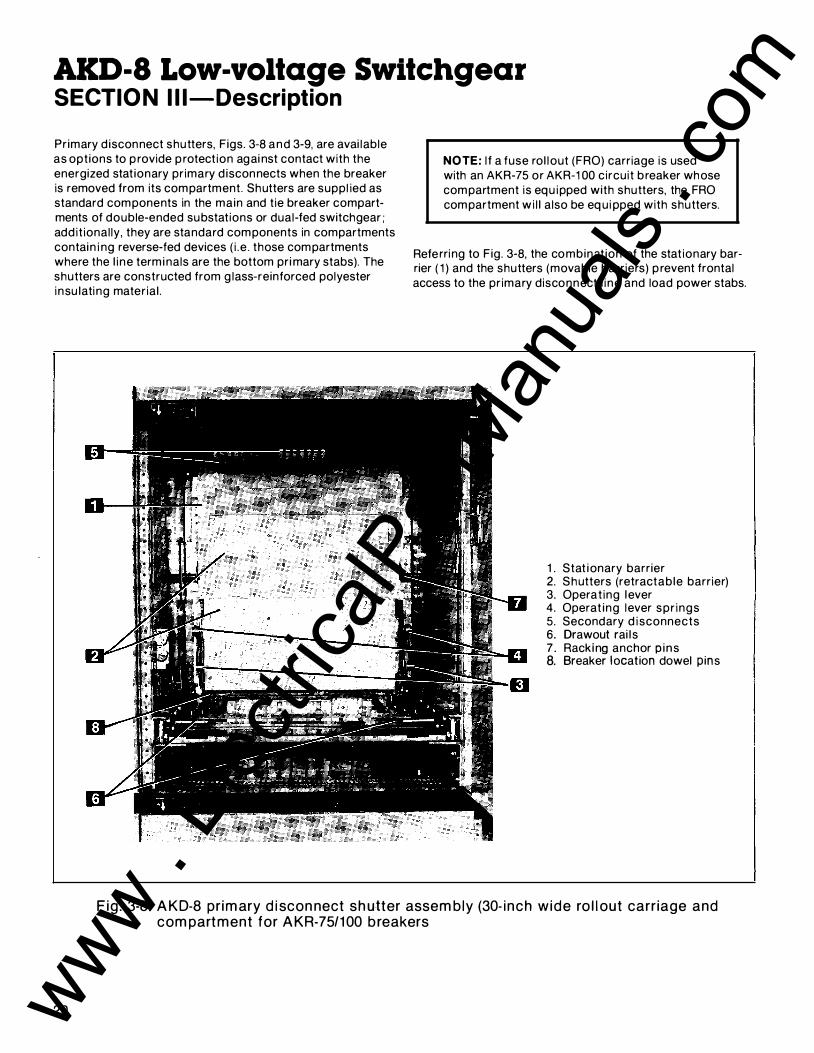
Primary d isconnect shutters, Figs. 3-8 and 3-9, are avai lable as options to p rovide p rotection agai nst contact with the energized stat ionary primary d isconnects when the breaker is removed from its compartment. Shutters are suppl ied as standard components in the main and tie breaker compartments of double-ended substations or dual-fed switchgear; add it ional ly , they are standard components in compartments contain i ng reverse-fed devices ( i .e . those compartments where the l ine terminals are the bottom pri mary stabs). The shutters are constructed from g lass-reinforced polyester insu lating material .
NOTE: I f a fuse rol lout (FRO) carriage is used with an AKR-75 or AKR-1 00 circuit breaker whose compartment is equ ipped with shutters, the FRO compartment wi l l also be eq ui pped with shutters.
Referring to Fig. 3-8, the combinat ion of the stat ionary barrier ( 1 ) and the shutters (movable barriers) p revent frontal access to the primary disconnect l ine and load power stabs.
1 . Stat ionary barrier 2. Shutters (retractable barrier) 3. Operat ing lever 4. Operat ing lever spr ings 5. Secondary d isconnects 6. Drawout rai l s 7 . Racking anchor p ins 8. Breaker location dowel pins
Fig . 3-8 . AKD-8 pr imary d i scon nect shutter assembly (30- inch w ide ro l l out carr iage and compartment for AKR-75/1 00 breakers
20 www . El
ectric
alPar
tMan
uals
. com

SECTION I l l-Description
The sh utters are not retracted as the c i rcuit breaker is racked from the Disconnect Position to the Test Position. This arrangement al lows the breaker control c i rcu its to be completed through the secondary d isconnects (5), Fig. 3-8, for test ing pu rposes whi le the shutters remai n i nterposed between the primary power stabs in the equi pment and the primary d isconnects on the c i rcuit breaker.
As the breaker is racked from the Test Position to the Con nected Posit ion, the rear of the circuit breaker frame depresses the shutter operat ing lever (3) to cause the sh utters to be retracted . The operati ng lever springs (4) cause the operati ng lever (3) to remai n in contact with the c i rcu it breaker frame during th is operat ion.
Figu re 3-9 also shows the shutter assembly with the shutters manual ly retracted to show the location of the primary d isconnect stabs (7) beh ind the shutter assembly. Also shown are the shutter c losing springs (6) which cause the closure of the shutters as the breaker is withdrawn from the connected position . These springs are automatical ly charged as the breaker is racked into the connected posit ion.
C i rcu it breakers mounted i n 22- inch wide compartments (AKR-30, AKR-50, AKRT-50, etc.) are supported on d rawout rai ls (6) , Fig. 3-7. The larger AKR-75 and AKR-1 00 circuit breakers and fuse ro l lout carriages are instal led in 30-inch wide compartments and are supported on d rawout rai ls (6) , F ig . 3-8.
1 . Stat ionary barrier 2. Shutters (not v is ib le in
retracted position) 3. Operating lever 4. Operat ing lever springs 5. Secondary d i sconnects 6. Sh utter c los ing spring
(one on each side of assembly) 7. Pri mary d isconnect stabs
Fig . 3-9. AKD-8 primary d isconnect shutter assembly (30- i nch wide compartment). Shutters manual ly ret racted - not normal operat ion .
www . El
ectric
alPar
tMan
uals
. com

AKD-8 Low-voltage Switchgear SECTIO N I l l-Description
1 . Racking arm 2. Trip lever
Fig . 3-1 0. AKR-30 c i rcu i t breaker
Note that extra items shown in Figs. 3-8, 3-9, and 3-1 0 (such as secondary d iscon nects, current transformers, position switches and ground sensor secondary d isconnects) may appear in any compartment or not be inc luded at al l , depending on the equ ipment spec ified. Primary discon nects are equ ipped with short-ci rcuit braces when breakers are fused or when extra-deep breaker compartments are used.
The racking arm s lots engage fixed racking anchor p ins (7), Fig. 3-8, mounted in the breaker compartment. As the racking arms are rotated by operation of the breaker racking crank, the breaker is pu l led into the compartment, and locked in its final connected posit ion.
A breaker should always be OPEN when it is moved into or out of the CONNECTED posit ion. As a safeguard , trip lever (2), Fig. 3-1 0, w i l l cause the breaker to open before the primary disconnects lose contact if a closed breaker is moved out of the CONN ECTED posit ion.
Al l AKR-6D circu it breakers of the same type and rating , which have identical wiring , may be interchanged.
22
1. Racking arms 2. Pri mary d isconnects 3. Secondary d isconnects 4. Racking screw
F ig . 3-1 1 . AKR-75 c i rc u i t breaker (rear v iew)
Each breaker compartment has four posit ions as described below:
1 . CONNECTED POSITION-The breaker is in operating position , both primary and secondary contacts made, and the door c losed.
2. TEST POSITION-The secondary contacts are made. If specified, the optional pri mary d isconnect shutters are posit ioned in front of the pri mary stabs. Any breaker test which requ ires control power may be made in th is posit ion. The compartment door may be closed i n th is position and must be closed before charg ing the spring on a manual ly operated AKR breaker because an open door w i l l i nterfere with the breaker handle travel .
3 . DISCONNECTED POSITION-Al l primary power and secondary control electrical circu its between the breaker and the eq uipment are d isconnected . The door may be closed . The breaker may be stored in th is position with the door c losed .
4. WITHDRAWN POSITION-The breaker is completely out of its compartment ready for removal from the equ ipment. The door must be open.
www . El
ectric
alPar
tMan
uals
. com

SECTION I l l-Description
1 . Breaker escutcheon 2. Breaker pos it ion ind icat ion (both s ides of escutcheon)
F ig . 3-1 2. Rac k i ng c rank for movement of AKR-75 and AKR-1 00 breakers
Movement of the breaker between the con nected, test, and disconnected posit ions is performed by the use of a racking crank which engages the racking mechanism mou nted on the b reaker. See Fig. 3-1 2. Movement to the withdrawn position is manual ly performed after open ing the compartment door.
These positions are i l l ustrated and described more fu l ly in Section V of this i nstruction book.
CAUTION: THE DOOR SHOU LD NOT BE OPENED WHEN THE C IRCUIT BREAKER IS CLOSED AND IN THE CONNECTED POSITION. ALTHOUGH THE B REAKER COMPARTMENT DOOR MAY BE OPENED IN ANY POSITION, IT IS RECOMM ENDED THAT THE DOOR ONLY BE OPENED WHEN THE BREAKER IS IN THE DISCONNECTED OR WITHDRAWN POSITION.
23 www . El
ectric
alPar
tMan
uals
. com

AKD-8 Low-voltage Switchgear SECTION I l l-Description
3.6-Circuit Breakers The General Electric AKR Low-voltage Power Circuit Breaker includes spring-operated, stored energy, close and trip mechanisms for either manual or electrical operation.
Six General Electric AKR Circuit Breakers form the complete family of breakers used in the AKD-B switchgear. These circuit breakers range from BOO to 4000 ampere frame size and are built with the following ratings and characteristics:
A. AKR-305 Circuit Breaker (Fig. 3-13)
• BOO-ampere frame size
• Standard 22,000-ampere interrupting and short-time capability (4BO volts)
• Four-high stacking, 22-inch wide sections
B. AKRU-305 Fused Circuit Breaker • BOO-ampere frame size
• 300 through 1600-ampere integral fusing
• 200,000-ampere interrupting rating
• Four-high stacking, 22-inch wide sections
C. AKR-30 Circuit Breaker (Fig. 3-14)
• BOO-ampere frame size
• Standard 30,000-ampere interrupting and short-time capability (4BO Volts)
• Four-high stacking, 22-inch wide sections
• Increased IC and short-time rating 42,000 amperes at 4BO volts (AKR-30H)
Fig. 3-1 3. AKR-308 circuit breaker
24
F ig . 3-1 4. AKR-30 c i rcuit breaker (e lect r ica l ly operated)
1 . Fuses mounted on pr imary l ine stabs 2. Open fuse lockout device
Fig. 3-1 5. AKRU-30 integrally fused circuit breaker
www . El
ectric
alPar
tMan
uals
. com
SECTION I l l-Description
D. AKRU-30 Fused Circuit Breaker (Fig. 3-15)
• BOO-ampere frame size
• 300- through 1600-ampere integral fusing
• 200,000-ampere interrupting rating
• Four-high stacking, 22-inch wide sections
E. AKR-50 Circuit Breaker • 1600-ampere frame size
• Standard 50,000-ampere interrupting and short-time capability at 480 volts
• Four-high stacking, 22-inch wide sections
• Optional 65,000-ampere extended interrupting and short time capability at 480 volts
F. AKRU-50 Fused Circuit Breaker • 1600-ampere frame size
• 450 thru 2500-ampere integral fusing
• 200,000-ampere interrupting rating
• Four-high stacking, 22-inch wide sections
G. AKRT-50H Circuit Breaker • 2000-ampere frame size
• Standard 65,000-ampere interrupting and short-time capability at 480 volts
• Four-high stacking, 22-inch wide sections (physical loading)
H. AKR-75 Circuit Breaker (Fig. 3-16) • 3200-ampere frame size
• Standard 65,000-ampere interrupting and short-time capability at 480 volts
• Two-high stacking, 30-inch wide sections
Fig. 3- 1 6. AKR-75 c ircu it breaker (manually operated)
• Increased IC and short-time rating 85,000 amperes at 480 volts (AKR-75H)
I. AKR-1 00 Circuit Breaker • 4000-ampere frame size
• Standard 85,000-ampere interrupting and short-time capability at 480 volts
• Two-high stacking, 30-inch wide sections (main-tie)
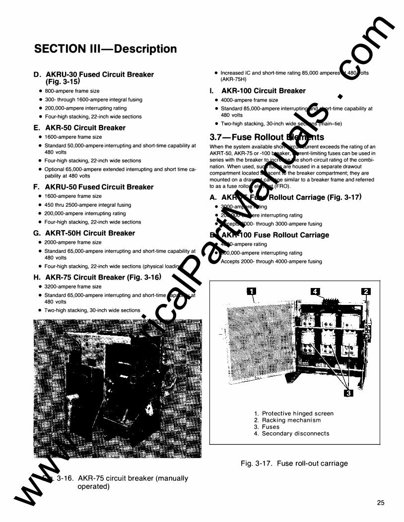
3. 7- Fuse Rollout Elements When the system available short-circuit current exceeds the rating of an AKRT-50, AKR-75 or -100 breaker, current-limiting fuses can be used in series with the breaker to increase the short-circuit rating of the combination. When used, such fuses are housed in a separate drawout compartment located adjacent to the breaker compartment; they are mounted on a drawout carriage similar to a breaker frame and referred to as a fuse rollout element (FRO).
A. AKR-75 Fuse Rollout Carriage (Fig. 3-17) • 3000-ampere rating
• 200,000-ampere interrupting rating
• Accepts 2000- through 3000-ampere fusing
B. AKR-1 00 Fuse Rollout Carriage • 4000-ampere rating
• 200,000-ampere interrupting rating
• Accepts 2000- through 4000-ampere fusing
�\
1 . Protective hinged screen 2. Racking mechanism 3. Fuses 4. Secondary disconnects
Fig. 3-1 7 . Fuse rol l-out carriage
25 www . El
ectric
alPar
tMan
uals
. com

AKD-8 Low-voltage Switchgear SECTION I l l-Description
3-8-Compa rtments for Future Breakers
When specified, compartments may be suppl ied for future addit ion of circuit breaker elements. These compartments are fu l ly equ ipped with racking tracks or trays, pr imary d isconnects, and anci l lary devices as requi red ( i .e . secondary disconnects, accessory devices, etc.) The open ing in the breaker compartment door (2) , F ig. 3-1 8, is closed with a snap- in molded cover (3) and a metal barrier ( 1 ) is bolted across the face of the compartment to deter accidental contact with energized electrical c ircu its (i.e. pr imary d isconnect stabs).
1 . Metal compartment barrier 2. Compartment door 3. Snap- in cover 4. Draw-out ra i ls 5. Accessory (pad locking device)
Fig . 3-1 8. Future breaker compartment
26
3.9-Auxi l iary/Transition Sections Sections may be provided for any one or more of several reasons i nc lud ing:
• Transit ion to a close-coupled transformer
• Transition to "match and l i ne-up" with exist ing nonAKD-8 switchgear
• I ncoming l i nes where the c i rcu it is bottom entry and reverse feed is not acceptable (auxi l iary)
• Incoming busway where additional termination space is required (auxiliary)
• Mounting and wiring of additional metering, relaying, and control devices requiring more space than available in a standard instrument tray or instrumentation compartment (transition or auxi liary)
• Mounting and wiring of purchaser specified and/or furnished devices ( i .e . utility revenue metering equipment, etc.) (auxiliary)
Auxi l iary sections may be 22- inch, 30-i nch, or 38-i nch wide as requ i red to accommodate the space requ i rements. The compartment doors on the front of the sections are hi nged and latched in the same manner as breaker compartment doors.
Generally, transition sections wi l l be 22- inches wide for close-coupl ing to transformers and "match and l i ne-up" to non-AKD-8 equ ipments. Transition section width to an AKD-5 or -6 eq uipment is usual ly twelve i nches.
Power company meter ing requ i rements general ly requ i re either a 30- inch or 38-inch wide auxi l iary section to accommodate the cu rrent transformers, k i lowatt-hour meters, demand meters, etc. as requ i red by the i r i ndividual practices, tariff schedu les, and/or regu latory commissions.
F igure 3-1 9 is a partial front view of a typical auxi l iary/ transit ion section .
Electric i nd icat ing i nstruments are located i n the top compartment ( 1 ) , Fig. 3-1 9, (part ial ly shown) , an auxi l iary relay (2), and fuse cutouts (3) i n the middle compartment, and potential transformers (4) and a control power transformer (5) in the lower compartment.
www . El
ectric
alPar
tMan
uals
. com

SECTION I l l-Description
1 . Instrument compartment 2. Auxiliary relay 3. Fuse cutouts 4. Control power transformer 5. Potential transformer
Fig . 3-1 9. Aux i l iary/t rans i t ion sect ion - part ia l front view
1 . Enclosed fuse cutouts 2. Open fuse cutouts
Fig . 3-20. Aux i l iary/t rans i t ion compartments -view of bottom sect ion
27 www . El
ectric
alPar
tMan
uals
. com

AKD-8 Low-voltage Switchgear SECTION I l l-Description
Figure 3-21 i l l ustrates an auxiliary/transition compartment with switchgear-type relays mounted in semi-f lush d raw-out cases (2) instal led on the compartment door ( 1 ) . Space in the compartment has been used for storage of spare power fuses (3) . .
1. Compartment door 2. Relays in draw-out cases 3. Spare power fuse storage
(Optional) 4. Auxiliary relay 5. Fuse cutouts
F ig. 3-21. Auxil iary/transition compartments -view of top sect ion
28
3.1 0-Bus Area The bus area, Fig. 3-22, contains the main horizontal bus and vertical riser bus bars ( 1 ) for the particular section . The vertical bus bars are supported at the breaker run-ins (2) which are bolted to the molded bases (3) that form the rear wall of the breaker compartment. The horizontal bus bars are supported by the power connectors (4) which are bolted (copper) or welded (aluminum) to the vertical bus bars. All bolted supports and connections are accessible from the rear for maintenance. The bus area is fully isolated from the breaker, instrument and auxiliary compartments by the molded bases or glass polyester sheet.
1 . Vertical riser bus 2. Run-ins to breaker compartment 3. Molded base 4. Power Connector 5. Run-backs from breaker compartment 6. Short-circuit brace
Fig. 3-22. Bus construction
www . El
ectric
alPar
tMan
uals
. com

SECTION I l l-Description
A. Busing System The standard construction is open bus. A barrier system (Bus compartmentation) that isolates the main and vertical bus bars from the cable area is available as an option. All run-backs (load-side power conductors) from the breaker compartment to the cable termination area are covered with non-PVC insulated tubing.
Aluminum vertical buses are welded to breaker run-ins which are bolted to molded, glass reinforced polyester bases. This provides a rigid support structure. Aluminum power connectors are welded to the vertical bus bars.
The typical arrangement with an al l-welded alumin,um bus is shown in Fig. 3-23. Bolts at bus joints are used only for mechanical support or at connections which must be made in the field. The bolts present on welded aluminum joints are only for supporting and positioning bus bars prior to welding. Once the joints are welded, these bolts perform no further function. However, it is recommended that the bolts be left in place.
The bus system is also available with copper conductors as an option. This system utilizes bolted connections between all joints, and to the breaker compartment run-ins.
The standard bracing for either the welded aluminum or the bolted copper is 65,000 amperes, RMS symmetrical . Bracing for 1 00 ,000, 1 50,000 and 200,000 amperes, RMS symmetrical is available as an option.
A luminum bus bars between sections are bolted and then welded together to p rovide one cont inuous a luminum main bus. In general , when the switchgear equipment has no more than fou r sections or does not exceed 1 0 feet in length, it wi l l be shi pped as one complete l ineup. I n such cases, the only f ie ld assembly would be to a close-coupled transformer if the switchgear were part of a Load Center Un it Substation. If , because of shipping and/or hand l ing considerations, the equ ipment cannot be hand led in one p iece, it can be spl i t into two or more l ine-ups at the factory. The ind ividual sh ipping spl its requ i re both mechan ical and electrical connections between sections to be made in the field. At these sh ipp ing spl its, provisions are made for bolti ng al l buses and making the necessary electrical and mechanical con nections. These are described in Section IV of this pub l ication.
On main and tie breakers, the bus area, Fig. 3-23, is divided into an upper (1 ) and lower (2) section by a glass reinforced polyester isolation barrier (3) . For the main circuit breakers, the upper section contains the incoming l ine bus (1 ). This bus is fed from the bus connections (4) in the transition section. The lower section of the bus area contains the load side main bus (5) (protected by the main breaker) which feeds al l sections of the switchgear equipment. Simi larly, barriers at tie breakers isolate the two main bus sections from each other.
1 . Upper section vertical bus-incoming l ine 2. Lower section vertical bus-load side 3. Barrier between upper and lower vertical
bus sections 4. Incoming main bus 5. Main horizontal bus to other sections 6. Optional molded, glass reinforced polyester
phase isolation barriers
Fig . 3-23. Ma in breaker bus arrangement
29 www . El
ectric
alPar
tMan
uals
. com

30
AKD-8 Low-voltage Switchgear SECTIO N I l l-Description
B. I NSUL- BAR Bus System™ A bus insulat ion system, Fig. 3-24, that fu l ly insu lates and isolates each phase of the main and vert ica l buses is optional ly avai lable for AKD-8 switchgear when specified. With the INSUL-BAR system, there are no l ive connections accessible in the rear of each sect ion except the cable lugs.
A vertical barrier (2) , F ig. 3-25, between the transit ion sect ion (1 ) and the f i rst breaker section is furnished where specified.
1 . Horizontal ma in bus 2. Vert ica l riser bus covers 3. Run-backs to feeder cables 4. Neutral bus
Fig . 3-24. l nsui-Bar insulation/isolation system
The buswork in the device/aux i l iary/t ransit ion sections is not insu lated at the termination poi nts to the other connected equ ipments such as transformers, busway, or existing equ ipments.
1 . Trans i t ion compartment 2. Barrier 3. Ma in i ncom ing bus 4. Neutral bus 5. Ground bus
Fig. 3-25. Transition section
www . El
ectric
alPar
tMan
uals
. com

SECTION I l l-Description
Insulation and isolation of the vertical riser bus bars (2) , Fig. 3-26, is provided by installing phase isolation barriers (3) between the bus bars and by mounting covers (4) over the bus bars. (The top portion of the vertical bus is shown with the cover removed .)
1 . Molded base
lt�W \�.
2. Vertical riser buses (cover removed to show bus location)
3. Phase isolation barriers (See Figure 3-23, Item 6) 4. Covers over riser bus 5. Insulated horizontal main buses 6. Covers for vertical/horizontal bus joints 7. Insulated run backs
Fig . 3-26. l n sui -Bar i n sulat ion/ isolat ion bus system
The phase isolation barriers and riser bus covers are constructed from glass-reinforced polyester insulating material. Insulation of the horizontal main bus bars (5) is achieved by a powder coating of insulating material.
Figure 3-27 i l lustrates the various components comprising the insulation/isolation system for the horizontal main bus bars. The horizontal bus bars (2) are insulated with an epoxy coating applied by a fluidized bed process. The vertical/horizontal bus bar joints are covered with insulating collars (3) and caps (4) held in place with nylon thumb screws (5) . The collars and caps are constructed from glass-reinforced polyester insulating material .
NOTE: Aluminum bus bars would normally be welded at the power connectors to the vertical riser bus bars.
1 . Vertical bus barrier 2. Insulated bus bar (powder coated) 3. Joint collars 4. Joint caps 5. Nylon thumb screws
Fig . 3-27. l n sul -bar hor izontal bus i n sulat ion system
31 www . El
ectric
alPar
tMan
uals
. com

AKD-8 Low-voltage Switchgear SECTION I l l-Description
3.1 1 -Feeder Cable and Busway Compartment
The rear cable and termi nal compartment, F ig . 3-28, provides for cable i nstal lation and terminat ions. The cable bending space meets the requ i rements of the 1 981 National Electric Code. Various arrangements of s ingle or double cable terminals are provided, depending upon the purchaser's requ i rements.
When specif ied, racks ( 1 ), Fig. 3-28, for the support of feeder cables are located in the cable compartment. The actual support of the cables is provided by lash i ng them to these racks.
Also located in the cable compartments are provisions for termi nati ng control wire cables between external devices and control c ircu its with i n the switchgear equ ipments. See
1 . Support rack for customer's feeder cables 2. Cable lugs - mechani cal type 3. Cable lugs - compression type
Fig. 3-28. Cable termination provisions
32
Fig. 3-29. When furn ished, the termi nal boards (2) , F ig . 3-29, for such connections are mounted in an enclosed vertical wir ing trough mounted on the side of the cable compartment. The trough is of steel construction with bolted covers to provide an isolat ion barrier between the control wir ing (1 ) and the adjacent power cables.
A neutral bus, insu lated from ground , is provided in the bus area on switchgear designed for four-wire systems. As shown in Fig. 3-30, the neutral bus (1 ) is located near the top of the cable compartment. It inc ludes provisions for terminat ing the neutral conductor of four-wi re feeder cables and also d i rect mounting of the neutral CT as requi red for those feeder system circu it breakers havi ng an i ntegral g roundfault trip funct ion.
1 . I nternal equ ipment contro l wir ing 2. Terminal boards 3. Space for purchaser's f ie ld control wir ing
Fig . 3-29. Control wir ing termination trough
www . El
ectric
alPar
tMan
uals
. com

SECTION I l l- Description
3.1 2-Ground Bus All General Electric AKD-8 switchgear sections are g rou nded to the internal equ ipment g round bus (4), Fig. 3-30, located at the bottom of the cable compartment.
1 . Neutral bus (upper position) 2. Fourth wire ground sensors 3. Feeder runbacks 4. Ground bus 5. Neutral bus ( lower position)
Fig. 3-30 . Cable termination compartment
3.1 3-AKD-8 O utdoor Switchgear AKD-8 switchgear designed for outdoor installations i s ful ly weatherproofed. See Fig . 3-31 and 3-32. A weatherproof housing completely encloses the switchgear and is p rovided with a walk-in front aisle for easy access to all controls and instruments.
A l ight with wall switch (2), Fig. 3-32 and a 1 1 5-volt conven ience outlet (4) are standard devices suppl ied with outdoor switchgear equ ipments. Also i ncl uded in the walk-in front aisle area are the breaker l ifting device (2) , Fig. 3-31 , and storage provision for the hoist operat ing c rank (3).
1 . Walk-in a is le - 46 inches deep (approx.) 2. Breaker l i ft i ng hoist 3. Hoist operat ing crank 4. I l l um inating l amp
Fig . 3-3 1 . AKD-8 Switchgear outdoor enclosure
33 www . El
ectric
alPar
tMan
uals
. com
AKD-8 Low-voltage Switchgear SECTIO N I l l-Description
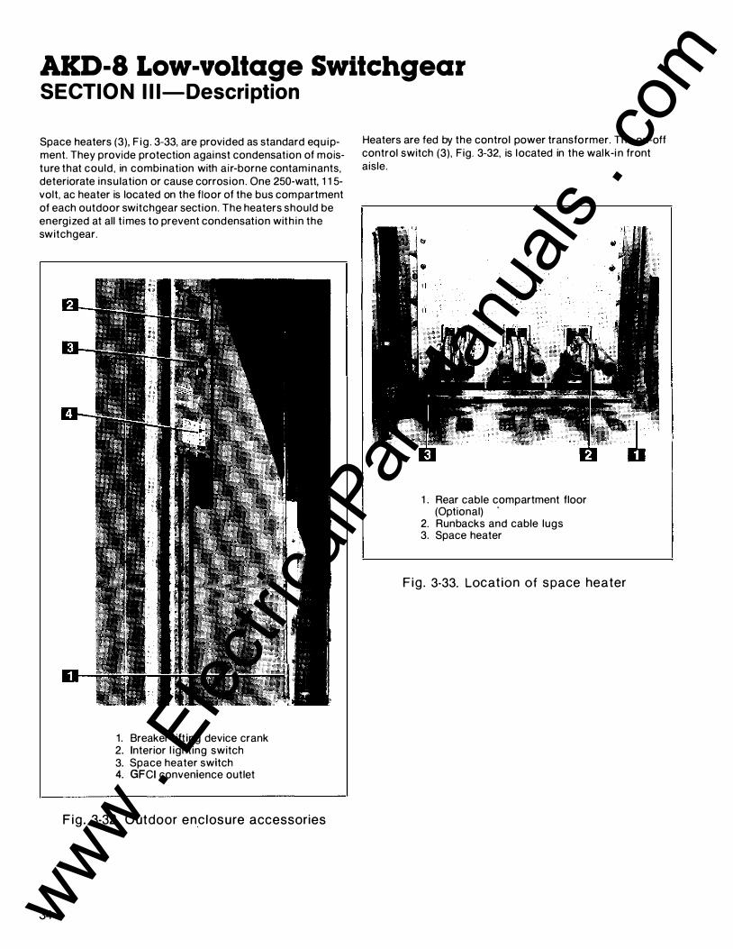
Space heaters (3), F ig . 3-33, are provided as standard equ ipment. They provide protection against condensation of moisture that could, in combination with a ir-borne contaminants, deteriorate insu lation or cause corrosion. One 250-watt, 1 1 5-volt, ac heater is located on the floor of the bus compartment of each outdoor switchgear section. The heaters should be energized at all t imes to prevent condensation with in the switchgear.
1. Breaker l ift ing device crank 2. Interior l ighting switch 3. Space heater switch 4. GFCI convenience outlet
Fig . 3-32. Outdoor enc losure accessories
34
Heaters are fed by the control power transformer. The on-off control switch (3), Fig. 3-32, is located in the walk-i n front aisle.
1 . Rear cable compartment floor (Optional) ·
2. Runbacks and cable lugs 3. Space heater
F ig . 3-33. Locat ion of space heater
www . El
ectric
alPar
tMan
uals
. com

SECTION IV-Equipment I nstal lation
4.1 -General This section contains complete instructions for i nsta l l ing General E lectric AKD-8 Low-voltage Switchgear.
CAUTION: EQUI PMENT INSTALLATION PERSONNEL M UST BE THOROUGHLY FAMI LIAR WITH THIS INSTRUCTION MANUAL AND ALL ARTICLES OF TH E NATIONAL ELECTRICAL CODE APPLICABLE TO THE INSTALLATION OF THIS SWITCHGEAR. IN ADDITION, ALL DRAWINGS, BOTH MECHANICAL INSTALLATION AND ELECTRICAL, M UST BE UNDERSTOOD AND STRICTLY FOLLOWED TO PREVENT DAMAG E TO THE SWITCHGEAR OR EQUIPM ENT BEING PROTECTED BY THE SWITCHGEAR.
NOTE: Before i nstal lation work is started, it is i mportant to review all of the d rawi ngs provided, inc lud ing the General Electric equipment arrangement d rawi ngs, site i nstal lation drawings, elementary and remote connection d rawi ngs, mechan ical con nection d rawings, and the summary of equi pment l ist.
All expendable h ardware for sh ipp ing purposes only, is pai nted yel low or tagged with yel low adhesive tape (as shown in Fig. 2-4) and may be discarded at completion of i nsta l lation phase.
A. Site Location I n genera l , the location of the switchgear equipment wi l l have been predetermined dur ing the specification and/or p rocurement of equ ipment phases. Indoor locations with i n bu i ld ings impose certain req u i rements which must be met so that the switchgear may operate efficiently with a m in imum of maintenance .
In locat ing the AKD-8 Switchgear, adeq uate aisle space must be p rovided at the front and rear of the equ ipment to ensure p roper venti lat ion of the equipment and to al low service and maintenance of the equipment with the front and rear doors open. The recommended aisle space is shown on the floor plan suppl ied with the equipment drawi ngs.
The switchgear equipment should be p laced in an area where clean , d ry a i r is free to c i rcu late around and above it . Si nce a i r is taken into the equ ipment at the bottom of each section and exhausted at the top, a location with good air flow must be p rovided for efficient operation . A min i mum of 30 inches of clear space above the equ ipment is recommended.
B. Fou ndation Req u irements For optimum performance of you r General Electric switchgear equipment, the fou ndation requ i rements expressed i n th is section should b e strictly adhered to.
NOTE: The foundation for the outdoor switchgear must provide p roper d rai nage of g round and/or surface water accumulations away from the equ ipment.
The foundation must be smooth and level in all planes.
C. Fou ndation Preparation C-1 . Indoor Equipment
Refer to F ig . 4-1 a long w ith the owner's fou ndation construction d rawings, and the General Electric supplemental installation d rawi ngs. Although the indoor switchgear equ ipment can be mounted d i rectly on a smooth , level f loor, i t is recommended that recessed steel channels be instal led for support ing the equi pment. Channel si l ls, when suppl ied by the General E lectric Company, are 5 i nches x 1 % i nches nominal , with tapped holes for %-1 3 anchor bolts. The bolts are not suppl ied by General E lectric.
NOTE: When the equ ipment is instal led on a su rface subject to impact (shock) loads due to operating condit ions or envi ronmental seismic (earthquake) conditions , the anch or bolts should be fabricated of med ium carbon steel (grade 5 load rat ing) .
The tapped ho les on channel s i l ls suppl ied by General Electric, are offset one i nch from the center l ine to al low the s i l ls to extend % inch in front of, and to the rear of, the switchgear equipments. The floor chan nels under the front and rear switchgear anchor poi nts (see Fig. 4-1 ) should be embedded in a level concrete slab with their top su rfaces f lush with the f in ished floor. It is essential that these steel channels be level and al igned with each other prior to final anchori ng, to p revent distortion of the switchgear structure, to assure p roper mechanical and electrical connections between sh ipp ing spl its, and to assure proper i nterfacing other close-coupled equipments.
AKD-8 Switchgear and Load Center Substations are frequently mou nted on steel f loors and/or structu ral steel in industrial instal lations (such as a mezzan ine) to m in i mize usage of p roduction floor space. Regardless of the type of mount ing su rface, the requ i rements for a smooth level surface remain.
35 www . El
ectric
alPar
tMan
uals
. com
AKD-8 Low-voltage Switchgear SECTIO N IV-Equipment I nstal lation
F RONT
ANCHOR BOLTS* % INCH
ANCHOR BOLTS* 1 /2-I N C H
GUSSET PLATE (CORNER OF EACH S ECTION)
G USSET PLATE (CORNER OF EACH SECTION)
EM BEDDED C H A N N ELS ( I F USED)
GUSSET SUPPORT;-----����
-=q 3 PLAN V IEW
(D IMENSIONS I N I N C H ES)
*FURN ISHED BY CUSTOMER
REAR
ANCHOR BOLTS* '12 I NCH
REAR S I LL A N G LE
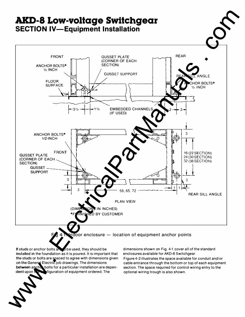
Fig 4-1 . I n door enc losure - locat ion of equi pment anchor po ints
If studs or anchor bolts are t o b e used, they should be installed in the foundation as it is poured. It is i mportant that the studs or bolts are spaced to agree with d i mensions given on the General Electric job drawi ngs. The d i mensions between anchor bolts for a particular i nstal lation are dependent upon the configurat ion of equip ment ordered. The
36
d imensions shown on Fig. 4-1 cover a l l of the standard enclosures avai lable for AKD-8 Switchgear.
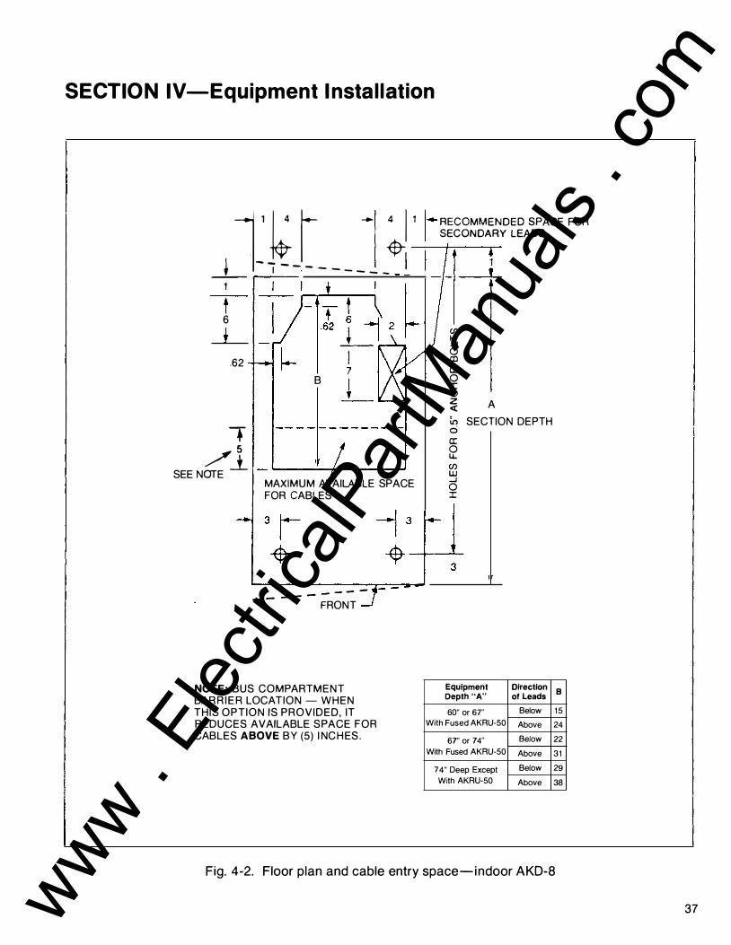
F igure 4-2 i l l ustrates the space avai lable for conduit and/or cable entrance through the bottom or top of each equ i pment sect ion. The space requ i red for control wir ing entry to the optional wir ing trough is also shown .
www . El
ectric
alPar
tMan
uals
. com
SECTION IV-Equipment Instal lation
_L 1� � t- - - --- -�! 1 �-��gg��:����
A�ACE FOR
t 6
t .62
+ /l
SEE NOTE
� 2 � 7
B +
MAXIMUM AVAILABLE SPACE FOR CABLES
- - - - - - - - -FRONT
NOTE: BUS COMPARTMENT BAR R I E R LOCATION - WHEN THIS OPTION IS PROVIDED, IT REDUCES AVAILABLE SPACE FOR CABLES ABOVE BY (5) I NCHES.
(j) 1-_J 0 co a: 0 I (.) z � A
in SECTION DEPTH 0 a: 0 u.. (j) w _J 0 I
Equipment Depth "A" 60" or 67"
With Fused AKRU-50
67" or 74"
With Fused AKRU-50
74" Deep Except
With AKRU-50
Direction of Leads
Below
Above
Below
Above
Below
Above
B
1 5
24
22
31 29
38
Fig. 4-2. Floor plan and cable entry space-indoor AKD-8
37 www . El
ectric
alPar
tMan
uals
. com

AKD-8 Low-voltage Switchgear SECTIO N IV-Equipment I nstal lation
C-2. Outdoor Equipment suppl ied with three bu i lt- in structural suppo rt channels in the base of the switchgear as shown in F ig . 4-3. The front and rear structural support channels are designed to be clamped to the foundation. The center channel is a structural stabi l i-
Refer to Fig. 4-3 along with the owner's foundation construction drawings and the General Electric supplemental installation drawings. The outdoor switchgear equ ipment is
�---------------------8----------------------�
AISLE AREA -.... .-INDOOR AKD-8 SWITCHGEAR___. (44.62)
1 .50 ---.. 1 .50
PROTECTED I A
REAR DOOR
38
FRONT DOOR �
FRONT SUPPORT CHANNEL _____ __.....
�-�::FE:�.---.
1 LINEUP WIDTH
1
t -+
0.88 � � (DIMENSIONS IN INCHES)
NOTE: Four (4) clamp plates are required for each outdoor l ineup. One at each corner.
I
\
l c
l D
CENTER SUPPORT CHANNEL
REAR I SUPPORT CHANNEL l
( I I I
I I l l i
_1_ SIDE VIEW
00 1 1 .
T
+ 1 1 .00
J �t.88 PLAN VIEW AT LEVEL "A"
A B c D Depth of Depth of Anchor Sub
Indoor Outdoor Bolt Base Switchgear Switchgear Spacing Depth
60 1 07.62 1 02.88 1 04.62
74 1 2 1 . 62 1 1 6.88 1 1 8.62
Fig . 4-3. Outdoor enc losure mount i n g det a i l s and anchor bolt locat ion
www . El
ectric
alPar
tMan
uals
. com

SECTION IV-Equipment I nstal lation
zation channel . Although the equ ipment can b e mounted d i rectly on a smooth , level surface, it is recommended that recessed steel channels be i nstalled to support the switchgear. The floor channel si l ls under the front, center, and rear of the switchgear base should be embedded in a level concrete slab with their top surfaces fl ush with the fin ished floor.
Whi le the equ ipment base center channel is not anchored to the fou ndation , it is sti l l requ i red that the center channel s i l l (see Fig . 4-3) be level with the foundation and also with the front and rear channel sil ls to prevent structural d istortion of the switchgear equ ipment.
Only fou r anchor bolts are normally used for outdoor enclosures.
NOTE: The factory must be consulted for anchoring recommendations for equipments subject to operational and/or environmental (seismic) shock load i ng .
Anchor bolts a n d channel are to b e p rovided b y the purchaser; the clamp plates (Fig. 4-4) are suppl ied with the equ i pment.
It is recommended that the anchor bolts be %-inch d iameter.
�4:_1 : ·----,,r-: -� - - - .J_ 2 1 /2 � � r EJ 1�
7/8 DIA: (D IMENSIONS IN INCHES)
F ig . 4-4. Outdoor enc losure c lamp p late
4.2-Assembly and I nstal lation of Switchgear Equipment
A. G e n e ral Requirements Before assembl ing or instal l ing the switchgear equ ipment, all components should be available at the site location. This wil l fac i l i tate switchgear component identification as wel l as i nstal lat ion. The fou ndation should be p repared in accordance with the i nstructions in Sections 4 . 1 and 4.2, and all embedded condu its instal led and capped.
NOTE: I f rol lers are to be used for movement of the equ i pment to its permanent i nstal lat ion, it is recommended that the sh ipp ing skid not be removed unt i l the equ ipment is placed in position over the anchor bolts.
If a t ransformer is not part of the installat ion, and/or the equ ipment has been spl it for sh ipment, p lace the center section on the foundation f i rst. Assemble the remain i ng sections outward from the center section, in each d i rection.
If the switchgear equ ipment is part of a Load Center Unit Substation , the transformer section should be set on its pad f i rst in accordance with the instructions furn ished with the transformer. Al l remain ing sections of the switchgear should then be i nstal led.
NOTE: Prior to assembl ing and instal l ing the switchgear equi pment, the foundation must be absol utely level and clear of debris to prevent damage to the switchgear equ ipment.
B. Detai led Assembly and I nstal lation I n structions
B-1 . I ndoor Equipment
The recommended procedu re for i nstal lation of an i ndoor switchgear or Load Center Unit Substation is as fo l lows :
1 . POSITION THE EQUIPMENT -Position the equ ipment or sections of the complete equipment in their final location.
NOTE: If the equ ipment l i ne-up was spl it i nto sh ipp ing sections, the l ifting plates on corners of adjacent sections shown in Fig. 4-5 must be removed . Fai l u re to remove these plates wil l interfere with mating adjacent sections and prevent instal lation of bus spl ice plates, structure t ie plates, etc .
_LIFTING PLATE
Fig . 4-5. L i f t ing p late locat ion
39 www . El
ectric
alPar
tMan
uals
. com
AKD-8 Low-voltage Switchgear SECTIO N IV- Equipment I n stal lation
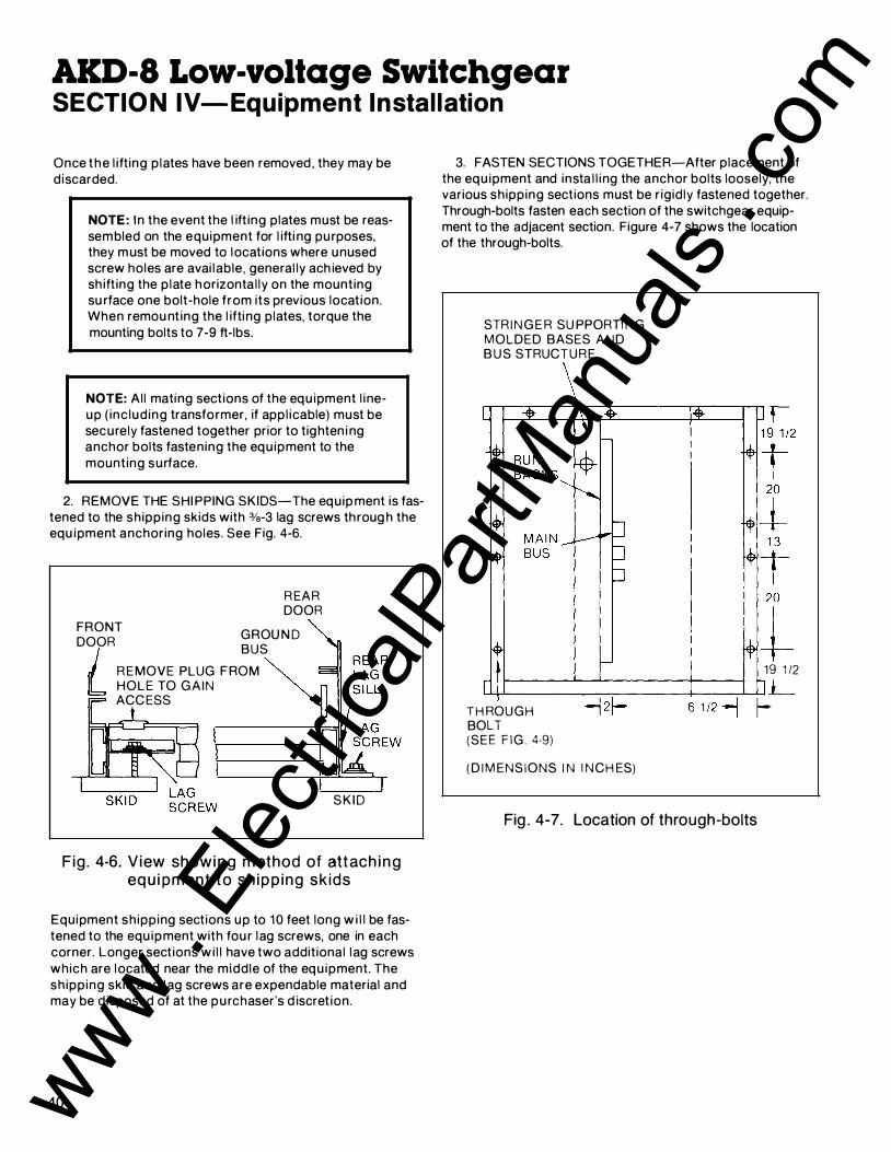
Once the l ifting p lates have been removed , they may be d iscarded.
NOTE: I n the event the l ift ing plates must be reassembled on the equipment for l ifti ng purposes, they m ust be moved to locations where unused screw holes are avai lable, general ly ach ieved by sh ift ing the p late horizontal ly on the mounting su rface one bolt-hole from its previous location. When remou nt ing the l ifting plates, torque the mounting bolts to 7-9 ft-lbs.
NOTE: All mating sections of the equ ipment l i neup ( inc lud ing transformer, if appl icable) must be securely fastened together prior to tighten i ng anchor bolts fastening the equ ipment to the mounting surface.
2. REMOVE THE SHI PPING SKIDS-The equip ment is fastened to the sh ipping skids with %-3 lag screws throug h the equ ipment anchoring holes. See Fig. 4-6.
R EAR DOOR
FRONT GROU N D
DOOR BUS I R EMOVE PLUG F ROM � L HOLE TO GA IN
ACCESS
S K I D
Fig . 4-6. V iew showi n g method of attach i n g equi pment to sh ipp ing sk ids
Equipment sh ipp ing sections up to 1 0 feet long w i l l be fastened to the equ ipment with fou r lag screws, one in each corner. Longer sections wi l l have two additional lag screws which are located near the middle of the equ ipment. The sh ipp ing skid and lag screws are expendable material and may be d isposed of at the purchaser's d iscret ion.
40
3. FASTEN SECTIONS TOGETHER-After placement of the equ ipment and insta l l i ng the anchor bolts loosely, the various shipping sections must be r igidly fastened together. Through-bolts fasten each section of the switchgear equipment to the adjacent section. Figure 4-7 shows the location of the through-bolts.
STR I N G E R SU PPORTI N G MOLDED BASES A N D B U S STRUCTURE
19 1 /2 �--------�-------r----�1__ -j 2f- 1-T H ROUGH BOLT (SEE F I G . 4·9) ( D I M ENSIONS I N I N CH ES)
Fig . 4-7. Location of through-bolts
www . El
ectric
alPar
tMan
uals
. com

SECTION IV-Equipme�nt I nstal lation
Figure 4-8 i l lustrates the installation of the through-bolts. The through-bolts are in the front and rear compartments. The nut and bolt assembly should be tightened with a torque of 25-30 ft-lbs.
T H ROUGH SOL T (3/8-1 6 X 1 ")
FLAT WASHER
N UT
SPLIT LOCKWASH ER
FLAT WAS H ER
Fig . 4-8 . Through-bolt i nstal lation
All of the hardware requ i'red for assembl ing the equ ipment across the sh ipping spl its is furnished with the equipment. If a t ransformer is i ncluded in the l i ne-up of equ ipment, the t ransfo rmer flange should be al igned with the open ing in the side of the transit ion compartment and fastened together using the %-1 6 bolts , nuts and washers suppl ied with switchgear. The fastener assembly should be t ightened with a torque of 25-30 ft-lbs.
4. COMPLETE THE ELECTRICAL INTERCONNECTIONSAfter completing the mechan ical connections between the several sections of equ ipment, the electrical i nterconnections should be completed. This includes the i nstal lation of spl ice p lates for the main bus bars, the neutral bus, and the g round bus in addition to the control and metering c i rcu its.
WARNING: ALL SWITCHGEAR EQUIPMENT MUST BE ADEQUATELY GROUNDED FOR SAFETY. FAI LURE TO GROUND EQUIPMENT PROPERLY MAY RESULT IN SERIOUS INJURY.
Figure 4-9 i l lustrates the general location of the buses that must be spliced across the shipping splits.
N EUTRAL BUS
MAIN
BUS
BUS
Fig . 4-9. Typical location of buses at shipping spl it
41 www . El
ectric
alPar
tMan
uals
. com

AKD-8 Low-voltage Switchgear SECTIO N IV-Eq uipment I nstal lation
The g round bus is mounted d i rectly on the rear upright channels.
NOTE: It is particu larly important that the g round bus be connected fi rst s ince it provides an integ ral g round for a l l the eq u ipment. It must also be connected to the station g round prior to proceeding with the i nstal lation .
A 4/0 AWG cable connector is located i n the bottom of the transition section (or in the i ncoming l ine compartment if a transition sect ion is not i ncluded) for terminating the purchaser's cable connection to ground. The specific location of the station ground connection is shown on the site f loor plan d rawi ng and in the electrical drawings suppl ied with the equ ipment. Al l g rounding of the switchgear shou ld be in accordance with National Electrical Code.
42
CAUTION: TO ACHIEVE THE MINIMUM CONTACT RESISTANCE ACROSS A BOLTED BUS JOINT, IT IS RECOMMENDED THAT THE JOINT CONTACT SURFACES BE COATED WITH A FILM OF G E LUBRICATING G REASE 0282A2048P009. A CAN OF THIS G REASE IS SUPPLIED WITH THE EQUIPMENT. DO NOT PUT GREASE ON THE BOLT THREADS AS THIS WILL AFFECT THE CLAMPING FORCE EXERTED BY THE BOLT.
SPL ICE PLATE
R EAR L STRI N G E R 1 SECTION LI N E
I
Fig. 4-1 0 . P lan view of g round bus spl ice
Figu re 4-1 0 i l l ustrates the i nstal lat ion of the ground bus spl ice plate across a sh ipp ing spl it . I n addit ion to the bolted fastening of the spl ice p late to the two ends of the g round bus, self-tapping %-20 bolts pass through the spl ice p late and ground bus stubs, and thread into the equipment frame. These bolts should be fastened with a torque of 7-9 ft-lbs.
If a GE transformer (rated above 750 kVA) is present in the l ine-up, a ground bar located in the transition compartment, Fig. 4- 1 1 , is provided for connection of the transformer ground pad to the equipment ground termination point.
TRANSFORMER ROU N D
C O N N ECTI ON BAR
Fig . 4-1 1 . Flange opening on a transition section to a G E transformer (above 750 kVA)
As shipped , the g round bar is mounted so it does not protrude beyond the outer su rface of the equ ipment. When the equ ipment is instal led in its fi nal location , the ground bar must be reassembled using the outer bolt holes in the horizontal ground bus spann ing the width of the transition compartment. In th is mount ing location , the offset portion of the g round bar wi l l permit connection to the transformer ground pad with the %-1 3 bolt assembly suppl ied with the switchgear equ ipment. If an optional f loor p late is suppl ied for the transition compartment, it wi l l be necessary to remove the f loor p late to permit relocation of the ground connect ion bar.
www . El
ectric
alPar
tMan
uals
. com

SECTIO N IV-Equipment I nstal lation
Al l bolted bus jo ints should be made using the p roper torque as shown in Table A-1 in Appendix A of this manual .
Transformers not manufactured by General Electric may requ i re special mounting and bus connection hardware.
The neutral bus may be i nsulated from the grounded frame of the switchgear equ ipment; thus, i t is mounted on insu lators throughout the equipment. Instal lat ion of the neutral bus spl i ce plate across a sh ipping spl i t is s imi lar to the ground bar spl ice except that the sp l ice p late is not bolted to the equ ipment frame. Figu re 4- 1 2 i l l ustrates the instal lat ion of the neutral spl ice plate .
STR I N G E R
SPL ICE PLATE
N EUTRA L BUS BAR
Fig. 4- 1 2 . Plan view of neutral bus spl ice i n sta l lat ion
CAUTION: TO ACHIEVE THE MINIMUM CONTACT RESISTANCE ACROSS A BOLTED BUS JOINT, IT IS RECOMMENDED THAT THE JOINT CONTACT SURFACES BE COATED WITH A FILM OF G E LUBRICATING GREASE 0282A2048P009. A CAN OF THrs GREASE IS SUPPLIED WITH THE EQUIPMENT. DO NOT PUT GREASE ON THE BOLT THREADS AS THIS WILL AFFECT THE CLAMPING FORCE EXERTED BY THE BOLT.
rr-... -
I
n n ("'-""--
I ' i I" I I I � I I I I loiP.I I I :Ol I p
I :a l..: 10
[ ....___ �c ¢B "iA
RISSB_BUS --- ------
�
r-"-
sd[ot 01
�
.......- r--"
$8 � �f:l
I I
���--ol I ol 1
I I I
___..._. ---¢B r/JA
; I
I I I
RISER BUS
I I N DIV I DUAL t I N DIVI DUAL J r SECTION SECTION 1 S H I PP ING SPLIT
-....._..
Fig . 4- 1 3 . Rear view of main bus at a shipping split
¢B
¢c
The instal lat ion of the horizontal bus spl ice bars is i ntended to be accomp l ished with bolted joints whether the bus bars are fabricated of either copper or a luminum material . I f the pu rchaser requ i res a welded jo in ing of spl ice bars on an a luminum bus system, it may be ach ieved provided instal lat ion personnel have the ski l l and equipment to perform MIG welding.
Figures 4-1 3 and 4-1 4 i l lustrate the assembly of the main bus splice plates on a bolted bus system. Copper bus systems are normally supplied with flat washers and lockwashers; aluminum systems are supplied with bellevi l le washers at aluminum-to-aluminum or aluminum-to-copper joints.
Figure 4- 1 3 shows the rear view of the main bus area with the installed splice plates indicated with cross-hatching. Figure 4-1 4 shows that a spacer is used both between the bus bars when more than one bar is used per phase (normally the 2500 ampere and larger main bus ratings) and over the outer bars of a single or multiple bar joint.
After assembly of the splice bars and spacers, the 1/2-1 3 bolts should be tightened to a torque of 35-40 ft-lbs.
43 www . El
ectric
alPar
tMan
uals
. com
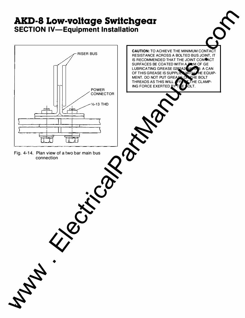
AKD-8 Low-voltage Switchgear SECTION IV-Equipment I n stal lation
RISER BUS
POWER CONNECTOR
%-1 3 THO
Fig . 4- 1 4. Plan view of a two bar main bus connection
44
CAUTION: TO ACHIEVE THE MINIMUM CONTACT RESISTANCE ACROSS A SOL TED BUS JOINT, IT IS R ECOMMENDED THAT THE JOINT CONTACT SURFACES BE COATED WITH A FILM OF G E LUBRICATING GREASE 0282A2048P009. A CAN OF THIS GREASE IS SUPPLIED WITH THE EQUIPMENT. DO NOT PUT GREASE ON THE SOL T THREADS AS THIS WILL AFFECT THE CLAMPING FORCE EXERTED BY THE SOL T.
www . El
ectric
alPar
tMan
uals
. com

,�
SECTION IV-Equipment I nstal lation
NOTE: Spl ice bars are designed to be bolted i n place. I n a n a luminum bus system, it is possible to weld spl ice bars. Do not attempt to do this without contact ing the factory for detai led instructions.
After completing the installation of the main bus splice bars, the joint covers may be mounted and secured by a %-1 6 nylon bolt and polyester flat washer if the bus insulation option has been supplied with the equipment.
5. CONNECT TH E TRANSFORMER SECONDARY-The connection of the transformer secondary to the incoming bus bars in the transition is made using the flexible connect ion straps suppl ied with the transformer. These connections are always bolted joints. There is no provision for a welded joint on equipments suppl ied with a luminum bus bars.
CAUTION: TO ACH IEVE THE MINIMUM CONTACT RESISTANCE ACROSS A BOLTED BUS JOINT, IT IS R ECOMMENDED THAT THE JOINT CONTACT SURFACES BE COATED WITH A FILM OF G E LUBRICATING G R EASE 0282A2048P009. A CAN OF THIS G R EASE IS SUPPLIED WITH THE EQUI PMENT. DO NOT PUT G REASE ON THE BOLT THREADS AS THIS WILL AFFECT THE CLAMPING FORCE EXERTED BY THE BOLT.
The recommended torque for t ighteni ng the %-1 3 bolts fasten ing the transformer connection straps to the i ncomi ng bus bars is 35-40 ft-lbs.
6. INTERCONNECT CONTROL WIRING-Interconnection of control wir ing across shipping spl its is accomplished by connect ing to terminal blocks located i n the cross-section wir ing trough on top of the equipment shown in Fig. 4-1 5.
If terminal b locks are provided , each wire must be attached to the correct point on the terminal block, following the c i rcuit identification number attached to each wire.
Fig . 4- 1 5 . Control wiring is located in the wir ing trough on top of the equipment
45 www . El
ectric
alPar
tMan
uals
. com
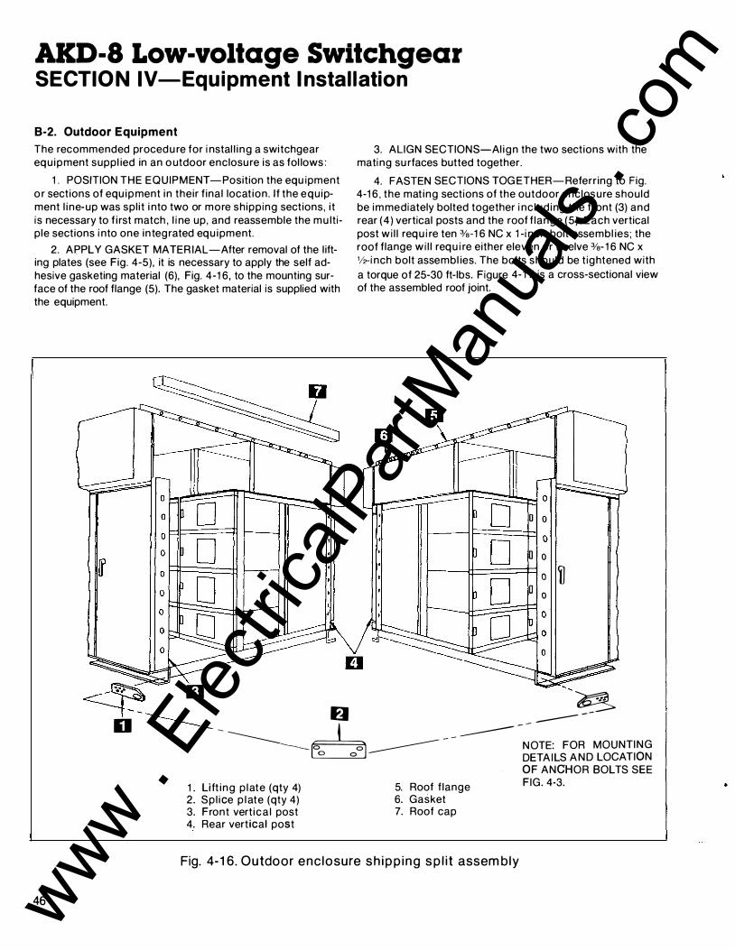
AKD-8 Low-voltage Switchgear SECTIO N IV-Equipment I nstal lation
B-2. Outdoor Equipment
The recommended procedu re for i nstal l i ng a switchgear equ ipment suppl ied in an outdoor enclosure is as fol lows :
1 . POSITION THE EQUIPMENT -Position the equ ipment o r sections of equ ipment in their f inal locat ion. If the equ ipment l ine-up was spl it i nto two or more shipping sections, it is necessary to f i rst match , l i ne up, and reassemble the mu ltiple sections i nto one integrated equ ipment.
2. APPLY GASKET MATER IAL-After removal of the l ifting plates (see Fig. 4-5), it is necessary to apply the self adhesive gasketing material (6), Fig. 4-1 6 , to the mounting surface of the roof flange (5). The gasket material is supplied with the equipment.
3. ALIGN SECTIONS-Al ign the two sections with the mating su rfaces butted together.
4. FASTEN SECTIONS TOG ETHER-Referring to Fig. 4-1 6 , the mat ing sections of the outdoor enclosure should be immediately bolted together i nc lud ing the front (3) and rear (4) vertical posts and the roof f lange (5) . Each vertical post wi l l requ i re ten %-1 6 NC x 1 -i nch bolt assembl ies; the roof flange wi l l requ i re either eleven or twelve %-1 6 NC x 112-i nch bolt assembl ies. The bolts should be t ightened with a torque of 25-30 ft-lbs. Figure 4- 1 7 is a cross-sectional view of the assembled roof joint.
D o 0
D o 1------li======� 0 �
0 0
----� D � -----;. ---:-------- H -- -
46
D � - 6 -------- - -------------- o o ------------ - -
NOTE: FOR MOUNTING o o DETAILS AND LOCATION
OF ANCHOR BOLTS SEE
1 . Lift ing p late (qty 4) 5. Roof f lange FIG. 4-3.
2. Sp l ice p late (qty 4) 6. Gasket 3. Front vert ica l post 7. Roof cap 4. Rear vertical post
Fig. 4-1 6. Outdoor enc losure sh ipp ing sp l it assembly
www . El
ectric
alPar
tMan
uals
. com

SECTION IV-Equipment Instal lation
SELF ADHESIVE GASKETING
ROOF SUPPORT
ROOF
Fig . 4-1 7. Cross-sect ion view of assembled roof jo in t
5 . T I E HOUSING BASES TOGETH ER-Referring t o F ig . 4-1 6, tie the bases of the outdoor housing together us ing the spl ice p late (2) suppl ied with the equ ipment and the bolts which previously secured the l ifting plates ( 1 ) removed after emplacement of the eq u i pment. The nuts are welded to the rear su rface of the base. The bolts shou ld be t ightened with a torque of 45 ft- lbs.
NOTE: There are two spl ice plates requ i red, front and rear of the assembly.
6. INSTALL THE ROOFCAP-The roofcap (7), Fig. 4- 1 6, should be instal led over the sealed and fastened roof flange assembly (5). The roof cap is secu red in place with two '14-20 NC x '12-inch th read form i ng bolts, each at the front and the rear ends of the roof cap. These bolts should be t ightened with a torque of 7-9 ft-lbs.
7. CONNECT TRANSFORMER FLANGE-If a transformer is i nc luded in the eq uipment l i ne-up, the flange should be connected to the switchgear open ing us ing the gasket material , cement, and fasten ing material suppl ied with the swi tchgear equ ipment.
8. JOIN SECTIONS TOGETH ER-The switchgear eq u ipment with i n the outdoor enclosu re should be jo ined to its mat ing sections in the manner described for i ndoor equ ipment i n Section 4.2, Paragraph B-1 , Step 3, Page 40.
9. MAKE ELECTRICAL INTERCONNECTIONS-The instal lation of bus spl ice plates for the main horizonal , neutral and g round buses should be done in accordance with the i nstruct ions for indoor equ ipment, Section 4.2, Parag raph B-1 , Step 4, Page 41 .
1 0. CONNECT THE TRANSFORMER SECONDARY-The instal lation of the transformer connection straps to the incoming bus should be done in accordance with the instructions for i ndoor equ ipment, Section 4.2, Paragraph B-1 , Step 5, Page 45.
1 1 . INTERCONNECT CONTROL WIR ING-The i nterconnection of control wir ing across sh ipping spl its should be done in accordance with the instructions for i ndoor equ ipment, Sect ion 4.2, Paragraph B-1 , Step 6, Page 45.
FRONT VERTICAL POST
RUBBER DOOR SEALS
Fig. 4- 1 8 . Door seals
1 2 . SEAL SMALL OPENINGS-After completion of the sh ipping spl i t assembly, any smal l open ings should be sealed with GE Clear S i l i cone Cau lk ing Cement.
C. Anchoring Switchgear Equipment Correct anchoring of the switchgear equ ipment to the foundation is very important. After completion of reassembly of the equ ipment at the sh i pping spl its, the equipment anchoring procedu re should be completed .
47 www . El
ectric
alPar
tMan
uals
. com

AKD-8 Low-voltage Switchgear SECTIO N IV-Equipment I nstal lation
C-1 . I ndoor Equipment
1 . ANCHORING BY ANCHOR BOLTS-Indoor equ ipments are normally secured to their f inal mounting surface by anchor bolts threaded i nto the embedded channel s i l ls. The bolts were loosely th readed into p lace before reassembl ing the equ ipment sh ipp ing spl its and connecting to the closecoupled transformer, if appropriate.
The anchor bolts should now be t ightened with a torque of 35-40 ft- lbs.
2. ANCHORING BY WELD-An alternate method of anchoring the equ ipment to its foundation is to weld the equ ipment to floor si l ls (or the floor itself if constructed of steel ) . Several methods, shown on Fig. 4-1 9, are avai lable to the purchaser for weld ing the eq u ipment to the channel s i l ls.
ELEVATION
P LAN V I EW
1 . Channel s i l l
a . The front o f the equipment is attached t o the embedded channel s i l ls ( 1 ), Fig. 4- 1 9, by two 3/, s- inch f i l let welds (2). I t is recommended that two welds, each 2112 i nches long (min . ) , be used for each section to f i rmly tie the bottom width post (3) to the channel s i l l .
b . The rear of the equipment may be anchored by one of three p rocedu res :
• The f i rst method is by p lug welds (4) . F ig. 4- 1 9, using the anchor bolt ho les in the rear s i l l angle (5). The p lug weld should receive a m in imum Va-i nch bead around the entire c i rcumference of the anchor bolt hole.
• A second method of secu ring the rear s i l l angle (5) to the channel si l l (1 ) is the use of two l i near f i l let welds (2) for each sect ion. It is recommended that each weld be 2V2
i nches long (min . ) with a 3/, s-i nch f i l let (min . ) .
OPTIO NAL M ETHOD
D fJ
2. 3/16-inch f i l let weld 3. Front width post 4. Plug weld in anchor bolt hole 5. Rear s i l l angle 6. Rear width post
Fig. 4-1 9. I ndoor equipment weld anchoring
48 www . El
ectric
alPar
tMan
uals
. com

SECTION IV-Equipment I nstal lation
• A th i rd method for anchor ing the rear o f the equ ipment is to remove the rear s i l l angle (5) from the switchgear and weld the rear bottom width post (6) to the channel s i l l ( 1 ) . These welds (2) should , l i ke the front welds, have a 3/1s- inch (min . ) f i l let and each have a min imum length of 2% i nches.
C-2. Outdoor Equipment
Outdoor equ ipments are anchored after reassembly of the separately sh i pped sections. The fou r anchor bolts should be tightened with a torque of 45·55 ft- lbs.
CAUTIO N : IF THE EQUIPMENT IS TO BE SUBJECTED TO OPERATIONAL OR ENVIRONMENTAL (SEISMIC) SHOCK LOADING, TH E FACTORY MUST BE CONSU LTED FOR ANCHORING REGOM M ENDATIONS.
D. B u sway Con nections Busway runs must be a l igned with open i ngs i n the equ ipment and connected to the mati ng components electrically and mechan ical ly. A collar is mounted on the top of the equ ipment cable compartment to which is bolted the busway housing. See F ig . 4-20. The %-20 NC bolts, washers, and nuts for this mechanical connection are suppl ied with the
TOP OF SWITC H G E A R FRAM E � T O P E N T R Y SHOWN
�.____� G ROUN D --
T
� REAR O F 1 ' SWITC H G E A R
RISER BUS
Fig. 4-20 . Spectra Series T M Busway mounting (front -entry)
busway stub. The bolts should be t ightened with a torque of 7-9 ft-lbs.
The power conductors in the busway stub are designed to bolt d i rectly to power connector blocks mounted on the switchgear riser bus bars. These connections are made with %-1 3 NC bolts suppl ied with the switchgear equ ipment.
CAUTION: TO ACHIEVE THE MINIMUM CONTACT RESISTANCE ACROSS A BOLTED BUS JOINT, IT IS R ECOMMENDED THAT THE JOINT CONTACT SURFACES BE COATED WITH A FILM OF G E LUBRICATING GREASE 0282A2048P009. A CAN OF THIS G REASE IS SUPPLIED WITH THE EQUIPMENT. DO NOT PUT GREASE ON THE BOLT THREADS AS THIS WILL AFFECT THE CLAMPING FORCE EXERTED BY THE BOLT.
The recommended torque for t ighten ing the %-1 3 NC bolts connected the busway stub conductions to the r iser bus power connectors is 35 -40 ft- lbs.
E. Control Wire Connections For external control wir ing , refer to F ig . 4-21 for switchgear cable area d imensions, and connect the control wi res to the switchgear section as fol lows:
1 . When control cond u its enter the switchgear from below, they should not extend more than one inch above the
62 B
+ -- - - - - -------/ 5
SEE NOTE ..i_ - '---'-+-----' MAXIMUM AVAILABLE SPACE FOR CABLES
- - - - - - - -FRONT
NOTE: BUS COMPARTMENT BARRIER LOCATION - WHEN THIS OPTION IS PROVIDED, IT REDUCES AVAILABLE SPACE FOR CABLES ABOVE BY (5) INCHES.
- - -
<n .... 6 "' a: 0 I (.) � A ;, SECTION DEPTH 0 a: 0 u.. <n w 6 I
EquDopth "A" 60" or 6T
With Fused AKRU-50 6T or 74�
With Fused AKRU-50 74" Deep Except With AKRU-50
Fig . 4-21 . Floor plan and cable entry spaceindoor AKD-8
49 www . El
ectric
alPar
tMan
uals
. com

AKD-8 Low-voltage Switchgear SECTIO N IV-Equipment I nstal lation
floor. The control wires may b e pu l led through the condu its before or after the switchgear is instal led.
2. Route the control wi res from the condu its through the wir ing t rough (cross-hatched area-2" x ?"-shown on Fig. 4-24) at the side of the cable compartment. Connect the cables to the termi nal blocks in accordance with the con nect ion diagrams for the equ ipment.
3. If the control condu its enter from above, dr i l l the top cover with i n the avai lable space ind icated. See Fig. 4-21 . Contro l wi res should be routed to the wir ing trough and connected to the termi nal blocks as described p reviously.
F. Power Cable Con nections Connect the mai n cables to the main l ugs. Before any main cable connections are made, the cables should be identified to i nd icate their phase relationsh ip with the equ ipment. Adequate electrical and mechan ical clearances must be provided between conduit , cables, and bus. Where the cables enter the sect ion, they can be lashed to optional cable su pports at the rear of the cable compartment as requ i red. (See Fig. 3-22.)
Mechanical cable terminals are normal ly inc luded with the switchgear (compression terminals are suppl ied when ordered) and are mounted at the ends of the breaker runbacks in the cable compartment. Carefu l ly fol low the cable manufactu rer's recommendations for i nstal lation of cable.
Insta l l the cables in the proper path to the terminals, using temporary lash ing if requ i red. Cut the cables to the proper length . Strip the i nsu lat ion to the desi red d i mension, bei ng carefu l not to damage any strands.
For copper cables, coat the wires with GE lubricating grease 0282A2048P009, insert the cables into the terminals, and tighten the set screws in accordance with torque values shown in the torque value table for cable terminals in the addendum of this manual. See Appendix A, Table A-1 .
50
CAUTION: THE TORQUE VALUES SHOWN IN THE TABLE ARE FOR DRY THREADS ONLY. DO NOT GREASE OR OTH ERWISE LUBRICATE THE THREADS ON THE CABLE TERMINALS AS THIS WILL PERMIT OVERTIGHTENING OF THE SCREW AND CAUSE POSSI B LE DAMAG ETO THE TER M I NAL OR CABLE.
For a luminum cables, wire brush the wire strands thorough ly. Immediately after wire brush ing , coat the cable strands with a qual ity oxide inh ib it ing compound such as Penetrox A. I nsert exposed wi res i nto the termi nals and tighten the set screws in accordance with val ues shown in the torque Table A-3 in Appendix A of th is I nstruction Book.
CAUTION : THE TORQUE VALUES SHOWN IN TH E TABLE ARE FOR DRY THREADS ONLY. DO NOT GREASE OR OTHERWISE LUBRICATE THE THREADS ON THE CABLE TERMINALS AS TH IS WILL PERMIT OVERTIGHTENING OF THE SCREW AND POSSIBLE DAMAG E TO THE TERMINAL OR CAB LE.
This should resu l t in the oozing of compound material from between ind ividual strands. Wipe off any excess compound.
Bolt the cable terminal connectors to the ends of the bars in the cable compartment. A non-oxidizing grease, such as G E lubricating grease 0282A2048P009 furnished with each equipment, should be used at these connection surfaces. The bolts should be tightened with a torque of 35-40 ft-lbs.
Lash the cables securely to the cable support, if present, to take their weight off the runbacks and to brace them against short circuit forces in the event of a fault.
G. Relays and Control Devices Remove al l blocking on relays and devices as shown in the instructions accompanyi ng the devices.
www . El
ectric
alPar
tMan
uals
. com

SECTION IV-Equipment Instal lation
H . Breaker Hoist H-1 . Indoor Equipment
F igure 4-22 shows the breaker hoist assembled on an i ndoor switchgear equ ipment. When suppl ied with i ndoor eq u ipment, the hoist is sh i pped i n a separate carton completely assembled, Fig. 4-23.
Before attempt ing to i nstal l the hoist assembly on the switchgear eq uipment, it is necessary to remove the runner gu ide from the hoist carriage as shown in Fig. 4-24. Do not d ispose of th is g u i de si nce it must be reinstal led after mount ing the hoist on the equ ipment.
NOTE: Maximum recommended l ift i ng capacity is 700 lbs.
Fig. 4-22. Breaker hoist assembly on i ndoor switchgear
Fig. 4-23. Carton conta in ing breaker l ifting device
Fig . 4-24 . Removal of hoist runner guide
51 www . El
ectric
alPar
tMan
uals
. com

AKD-8 Low-voltage Switchgear SECTION IV-Equipment I nstal lation
The hoist shou ld be l ifted i nto position on top of the switchgear so that the end with the s ingle rol ler is toward the rear of the equ ipment. Fig. 4-25.
Fig. 4-25 . Position ing of hoist on top of switchgear
The rear wheel can then be hooked under the channel and . the front wheels can be positioned on the fronttrack. See Fig. 4-26. The retai n ing angle at the rear should then be reassembled . Stop cl ips are provided at each end of the front track to p revent the hoist from rol l i ng off the ends of the track.
52
. F ig . 4-26. Rear wheel hooked under channel and front wheels on front track
Fig . 4-27. - Replacing the runner after completion of hoist i nstallation
Fig. 4-28. Removing the bracket locking the hoist dol ly
After completion of the hoist i nstal lation , replace the runner gu ide, F ig . 4-27, and remove the bracket, Fig . 4-28, locking the hoist do l ly on the carriage.
If the equ ipment has been sh ipped in sections, run the hoist carriage over the assembled sh ipp ing spl i t to check the al ignment of the hoist rai l and runner. If necessary, adjust the rai l and/or runner for smooth operation of the rol lers on the hoist carriage .
www . El
ectric
alPar
tMan
uals
. com

SECTION IV-Eq uipment I nstal lation
H-2. Outdoor Equipment
When the hoist i s provided with outdoor eq uipment, it is shipped mou nted and secu red in p lace. The shipping supports at e ither end of the hoist movable track must be removed. To free the ho ist dol ly, remove the reta in ing cl ip used to keep it i n p lace during sh ipment, as shown i n Fig. 4-29.
I. Final I n spection Make a f i nal i nspection to see that no tools, construction materials, or other fore ign matter have been left in the switchgear eq u ipment.
Fig. 4-29 . Removing retain ing cl ip to free hoist dolly
53 www . El
ectric
alPar
tMan
uals
. com

AKD-8 Low-voltage Switchgear SECTIO N V-l nstal l ing and Removing Circuit B reakers
5.1 -General A. I n spection and Preparation o f Circuit
B reakers Before i nstal l i ng , operati ng , or removing a ci rcuit breaker, refer to the breaker instruction manual for p reparation, i nspection, and test. Check thorough ly for damaged or loose parts and for any d i rt or fore ign matter which may be in the breaker. Be sure that a thin film of G E lubricating grease 0282A2048P009 is present on primary disconnects of the switchgear before installing the breaker.
B. Circuit B reaker I nsta l lation To i nsta l l a circuit breaker, proceed as fol lows:
1 . Before i nstal l i ng a breaker, check the t ig htness of the bolted jo ints in the primary d isconnect bars. Refer to torque value table, Appendix A, Table A-1 , in this manual for the proper torq ue values. Also check the contact areas on each primary disconnect bar or cluster of fingers for foreign matter that may have accumulated. Clean these areas if necessary. Be sure that a thin fi lm of GE lubricating grease 0282A2043P009 covers the contact areas before putting a breaker in the compartment.
2. Check to see that the breakers match their respective compartments. Each breaker is assigned a part or mark number. Th is n umber is shown on the breaker sheets of the summary, the front view drawi ngs, the breaker nameplate, and on the identif icat ion card on the breaker sh ipping carton .
3. To locate the breaker in the proper compartment, refer to the breaker location l ist on the front view drawing . F ind the proper breaker by the identif ication card on the breaker carton or the mark nu mber on the breaker nameplate. All identical breakers wil l have the same mark nu mber.
F R O N T OF � CO M P A R T M E N T
P I N I N F R O N T PO S I T I O N A S LO T
R I G H T S I D E
RAIL
Fig. 5-1 . Section view of rejection pin mounting used in AKR-30/30H, AKR-50/50H , and AKRT-50 compartments
54
C. Rejection Feature Drawout breakers of the same type and rat ing are interchangeable i n their equ ipment compartments. Drawout breakers of d i fferent frame size, type, or short-circuit rat ing are i ntentional ly made non-i nterchangeable to prevent i nsert ing the wrong type breaker i nto a drawout compartment ; u n ique " rejection hardware" is affixed to each breaker and its compartment. When the wrong type breaker is placP1 on the compartment drawout rai ls, the bracket on the breaker and the pin on the rai l assembly do not mate, and thus prevent the breaker from seat ing on the rai ls.
EXCEPTIO N : A breaker with a h igh short-ci rcu it �at ing wi l l fit a compartment keyed for a lower short-circuit rati ng . For example, a AKR-30H breaker can be inserted into an AKR-30 compartment. An AKR-30 breaker, however, wi l l be rejected by an AKR-30H compartment.
F igu res 5-1 and 5-2 i l l ustrate the rejection pin mou nti ng used in AKR-30/30H, AKR-50/50H and AKRT-50 compartments.
The AKR-75 and 1 OObreakers and their fuse carriages are equipped with d i fferent style brackets which mate with p ins on the d rawout rai l assembly as shown in F igs . 5-3 and 5-4.
Fig . 5-2. Photograph of rejection pin mounting used in AKR-30/30H , AKR-50/50H, and AKRT-50 compartments
www . El
ectric
alPar
tMan
uals
. com

SECTION V-l nstal l ing and Removing Circuit Breakers
•
• t + • -$-
l�-+�---<.; ft------t-' _+c.;J + LL+�' _ __,\'" I ±J
\..'--___ ) '-'-----LEFT-HAND RIGHT-HAND TRAY ASSEMBLY TRAY ASSEMBLY
F ig . 5-3. Sect ion view of drawout rai l assembl ies used i n AKR-75 and AKR-1 00 compartments
Fig. 5-4. Photograph of drawout tray assembly used in AKR-75 and AKR-1 00 compartments
NOTE: If a breaker is rejected by the d rawout rai ls, check the breaker type and rat ing agai nst the job d rawing .
The complete rejection p in pattern code is inc luded in Appendix B .
5.2- l nsta l l i ng the AKR Circuit Breakers
A. Prio r to I n stallation Prior to l ifti ng a breaker to its i ntended compartment locat ion, observe the fol lowing precautions:
PRECAUTIONS
1 . Check the compartment to ensu re that it is free of foreign objects.
2. Verify that the breaker is the correct type for that compartment.
3. Ensure that the breaker is OPEN. 4 . Apply a thin fresh coat of G E lubricating grease
0282A2048P009 to the breaker's primary and secondary disconnects.
5. Ensure that the racking on the breaker are correctly positioned for initial engagement with the pins in the compartment. To do this, insert the racking handle and rotate it fully counterclockwise.
B. I n stallation Procedures To instal l the AKR c i rcu it breakers, p roceed as fol lows
1 . Carefu l ly place the breaker in front of the section in which it is to be instal led. See F ig . 5-5.
2. Open the breaker compartment door by squeezing the p inch-type latch.
3. Using the switchgear ho ist or a su itable l i fti ng mechanism (and spreader rig for AKR-30/50 and AKRU-30/50 breakers), raise the breaker about one-half i nch above the elevation of the rai ls. See Fig. 5-6. Insert the spreader bar hooks in the forward slots for non-fused AKR-30/50 breakers and in the rear slots for fused AKRU-30/50 models.
WARNING: DO NOT STAND UNDER THE CI RCUIT B REAKER DURING THE HOISTING OPERATION.
55 www . El
ectric
alPar
tMan
uals
. com

AKD-8 Low-voltage Switchgear SECTIO N V-l nstal l ing and Removing Circuit B reakers
56
Fig. 5-5. Pay out hoist cable. Attach hoist to circuit breaker
Fig. 5-6. Hoist breaker about one-half i nch above rails
Fig . 5-7. Pull rai ls out completely from the c ircuit breaker compartment
Fig . 5-8. Lower the breaker onto locat ing p ins on the tray. Remove the hoist cable.
www . El
ectric
alPar
tMan
uals
. com

SECTION V-l nstal l ing and Removing Circuit Breakers
CAUTIO N : WHEN USING TH E SWITCHG EAR HOIST, DO NOT UNWIND THE CABLE COMPLETELY FROM THE DRUM. TO LIFT TH E B REAKER, TURN THE HOIST OPERATING CRANK CLOCKWISE. TO LOWER THE B REAKER, TU RN THE HOIST OPERATING CRANK COUNTERCLOCKWISE.
4. Pu l l the rai ls out completely from the circu it breaker compartment, Fig. 5-7. Due to a d i fferent drawout mechan ism for the larger AKR-75/1 00 breakers, refer to Sect ion 5.3 for specif ic detai ls on mounting these breakers on their d rawout trays.
5. Slowly lower and gu ide the breaker to al low the breaker mounting p ins to d rop i nto the slots in the rai ls . See Fig. 5-8. Remove the l i ft ing device. Fai l u re to seat properly may i ndicate the breaker is being barred by the reject ion p ins i n the d rawout rai ls. With the AKR-30/50 or AKRU-30/50 breakers, the breaker is now completely mated to the drawout mechan ism ( rai ls). With the AKR-75/1 00 breakers, i t is necessary to bolt the breaker to the d rawout tray.
6. Push the breaker i nto the compartment unt i l it reaches the rai l stops. See Fig. 5-9. This is the DISCONNECT position . At this point, the racking arms must be posit ioned to engage the f ixed racking p ins in the compartment.
7. Close the compartment door.
8 . Engage the racking handle. With the AKR-30/50 and AKRU-30/50 breakers, the racking handle is engaged by push ing the trip button in the breaker escutcheon , s l id ing the cover below it to the r ight , and i nsert ing the handle on the jackshaft. See Fig. 5-1 0.
9. Rotate the handle clockwise as far as it wil l go. Toward the end, a h igh force w i l l be felt as the d isconnect f ingers on the b reaker engage the stat ionary studs. Several turns later, the stop wil l be encountered. The posit ion ind icator on the side of the breaker escutcheon wi l l d isp lay the word CONNECTED, f lush w ith the breaker door.
Fig . 5-9. Push the breaker in completely. Close the door.
Fig. 5-1 0 . Engage the racking crank with the racking screw (AKR-30/50)
57 www . El
ectric
alPar
tMan
uals
. com

AKD-8 Low-voltage Switchgear SECTIO N V-l nstal l ing and Removing Circuit Breakers
5.3- Mou nti ng the .AKR-75/1 00 Circuit Breaker on the Drawout Tray
WARNING : DO NOT STAND UNDER THE CIRCUIT B REAKER DURING THE HOISTING OPERATION.
CAUTION: WHEN USING THE SWITCHGEAR HOIST. DO NOT UNWIND THE CABLE COMPLETELY FROM THE DRUM. TO LI FT THE BREAKER, TURN THE HOIST OPERATI NG CRANK CLOCKWISE. TO LOWER THE BREAKER, TURN THE HOIST OPERATING CRANK COUNTERCLOCKWISE.
To mount the AKR-75/1 00 c ircuit breaker on the drawout tray, p roceed as fo l lows :
1 . Pu l l the drawout tray a l l the way out to its WITHDRAWN l i mit .
2. Lower the breaker over the tray unt i l it is about one-half inch above the two dowel pins on the tray. Push the breaker back i nto the compartment unt i l the rear bottom flange of the breaker rests agai nst the gu ides beh ind the dowel p ins.
3. Slowly lower and gu ide the breaker onto the tray so the holes in the rear f lange fit over the two dowel pi ns. When correct ly posit ioned on the dowel p i ns. the breaker"s rear and side bottom flanges wi l l rest f irmly on the tray.
NOTE: Fai l u re to seat properly may ind icate the breaker is being barred by the rejection p ins in the d raw out rai ls.
4. Secure the breaker to the tray by i nsert ing and t ightening two %-inch hex head screws i nto the front holes of its side flange as shown i n F ig . 5-1 1 .
5. Push the breaker i nto the compartment unt i l the spri ng discharge stop engages, prevent ing further movement. This is the DISCONNECTED posit ion. At th is point , the racking cams are positioned to engage the fixed racki ng pins i n the compartment, ready to beg in the rack i ng motion.
58
Fig . 5-1 1 . Securing AKR-75/1 00 breakers to d rawout tray
Fig . 5- 1 2. Release lever used on manual ly operated breaker models in place of spring d ischarge interlock
www . El
ectric
alPar
tMan
uals
. com
SECTION V-l nstal l ing and Removing Circuit Breakers
NOTE: Manual ly operated breaker models do not employ a spr ing discharge i nterlock. It is unnecessary because their operat ing mechanism never stat ical ly posit ion the springs i n a fu l ly charged state. However, to provide the necessary means for mechanically securing the breaker in the DISCONNECTED position , a position stop is employed. It has a release lever (F ig . 5-1 2) marked " Push to Withd raw" and is located in the same place as the spring discharge release lever on electrical ly operated breakers.
5.4- Removing the A KR-30/50/T50 and A KRU-30/50 Circuit Brea kers
WARNING: DO NOT STAND UNDER THE CIRCUIT B REAKER DURING THE LOWERING OPERATION.
CAUTIO N : WHEN USING THE SWITCHGEAR HOIST , DO NOT UNWIND THE CABLE COMPLETELY FROM THE DRUM. TO LIFT THE BREAKER, TURN THE HOIST OPERATING CRANK CLOCKWISE. TO LOWER THE BREAKER, TURN THE HOIST OPERATING CRANK COUNTERCLOCKWISE.
To remove the AKR-30/50/T50 and AKRU-30/50 c i rcuit breaker, proceed as fo l lows:
1 . With the door closed and latched , tr ip the breaker.
2. I nsert the racking handle and rotate it counterc lockwise unt i l the breaker travels from CONNECTED through TEST to the DISCONNECTED posit ion , as i nd icated by the jackscrew coming to a stop. This operation should be performed with the door closed. If the breaker closing spring is ful ly charged, it w i l l be automatically d i scharged a few turns before the end of the rack ing act ion .
3. Open the compartment door. Pu l l the breaker out to the l imit of rai l travel . This is the WITHDRAWN position .
4. Before proceed ing , v isual ly check the breaker's spr ing charge and close ind icators to verify that breaker is open and the springs are d ischarged.
5. Attach the l ift ing dev ice and ho ist the breaker u nt i l its mounting pins clear the rai l 's slots.
6 . Push the d rawout rai l s back i nto the compartment.
7. Swi ng the breaker forward u nt i l the primary disconnects clear the compartment.
8. Lower the breaker onto a f lat su rface free of protrusions that cou ld damage the breaker's i nternal parts.
5.5-Removing the A KR-75/1 00 Circ u it Breake rs
WARNING: DO NOT STAND UNDER THE CIRCUIT BREAKER DURING THE LOWERING OPERATION.
CAUTIO N : WHEN USING THE SWITCHGEAR HOIST, DO NOT UNWIND THE CABLE COMPLETELY FROM THE DRUM. TO LIFT THE BREAKER, TURN THE HOIST OPERATING CRANK C LOCKWISE. TO LOWER THE BREAKER, TURN THE HOIST OPERATING CRANK COU NTERCLOCKWISE.
To remove the AKR-75/1 00 c i rcu i t breakers, proceed as fo l lows :
1 . With the door closed and latched , tr ip the breaker.
2. Insert the rack ing handle and rotate it cou nterclockwise u nti l the breaker travels from CONNECTED through TEST to the DISCONNECTED posit ion , as ind icated by the jackscrew coming to a stop. Th is operation should be performed with the door c losed.
3. Open the door. On electrical ly operated breakers, dep ress the spr ing d ischarge lever (F ig . 5-1 2) to discharge the breaker's c losing springs. Wh i le ho ld ing th is lever depressed, pu l l the breaker a l l the way out to its WITHDRAWN position . On manual ly operated breakers, t h is release lever i s labeled "PUSH TO WITHDRAW. "
4 . Before proceed ing , visual ly check the breaker's spring charge and close ind icators to verify that the breaker is open and the spri ngs are discharged .
5. Remove the two %-i nch hex head screws (Fig. 5-1 1 ) which fasten the breaker to the compartment tray.
6. Attach the l i ft ing device to the cutout notches in the top wraparound frame of the breaker, usi ng care to prevent damage to the wir ing.
7. L ift the breaker approximately one-half inch off the dowel p ins . Push the tray back i nto the compartment.
8. Swing the breaker forward unt i l the primary d isconnects clear the compartment. Lower the breaker onto a flat su rface free of protrusions that cou ld damage the breaker's internal parts.
59 www . El
ectric
alPar
tMan
uals
. com

AKD-8 Low-voltage Switchgear SECTIO N V-l nstal l ing and Removing Circuit B reakers
5.6- l nstal l ing and Removing AKRU-30/50 Fused Circuit B reake rs
Except for the open fuse lockout device and the integ ral ly mounted fuses on the upper studs, the AKRU-30 and -50 breakers are identical to the unfused AKR-30 and -50 models. To compensate for added weight of the fuses and their mounting supports, the l ifti ng hoist spreader bar hooks must engage the rear (away from escutcheon) slots on the breaker frame. Later production breakers have one slot on each side located for correct balance. The procedu ral steps for i nstal ling and removing the AKRU-30/50 breakers from the AKD-8 switchgear equ ipment are the same as that described i n paragraph 5.4 for non-fused AKR-30/50 breakers.
5.7- l nstal l ing Fuses i n A K RU-30/50 Circuit B reakers
The fuses on AKRU-30/50 breakers are mounted on the l ine side primary d isconnect CONDUCTORS. The Class L fuses are mounted as shown i n Fig. 5-1 3. Other than the 800A size, wh ich has a single mount ing hole per tang , each Class L fuse tang has two holes sized for one-half inch bolts.
Appendix G i nc ludes a tabu lation of the range of fuse sizes avai lable for these breakers inc lud ing catalog numbers of both General E lectric CLF and Gould Shawmut Fuses.
Class J fuses rated 300 through 600A have one mounting hole per tang . The 300, 350 and 400A sizes requ i re copper adapter bars as shown in Fig. 5-1 4.
60
Fig. 5-1 3 . Typical mounting for C lass "L" fuse on AKRU-30/50 breakers
ADAPTER BARS (COPP E R)
Fig . 5- 1 4. M ount i ng for 300, 350, and 400-ampere C lass " J " fuses on AKRU-30 breakers
A special fuse is avai lable for use with AKRU-50 breakers. This fuse provides a melt ing ti me-cu rrent characteristic that coord inates with 1 600A trip devices. Compared physically with a 2500A, NEMA Class L fuse, the special fuse is more compact (shorter) and its tangs are specia l ly config u red and offset to ach ieve the requ i red pole-to-pole fuse spacing . A special primary d isconnect assembly mou nts d i rectly on the outboard tang of the fuse. Because of their un ique mount ing provisions, the fol lowing procedure should be adhered to when replacing these fuses (F ig . 5-1 5) :
1 . Specia l 2500A fuse 4. Upper barrier 2. D isconnect key 5 . Primary d isconnect 3. Heat s ink
Fig . 5-1 5 . AKRU-50 breaker with special 2500-ampere fuse
www . El
ectric
alPar
tMan
uals
. com

SECTION V-l nstal l ing and Removing Circuit B reakers
1 . Remove the primary d isconnect assembly from the fuse tang. This is accompl ished by f i rst l oosen ing the two keys (2), F ig. 5-1 5, v ia their hold ing screw and pu l l i ng them upward and out. After the keys are removed , pu l l the disconnect assembly off the end of the fuse tang .
6. Instal l the new fuse by reversing the disassembly procedure. Ensure that the mating faces of the fuse and heat s ink are clean.
NOTE: This removal does not distu rb the d isconnect's clamping force adj ustment.
2. Remove the upper barrier (4).
3. Detach the i nboard end of the fuse by removing the two V2-1 3 NC bolts. A ratchet and socket with a short extension wi l l be req u i red.
4. Remove the heat sink (3).
5 . Remove the fuse.
0
CAUTIO N : WHEN REPLACING THE FUSE IN THE RIGHT POLE (PLAN VI EW) OF THE BREAKER, NOTE PARTICULARLY THAT THIS FUSE IS MOUNTED DIFFERENTLY FROM THE OTHER TWO FUSES. AS SHOWN IN FIG. 5-1 6, FOR THIS PHASE THE FUSE IS ROTATED 1 80 DEGREES ABOUT ITS AXIS SO THAT ITS INBOARD TANG IS POSITIONED BENEATH THE BREAKER STUD. THIS TANG IS OFFSET WITH RESPECT TO THE OPPOSITE END, (F IG. 5-1 7) , SO THAT ROTATING THE FUSE DOES NOT AL TER THE POSITION OF THE PRI MARY DISCONNECT.
FRONT OF BREAKER FOR THIS POLE O N LY, FUSE IS ROTATED 1 80 ° TO POSIT ION TANG BEN EATH BREAKER STU D
FUSE TANGS POSITI O N ED ON TOP O F BREAKER STU D
TANG BOLT HOLES IN USE
� -� · @ L _ _ _ _ _j
2500A FUSE IN USE
G F9F2500AK OR
A4BX2500GE
PRI MARY D ISCO N N ECT ASSEMBLY MOU NTS D I RECTLY ON OUTBOARD FUSE TA NG
Fig . 5- 1 6. P lan view of AKRU-50 breaker showing 2500-ampere fuse tang positions
61 www . El
ectric
alPar
tMan
uals
. com

AKD-8 Low-voltage Switchgear SECTIO N V-l nstal l ing and Removing Circuit B reakers
B R E A K E R S T U D
H EAT S I N K
F ig . 5-1 7. Mount ing for specia l 2500-ampere fuse on AKRU-50 breaker
5.8-l nstal l ing and Re moving Fuse Rollout Eleme nts (FR0)-30-I nch Wide Compartme nts
The FRO is racked into and out of its compartment just l i ke a breaker. However, the fuse and breaker compartments each are equ ipped with keylocks to prevent racking the FRO when its associated breaker is closed. The FRO also ut i l izes a reject ion p in scheme sim i lar to that used on AKR-75/ 100 breakers, to prevent instal lation of an incorrect FRO.
Al l FRO models feature a h i nged , perforated steel screen panel i n front of the fuses as shown in F ig . 5-1 8. This panel can be opened to al low access to the fuses, Fig. 5-1 9, only when the FRO is in the WITHDRAWN position . In al l other positions, an interference p late attached to the right side of the panel prevents it from being opened . Operation of the breaker compartment keylock is the same for al l models. With the breaker open, the key can be removed ; this extends the lock bolt, thereby mainta in ing the breaker in a trip-free state whi le in the CONNECTED posit ion. The breaker can be racked at w i l l regardless of the keylock position .
62
F ig . 5-1 8. Fuse ro l lout carr iage (FRO) show i n g h inged , perforated steel screen panel
F ig . 5-1 9. View showi n g perforated panel open to al low easy access to fuses
The FRO compartment is KEY INTERLOCKED with the associated breaker i mmed iately above. The FRO racking mechan ism is locked i n an i noperative posit ion unt i l a key is i nserted i n the FRO key i nterlock, Fig. 5-20. The key is captu red in the breaker compartment KEY INTER LOCK, Fig. 5-21 , and is not released unti l the breaker is tr ipped .
www . El
ectric
alPar
tMan
uals
. com
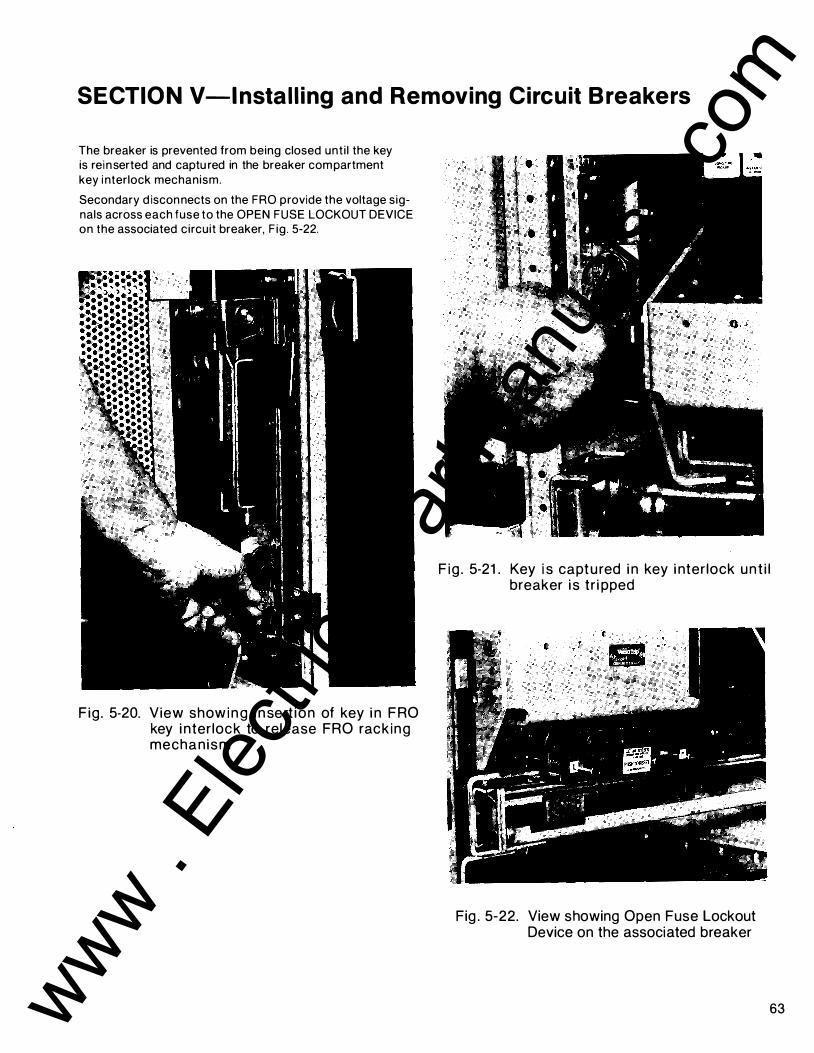
SECTIO N V-l nstal l ing and Removing Circuit B reakers
The breaker is prevented from being closed unti l the key is reinserted and captu red in the breaker compartment key interlock mechanism.
Secondary d isconnects on the FRO provide the voltage signals across each fuse to the OPEN FUSE LOCKOUT DEVICE on the associated circuit breaker, F ig . 5-22.
Fig . 5-20. View show i n g i n sert ion of key i n FRO key i nter lock to release FRO rack ing mechan ism
F ig . 5-21 . Key i s capt u red i n key i nter lock un t i l breaker i s t r i pped
Fig . 5-22. View showing Open Fuse Lockout Device on the associated breaker
63 www . El
ectric
alPar
tMan
uals
. com

AKD-8 Low-voltage Switchgear SECTIO N VI-Testing and I nspection
6.1 -Gen eral After the equ ipment has been instal led and al l connections made, it must be tested and i nspected before it i s put i n service. Although the equ ipment and devices have been tested at the factory, a f i nal f ield test must be made to be sure that the equipment has been properly instal led and that al l connections are correct.
WARNING: THE EQUIPM ENT MUST BE COMPLETELY DE-ENERGIZED WH I LE THE TESTS ARE IN PROGRESS.
Di rections for testing relays, instruments, and meters are g iven i n the i nstruction book fu rnished for each device. The p roper sett ings of the p rotective relays and circuit breaker trip p rogrammers are normal ly determined from a complete power system coord i nation study performed by the purchaser or h is consu ltant; therefore, the settings of these devices must be made by the purchaser. When the equ ipment is sh ipped from the factory, the t ime dial of a l l inverset ime i nduct ion disc relays ( i .e . , lAC types) is set to zero to prevent contact bounce during transportat ion.
NOTE: The t ri p setti ng adjustments of the tri p programmer on circuit breakers may be in any posit ion when shipped from the factory and must be correct ly positioned pr ior to energ ization of the equ ipment.
General instruct ions for sett ing the relays are g iven in the Relay I nstruct ion Book.
The extent of the tests on the eq u i pment as a whole w i l l
depend on the type and function of the equipment. Tests
which should be performed, however, inc l ude circuit breaker operat ion, and switchgear meggeri ng , phasi ng, and grounding checks.
H igh-potential tests to check the integrity of the i nsulation are not necessary i f the i nstal lation i nstructions are carefu l ly fol lowed. If l ocal codes demand th is test, or the pu rchaser wishes to make h igh-potential tests, the vo ltage should not exceed 75 percent of the IEEE factory test voltage.
For the power c i rcu i t , the IEEE factory test voltage is two t imes switchgear rat ing p lus 1 000 volts. See Table Vl-1 . Potential and control power transformers must be d isconnected d u ring h igh-voltage test ing .
Table Vl-1
Switchgear Voltage Rating Test Voltage, ac RMS
600V 2200V 480V 1960V 240V 1480V
64
6.2-Key I nterlocks After i n it ia l instal lation of the switchgear equ ipment , a l l necessary i nterl ock keys should be inserted i nto the appropriate locks and a l l spare keys should be stored in a location in accordance with the owner's estab l ished procedures.
CAUTION : REFER TO TH E KEY INTERLOCK SCHEMATIC INCLUDED IN THE SUMMARY FURNISHED WITH THE EQUIPMENT TO DETERMINE THE SEQUENCE OF OPERATION AND THE CORRECT NUMBER OF OPERATING KEYS REQUIRED. THIS PRECAUTION IS NECESSARY SINCE THE IM PROPER USE OF SPARE KEYS WILL DEFEAT THE INTERLOCKING SCHEME.
6.3-Breaker Operation Test All compartments housing AKR circuit breakers have a TEST posit ion in which the breaker primary contacts are d isconnected whi le the secondary contacts are sti l l engaged. This TEST posit ion permits complete test ing of the electrical control circuit without energiz ing the primary power circuit . When the breaker is fi rst put in to service, i ts control c i rcuit must be thoroughly tested whi le in th is position to make sure that a l l c losing and tr ipping c i rcu its are complete and function i ng p roperly.
The TEST posit ion is not su itable for inspection and maintenance of the breaker and should therefore be used only for testing breaker operation.
Refer to the appropriate breaker instruction manual for other pre-operat ional checks on the breakers.
6.4 - MicroVersaTr i p TM R M S-9 P rog ram mer
The cal ibrat ion o f the MicroVersaTripTM programmer should be checked with the Type TVRMS test kit, a portable instrument desig ned for the field testing of M icroVersaTri p sol idstate programmers. The complete tr ip system is comprised of the fo l lowing components :
1 . Sol id-state Programmer
2. Phase Current Sensors
3 . F lux Sh ift Magnet ic Tri p Device
4. When appl icable, a Neutral Sensor for un its contai n ing a Ground Fau l t Tr ip e lement.
www . El
ectric
alPar
tMan
uals
. com

SECTION VI-Testing and I nspection
All components, except the Neutral Sensor, are integral ly mounted in the circuit breaker. When used, the Neutral Sensor is separately mou nted in the bus or cable compartment of the switchgear. In drawout construction, it is automatically connected to the programmer in the breaker via a drawout secondary discon nect block.
CAUTIO N : NEVER DISENGAG E TH E PROGRAMM E R ON A BREAKER THAT IS ENERGIZED AND CARRYING LOAD CURRENT. THIS WILL OPENCI RCUIT TH E CURRENT SENSORS, ALLOWING DANG EROUS AND DAMAGING VOLTAG ES TO DEVELOP.
Complete Instructions for testing the programmer are included with the test set. The publication number is GEK-97367.
6.5 - Epic MicroVersaTrip ™
P rog ram mer Complete instructions are included in publication GE I-721 1 0 and GEH-5375.
6.6-Final Steps to Be Ta ken Before Energ izing Equipm ent
The fol lowing steps shou ld be taken before energiz ing the eq u ipment :
1 . Manual ly exercise al l switches, c i rcuit breakers, and other operati ng mechanisms to make certain they are properly al igned and operate free ly.
2. Conduct an electrical insulat ion resistance test to make sure the switchgear is free from short c ircu its and g rou nds. This should be done both phase-to-g round a'ld phase-tophase with the switches or circuit breakers both opened and closed .
3. Check any electrical relays, meters, or instru mentation to determi ne that con nections are made properly and the devices function properly.
4. Electrical ly exercise all e lectrical ly operated circuit breakers, and other mechanisms (but not under load), to determine that the devices operate properly. An auxi l iary sou rce of control power may be necessary to provide power to the electrical operators.
5. Test the ground fau lt protection system (if fu rnished) in accordance with the manufacturer's instructions.
6 . Set the adjustable current and voltage tr ip mechanisms to the proper values. Experience has ind icated that damage from fau lts can be reduced if the devices used for overload and short circuit protection are set to operate instantaneously (that is, without intentional t ime delay) at 1 1 5 percent of the h ighest val ue of phase cu rrent which is l i kely to occur as the resu lt of any anticipated motor start ing or weld ing cu rrents.
7. Make certa in that f ie ld wir ing is clear of l ive bus and, where necessary, physical ly secured to withstand the effects of fau lt cu rrents.
8. Check to determine that all g rounding connections are made properly.
9. Remove all debris, scrap wire , etc . , from the switchgear interior before closing the enclosure.
1 0 . I nstal l covers, close doors, and make certain that no wi res are pi nched and that all enclosu re parts are properly al ig ned and tig htened.
65 www . El
ectric
alPar
tMan
uals
. com

AKD-8 Low-voltage Switchgear S ECTIO N VI I-Operating the Switchgear
7.1 -Circuit Brea ker Operation A. G e neral Inc luded below are abbreviated operati ng i nstructions for AKR and AKRU circuit breakers. Before activation of the c i rcu it breakers or operation of the switchgear equi pment, thorough ly read, and be fam i l iar with, the c i rcuit breaker manuals which wi l l be suppl ied as supplementary in formation to th is manual .
B . M a n ually Operated Brea kers B-1 . Closing Manually Operated AKR Circuit
Breakers
Manual ly operated AKR breakers are eq ui pped with a handle and a push button marked CLOSE on the front of the escutcheon. The closi ng spring must be charged fi rst.
1 . FOR AKR-30 AND AKR-50 BREAKERS-A complete charge is accompl ished by either rotating the handle counterclockwise back to the normal posit ion or by using th ree s imi lar cycles of about 50 deg rees each .
2 . AKR-75 AND AKR-1 00 BREAKERS-These breakers requ i re the handle to be rotated counterclockwise through 1 20 deg rees and then back, for fou r cycles. The c i rcuit breaker wi l l c lose after approxi mately seven degrees travel of the fou rth clockwise movement. A charge- ind icator, numbered one to four and visible through the breaker escutcheon, i nd icates the number of complete handle movements performed .
B-2. Tripping Manually Operated AKR Breakers
A mechanical ly operated tr ip button , mou nted on the breaker escutcheon , operates the trip shaft to open the breaker.
C. Electrically Operated B rea kers E lectrical ly operated breakers may be closed by ac control power, or de (normal ly station or standby battery) control power. Refer to elementary d iag rams for i nformation on control c i rcuitry.
The breakers may be control led by a push-button switch on the breaker escutcheon, by a breaker control switch , or by a relay contact. The control switch or relays may be located i n t he eq u ipment wh ich houses the breaker, or may be i nstal led in a remote locat ion. Fuses are located in the instrument tray j ust above the breaker compartment.
D. Electrical Tripping of AKR B reakers A shunt tr ip device is used for electrical tr ipping. A normally open auxi l iary switch "a" contact opens the control circuit after the breaker opens.
66
7.2-Circuit Brea ker Drawo ut Operation
A . Breaker Positions Refer to F ig . 7-1 . The d rawout operat ion featu res fou r positions:
1 . CONN ECTED-In the CONN ECTED posit ion , the primary and secondary disconnects are fu l ly engaged . The breaker must be tripped before it can be racked i n or out of this posit ion.
2. TEST -When in the TEST position , the pr imary contacts are disconnected, but the secondary contacts remain engaged . This al lows complete breaker operation without energiz ing the primary circuit .
3 . DISCONN ECT -In the DISCONN ECTED position , neither primary or secondary contacts are made. Breakers may be racked between these th ree positions with the compartment door c losed.
4. WITHDRAWN-With the door open , the breaker can be pu l led out manual ly from the DISCONN ECTED to the WITHDRAWN posit ion. Here, the breaker is completely out of its compartment, ready for removal .
Fig. 7-1 . AKD-8 switchgear c ircuit breaker i n drawout posit ion
www . El
ectric
alPar
tMan
uals
. com

SECTION VI I-Operating the Switchgear
B. Drawout Operation All breakers are supported on telescoping drawout rai l assembl ies mou nted on the side wal ls o f t he breaker compartments. On small frame breakers (AKR-30/50/50T), two p ins on each s ide of the breaker rest i n s lots i n the rai ls. On large frame breakers (AKR-75/1 00) , the rai ls are part of a d rawout tray to wh ich the breaker is bolted.
Motion is provided by a mechanism mounted on the breaker. Th is mechan ism drives racking cams which engage p ins anchored to each side of the compartment.
The cams are driven by a removable rack ing handle wh ich engages the mechanism. On smal l frame breakers, the hand le is i nserted through an opening in the breaker escutcheon ; on large frame breakers, the handle is i nserted in an open ing in the left side of the door.
Turn ing the handle in a clockwise d i rect ion dr ives the breaker i nto the com partment. As the breaker d iscon nect f ingers engage the stat ionary studs, a h igh force w i l l be felt. Turn the racking handle as far as i t w i l l go to be sure the d isconnect f ingers are completely engaged.
The posit ion of the breaker is i nd icated by mark ings which appear on both s ides of the breaker escutcheon as i t moves through the door cutout.
7.3- Front Doors A. Operation The front access doors on al l general AKD-8 Switchgear are h inged and eq ui pped with a p inch-type latch , Fig. 7-3. To open the door, p lace your thumb and forefi nger on the latch and squeeze.
B. Removal and I nstal lation Refer to Fig. 7-3 and remove or i nsta l l the switchgear front doors .
B-1 . Door Removal
To remove the AKD-8 Swi tchgear door, proceed as fol lows:
1 . Open door.
2. Remove the two screws ho ld ing the top h inge p in p late to the ins ide of the door flange. Remove h i nge. See Fig. 7-3.
3. Move the top of the door away from the swi tchgear and l i ft the door out of the lower h i nge pin socket.
B-2. Door Installation
To i nstal l the AKD-8 Switchgear door, proceed as fol l ows:
1 . Place lower h inge pin i nto h inge pin socket on switchgear. See Fig. 7-3.
2. Swi ng door open and a l ign h i nge p in socket.
3. I nstal l h inge pin p late i nto door with pin inserted i n socket. Secu re the h inge p in to the door with the two attaching screws.
4. C lose door.
Fig . 7-2. AKD-8 switchgear front access doors are h i nged wi th p i nch-type latch
SCREW I
T H I NG E P IN jl 0.25 1NCH ASSEMBLY
Fig . 7-3. Drawing showing front access details
67 www . El
ectric
alPar
tMan
uals
. com
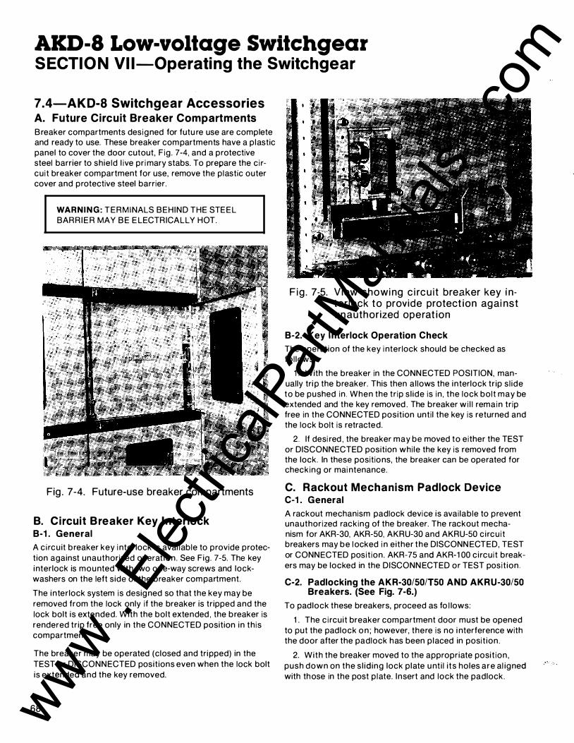
AKD-8 Low-voltage Switchgear S ECTIO N VI I-Operating the Switchgear
7.4-AKD-8 Switchgear Accessories A. Future Circuit Breaker Compartments Breaker compartments designed for futu re use are complete and ready to use. These breaker compartments have a p lastic panel to cover the door cutout, F ig . 7-4, and a protective steel barrier to shie ld l ive pr i mary stabs. To prepare the c i rcu i t breaker compartment for use, remove the plastic outer cover and protective steel barrier.
WARNI N G : TERMINALS BEHIND THE STEEL BARR IER MAY BE E LECTRICALLY HOT.
Fig . 7-4. Future-use breaker compartments
B. C i rcuit B reaker Key I nterlock B-1 . General
A c i rcu it breaker key i nterlock is avai lable to provide protection against unauthorized operat ion. See Fig. 7-5. The key interlock is mounted with two one-way screws and lockwashers on the left side of the breaker compartment.
The interlock system is designed so that the key may be removed from the lock only if the breaker is tripped and the lock bolt is extended. With the bolt extended , the breaker is rendered tr ip free only in the CONNECTED position in th is compartment.
The breaker may be operated (closed and tripped) in the TEST or DISCONNECTED posit ions even when the lock bolt is extended and the key removed.
68
F ig . 7-5. V iew showi ng c i rc u it breaker key i nter lock to provide protect ion agai nst unauthor ized operat ion
B-2. Key Interlock Operation Check
The operation of the key i nterlock should be checked as fol lows:
1 . With the breaker in the CONN ECTED POSITION, manually tri p the breaker. This then al lows the interlock tr ip s l ide to be pushed in . When the tr ip s l ide is in , the lock bolt may be extended and the key removed . The breaker w i l l rema in tr ip free in the CONNECTED posit ion unti l the key is returned and the lock bolt is retracted.
2. If desi red , the breaker may be moved to either the TEST or DISCONNECTED position whi le the key is removed from the lock. In these positions, the breaker can be operated for checking or mai ntenance.
C. Rackout Mechanism Padlock Device C-1 . General
A rackout mechanism padlock device is avai lable to prevent unauthorized rack ing of the breaker. The rackout mechanism for AKR-30, AKR-50, AKRU-30 and AKRU-50 c i rcu i t breakers may be locked i n either the DISCONN ECTED, TEST or CONNECTED posit ion. AKR-75 and AKR-1 00 c i rcu i t breakers may be locked in the DISCONN ECTED or TEST posit ion .
C-2. Padlocking the AKR-30/50/150 AND AKRU-30/50 Breakers. (See Fig. 7-6.)
To padlock these breakers, proceed as fo l lows:
1 . The c i rcuit breaker compartment door must be opened to put the padlock on ; however, there is no i nterference with the door after the padlock has been p laced in posit ion.
2. With the breaker moved to the appropriate posit ion, push down on the s l id ing lock p late unt i l i ts holes are al igned with those in the post p late. Insert and lock the padlock.
www . El
ectric
alPar
tMan
uals
. com

SECTION VI I-Operating the Switchgear
F ig . 7-6. Rack ing mechan ism pad lock device (AKR-30/50/T50 and AKRU-30/50 breakers)
C-3. Padlocking the AKR-75/1 00 Breakers. (See Fig. 7-7.)
1 . The circuit breaker compartment door must be opened to put the pad lock on ; however, there is no i nterference with the door after the padlock has been p laced in posit ion.
2. The pad lock device wi l l permit locking the crad le i n the DISCONN ECTED or TEST posit ion . Hasps, which pivot on the corner post in combi nat ion with the c i rcu i t breaker crank i nterlock, prevent movement of the breaker from its locked position.
3. Al ign the appropriate hasp (front hasp for DISCONNECTED posit ion or rear hasp for TEST posit ion) , i nsert, and lock the pad lock.
D. I nstal l ing and Removing M ete ring Cu rrent Transformers
WARNING : DO NOT OPERATE ANY CURRENT TRANSFORMER WITH SECONDARIES OPENCIRCUITED. BE SURE TO SHORT CIRCUIT SECONDARY BEFORE MOVING A CURRENT TRANSFORMER.
Fig. 7-7 . Rac k i ng mechan ism pad lock device (AKR-75/1 00 breakers)
Cu rrent transformers (CT's) for meteri ng are general ly mounted on the stationary pri mary d isconnect studs in the breaker compartment and are read i ly accessible for i nspect ion and replacement. In some appl ications they are located in the bus compartment or in the transition sect ion .
When cu rrent transformers are mou nted i n device compartments, care must be exercised when instal l i ng or removi ng transformer mount ing screws so as not to str ip the holes in the p lastic base. Do not torque screws over n ine ft/ lbs.
E. Removing Sh utter U n its Visual i nspection of pr i mary d isconnects and CT's can be made by f i rst removing the breaker and open ing the shutters manual ly . Th is is done by pressing the left and r ight hand actuat ing rol lers toward the rear of the compartment s imu ltaneously. This is a two-hand operation.
I f i t is necessary to perform work on the pri mary d isconnects or CT's, i t is necessary to remove the ent ire shutter un it .
69 www . El
ectric
alPar
tMan
uals
. com

AKD-8 Low-voltage Switchgear S ECTIO N VI I-Operating the Switchgear
70
WARNI NG : UN LESS THE PROPER PRECAUTIONS ARE TAKEN, THE REMOVAL OF A SHUTTER UNIT PRESENTS THE HAZARD OF E LECTRICAL SHOCK AND BURN.
DO NOT REMOVE THE SHUTTER UNIT UNLESS THE EQUI PM ENT HAS BEEN DE-ENERGIZED.
FAI LURE TO DO THIS CAN RESULT IN SERIOUS INJU RY.
0 0
1 . Frame assembly 2. Frame assembly 3. Shutter Actuator
r-- - - - - -1 I I
7. 8. 9.
Support block Support block Bottom shield
E-1 . Removing an AKR-30/50 or AKRU-30/50 Shutter Unit
To remove these sh utter un its, proceed as fo l lows :
1 . The sh utter unit frame is mounted on the vertical st r ingers located at each side of the rear of the breaker compartment. See F ig . 7-8.
2. Take out two %-i nch hex head screws on each side of the frame. A socket wrench with a 7/winch dr iv ing head with 4-inch extension will be needed .
1 3. Screw 1 4 . R ing 1 5. Spring
4. Bottom shutter 1 0. Connector l ink 1 6. Complete upper shield assembly 5. Top shield 1 1 . Spring 1 7. Shield cover 6. Center shield 1 2 . Spring 1 8. Label
Fig. 7-8. AKD-8 c ircuit breaker shutter un i t (AKR-30/50 breakers)
www . El
ectric
alPar
tMan
uals
. com

SECTION VI I-Operating the Switchgear
D I
1 . Side frame assembly (right) 2. Side frame assembly (left) 3. Movable shield assembly
4. Front shield 5. Shutters 6. Shutter actuator
Fig . 7-9. AKD-8 c i rc u it breaker sh utter u n it (AKR-75/1 00 breakers)
3. Careful ly remove the ent ire sh utter frame. It is necessary to t ip the bottom of the frame sl ightly forward to d isengage the f lange at the top of the frame from the vertical sh ie ld across the top of the rear compartment wal l .
4 . The frame is then maneuvered forward past the cam plates on each side, then upward and forward over the cam p i ns.
E-2. Removing an AKR-75/1 00 or Fuse Roll Out Shutter Unit
To remove these shutter un its, proceed as fo l lows.
1 . Fi rst, withdraw the d rawout undercarriage. The shutter un i t frame is mou nted to the vertical stringers located at each side of the rear of the breaker compartment.
2. Take out fou r %-i nch hex head screws on each side of the frame. A socket wrench with a 7/1 s- inch dr iving head with 8- i nch extension wi l l be needed . See Fig. 7-9.
3. Carefu l ly remove the ent ire sh utter frame, l i fti ng it s l ightly to clear the rol lout undercarriage.
NOTE : I f the compartment contains a position switch (Fig. 7-1 0), i t must be moved sl ightly to al low the frame to be taken out. To do this, remove two %-inch hex head screws which hold the posit ion switch mounting bracket to the right stri nger of the compartment. It is not necessary to d isconnect the wiring. The switch and its bracket can be moved enough to clear the shutter frame as it is removed .
71 www . El
ectric
alPar
tMan
uals
. com

AKD-8 Low-voltage Switchgear SECTIO N V I I-Operating the Switchgear
ST R I N G E R ( R I G H T S I D E)
n I
' I LJ TOP F R A M E O F B R E A K E R
- -'I
ROLLER C A M
I ASSEM B LY
_ _ � / I N EQU I PM E NT BACK OF ______,(__ B R EAKER I
-��ROLLER
, I , it---� Ll--�-- == �---- =-�
'· __) ��
F ig . 7-1 0. Pos i t ion switch assembly (AKR-75/1 00 breakers)
F. I nstal l ing a Sh utter U n it F-1 . I nstal l ing an AKR-30/50 or AKRU-30/50 Shutter Unit
72
WARNING: UN LESS THE PROPER PRECAUTIONS ARE TAKEN, THE INSTALLATION OF A SHUTTER U N IT PRESENTS THE HAZARD OF ELECTRICAL SHOCK AND BURN.
DO NOT INSTALL THE SHUTTER UNIT U NLESS THE EQUIPMENT HAS BEEN DE-ENERGIZED.
FAI LURE TO DO THIS CAN RES U LT IN SERIOUS INJURY.
To i nstal l these sh utter un its, proceed as fol lows :
1 . Carefu l ly maneuver the sh utter frame i nto the compartment, fi rst l ifti ng it over the cam p ins on each side wal l and past the cam plates.
2. Tip the upper edge back so it w i l l sl i p up behind the vert ical shield at the top rear of the compartment.
3. Position the rear flanges of the sh utter frame agai nst the vertical str ingers at the rear corners of the compartment.
www . El
ectric
alPar
tMan
uals
. com

SECTION VI I-Operating the Switchgear
4 . Al ign t h e ho les i n the flange and dr ive in two %-inch hex head screws us ing a 7/16- inch driver with a socket wrench with a 4-i nch extension.
5. Check the operat ion of the moveable shutters by pressing the left and r ight hand actuating rol lers toward the rear of the compartment.
F-2. Installing an AKR-75/1 00 Fuse Roll Out Shutter Unit
To instal l these shutter un its, proceed as fo l lows:
1 . F i rst, withdraw the drawout undercarriage.
2. Carefu l ly maneuver the sh utter frame i nto the compartment, l i fti ng it s l ight ly to clear the ro l l out undercarriage.
3. Posit ion the rear flanges of the shutter frame agai nst the vertical stri ngers at the rear corners of the compartment.
4. A l ign the ho les in the flange and drive in fou r %-i nch hex head screws using a 7/1 6- inch driver with a socket wrench with 8- inch extension.
5. Check the operation of the moveable sh utters by pressing the left and r ight hand actuat ing rol lers toward the rear of the compartment.
SECTION VI I I-Energizing the Switchgear
8.1 - Before Energizi ng Before switchgear is energ ized, a thorough f i nal check should be made us ing the fol lowing check l ist :
• Breakers and other operating mechanisms exercised
• Electrical insu lat ion resistance tested phase-to-phase and phase-to-g round
• Relays, meters and instru ments properly connected
• Electrical ly operated breakers and operating mecha-n isms exercised
• Ground fau lt protection system tested
• Adj ustable tr ips properly set
• Field wir ing secu red and free of l ive bus
• Ground i ng con nections made
• Al l debris, scrap wire, etc. removed
• Al l covers i nstal led , doors c losed and latched
8.2-Energizi ng
CAUTI O N : ENERGIZING SWITCHGEAR FOR THE FI RST TI M E IS POTENTIALLY DANGEROUS. THEREFORE, QUALI F IED ELECTRICAL PERSONN EL SHOU LD BE PRESENT WHEN THE EQU IPMENT IS ENERGIZED. I F PROBLEMS CAUSED BY DAMAGE OR POOR INSTALLATION PRACTICES HAVE NOT BEEN DETECTED IN THE CHECKOUT PROCEDURE DESCRI BED PREVIOUSLY, SERIOUS DAMAG E CAN RESULT WHEN POWER IS TURNED ON.
A. En ergizing Proced u res 1 . There should be no load on the switchgear when it is
energized .
2. Turn off al l of the downstream loads, i nc lud ing those such as motor control centers and other devices which are remote from the switchgear.
3. The equ ipment should be energ ized in sequence by start ing at the source end of the system and working toward the load end. In other words, energ ize the main devices, then the feeder devices, and then the branch-c i rcuit devices.
4. Turn the devices on with a f irm positive mot ion.
73 www . El
ectric
alPar
tMan
uals
. com

AKD-8 Low-voltage Switchgear SECTIO N IX-Maintain ing the Switchgear
9.1 - M a i nten ance Requ irements A. G eneral A periodic maintenance schedu le must be establ ished to obtain the best service from the switchgear. An annual check should be made and over-al l mai ntenance procedures for the switchgear devices and al l connections should be fol lowed as a m in imum requ i rement. Equipment subject to h igh ly repetitive operation may requ i re more frequent maintenance.
A permanent record of all mai ntenance work should be kept. The record should inc lude a l ist of periodic checks and tests made, the date they were made, the condition of the equ ipment, and any repairs o r adjustments that were performed . Maintenance employees must follow al l recog nized safety p ractices, such as those contained in the National Electric Safety Code ANSI C2-1 981 and in company or other safety regu lat ions during the mai ntenance.
WARNING: SOLID INSULATION SUR ROUNDING AN EN ERGIZED CONDUCTOR AND POWER APPARATUS MUST NEVER BE RELIED UPON TO PROVIDE PROTECTION TO PERSONNEL .
For specific information regard ing the mai ntenance of devices, such as c i rcu it breakers, relays, meters, etc . , refer to the separate i nst ruction book fu rnished for each device.
9.2- Breaker a nd I nstrument Compartme nts
Periodic i nspection of the c i rcu it breaker is recommended at least once a year . More f requent i nspections are recommended where severe load condit ions, dust, moistu re or other u nfavorable condit ions exist, or if the vital nature of the load warrants it .
Always i nspect the breaker after a short-ci rcu it cu rrent has been interrupted .
A. B reakers A-1 . Test for Proper Operation
Test and inspect all c ircuit breakers for proper operation as fol lows :
1 . Operate each breaker whi le i n the TEST position and check al l fu nctions. This is part icu larly important for breakers that normal ly remain in either the opened or closed positions for long periods of time.
. 74
WARNING: PRIMARY EQUIPM ENT MUST BE COMPLETELY DE-ENERGIZED WH ILE TESTS ON CONTROL CIRCUITS, ETC. ARE BEING CONDUCTED. BE SURE THAT ALL AREAS OF FEEDBACK FROM SECONDARY CIRCUITS, AS WELL AS OUTSIDE SOURCES, ARE DISCONNECTED .
2. Remove the breakers from their compartments to a clean maintenance area. Close the compartment door and cover the breaker cutout to prevent access to l ive parts.
WARNING: DE-ENERG IZE EQU I PMENT COMPLETELY BEFORE DOING MAINTENANCE WORK ON ANY DEVICES, CONNECTIONS, BUS WORK, BREAKER OR FEEDER CABLE COMPARTM ENTS. THIS I NCLUDES DE-EN ERGIZING ANY CONN ECTIONS TO OUTSIDE PRI MARY OR SECONDARY SOURCES, SUCH AS TRANSFORMERS, TIE L INES, ETC.
A-2. Checks After Breaker Is De-energized
At the time of inspection , the fo l lowing checks should be made after the breaker has been de-energ ized .
1 . Manual ly operate the breaker several t i mes, checking for obstructions or excessive frict ion. Man ual closi ng of an electrical ly operated breaker may be performed by the fo l lowi ng two steps:
a. i nstal l maintenance crank (568B386G 1 ) to the motor gear reducer shaft on the front right side of the breaker. Ratchet the mai ntenance crank up and down unt i l the springs are fu l ly charged as ind icated by the d istinct c l ick as the prop is set which prevents any further charg ing of the closing springs. After the prop is set, do not apply undue force to the mai ntenance handle.
b. On AKR-75 and AKR-1 00 breakers depress the SPRING DISCHARGE lever located under the horizontal support on the front frame. The springs should d ischarge and , if the latch is properly reset, the breaker wi l l c lose.
2. E lectrical ly operate the breaker several times to check performance of the electrical accessories.
3. Visual ly check the b reaker for loose hardware on the breaker ; also, check the bottom of the compartment for any hardware that has fal len from the breaker.
4. Remove the arc quenchers and inspect the arc quenchers and contacts for breakage or excessive burn ing .
5. The performance of the solid-state current tr ip devices may be checked with a su itable test set. Check electromechan ical devices for positive trip in accordance with the instructions in the proper Maintenance Manual .
6. Check insu lating parts for evidence of overheat ing and for cracks that ind icate excessive thermal ag ing .
Refer to c i rcuit breaker i nstruction manuals for detai led mai ntenance instructions and information for rep lacement of parts.
www . El
ectric
alPar
tMan
uals
. com

SECTION IX-Maintain ing the Switchgear
A-3. Lubrication
In general, the circuit breaker requi res moderate lubrication. Bearing points and sliding surfaces should be lubricated at the regular inspection periods with a thin film of G E lubricant 0282A2048P009. Before lubricating, remove any hardened grease and dirt from latch and bearing surfaces with kerosene.
CAUTION : ALL EXCESS LUBRICANT SHOULD BE REMOVED WITH A CLEAN CLOTH TO AVOID ACCUMU LATION OF D IRT OR DUST.
On drawout breakers, the contact surface of the disconnectt fingers should be cleaned and greased with G E lubricant 0282A2048P009.
B. I n struments, I nstrument Tra nsformers, and Relays
Check and i nspect al l devices to see that they are functioning properly. Check that al l electrical connections are t ight . Check mou nti ng of the device.
Under normal cond it ions, the protective relays do not operate; therefore, it is important to check the operation of these devices regu larly. Refer to Relay I nstruction Books for detai led i nstructions.
C. B reaker Compartment I nteriors
WARNING: DE-ENERGIZE EQUIPM ENT COMPLETELY BEFORE DOING MAINTENANCE WORK IN COMPARTM ENTS. TH IS INCLUDES DE-EN ERGIZING ANY CONNECTIONS TO OUTSIDE PRI MARY OR SECONDARY SOURCES, SUCH AS TRANSFORM ERS, TIE LINES, ETC.
1 . Thoroughly clean the i nterior of the breaker and instrument compartments. Use a vacuum cleaner and clean rags only. Do not use steel wool or oxide papers. B lowing with compressed air i s not recommended .
2. Check ind icati ng devices, mechanical and key interlocks.
3. Check pri mary d isconnect ing device contacts for signs of abnormal wear or overheati ng. Discoloration of the si l vered surfaces is not ord i nari ly harmfu l . These contacts should be cleaned on ly by wip ing with a l i nt-free cloth.
4. Clean the racking mechanism and lubricate with GE lubricant 0282A2048P009.
5. Before replacing the breaker, wipe off the primary and secondary disconnecting device contacts. Apply a thin coat of G E lubricant 0282A2048P009 to the stationary studs and to the primary and secondary disconnects on the breaker.
9.3-Bus Area I nspect and check the bus area as fol l ows :
1 . I nspect the buses and connections carefu l ly for evidence of overheat ing or weaken ing of the insu lati ng supports.
a. If bus i nsu lation is present, remove the molded covers over the main bus connection to expose jo ints for i nspect ion .
2. Check al l connection bolts i n the bus compartment and al l braci ng bo lts for t ightness. See the Torque Table A-1 in Appendix A.
3. Vacuum and, with a clean rag , wipe the buses and supports.
4. Visual ly inspect the i nsulation on the bars that run from the breaker studs through the bus structure to the cable area.
5. After clean ing , megger and record the resistance to ground and between phases of a l l i nsulated bars and al l buses and connections. D isconnect al l control c ircu its before check ing resistance. Do not use over a 1 500-volt megger. Si nce def in ite l im its cannot be g iven for satisfactory insu lat ion resistance val ues, a record must be kept of the read i ngs.
Weaken ing of the i nsulation from one mai ntenance period to the next can be recogn ized from the recorded readi ngs. The read i ngs should be taken u nder s imi lar condit ions each time, if possi ble, and the record should i nclude the ambient temperature and hum id ity.
9.4-Cable and Busway Com partment
I nspect and check the cable and busway compartment as fol lows:
1 . I nspect all power cable con nections for signs of overheat ing and t ighten al l connections. If severe d iscoloration or if damage is apparent, remove the damaged portion of the cable.
CAUTION: BE SURE THE CONDITION WHICH CAUSED THE OVERHEATING HAS BEEN CORRECTED BEFORE ENERGIZING.
2. Check al l bolts that hold cable termi nals to the connect ion bars for t ightness.
3. Check the neutral bus and ground bus connection and mounting bolts for t ightness.
4. Check that a l l secondary control wir ing connections are t ight and that a l l control cab l ing is i ntact.
75 www . El
ectric
alPar
tMan
uals
. com

AKD-8 Low-voltage Switchgear SECTIO N IX-Maintain ing the Switchgear
9.5-0ve r-al l Switchgear Make the fol lowing checks on the complete switchgear equipment.
1 . Clean and inspect al l painted su rfaces and retouch where necessary.
2. Check to see that a l l anchor bolts and other structural bolts are t ight.
3. Check that a l l breaker and i nstrument compartment door latches operate properly.
4. If the switchgear is eq u ipped with heaters, check to see that a l l heaters are energ ized and operat ing .
5. For exter ior vent openi ngs in equ i pment furn ished with air f i lters, the foam f i l ter elements should be removed and washed in warm soapy water, ri nsed , and reassembled at least annual ly. Elements should be i nspected before reassembly and replaced if any signs of deteriorat ion are evident.
9.6- Paint Refi n is h i n g Indoor switchgear i s finished with ANSI-61 gray acrylic enamel paint GE part number 0282A4534P001 . To refinish damaged areas, remove all loose paint, rust, scale, oil or grease. Sand any scratches smooth .
1 . Refinishing with Acrylic Enamel (Standard ANSI-61 gray finish)
-Apply a coat of good acryl ic enamel primer-sealer (0282A4534P005). Air dry the primer for Y2 hour, then apply the finish color coat of acrylic enamel.
- If the area is to be spray-coated, thin the acrylic enamel with 0282A4534P006 (this thinning is only necessary if the paint was received in a five gallon drum). Use one part thinner to four parts enamel as a starting point to obtain the correct spraying viscosity. When paint is received in less than five gallon quantities the paint has been factory-thinned. Both the primer and paint should be applied only when the temperature is above 55 degrees fahrenheit.
76
2. Refinishing with Acrylic Lacquer (Special colors by request of purchaser)
-Apply a coat of good acrylic lacquer primer-sealer (GE number 0282A4534P005) . A i r dry the primer for V2 hour, then apply the finish color coat of acryl ic lacquer.
- If the area is to be spray-coated, thin the acrylic lacquer with a blush resistant thinner (02824534P007) (this thinning is only necessary if the paint was received in a five gal lon drum). Use one part thinner to one part lacquer as a starting point to obtain the correct spraying viscosity. When paint is received in less than five gallon quantities, the paint has been factorythinned. Both the primer and paint should be applied only when the temperature is above 55 degrees fahrenheit.
9. 7-Circuit Bre a ker Lifting M ech anism
Under normal condit ions, no special mai ntenance procedures or lubricat ion is requ i red for this device. If the cable is abraided under any cond it ion , it should be i nspected for broken strands or other damage and replaced i f necessary.
www . El
ectric
alPar
tMan
uals
. com

APPEN DIX A-Torque Values
Table A-1 -Torque Val ues for Lowvoltage Equipment Electrical Joint H ardware other than Cable Terminals (Copper or Al uminum)
Hardware Size
%-20 %-1 6 %-1 3 %-1 1
Torque* (Wibs)
Standard Nut with Conical Spring Washer
or Lockwasher
7-9 25-30 35-40 45-55
·rhese torque values are for non-lubricated threads
Table A-2-Torq ue Val ues for Selfthreading Screws in Plastic
Caution should be exercised when instal l i ng parts or components to the compartment molded base. Torque V.-inch screws slowly and do not exceed n ine ft/ lbs.
Table A-3-Torq u e Val ues for Cable Termi nals
Wire Torque* Size (H-Ibs)
6 I 5 8 4 3
3 } 1 0 2 1
0 } 12 00
000 } 1 7 0000 200,000
250,000 1 21 300,000 350,000 400,000
500,000 ) 25 600,000 700,000 750,000
800,000 } 33 900,000 1 ,000,000
1 ,250,000 ) 42 1 ,500,000 1 ,750,000 2,000,000
·rhese torque values are for non-lubricated th reads.
APPENDIX B-Circuit Breaker Rejection Features
8.1 -General In general , d rawout breakers of the same type and rating are interchangeable in thei r eq u ipment compartments; d rawout breakers of d i fferent frame sizes or short c i rcuit ratings are intentional ly made non-interchangeable. To prevent inserting the wrong type breaker into a drawout compartment, un ique " rejection hardware" is affixed to each breaker and its compartment. Two different mountings of rejection hardware used: one for those breakers mou nted in 22-inch wide compartments (AKR-30/50 fam i ly) and the other for those breakers mou nted in 30-i nch wide compartments (AKR-75/ 1 00 fami ly) . The d ifferent types of rejection hardware are requ i red due to different d rawout mechanisms used for the two breaker fami l ies.
Fig. 8-1 . Breaker-mounted rejection bracket
77 www . El
ectric
alPar
tMan
uals
. com

AKD-8 Low-voltage Switchgear APPEN DIX B-Circuit Breaker Rejection Featu res
B-1 A. 22-l nch Wide Compartment Figu re B-1 (AKR-30/50 breaker fami ly) shows the breakermounted rejection bracket and its un iquely located slot.
This s lot (one in each side of the breaker) must a l ign with a rejection p in un iquely located on the d rawout rai l , one on each rai l .
When the wrong type breaker is inserted i nto a compartment, the bracket and pin do not mate, preventing the breaker from seat ing itself i nto the rai l slots.
There is one exception to the above rule. Breakers of the same frame size, hav ing d i fferent short c i rcu it rat ings, may be i nterchanged in one d i rection only. Specif ical ly :
78
1 . An AKR-30H can be i nserted i ntq an AKR-30 compartment.
2. An AKR-50H can be i nserted i nto an AKR-50 compartment.
The reject ion hardware prevents the converse of 1 . and 2.
Figure B-2 shows the the rejection pin/bracket combinations employed for the various breaker models and frame sizes. As dictated by its intended breaker type, each drawout compartment has its rejection pin(s) installed in positions A, B or C (Fig. B-2) along the drawout rai ls . The AKRU-30/50 fused breakers employ a single bracket while all non-fused breakers employ two brackets.
www . El
ectric
alPar
tMan
uals
. com
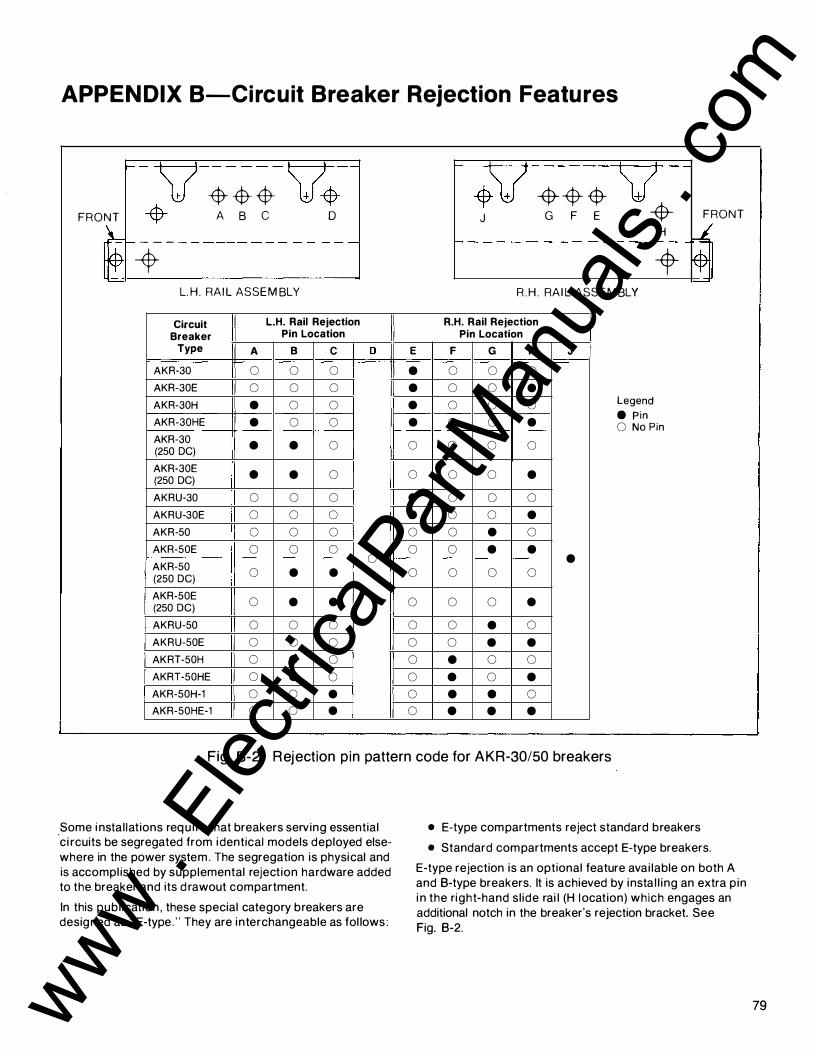
APPEN DIX B-Circuit Breaker Rejection Features
�
FRONT
.v � � $- v� -$- A B C 0
· -
��c-_.-- ------ - - - - - - --
L. H. RA I L ASSEMBLY
Circuit L.H. Rail Rejection
Breaker Pin Location
Type A B c
AKR-30 0 0 0
AKR-30E 0 0 0
AKR-30H • 0 0
AKR-30HE • 0 0
AKR-30 • • 0 (250 DC)
AKR-30E • • 0 (250 DC)
AKRU-30 0 0 0
AKRU-30E 0 0 0
AKR-50 0 0 0
AKR-50E 0 0 0
AKR-50 (250 DC)
0 • •
AKR-50E 0 • • (250 DC)
AKRU-50 0 0 0
AKRU-50E 0 0 0
AKRT-50H 0 • 0
AKRT-50HE 0 • 0
AKR-50H-1 0 0 • AKR-50HE-1 0 0 •
D E • • • •
0
0
• • 0
0 0
0
0
0
0
0
0
0
0
-
�v -$--$- {$- v J G F E -$-
H
-
- - - - - - - - - - - - - - - - -
-t R.H . RA I L ASSEMBLY
R.H. Rail Rejection Pin Location
F G H J
0 0 0
0 0 • 0 0 0 Legend
0 0 • e Pin 0 No Pin
0 0 0
0 0 •
0 0 0
0 0 • 0 • 0
0 • • •
0 0 0
0 0 •
0 • 0
0 • • • 0 0
• 0 • • • 0
• • •
FRONT
LL �
Fig. 8-2. Rejection p in pattern code for AKR-30/50 breakers
.some i nstal lations requ i re that breakers serving essential ci rcuits be segregated from identical models deployed elsewhere in the power system . The segregation is physical and is accompl ished by supplemental rejection hardware added to the breaker and its d rawout compartment.
In this publ ication , these special category breakers are designed as "E-type. " They are interchangeable as fol lows :
• E-type compartments reject standard breakers
• Standard compartments accept E-type breakers.
E-type rejection is an optional feature avai lable on both A and B-type breakers. It is achieved by insta l l ing an extra p in i n the right-hand sl ide rai l (H location) which engages an additional notch in the breaker's rejection bracket. See Fig. B-2.
79 www . El
ectric
alPar
tMan
uals
. com

AKD-8 Low-voltage Switchgear APPEN DIX 8-Circuit Breaker Rejection Features
B-1 B. 30- lnch Wide Compartment Like the AKR-30/50 breaker fami ly , AKR-75/1 00 breakers for AKD-8 switchgear height and width also must inc lude means to prevent inadvertent i nterchange of these 3200- and 4000-
ampere sizes. This is done by adding interference hardware to each breaker and its compartment, causing the compartment to accept the correct breaker type and reject al l others.
E -- +
-$-A -f-----$ + c
B -f---• • D
-$-+ + I J
I l + I � I
\.. ) L. H . TRAY ASSEMBLY
However, due to the d ifference in drawout mechanisms, the hardware to provide the rejection featu res d iffers from that for AKR-30/50 breakers.
Interchangeability within and between frame sizes is prevented by the rejection system of Fig. B-4 Variously positioned pins on the drawout tray must align with matching
�
• K
-$-F + + H
G -t • J
--$-) : + \ I +
I + \ R.H . TRAY ASSEMBLY
Circuit CB L.H. Tray Rejection Pin R.H. Tray Rejection Pin
Breaker Location Location
Type Volts
A B c D E F G H J K
250Vdc 0 • 0 • 0 " • 0 • 0 \J
AKR-75 500Vdc 0 • • 0 0 0 • 0 • 0 600Vac 0 • • 0 0 • 0 0 • 0 Legend
250Vdc 0 • 0 • • 0 • 0 • • e Pin
AKR-75E 500Vdc 0 • • 0 • 0 • 0 • 0 No Pin
• 600Vac 0 • • 0 • • 0 0 • • 250Vdc • 0 • 0 0 • 0 • 0 0
AKR-1 00 500Vdc • 0 0 • 0 • 0 • 0 0 600Vac • 0 0 • 0 0 • • 0 0 250Vdc • 0 • 0 • • 0 • 0 •
AKR-1 00E 500Vdc • 0 0 • • • 0 • 0 • 600Vac • 0 0 • • 0 • • 0 •
Fuse Rol lout 600Vac • 0 0 • 0 0 0 0 • 0 3200A
Fuse Rol lout 600Vac • 0 0 • • 0 0 0 • •
3200A " E "
Fuse Rol lout 600Vac 0 • • 0 0 0 0 0 • 0
4000A
Fuse Rol lout 600Vac 0 • • 0 • 0 0 0 • •
4000A " E "
Fig . B-3 . Rejection pin pattern code for AKR-75/1 00 breakers and FRO
80 www . El
ectric
alPar
tMan
uals
. com

APPEN DIX B-Circuit Breaker Rejection Features
holes and notches i n rejection plates bolted to the breaker's bottom flanges. An i ncorrect style breaker presents a mismatch and wi l l not seat on the tray. Figure B-5 shows the location of the rejection pins on the d rawout tray.
E-type reject ion, as previously descri bed for AKR-30/50 breakers, is ach ieved by notching the breaker's r ight side plate to clear a special rejection p in added to the right sl ide rai l .
B-2. Fuse Rollout Elements Fuse rol lout (FRO) elements to be used in conj unction with either the AKR-75 (3200 ampere) or AKR-1 00 (4000 ampere) breakers employ the same type d rawout mechan ism as its companion breaker and uti l ize the same type rejection system. Only a 3200-ampere fuse ro l lout element may be i nstal led i n a 3200-ampere fuse rol lout compartment ; l i kewise on ly a 4000-ampere fuse ro l lout element may be instal led in a 4000-ampere fuse rol lout compartment. The rejection pin pattern is shown on Fig. 8-3.
Fig. B-4. View showing location of rejection pins on drawout tray
APPEN DIX C-Circuit Breaker Ratings
Table C-1 -General Circuit Breaker Ratings
Frame System Three-phase Short Circuit Rating RMS Symmetrical kA
Breaker Nominal With Without Size Type Voltage Short-
Instantaneous Instantaneous (Amperes) 60 Hz, Ac Time Trip Trip
600 22 22 -800 AKR-30S 480 22 30 -
240 22 42 -600 30 30 30
800 AKR-30 480 30 30 30 240 30 42 30
600 42 42 42 800 AKR-30H 480 42 42 42
240 42 50 42
600 42 42 42 1600 AKR-50 480 50 50 50
240 50 65 50
600 65 65 65 1600 AKR-50H-1 480 65 65 65
240 65 65 65
600 65 65 65 2000 AKRT-50H 480 65 65 65
240 65 65 50
3000} 600 65 65 65 AKR-75 480 65 65 65
3200 240 65 85 65
3000} 600 85 85 85 AKR-75H 480 85 85 85
3200 240 85 130 85
600 85 85 85 4000 AKR-100 480 85 85 85
240 85 130 85 8 1 www .
Elec
tricalP
artM
anua
ls . c
om

AKD-8 Low-voltage Switchgear APPEN DIX C-Circuit Breaker Ratings
Table C-2 - lntegral ly Fused Circuit Breaker Ratings
Rated CLF Fuse Interrupting Frame
Breaker Maximum Rating Rating Size
(Amperes) Type Voltage (Amperes) RMS
60 Hz, ac Min Max Symmetrical kA
800 AKRU-30S 600 300 1600 200 800 AKRU-30 600 300 1600 200
1600 AKRU-50 600 450 2500 200
Table C-3-Circuit Breaker Control-operating Curre nts
Rated Voltage Amperes Inrush/Sustained
Mode Voltage Range AKR-30/50
AKR-75/1 00 AKRT-50
Closing Ae r20 1 04-1 27 25/5 25/8. 1
60 Hz 240 208-254 1 2/3 1 2/3.5
De r 25 1 00-1 40 27/5 27/7 250 200-280 1 3/3 1 3/3.2
Tripping Ae { 1 20 95- 1 27 1 2.3/1 0.8
60 Hz 240 1 90-254 3.9/3.4
De r 25 70-1 40 1 .9/1 .9 250 1 40-280 1 .0/1 .0
APPEN DIX D-Circuit Breaker Accessory Device Ratings
S h u nt Trip The shunt tr ip offers remote electrical tripping of breakers. Usua l ly contro l led by a switch or push button, it may also be used in conjunction with protective relays for automatic tripp ing .
The shunt tr ip coi l is rated for intermittent duty. When ordered factory instal led, it is suppl ied with a cutoff switch which automatical ly removes control power fol lowing a breaker tr ip . See Table D-1 .
Table D-1 Control Voltage Shunt Trip Amperes
Nominal Operating
Inrush Sustained Range
48 28-60 4.5 4.5 , • De 125 70-140 1 .9 1 .9
250 140-280 1 .0 1 .0
120 95-127 12.3 10.8 208 175-220 3.2 2.6
60 Hz Ae 240 190-254 3.9 3.4
480 380-508 3.4 3.1 575 475-625 2.8 2.5
82
Undervoltage Trip (UV) The undervoltage tr ip device protects agai nst harmful drops in l i ne voltage by automatical ly tr ipping the breaker. This device is set to pick up at approximately 80 percent of bus voltage and d rop out between 30 percent and 60 percent. See Table D-2.
Table D-2
Control UV Coil Amperes
Voltage Inrush Sustained
48 0.20 0.20 De 125 0.07 0.07
250 0.04 0.04
120 0.66 0.24 60 Hz 208 0.51 0. 1 7
Ae 240 0.37 0 . 1 2 480 0.23 0.08
120 0.75 0.25 50 Hz 208 0.30 0. 1 0
Ae 240 0.34 0. 11 480 0.17 0.07
www . El
ectric
alPar
tMan
uals
. com

APPEN DIX D-Circuit Breaker Accessory Device Ratings
The U V device i s also avai lable with a n optional static t i medelay un it . Th is offers a field adjustable 2- to 6-second delay between undervoltage fau lt and breaker trip to prevent potential n u isance tripping due to momentary loss of voltage.
The ti me-delay u n it is mounted external to the breaker. It is rated 1 25 or 250 volts de or 208/240 volts ac, 50 or 60 hertz. For any other ac source voltage, a control power transformer with a 240-volt secondary rated at least 1 00 Va is requ i red .
Auxiliary Switc h The auxi l iary switch is used for remote ind ication of breaker mai n contact position and is avai lable in g roupi ngs of four contacts (two stages) or ten contacts (five stages). Each stage is composed of one "A"-Type (N.O.) contact and one " B"-Type (N.C.) contact. All contacts featu re rugged double break construction. See Tables D-3 and 4.
Table D-3
CB Auxiliary Switch Position
Main "A" "B" Contacts Contact Contact
Open (6 1 6 � or Open Closed
Tri pped ? ?
Closed � C losed � Open 16 ?
Table D-4 Auxiliary Switch
Control Interrupting Ratings
Voltage (Amperes)
Non-inductive Inductive
De 1 25 1 1 * 6.3* 250 2 1 .8
Ae 1 1 5 75* 50* 240 50* 25*
60 Hz 480 25* 1 2*
·um ited to 20 ampere conti nuous rating of switch on al l breakers and to 5-ampere cont inuous rating of No. 1 6 wire on drawout breakers.
Re mote Close Solenoid-For Manually Operated Type AKR-30/50 Breakers
This solenoid provides a means to electrically close the AKR-30/50 breakers from a remote locat ion. I t may be contro l led
by a switch or push button for five-cycle closing . The breaker must be charged local ly . The avai lable rat ings are shown i n Table D-5.
Table D-5
Control Amperes
Voltage Inrush Sustained
48 2.7 2.7 De 1 25 1 .3 1 .3
250 0.68 0.68
60 Hz 1 20 2.6 0.4 Ae 240 1 .3 0.2
Bell Al arm With Lockout The bel l alarm operates one "A" and one " B " contact or two A's or two B's. It is activated when the breaker is tri pped by any (automatic) means other than the manual tr ip button or the shunt tr ip device. The rat i ngs are shown in Table D-6.
The contacts may be used for remote ind ication of an automatic tr ip.
The lockout featu re is avai lable to mechan i cal ly lock the breaker " open" when the device is activated. " Reset" is accompl ished through operation of manual trip button or shunt tri p device.
The bel l alarm is avai lable without the lockout featu re when so specified.
Table D-6 Bell Alarm
Control Voltage Contact Ratings
(Amperes)
Inrush Continuous
De 1 25 2.5 2.5 250 0.9 0.9
60 Hz 1 1 5 30 1 0 230 1 5 5 Ae 460 7 3
Electric Lockout The electric lockout device provides a means of electrically i nterlocking breakers so that two cannot be closed at the same t ime. This electro-mechanical device consists of a coil whose winding m ust be energ ized to close the breaker. Once the breaker is closed , loss of voltage wi l l not tr ip the breaker. A bypass i nterlock is provided for in it ial start-up. Refer to the UV device for rat ings and coil characteristics.
Auxi l iary switches for cross-interlocking breakers must be ordered separately.
83 www . El
ectric
alPar
tMan
uals
. com

AKD-8 Low-voltage Switchgear APPENDIX E-Circuit Breaker Weights
Table E-1 - Average Weight (Pou nds)
Device Net Weight Shipping Weight
Manual Electrical Manual Electrical
AKR-30S 70 90 80 100 AKRU-30S 90 1 10 1 00 1 20
AKR-30 200 205 225 230 AKR-30H 200 205 225 230 AKRU-30 245 250 275 280
AKR-50 210 215 235 240 AKR-50H 210 215 235 240 AKRU-50 255 260 285 290
AKRT-50H 215 220 240 245
AKR-75 420 435 470 485
AKR-75H 420 435 470 485
AKR-100 525 560 575 590
2000-Ampere 250 300
Fuse Rollout
3200-Ampere 350 400
Fuse Rollout
4000-Ampere 400 450
Fuse Rollout
APPEN DIX F-Circuit Breaker Repetitive Duty Data
General Ci rcuit breakers are desig ned pr imar i ly to perform the funct ion of circuit i nterruption u nder short-c i rcuit conditions. Nevertheless modern c i rcu it breaker mechanisms are capable of many operat ions under fu l l-load operat ion and i n-rush
cond it ions such as encou ntered in motor starti ng appl ications. I ndustry standards have been estab l i shed fo r the m in i mum performance wh ich i s i nd icated i n Table F- 1 . With adequate mai ntenance, GE breakers can be expected to exceed the standards.
Table F-1 -Repetitive Duty and Normal M aintenance N u mber of
N u mber of Operations
Circuit Breaker Operations
Rated Continuous Frame Size
Between Current
(Amperes) Servicing
Switching* (A) (C) (D) (E)
(F) (G) (H) and (J)
225 2500 4000 800 1 750 2800
1 600 500 800
2000 500 800 3200 250 400 4000 250 400
•Refer to lettered paragraphs under NOTES.
Notes
Number of Operations
No-Load Closing and
Opening* (A) (B) (C) (D) (E) (F) and (G)
1 0000 9700 3200
3200 1 1 00 1 1 00
N umber of Operations
In-Rush Current
Switching* (C) (D) (E) (F) (G) (I) and (J)
2000 1 400
400
400 --
Power operated circuit breakers, when operati ng u nder usual service condit ions, shal l be capable of operating the n umber of ti mes specified in Table F-1 . The operat ing condi-
t ions and the permissible effect of such operat ions upon the breaker are g iven i n the fol lowi ng lettered paragraphs. For each col u m n , a l l paragraphs l isted i n the co l u m n head ing must be g iven considerat ion .
84 www . El
ectric
alPar
tMan
uals
. com

APPEN DIX F-Circuit Breaker Repetitive Duty Data
This standard appl ies to a l l parts of a circuit breaker that function during normal operation. It does not apply to other parts, such as overcurrent tr ipping devices, that function only du ring infrequent abnormal c i rcu it conditions. (H) (A) Servicing consists of adjusting , clean ing , l ubricat ing,
t ightening , etc. , as recommended by the manufacturer. When cu rrent is i nterrupted , d ressing of contacts may be requ i red as wel l . The operations l isted are on the basis of (I) servic ing at intervals of 6 moriths or less.
(B) When closi ng and opening no-load.
(C) With rated control voltage appl ied.
(D) Frequency of operation not to exceed 20 in 10 min utes or 30 in an hour. Rectifiers or other auxi l iary devices may further l i mit the frequency of operat ion.
(E) Servic ing at no g reater intervals than shown in Column 2 of Table F-1 .
c ircuit current. After completion of this series of operations, functional part replacement and general servic ing may be necessary.
When closing and opening current up to the continuous current rat ing of the c ircu it breaker at voltages up to the rated max imum voltage and at 85% of the power factor or h igher.
When closing cu rrents up to 600% and opening currents up to 1 00% (80% power factor or h igher) of the continuous cu rrent rating of the circuit breaker at voltages up to the rated maxi mum voltage.
When closing cu rrents up to 600% and open ing cu rrents up to 600% (50% power factor or less) of the continuous cu rrent rat ing of the circuit breaker at voltages up to rated maxi mum voltage, the nu mber of operations shown shal l be reduced to 1 0% of the number l isted .
(F) No fu nctional parts should have been replaced during the l isted operations.
(G) The c i rcu it breaker should be in a condition to carry its rated continuous cu rrent at rated maxi mum voltage and perform at least one opening operation at rated short-
(J) If a fau lt operation occurs before the completion of the l isted operations, servic ing is recommended and possible functional part replacements may be necessary, depending on previous accumulated duty, fau lt magnitude, and expected future operations.
APPEN DIX G-Fuses for AKRU-30/50 and FRO Elements
Table G-1 -Fuses for I ntegrally Fused AKRU Breakers
NEMA Breaker Type
Gould AKRU Ampere Fuse Class
Rating Shawmut
600V, 60 Hz 30/30S 50 Fuse Cat. No.
X - 3oo· A4J300 X - 35o• A4J350
"J" X - 4oo· A4J400 X X 450 A4J450 X X 500 A4J500 X X 600 A4J600 X X 800 A4BY800 X X 1 000 A4BY1 000BG "L" X X 1 200 A4BY1 200BG X X 1 600 A4BY1600BG - X 2000 A4BY2000BG
Special - X 2500 A4BX2500G E •Mounting adapter req u i red.
Table G-2-Fuses for Rol l-out Fuse Carriages
Fuse Fuse Size Fuse Cat. No's.
Carriage Min. Max. Gould Shawmut
3200 2000A 4000A A4BY2000 4000 2000A SOOOA A4BY3000
A4BY4000 A4BY5000
85 www . El
ectric
alPar
tMan
uals
. com

Notes
86 www . El
ectric
alPar
tMan
uals
. com

Notes
87 www . El
ectric
alPar
tMan
uals
. com

• GE Electrical Distribution & Control
General Electric Company 41 Woodford Ave., Plainville, CT 06062
GEH-5687 0191 BLA © 1991 General Electric Company
www . El
ectric
alPar
tMan
uals
. com