Embed Size (px)
Citation preview

Journal of Applied Research and Technology
ISSN: 1665-6423
Centro de Ciencias Aplicadas y Desarrollo
Tecnológico
México
Rodríguez-Reséndiz, J.; Gutiérrez-Villalobos, J. M.; Duarte-Correa, D.; Mendiola-Santibañez, J. D.;
Santillán-Méndez, I. M.
Design and Implementation of an Adjustable Speed Drive for Motion Control Applications
Journal of Applied Research and Technology, vol. 10, núm. 2, 2012, pp. 180-194
Centro de Ciencias Aplicadas y Desarrollo Tecnológico
Distrito Federal, México
Available in: http://www.redalyc.org/articulo.oa?id=47423215009
How to cite
Complete issue
More information about this article
Journal's homepage in redalyc.org
Scientific Information System
Network of Scientific Journals from Latin America, the Caribbean, Spain and Portugal
Non-profit academic project, developed under the open access initiative
Vol. 10 No.2, April 2012 180
Design and Implementation of an Adjustable Speed Drive for Motion Control Applications J. Rodríguez-Reséndiz*1, J. M. Gutiérrez-Villalobos1, D. Duarte-Correa1, J. D. Mendiola-Santibañez1, I. M. Santillán-Méndez1 1Universidad Autónoma de Querétaro, División de Estudios de Posgrado, Facultad de Ingeniería, Cerro de las Campanas s/n, 76010 Querétaro, México *[email protected] ABSTRACT In this article a hardware topology meant to compare the velocity performance of both an induction motor and a permanent magnet (PM) AC three-phase motor is presented. A variable reference is tracked by the sensorless vector-controlled adjustable speed drive (ASD) that permits, by means of the same type of control, performing the speed control loop of the two motors. The algorithms are programmed on a digital signal processor (DSP) in order to ensure efficient use of energy in the transistor bridge and proper tracking of the reference at low and high speeds. Regarding the torque performance, a laboratory test bed based on a torquemeter and two motors is constructed. The hardware implementation includes the power and the digital stages. A serial communication between the PC and the ASD is accomplished to put into operation in the user front-end because a high speed sample frequency is required for the analysis software that runs in the PC. This interface is used not only as comparing the speed response of the motors signals but also as looking the power quality analysis of each motor measurements based on software. Results are presented to demonstrate the effectiveness of the sensorless scheme. Keywords: Signal processing, vector control, AC motors, sensorless control, torque measurement. RESUMEN En este artículo se presenta una topología de hardware para comparar el rendimiento de velocidad de un motor de inducción y otro de imanes permanentes (PM) de AC. A una referencia variable le sigue un variador de velocidad ajustable (ASD) con base en control vectorial sin sensores. Los algoritmos se programan en un procesador digital de señales (DSP) para asegurar el uso eficiente de energía en el puente de transistores y el seguimiento de la referencia en velocidades bajas y altas. En lo que se refiere al rendimiento de torque, se construye una mesa de pruebas de laboratorio con base en torquímetro y dos motores. La implementación incluye la etapa de hardware y software. Se lleva a cabo una comunicación serial entre la computadora y el ASD para poner en operación una interfaz debido a la alta velocidad de muestreo que requiere por el análisis en software montado en una PC. Esta interfaz se utiliza no solo para la comparación de la respuesta de ambos motores sino también para observar el comportamiento de la propuesta del controlador en este trabajo. Se presentan resultados para demostrar la efectividad del esquema sin sensores.
1. Introduction Nowadays 3Φ induction and PM motors are utilized because they have excellent characteristics suitable for industry and home applications such as high efficiency, silent operation, compact form, simplicity, low cost, reliability and low maintenance. They can also frequently be found in pumps, conveyors, ventilating and air conditioning systems (HVAC), computer numerical controls (CNC), milling machines and robots. In the Mechatronics Laboratory at Universidad Autónoma de Querétaro, the research group is developing original controllers
aimed at driving both types of motors—induction motors are used for a milling machine and PM motors for a servo mechanism in robots. However, the control complexities of controlling speed and torque, and the high cost of the electric drive have been a drawback when using these types of motors [1], [2]. Thus, a complete experimentation when using these motors is carried out in this research. Most of the time motion control systems demand the use of sophisticated automation tools which

Design and Implementation of an Adjustable Speed Drive for Motion Control Applications, J. Rodríguez‐Reséndiz et al. / 180‐194
Journal of Applied Research and Technology 181
must have good performance. Features that should contain a commanded ASD are reliability, effectiveness in terms of power consumption, and cost-effectiveness, among others. These technologies frequently permit distributed control [3]. For instance, in sophisticated processes standard buses such as Modbus and Profibus are employed. Further, tools such as the associated datalogging and supervisory control tool can be used to develop SCADA/HMI systems [4]. Therefore, digital control schemes of ASDs have made use of the aforementioned technologies. For this project serial communication interface (SCI), USB and RS485 are used to demonstrate the performance of the proposed control. For the last three decades most of those drives have employed vector control methods for PM and induction motors because of the advantages that they possess in comparison to other methods such as V/f and DTC [5]; the disadvantage of these controllers is that they only consider the motor model steady state. A flux estimator and a vectored controller are used in this research to achieve the correct behavior of the motors at low and up to rated parameters and are easy to be implemented on a chip. Consequently, a controller based on these methods cannot achieve the ultimate performance during transients [6]. Nevertheless, vector control methods are sensitive to parameter variations, mainly the rotor time constant; in this research, some of these parameters are standstill fixed. [7], [8]. Fortunately, current DSP technology permits lower costs and an enhanced energy saving design. The aspects of specific purpose DSPs enable an intelligent approach to reduce the cost of motion controllers by using high performance-low cost electrical motors, fewer sensors, and by decreasing the amount of hardware circuits used for filtering. Indeed, the newest generation of digital processors allows more instructions per second; besides, the quantity of peripherals to implement most applications has improved. Also, with the integrated power module technologies such as IGBT-based power bridges, harmonic currents are being decreased because of the quality of the switching pattern generated by power and control stages. In this manner, by using these technologies to construct the methodology herein proposed, it is possible to accomplish a system that enables to increase the performance of
the machine by decreasing the total harmonic distortion (THD) and other parameters. Another remarkable characteristic of the proposed hardware scheme is that, unlike most of the works presented in journals of power systems and electrical issues devoted to motor control and analysis [9]-[11], herein neither a starter kit nor a commercial data card for signal acquisition is utilized, thus, a standalone hardware system is constructed. Also, this proposal is based on a modular paradigm [12]-[14] in order to provide the hardware with characteristics such as exchangeable power stage for several horse power ratings of motors, a damage stage and quick debugging, just to mention a few. Since the acquisition stage is protected to avoid high voltages and noise, the novelty electronic stage implemented for this purpose offers the capability to isolate, filter and adjust the proper value of the input signal for the digital part concerned. This paper is organized as follows: Section 2 describes the theory to be implemented on a vector controlled ASD. Section 3 gives the details of the test bed where the experiments were carried out. Software development is shown in Section 4. Results of the experimental part are shown in Section 5. Finally, conclusions are addressed in Section 6. 2. Control model for PM and induction motors Vector control is often used not only in induction and PM motors, but also in brushless DC (BLDC) [15]. The reason is that it allows a wide range of operation speeds and also it increases the torque loop performance. The current control loop and the ability to determine the d-q frame are necessary to apply this method for three phases and multi-phases which have already been extensively researched [16]-[26]. Furthermore, different vector control strategies have been proposed in order to achieve the best performance and implementation. In certain research projects the well-known scalar control method or V/f for the aforementioned motors have been utilized, but in those cases the controller based on that technique does not achieve the best performance during the transients which is the biggest drawback of V/f methods [18]. Here, the field oriented control (FOC) method is introduced

Design and Implementation of an Adjustable Speed Drive for Motion Control Applications, J. Rodríguez‐Reséndiz et al. / 180‐194
Vol. 10 No.2, April 2012 182
which is detailed in [19], where the reference frame is one whose real axis coincides with the rotor flux vector. This frame is rotational and changes the speed magnitude during transients. The greatest benefit of using this frame is that it permits one to control the flux and the torque inside the machine separately as is carried out in a DC motor. Figure 1 shows the unified control implemented in this research. Block diagrams depict each subsystem that conforms to the embedded prototype. The contribution of the proposed methodology is to show how the same controller is suitable for both motors. In this sense, a constant parameter model is used. Parameters are obtained offline by using the no-load, locked rotor and dc tests. Two references are needed for controlling torque and speed called ∗ and ∗ . The electrical models of both motors are similar. In the case of the induction motor, the relationship between the stationary voltage is given by = + + (1)
When the three phases of the stator windings are fed by a three-phase power supply, a magnetic flux
of constant magnitude rotating at synchronous speed is created. Due to the speed between the rotational flux and the stationary wires, an electromotive force (EMF) is created in the rotor. Therefore, fluxes in the stator and the rotor (λ , λ ) are computed taking into account the schemes proposed in [19] and [20]. In order to achieve the closed-loop feedback, measurement of thee-phase currents are obtained by means of current transducers. Besides, magnitudes of voltages which are indispensable for phase voltage reconstructed block, are obtained directly from the commutation of the PWM signals generated inside of the processor and only the bus voltage is acquired by means of a resistive voltage divider that steps down the . The purpose of these measurements is to compute the current and voltage model. Thus, the flux of the rotor in terms of the mechanical speed and the electrical rotor speed is given by = − − (2)
Regarding , the FOC can be achieved if this angle is measured [10]. Finally the estimated speed can be computed by assuming:
Figure 1. Proportional-integral current controller for adjusting the speed in PM and induction motors by using sensorless vector control.

Design and Implementation of an Adjustable Speed Drive for Motion Control Applications, J. Rodríguez‐Reséndiz et al. / 180‐194
Journal of Applied Research and Technology 183
= − + (3)
In order to simplify Equation (3), it can be assumed that the angle ≈ 0. Computed algorithms on the DSP have demonstrated that instead of using coordinates , , a better approach is to use the reference values ∗ , ∗ in order to attenuate the noise produced by the measured signals. This procedure makes the computation process faster when it is running on the chip. Thus, an orthogonal-invariant frame − is obtained by this way. This configuration allows controlling -axis for torque and -axis for current. Often, in the case of PM motors, an encoder is used to get the components − [11] but herein this device is used only to validate the speed estimation. Furthermore, previous equations are used to make a model of a non-salient PM motor because they rotate synchronously, the rotor position estimation is obtained in the same way of the induction motor. Therefore, flux estimation and FOC may be used for speed control. However, the flux position of the induction motor is known even when it is standstill. This allows starting the direction of the stator current. In a PM motor, this does not occur, which causes some problems with the initial rotation. For salient PM motors this can be obtained by means of signal-injection methods [12]; otherwise when using nonsalient PM motors (i.e., surface-mounted magnets), the EMF may be used to estimate the initial position of the rotor. Hence, the relationship between the rotor speed and the flux is
= − − (4)
Rotor flux needs to be calculated. Papers such as [13] deal with a current model which measures the currents in order to obtain the flux of the rotor and the stator as follows: = − , = − (5)
Since constant parameter is proposed, , and are measured by means of the laboratory rotor-locked, DC and no-load tests. This was carried out for the steady state; therefore = ∗. Two approaches of speed are measured. The first one is when it goes from = 0.1 to 0.3 p.u, and the
second one when it reaches the unit. A bounded relationship is given by = ( ∗ − ) | | < ∆( − ) | | ≥ ∆
(6)
References from speed, torque as well as flux are processed with a classic filter with a saturation correction. A PI controller to achieve the lowest error in the loop is implemented. Other works such as [21]-[23], present complex controllers, but herein it is proven that this controller enhances substantially the response of the system. In order to reduce harmonics, the current-controlled pulse width modulation (CCPWM) [8] has been implemented, which consists of the imposition of ∗. Hence, electromechanical torque is given by T = P LL (λ i − λ i ) (7)
and the load torque is calculated as T = P LL (λ i − λ i ) (8)
3. Experiments The configuration on the DSP for the parameters is = 23, = 5 and = 0.2 p.u. Figure 2 shows the test bed where the experiments were performed. The specifications can vary depending on the features of the motors utilized. However, for this research these features are summarized as follows: PM AC motor Nachi 2.1 Kw, eight poles, 220V, 24Vdc brake, 2000 counts/turn encoder, connected L = 0.18 mH, = 0.11 Ω, rated speed 2000 rev/min, 9.8 Nm and inertia: J = 16.7×10⁻⁴ kgm2.
Induction motor General Electric, 7.4 Nm, 2200 rev/min, 180 V, 7.8 A, 2048 counts/rev encoder,
= 2.2 Ω, =1.332 Ω, , = 0.119 H, = 0.119 H, base frequency: 60 Hz. The test bench includes a TRS300- FSH01987 torquemeter with a 10 N-m (89 in-lb) capacity and

Design and Implementation of an Adjustable Speed Drive for Motion Control Applications, J. Rodríguez‐Reséndiz et al. / 180‐194
Vol. 10 No.2, April 2012 184
a shaft-to-shaft coupling. It uses a 6-pin-binder connector series 09-0323-99-06 exited by means of AC or DC 5-11 volts. The signal produced by this component is wired towards the Z-SG -MI001203-E strain gauge converter (CGC), which adapts the torquemeter analog signals from mV to volts; later, the analog signals are changed into digital signals, they are sent to the data acquisition card; so, the computer use them to acquire and measure the torque produced in the shaft. SGC digital signals are encoded in non-return-to-zero frame through serial-port RS232 by using a 3.5 mm stereo jack that is connected to a DB9-F port, then a RS485B converter is used in order to plug the computer system USB port to be read by
the LabVIEW interface. The analog signal supplied by the torquemeter is connected to the SGC according to the diagram, while the jack has to be plugged in the front panel output connector Orientation of the shaft has to be followed in order to know when the motor is running either one direction or the other because depending on the turned way the torquemeter output is going to be negative or positive. Figure 3 shows a picture of the system, which depicts the monitoring part by avoiding a comercial data card. Sensed signals are driven to the DSP in order to perform vector algorithms, these signals are also sent to the computer.
Figure 2. Test bench configuration for measuring mechanical torque.

Design and Implementation of an Adjustable Speed Drive for Motion Control Applications, J. Rodríguez‐Reséndiz et al. / 180‐194
Journal of Applied Research and Technology 185
3.1 Power Stage Design Regarding the power stage, this is composed of three fundamental subsystems: three-phase rectifier, filter and integrated power hybrid integrated circuit, which are described as follows: Three-phase rectifier, which has a Graetz bridge configuration, is devoted to convert the 3Φ AC power line to the DC bus. This type of rectifier is frequently used for ASDs because it does not need an special type of transformer and it works as six-pulse rectifier. The voltage that is obtained in the back-end of Figure 4 in terms of the line-line peak voltage ( ) is calculated as v = v cos(ωt) dt = v//
(9)
Filter, it is well known that the ripple factor is decreased with a first-order filter after the rectifier; for the rectifier proposed, a DC-link capacitor and an inductance (LC) filter is used to improve this factor [25]. This is considered because of the inductive load. Harmonics are produced in , these are of order 6n. Also, harmonics are contained in the input current, the order is = 3 + 2, 3 + 1, (10)
A three-phase power logger is used to make studies of the power quality and harmonic distortion as well. This helps to compare the signals obtained by the developed PC-based interface. Figure 5 shows some plots obtained from this stage.
Figure 3. Test bed used to measure mechanical torque in the motors (a) PC, (b) Rectifier, (c) ASD, (d) Torquemeter, (e) Commercial ASD, (f) induction or PM motor, (g) Variable three-phase transformer,
(h) block diagram which monitors analog variables without a data acquisition card.

Design and Implementation of an Adjustable Speed Drive for Motion Control Applications, J. Rodríguez‐Reséndiz et al. / 180‐194
Vol. 10 No.2, April 2012 186
Experiments have demonstrated the reduction of the audible noise by means of an inductor while a capacitor is required to limit the fluctuation in the DC voltage during the discharging to the predefined limit, v = 0.05v . A resistor is not used due to the high voltage driven. Equations used to determine values of C and L for filtering implemented to the motor impedance ( + ) are given by ( + ( ) ) ≫ (11)
In order to attenuate the -th harmonic, it is preferred a higher impedance in the load than the offered by the filter. The rms value of the -th harmonic across the load is = ( ) (12)
Finally, total harmonic ripple voltage across the load is = ∑ ( )∞ (13)
Figure 4. Circuit used to decrease the -th harmonic generated by ( ).
Figure 5. AC three-phase voltage and rectified adjusted by means of a three-phase variac captured by the PC-based user interface.
Design and Implementation of an Adjustable Speed Drive for Motion Control Applications, J. Rodríguez‐Reséndiz et al. / 180‐194
Journal of Applied Research and Technology 187
A variable DC power supply is recommended (TDK-Lambda 40A/220V) to be used when starting tests for constructing this station. Figure 6 shows the implementation of the above equations in software. Integrated power hybrid, from International Rectifier, was used because of the characteristics that poses such as: thermal protection, gate drivers, overcurrent shutdown, and the power management (2 Kw). Electromotive force problems can be decreased by means of electrolytic bus capacitors that are mounted close to the module as possible; therefore, a number of capacitors are placed near the pines of this component. A characterization of the integrated thermal monitor for protection is enhanced to be programmed on the DSP as follows: ( ) = −18.07 + 138.07 − 402.57 + 552.72 − 403 + 230.94
(14)
Regarding the allowable voltage of the analog to digital converter (ADC), which is embedded on the DSP, it is required 3 V; thus, an opamp is used to adjust the proper voltage. Figure 7 shows an approach of this procedure. 3.2 Data acquisition Figure 8 shows the block diagram of the system to adjust signals generated by the power stage. A 12-bit pipelined ADC, which is embedded on the DSP, include the front-end analog multiplexers, sample-and-hold circuits, the conversion core, voltage regulators and other analog supporting circuits. Digital peripherals must be configured; these include: programmable conversion sequencer, interface to device peripheral bus, result register, interface to analog circuits and interface to other on-chip modules. Temperature, 3 phases of voltage and current, voltage and current of the DC bus ( ), are measured by means of this device. Since the ADC can share the master clock of the DSP, maximum conversion is rated, this is 12.5
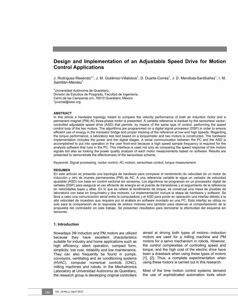
Figure 6. Harmonic distortion of for: the induction motor, 900 rpm at load condition.

Design and Implementation of an Adjustable Speed Drive for Motion Control Applications, J. Rodríguez‐Reséndiz et al. / 180‐194
Vol. 10 No.2, April 2012 188
MSPS. Autosequenced capability is preferred because of the sequential execution of the code, which provides 8 conversions in a single loop. Buffer of each conversion is saved on a 16-bit variable. Since the processor may not make use of floating point, a Q15 format library is used to calculate properly the quantities read by the ADC. The execution of the ADC sampling is enhanced in cascaded sequencer mode. Often, signals produced by an inductive load generate electrical
noise, which have to be decreased. In order to attenuate this phenomena a first-order filter is utilized by using an opamp, which is recommended to have: low supply voltage operation, voltage
noise (.√ ), low voltage offset (250μV). Cut-off
frequency is selected by and . These proprieties are also used to make the amplification, DC voltage offset, and also it offers high impedance to the next stage.
Figure 7. Harmonic distortion of for: the induction motor, 900 rpm at load condition.
Figure 8. Conditioning stage used in , , , , and Temp.
Design and Implementation of an Adjustable Speed Drive for Motion Control Applications, J. Rodríguez‐Reséndiz et al. / 180‐194
Journal of Applied Research and Technology 189
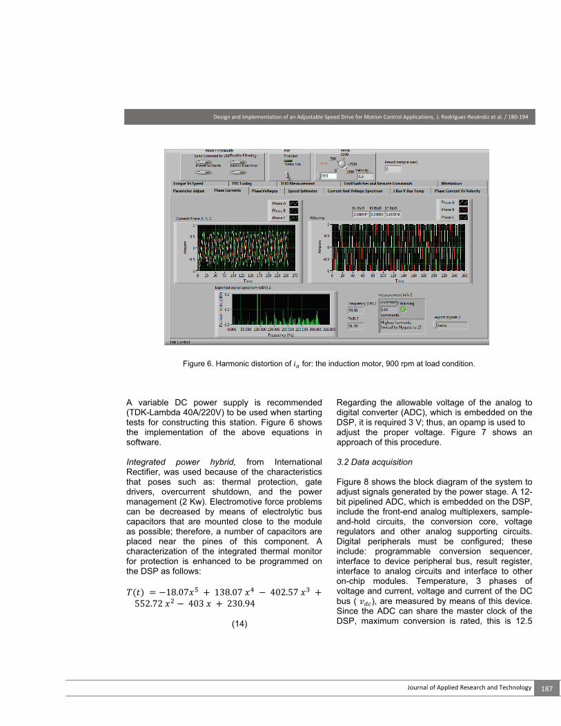
4. Software development Two software stages are programmed: DSP and computer, as shown in Figure 9. Therein the main routine of the DSP can be appreciated and how it interacts with the computer. DSP: A routine is programmed on the TMS320F2812. Tasks have been scheduled using interrupts permitted by the code composer studio compiler. The main routine runs at 20 KHz. Dead band is programmed and taken into account for the requirements of the power module. This parameter is fixed by considering specific factors [27] to prevent possible overheating in the IGBT module. In the same manner, Clarke and Park transforms, speed and flux estimators are programmed in the main loop. The C code is downloaded to the DSP that has a 128 Kwords Flash memory, which is essential to store the program when no energy is available. Three different variables can be requested by the user which include: torque, currents and voltages, temperature, estimated speed, actual speed, and so forth. These parameters are selected and arranged in a cluster to be sent in a frame. Baud rate of serial peripheral interface module is set in 0.5 Mbauds. Asynchronous mode has been selected due to its simplicity. Since the vector control used in this paper uses a constant model, macros are defined which simplify the process when changing among the
motors. Thus, the proposed methodology can be constructed using a programmable silicon device, that enables a rapid debug if there is an error. As a result, a data card is not needed to accomplish this task.
Computer: Serial interface is crucial to achieve the power spectrum inspection and tuning procedure. The FTDI 232 chip is used, in this sense a single chip USB is obtained, no external devices are needed such as resonator, crystal, resonator, resistances, capacitors. Regarding vendor ID, description ID, I/O configuration and serial number, they are stored in a 1024 bit internal EEPROM. This buffer permits the reconstruction of 3 different signals which have been selected by the user. G code is used to construct the user interface. Different blocks of LabVIEW are taken from the predetermined virtual instruments; these include: arithmetic, boolean, string, power spectrum, graph chart, to mention a few. It is recommended to have an interrupt model when developing the computer software because the sampling must be constant; the chip and the interface allows up to a 0.01 ms rate. The aforementioned methodology is enabled by means of the express tool called event case structure. Additional characteristics are offered by the interface such as the remote. As a result, a competitive software may be put into operation since a virtual instrument paradigm is carried out.
Figure 9. DSP and computer interaction.
Design and Implementation of an Adjustable Speed Drive for Motion Control Applications, J. Rodríguez‐Reséndiz et al. / 180‐194
Vol. 10 No.2, April 2012 190
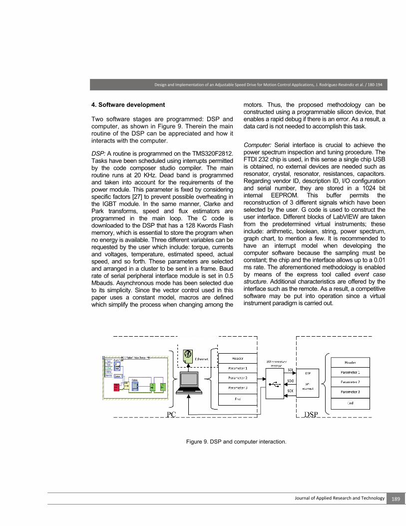
5. Results The interface and the test bench for measuring the torque contain an easy configuration because of the modular structure that posses. Therefore, certain measurements to check the performance are shown in Figures 10, 11, 12. The purpose of this evaluation is to study each motor in a wide range of speeds. Graphs were performed as follows:
Previous standstill tests of the motors were accomplished, parameter obtained are set in the program of the DSP.
A 0.753 Kw, 220V, 1.84A, four-pole induction motor is utilized as a load. Also, an electrodynamometer can be coupled instead of the motor.
A 0.5 Hp, 220V, ASD, V/f, Power Flex ASD is connected to the motor which emulates the load.
The torquemeter is placed among the motors, the ASD scheme proposed is connected to the motor.
The acquisition system (DSP-PC) is interconnected by USB, the user selects from the computer the variables to be monitored.
PI controllers are tuned manually from the computer. The user checks the step response of the motor while the proportional and integral constants, and
, respectively, are increased or decreased. Commercial ASD is adjusted at low speed and maximum current.
Parameters are measured and saved in the PC memory, then analyzed offline.
Figure 10. Off-line current consumption measurement of the induction motor in transient state.

Design and Implementation of an Adjustable Speed Drive for Motion Control Applications, J. Rodríguez‐Reséndiz et al. / 180‐194
Journal of Applied Research and Technology 191
Figure 11. Induction motor step response for 900 RPM in load condition. Red line: angle of estimated flux from 0 to 360°; blue line: current consumption in d axis; black line: estimated speed.
Figure 12. PM motor step response for 900 RPM in load condition. Red line: angle of estimated flux from 0 to 360°; blue line: current consumption in d axis; black line: estimated speed.
Design and Implementation of an Adjustable Speed Drive for Motion Control Applications, J. Rodríguez‐Reséndiz et al. / 180‐194
Vol. 10 No.2, April 2012 192
6. Conclusions The methodology presented herein fulfills the requirements to perform several experiments regarding electrical machines. It is demonstrated that the similar controller can be used for induction and PM motors. Thus, by changing the constant parameter block in the programming task, the electrical topology can manage an induction or PM motor. A second stage of this research consists of including the parameter estimation of rotor and stator variables; currently it is being carried out by means of neural networks. It was shown that it is not necessary to measure the terminal voltages to estimate the fluxes of the motors which avoids
complexity in the system. The proposed method is able to estimate the rotor position at low speeds. The project is being addressed for tasks of high performance motion control applications because of the accurate tracking of the speed and torque references. Acknowledgements The authors want to thank CONACyT and Universidad Autónoma de Querétaro for their financial support and for allowing the use of its premises, respectively. Thanks are also due to the companies that donate certain samples to be used in the experiments such as Texas Instruments, Maxim, Advanced Motion Control and Analog Devices.
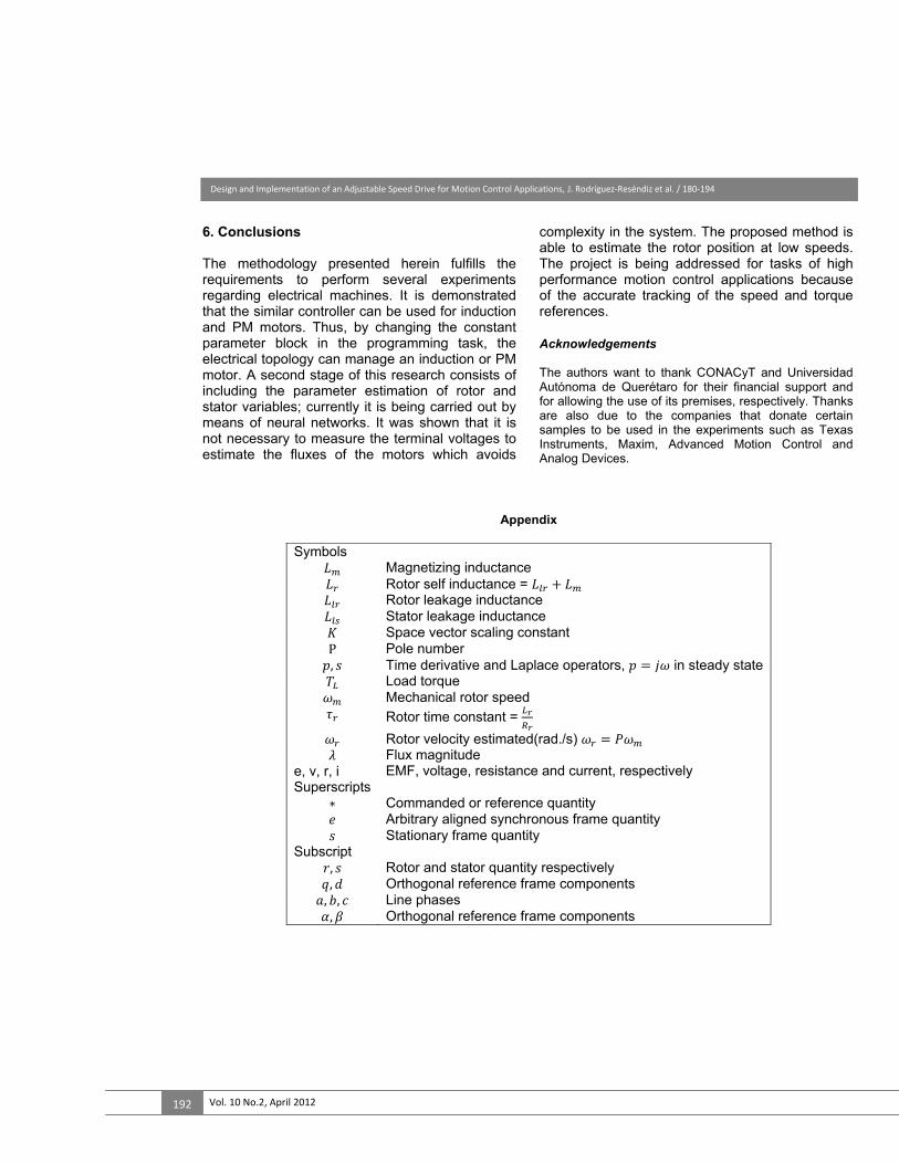
Appendix
Symbols
Magnetizing inductance Rotor self inductance = + Rotor leakage inductance Stator leakage inductance Space vector scaling constant P Pole number , Time derivative and Laplace operators, = in steady state Load torque Mechanical rotor speed Rotor time constant =
Rotor velocity estimated(rad./s) =
e, v, r, i Flux magnitude EMF, voltage, resistance and current, respectively
Superscripts ∗ Commanded or reference quantity Arbitrary aligned synchronous frame quantity Stationary frame quantity
Subscript , Rotor and stator quantity respectively , Orthogonal reference frame components , , Line phases , Orthogonal reference frame components

Design and Implementation of an Adjustable Speed Drive for Motion Control Applications, J. Rodríguez‐Reséndiz et al. / 180‐194
Journal of Applied Research and Technology 193
References [1] Mouloud A. Denai and Sid A. Attia., Fuzzy and Neural Control of an Induction Motor, Int. J. App. Math. Comput. Sci, vol. 12, No. 2, 2002, pp. 221-233. [2] Robert D. Lorenz, Thomas A. Lipo, and Donald W. Novotny., Motion Control With Induction Motors, in Proc. of IEEE, vol. 82, no. 8, Aug, 1994, pp. 1215-1240. [3] Darko Herco, et al., A DSP-Based Remote Control Laboratory, IEEE Trans. on Ind. Elec., vol. 54, no. 6, Dec, 2006, pp. 3057-3068. [4] J. Rodríguez-Reséndiz, E. A. Rivas-Araiza, G. Herrera-Ruiz, “Adjustable Speed Drive Project for Teaching a Servo Systems Course Laboratory”, IEEE Trans. on Edu., vol. 54, no. 4. Nov. 2011, pp. 657-666. [5] L. Harnefors, M. Jansson, R. Ottesten and K. Pietilainen, Unified Sensorless Vector Control of Synchronous and Induction Motors, IEEE Tran. Ind. Elec. vol. 50, no. 1, Feb. 2003, pp. 153-159. [6] A. M. Trzynadlowski., Field Orientation Principle in Control of Induction Motors, Kluwer Academic Publishers, 1994, pp. 176-180. [7] R. J. Wai, D. C. Liu and F.J. Lin, Rotor Time-constant Estimation Approaches Based on Energy Function and Sliding Mode for Induction Motor Drive, Elec. Pow. Sys. Res. vol. 52, Feb. 1999, pp. 229-239. [8]C. Cecati, Position Control of the Induction Motor Using a Passivity-Based Controller, IEEE Tran. Ind. App., vol. 36, no. 5, Oct. 2000, pp. 1277-1284. [9] M. A. Arjona, M. Cisneros-Gonzalez and C. Hernandez, Development of a synchronous-Generator Experimental Bench for Standstill Time-Domin Tests, J. of App. Res. and Tech., vol. 9, no. 2, Ago., 2011, pp. 117-128. [10] B. K. Bose Ed., Power Electronics and Variable Drives. Piscataway, NJ: IEEE Press 1996. [11] Q. D. Nguyen and S. Ueno, Analysis and Control of Nonsalient Permanent Magnet Axial Gap Self-Bearing Motor, IEEE Tran. Ind. Elec. vol. 58, no. 7, Jul. 2011, pp 2644-2652. [12] M. J. Corley and R. D. Lorenz, Rotor Position and Velocity Estimation for a Salient-Pole Permanent Magnet Synchronous Machine at Standstill and High Speeds, vo. 34, no. 4, Jul. 1998, pp. 784-789. [13] J. Rodríguez-Reséndiz, F. Mendoza-Mondragón, R. A. Gómez-Loenzo, M. A. Martínez-Hernandez, I. M. Santillan-Mendez and J. D. Mendiola-Santibañez, An
approach to motion control applications based on advanced programmable devices Int. J. Elect. Eng. Educ., vol. 49, Abr. 2012. [14] Rong Jong Wai and Jia Ming Chang., Intelligent Control of Induction Motor Drive Via Wavelet Neural Network, Journal of Electric Power Systems Research, vol. 61, no. 1, Feb, 2002, pp. 67-76. [15] Steve Bowling., Design And Implementation Of An Adjustable Speed Drive For Motion Control Applications R2, AN1078, Microchip Technology Inc., Europe, Mar, 2007. [16] Hyung-Min, Jang-Hwan and Seung-Ki Sul, Analysis of Multiphase Space Vector Pulse Width Modulation Based on Multiple d-q Spaces Concept, in IPEMC IEEE, vol. 3, no. 1, Aug. 2004, pp 1618 – 1624 [17] J. Rodriguez-Resendiz., et al., “Indirect Field Oriented Control of an Induction Motor Sensing DC-link Current,” Proc. IEEE CERMA., vol. 1, Sep. 2008, pp. 325-331. [18] Garcia, G.O. Stephan and R.M. Watanabe., Comparing the Indirect Field-Oriented Control with a Scalar Method, IEEE Transactions on Industrial Electronics, vol. 41, no 1, Apr., 1994, pp. 201-207 [19] C. A. González-Gutierrez, J. Rodríguez-Reséndiz, G. Mota-Valtierra, E. A. Rivaz-Araiza, J. D. Mendiola-Santibañez, R. Luna-Rubio, A PC-based architecture for parameter Analysis of Vector-Controlled Induction Motor Drive, Comp. Elec. Eng. vol. 37, no. 6, Nov. 2011, pp. 858-868. [20] H. Rehman., Design of Voltage Model Flux Observer, IEE Proc. Electr. Power Appl., vol. 151, no. 2, Mar., 2004, pp 129-134. [21] A. Mezouar, M. K. Fellah and S. Hadjeri., Robust Sliding Mode Control and Flux Observer for Induction Motor Using Singular Perturbation, Journal of Electrical Engineering, vol. 89, no. 3, Jun., 2007, pp. 193-203. [22] Marko Hinkkanen, Veli-Matti Leppänen, and Jorma Luomi, Flux., Observer Enhanced With Low-Frequency Signal Injection Allowing Sensorless Zero-Frequency Operation of Induction Motors, IEEE Transaction on Industry Applications, vo. 41, no. 1 Jan., 2005, pp. 52-59 [23] J. Rodriguez-Resendiz, E. A. Rivas-Araiza, G. Herrera-Ruiz, Virtual Instrumentation for Analysis of an Adjustable Speed Drive Parameters Based on DSC”, Proceedings of Texas Instruments, In European DSP in Education and Research Conference, vol. 4, no. 1, Dec., 2010, pp. 195-199.

Design and Implementation of an Adjustable Speed Drive for Motion Control Applications, J. Rodríguez‐Reséndiz et al. / 180‐194
Vol. 10 No.2, April 2012 194
[24] Yao Chen, Yibin Tong and Xinmin Jin, A Novel Algorithm of SVPWM Harmonic Analysis Based on PWM Rectifier, Proceedings of IEEE, vol. 27, no. 13, 2007, pp. 1752-1755. [25] Woo-Cheol Lee, Taeck-Kie Lee, and Dong-Seok Hyun., Comparison of Single-Sensor Current Control in the DC Link for Three-Phase Voltage-Source PWM Converters, IEEE Transaction on Industrial Electronics, vol. 48, no. 3, Jun., 2001, pp. 491-505. [26] Hu Xuezhi and Nan Guangqun., Research of Vector Variable Frequency System Based on TMS320F2812, Intelligent Computation Technology and Automation, vol. 2, no. 1, Oct. 2008, pp. 34-38. [27] Naomitsu Urasaki, Tomonobu Senjyo, Katsumi Uezato and Toshihisa Funabashi, An Adaptative Dead-Time Compensation Strategy for Voltage Source Inverter Fed Motor Drives, IEEE Trans. On Power Elec., vol. 20, no. 5, Sep. 2005. [28] M Melfi, S. Evon and R. McElveen, Induction versus permanent magnet motors, IEEE Ind. App. Mag., vol. 15, no. 6, Oct. 2009, pp. 28-35. [29] H. A. Toliyat, L. Hao, D. S. Shet and T. A. Nondahl, Position-Sensorless Control of Surcace-Mount Permantent-Magnet AC (PMAC) Motors at Low Speeds, IEEE Tran. Ind. Elec. vol. 49, no. 1, Feb. 2002, pp. 157-164.