Embed Size (px)
Citation preview
Anatomy, Neuroanatomy, and Physiology 35
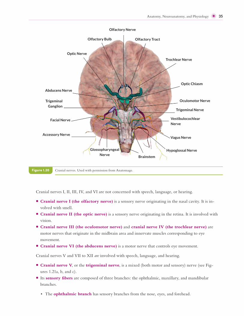
Cranial nerves I, II, III, IV, and VI are not concerned with speech, language, or hearing.
¡ Cranial nerve I (the olfactory nerve) is a sensory nerve originating in the nasal cavity. It is in-
volved with smell.
¡ Cranial nerve II (the optic nerve) is a sensory nerve originating in the retina. It is involved with
vision.
¡ Cranial nerve III (the oculomotor nerve) and cranial nerve IV (the trochlear nerve) are
motor nerves that originate in the midbrain area and innervate muscles corresponding to eye
movement.
¡ Cranial nerve VI (the abducens nerve) is a motor nerve that controls eye movement.
Cranial nerves V and VII to XII are involved with speech, language, and hearing.
¡ Cranial nerve V, or the trigeminal nerve, is a mixed (both motor and sensory) nerve (see Fig-
ures 1.21a, b, and c).
¡ Its sensory fibers are composed of three branches: the ophthalmic, maxillary, and mandibular
branches.
• The ophthalmic branch has sensory branches from the nose, eyes, and forehead.
Cranial nerves. Used with permission from Anatomage.Figure 1.20
Olfactory Nerve
Olfactory Tract
Trochlear Nerve
Optic Chiasm
Oculomotor Nerve
Trigeminal Nerve
Vestibulocochlear
Nerve
Vagus Nerve
Hypoglossal Nerve
Brainstem
Glossopharyngeal
Nerve
Accessory Nerve
Facial Nerve
Trigeminal
Ganglion
Abducens Nerve
Optic Nerve
Olfactory Bulb
Voice and Its Disorders 301
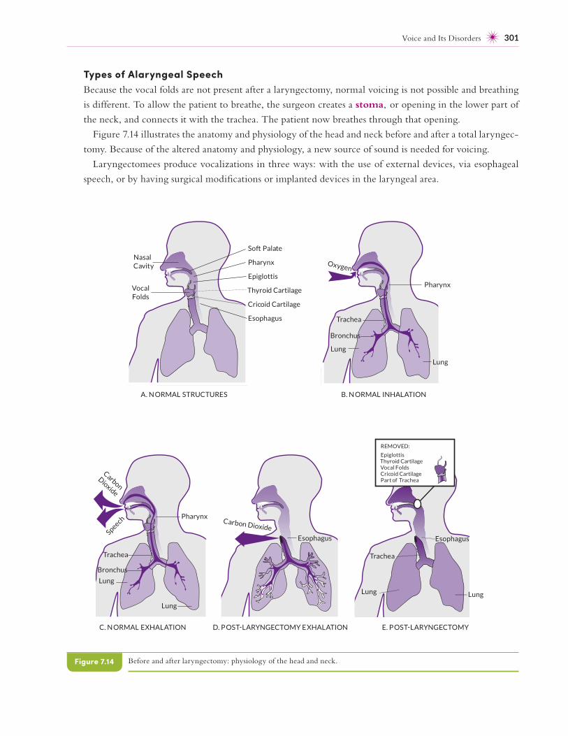
Types of Alaryngeal SpeechBecause the vocal folds are not present after a laryngectomy, normal voicing is not possible and breathing
is different. To allow the patient to breathe, the surgeon creates a stoma, or opening in the lower part of
the neck, and connects it with the trachea. The patient now breathes through that opening.
Figure 7.14 illustrates the anatomy and physiology of the head and neck before and after a total laryngec-
tomy. Because of the altered anatomy and physiology, a new source of sound is needed for voicing.
Laryngectomees produce vocalizations in three ways: with the use of external devices, via esophageal
speech, or by having surgical modifications or implanted devices in the laryngeal area.
Before and after laryngectomy: physiology of the head and neck.Figure 7.14
Cricoid Cartilage
So Palate
Pharynx
Epiglottis
Thyroid Cartilage
Esophagus
NasalCavity
Vocal Folds
Pharynx
Lung
Lung
Trachea
Carbon
Dioxide
Speech
Esophagus
Carbon Dioxide
Oxygen
Pharynx
Lung
Lung
Trachea
A. N ORMAL STRUCTURES B. N ORMAL INHALATION
C. N ORMAL EXHALATION D. POS LARYNGECTOMY EXHALATION
Bronchus
Bronchus
REMOVED:
EpiglottisThyroid CartilageVocal FoldsCricoid CartilagePart of Trachea
Esophagus
Lung
Trachea
Lung
E. POS LARYNGECTOMY
442 Chapter 10
• Training on /k/ and /ɡ/ may be inappropriate if the child’s velopharyngeal functioning is
inadequate.
• If stimulable, fricatives, affricates, or both may be trained; in any case, they may be trained after
stops are mastered.
• Frequent presentation of auditory and visual cues and modeling may be helpful.
• Compensatory articulatory positioning, where appropriate, may be taught.
• The clinician may teach the child to avoid posterior articulatory placements and to articulate
with less effort and facial grimacing.
• Tactile cues and instruction to improve tongue positioning may be useful.
• Some children benefit from a minimal pairs approach, especially if they delete final consonants.
For example, the SLP can contrast pairs, such as bee- beach, cow- couch, bye-bike, lie-line, and others.
¡ Research has not shown that work on non- speech, oral– motor blowing exercises is helpful for chil-
dren with cleft palates (Ruscello, 2008). Clinical outcome research is needed to assess the efficacy
of exercises, such as blowing horns, on the speech production of children with SSDs associated with
cleft palate.
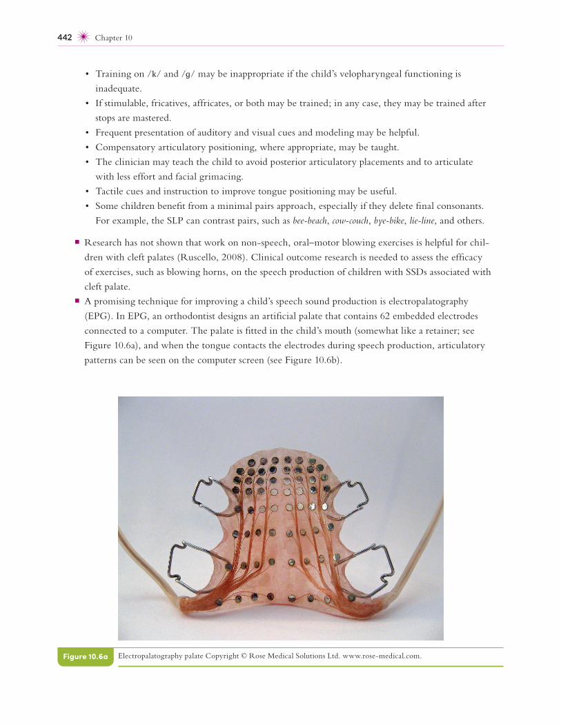
¡ A promising technique for improving a child’s speech sound production is electropalatography
(EPG). In EPG, an orthodontist designs an artificial palate that contains 62 embedded electrodes
connected to a computer. The palate is fitted in the child’s mouth (somewhat like a retainer; see
Figure 10.6a), and when the tongue contacts the electrodes during speech production, articulatory
patterns can be seen on the computer screen (see Figure 10.6b).
Electropalatography palate Copyright © Rose Medical Solutions Ltd. www .rose -medical .com.Figure 10.6a
Audiology and Hearing Disorders 543
• The in-the- canal model, which fi ts in the ear canal and is less visible. The receiver in the canal
(RIC) model has a case behind the ear that contains the aid’s amplifi er and microphone and a
small bud that contains the receiver located inside the ear canal. A tube connects the case to the
receiver.
• The completely-in-the- canal model, which is smaller and even less visible than the in-the-
canal model and terminates close to the tympanic membrane
• The in-the-ear model, which is a smaller unit that fi ts within the concha of the external ear.
¡ The analog hearing aid is not often used. They create patterns of electric voltage that correspond
to the sound input. All analog hearing aids consist of the same basic components: a microphone, an
amplifi er, a receiver, a power source (batteries), and volume control. Analog hearing aids now com-
prise a very small proportion of the total— approximately 10%.
¡ Digital hearing provide superior sound and connectivity to other devices (i.e., Bluetooth) and now
comprise 90% of the market.
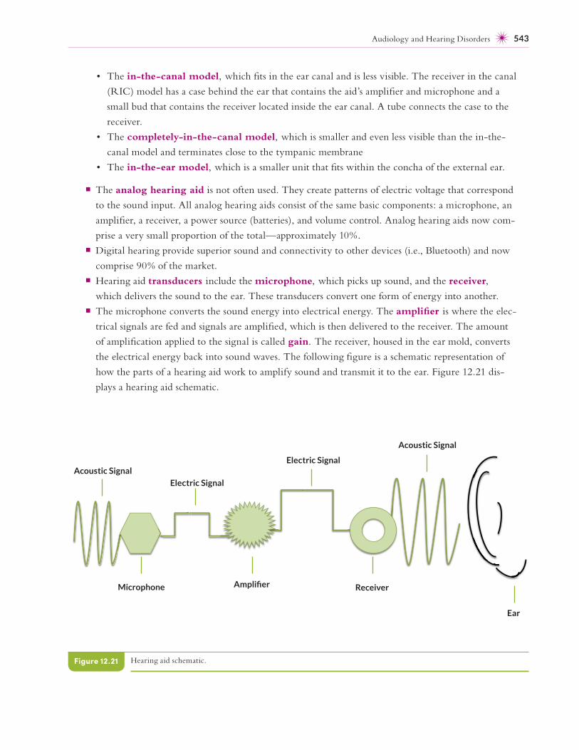
¡ Hearing aid transducers include the microphone, which picks up sound, and the receiver,
which delivers the sound to the ear. These transducers convert one form of energy into another.
¡ The microphone converts the sound energy into electrical energy. The amplifi er is where the elec-
trical signals are fed and signals are amplifi ed, which is then delivered to the receiver. The amount
of amplifi cation applied to the signal is called gain. The receiver, housed in the ear mold, converts
the electrical energy back into sound waves. The following fi gure is a schematic representation of
how the parts of a hearing aid work to amplify sound and transmit it to the ear. Figure 12.21 dis-
plays a hearing aid schematic.
Hearing aid schematic.Figure 12.21
Acoustic Signal
Microphone
Electric Signal
Amplifi er
Electric Signal
Receiver
Acoustic Signal
Ear