Embed Size (px)
Citation preview

1
© 2
014
Bak
er H
ughe
s In
corp
orat
ed. A
ll R
ight
s
Res
erve
d.
© 2014 BAKER HUGHES INCORPORATED. ALL RIGHTS RESERVED. TERMS AND CONDITIONS OF USE: BY ACCEPTING THIS DOCUMENT, THE RECIPIENT AGREES THAT THE DOCUMENT TOGETHER WITH ALL INFORMATION INCLUDED THEREIN IS THE
CONFIDENTIAL AND PROPRIETARY PROPERTY OF BAKER HUGHES INCORPORATED AND INCLUDES VALUABLE TRADE SECRETS AND/OR PROPRIETARY INF ORMATION OF BAKER HUGHES (COLLECTIVELY " INFORMATION"). BAKER HUGHES RETAINS ALL RIGHTS
UNDER COPYRIGHT LAWS AND TRADE SECRET LAWS OF THE UNITED STATES OF AMERICA AND OTHER COUNTRIES. THE RECIPIENT FURTHER AGREES TH AT THE DOCUMENT MAY NOT BE DISTRIBUTED, TRANSMITTED, COPIED OR REPRODUCED IN WHOLE OR
IN PART BY ANY MEANS, ELECTRONIC, MECHANICAL, OR OTHERWISE, WITHOUT THE EXPRESS PRIOR WRITTEN CONSENT OF BAKER HUGHES, AND MA Y NOT BE USED DIRECTLY OR INDIRECTLY IN ANY WAY DETRIMENTAL TO BAKER HUGHES’ INTEREST.
Analyzing the Correlations in Generalization of
the Reservoir Information in a Well Completion
Design Optimization using ICD’s along the
Horizontal section of a Wellbore
2014 DEVEX Conferences, Aberdeen, May 6th 2014
Morteza Akbari
6th and 7th May

2
© 2
014
Bak
er H
ughe
s In
corp
orat
ed. A
ll R
ight
s
Res
erve
d.
Introduction
EQUALIZERTM – Operating Envelope
EQUALIZERTM – Technology Portfolio
EQUALIZERTM – Design & Diagnostics Overview
EQUALIZERTM – Flow Performance Characteristics
EQUALIZERTM – Applications
■ Key technical factors that are affecting the horizontal well completions
■ Determining the potential actions to be taken in order to improve the influx and therefore
maximize the benefits of horizontal wells.
■ Analyzing horizontal wells applications using a reservoir simulator in order to understand the well
completion effects on the reservoir behavior.
3
© 2
014
Bak
er H
ughe
s In
corp
orat
ed. A
ll R
ight
s
Res
erve
d.
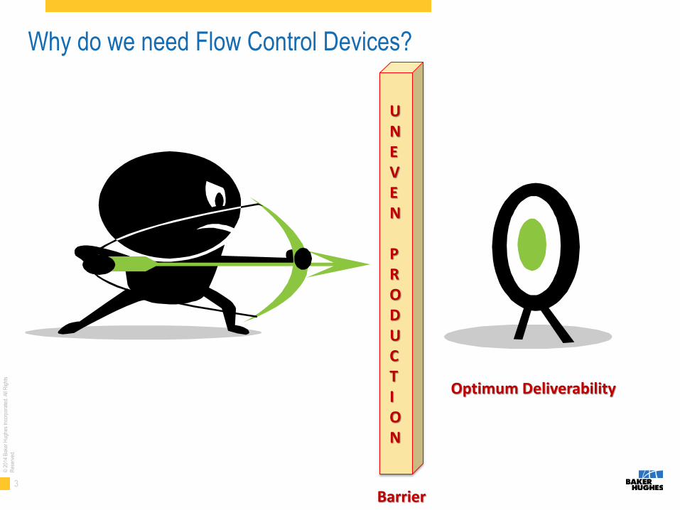
Why do we need Flow Control Devices?
Optimum Deliverability
Barrier
UNEVEN PRODUCTION

4
© 2
014
Bak
er H
ughe
s In
corp
orat
ed. A
ll R
ight
s
Res
erve
d.
Challenges facing production from long horizontal wells
• Uneven pressure drawdown along the wellbore due to long horizontal section (heel to toe effect)
• Permeability heterogeneity along open hole section
• Different mobility ratios of oil, gas and water
• Reservoir pressure difference along open hole section

5
© 2
014
Bak
er H
ughe
s In
corp
orat
ed. A
ll R
ight
s
Res
erve
d.
Baker Hughes as an Industry Leader in ICD Installations
EQUALIZER Technology – Enhanced hydrocarbon recovery
by delaying the onset of water or gas breakthrough by equalizing inflow along the length of a long horizontal lateral section.
– Field Proven
– Over 3 million feet installed in sand control and non-sand control applications ■ + 60,000 ICD Joints Downhole ■ + 600 miles
– + 1000 wells world wide: ■ Norway, Canada, Saudi Arabia,
Mexico, China, Russia, Indonesia, India, UAE, etc.

6
© 2
014
Bak
er H
ughe
s In
corp
orat
ed. A
ll R
ight
s
Res
erve
d.
© 2014 BAKER HUGHES INCORPORATED. ALL RIGHTS RESERVED. TERMS AND CONDITIONS OF USE: BY ACCEPTING THIS DOCUMENT, THE RECIPIENT AGREES THAT THE DOCUMENT TOGETHER WITH ALL INFORMATION INCLUDED THEREIN IS THE
CONFIDENTIAL AND PROPRIETARY PROPERTY OF BAKER HUGHES INCORPORATED AND INCLUDES VALUABLE TRADE SECRETS AND/OR PROPRIETARY INF ORMATION OF BAKER HUGHES (COLLECTIVELY " INFORMATION"). BAKER HUGHES RETAINS ALL RIGHTS
UNDER COPYRIGHT LAWS AND TRADE SECRET LAWS OF THE UNITED STATES OF AMERICA AND OTHER COUNTRIES. THE RECIPIENT FURTHER AGREES TH AT THE DOCUMENT MAY NOT BE DISTRIBUTED, TRANSMITTED, COPIED OR REPRODUCED IN WHOLE OR
IN PART BY ANY MEANS, ELECTRONIC, MECHANICAL, OR OTHERWISE, WITHOUT THE EXPRESS PRIOR WRITTEN CONSENT OF BAKER HUGHES, AND MA Y NOT BE USED DIRECTLY OR INDIRECTLY IN ANY WAY DETRIMENTAL TO BAKER HUGHES’ INTEREST.
EQUALIZERTM Operating Envelope

7
© 2
014
Bak
er H
ughe
s In
corp
orat
ed. A
ll R
ight
s
Res
erve
d.
Uneven Production from a Horizontal Lateral
Sections of the lateral are favored for production due to the influence of: • Frictional pressure drop in the completion string • Variations in Kv and Kh along the wellbore • Variations in fluid composition and mobility • Non-uniform reservoir pressure along the lateral length
ΔP1 ΔP2

8
© 2
014
Bak
er H
ughe
s In
corp
orat
ed. A
ll R
ight
s
Res
erve
d.
Physical phenomena in Horizontal Well
The Challenge: Water / Gas / Steam Breakthrough

9
© 2
014
Bak
er H
ughe
s In
corp
orat
ed. A
ll R
ight
s
Res
erve
d.
© 2014 BAKER HUGHES INCORPORATED. ALL RIGHTS RESERVED. TERMS AND CONDITIONS OF USE: BY ACCEPTING THIS DOCUMENT, THE RECIPIENT AGREES THAT THE DOCUMENT TOGETHER WITH ALL INFORMATION INCLUDED THEREIN IS THE
CONFIDENTIAL AND PROPRIETARY PROPERTY OF BAKER HUGHES INCORPORATED AND INCLUDES VALUABLE TRADE SECRETS AND/OR PROPRIETARY INF ORMATION OF BAKER HUGHES (COLLECTIVELY " INFORMATION"). BAKER HUGHES RETAINS ALL RIGHTS
UNDER COPYRIGHT LAWS AND TRADE SECRET LAWS OF THE UNITED STATES OF AMERICA AND OTHER COUNTRIES. THE RECIPIENT FURTHER AGREES TH AT THE DOCUMENT MAY NOT BE DISTRIBUTED, TRANSMITTED, COPIED OR REPRODUCED IN WHOLE OR
IN PART BY ANY MEANS, ELECTRONIC, MECHANICAL, OR OTHERWISE, WITHOUT THE EXPRESS PRIOR WRITTEN CONSENT OF BAKER HUGHES, AND MA Y NOT BE USED DIRECTLY OR INDIRECTLY IN ANY WAY DETRIMENTAL TO BAKER HUGHES’ INTEREST.
EQUALIZERTM Technology Portfolio

10
© 2
014
Bak
er H
ughe
s In
corp
orat
ed. A
ll R
ight
s
Res
erve
d.
EQUALIZER Technology Portfolio
ICD
(Inflow Control Device)
EQAULIZER Select
EQUALIZER HELIX
Non-Sand Control
(Consolidated Formation)
EQUALIZER-CF
Sand Control Screen Type
BakerWrap
Wrap-on-Pipe ScreenExcluder2000
Premium Mesh Screen
BakerWeld
Jacketed Sand Screen
Accessories
MTV
(Multi Tasking Valve)
MPas PackerRE Packer
(Reactive Element) Sliding Sleeve

11
© 2
014
Bak
er H
ughe
s In
corp
orat
ed. A
ll R
ight
s
Res
erve
d.
Types of Flow Control Devices
Frictional Geometry
Restriction Geometry
Autonomous Geometry
∆𝑃 =𝜌
2
𝑄
𝐴
2 ∝ 𝜌𝑄2
∆𝑃 =128𝜇𝐿𝑄
𝜋𝑑4 ∝ 𝜇𝑄
∆𝑃 ∝ 𝑎2𝑅𝑒𝑏2 +𝑎1𝑅𝑒𝑏1 + 𝑎2𝑅𝑒𝑏2
1 +𝑅𝑒𝑡
𝑐 𝑑
Big flow area, low velocity, viscosity sensitive
Small flow area, high velocity, partially viscosity insensitive
Varies; big flow area, low velocity, viscosity insensitive

12
© 2
014
Bak
er H
ughe
s In
corp
orat
ed. A
ll R
ight
s
Res
erve
d.
PICD Geometry Types
■ EQUALIZER SELECT: Field-adjustable version of the
hybrid ICD. The desired flow restriction setting is controlled
by selection of the quadrant which is open for flow.
■ EQUALIZER HELIX: Helical-channel PICD
design creates the desired flowing pressure loss
via friction as fluid passes through the channel(s).

13
© 2
014
Bak
er H
ughe
s In
corp
orat
ed. A
ll R
ight
s
Res
erve
d.
Visualizing the Flow Path
– Equalizer HELIX
– Equalizer SELECT

14
© 2
014
Bak
er H
ughe
s In
corp
orat
ed. A
ll R
ight
s
Res
erve
d.
What Do We Design For?
No plugging over the life of the well
Minimal or no erosion
Sufficient pressure drop to
equalize flow over well life
Greater economic efficiency

15
© 2
014
Bak
er H
ughe
s In
corp
orat
ed. A
ll R
ight
s
Res
erve
d.
Decision Making Process
Determine the need for Sand
Control
Establish Minimum Number of
Flow Control Devices using
Critical Velocity
Determine Screen/Barrier
Length
Establish Maximum Number of
Devices using Performance
Curves
Determine Packer
Number and Placement
Model Performance over the Life of the Well

16
© 2
014
Bak
er H
ughe
s In
corp
orat
ed. A
ll R
ight
s
Res
erve
d.
The Need for Modeling

17
© 2
014
Bak
er H
ughe
s In
corp
orat
ed. A
ll R
ight
s
Res
erve
d.
ICD completion design requires careful modeling of several
parameters including:
• Fluid saturations • Variations in fluid properties • Reservoir pressure • Production drawdown • Flow rates at the sand face and into the completion • Variances in permeability along length of the wellbore • Maximum flow rate per joint to not exceed the erosion velocity • Minimum flow rate per joint to promote flow control • Minimum pressure drop through the completion to control the reservoir fluids • Effect of compartmentalization of the pay zone

18
© 2
014
Bak
er H
ughe
s In
corp
orat
ed. A
ll R
ight
s
Res
erve
d.
Compartmentalization in ICD completions
Heterogeneity and ICD completion design

19
© 2
014
Bak
er H
ughe
s In
corp
orat
ed. A
ll R
ight
s
Res
erve
d.
© 2014 BAKER HUGHES INCORPORATED. ALL RIGHTS RESERVED. TERMS AND CONDITIONS OF USE: BY ACCEPTING THIS DOCUMENT, THE RECIPIENT AGREES THAT THE DOCUMENT TOGETHER WITH ALL INFORMATION INCLUDED THEREIN IS THE
CONFIDENTIAL AND PROPRIETARY PROPERTY OF BAKER HUGHES INCORPORATED AND INCLUDES VALUABLE TRADE SECRETS AND/OR PROPRIETARY INF ORMATION OF BAKER HUGHES (COLLECTIVELY " INFORMATION"). BAKER HUGHES RETAINS ALL RIGHTS
UNDER COPYRIGHT LAWS AND TRADE SECRET LAWS OF THE UNITED STATES OF AMERICA AND OTHER COUNTRIES. THE RECIPIENT FURTHER AGREES TH AT THE DOCUMENT MAY NOT BE DISTRIBUTED, TRANSMITTED, COPIED OR REPRODUCED IN WHOLE OR
IN PART BY ANY MEANS, ELECTRONIC, MECHANICAL, OR OTHERWISE, WITHOUT THE EXPRESS PRIOR WRITTEN CONSENT OF BAKER HUGHES, AND MA Y NOT BE USED DIRECTLY OR INDIRECTLY IN ANY WAY DETRIMENTAL TO BAKER HUGHES’ INTEREST.
EQUALIZERTM Flow Performance Characteristics
20
© 2
014
Bak
er H
ughe
s In
corp
orat
ed. A
ll R
ight
s
Res
erve
d.
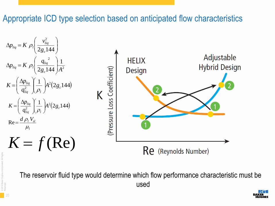
Appropriate ICD type selection based on anticipated flow characteristics
The reservoir fluid type would determine which flow performance characteristic must be
used
14421
1
1442
1442
2
2
2
2
2
c
lliq
liq
c
liq
lliq
c
liq
lliq
gAq
pK
Ag
qKp
g
vKp
Re
14421 2
2
l
sll
c
lliq
liq
Vd
gAq
pK
(Re)fK

21
© 2
014
Bak
er H
ughe
s In
corp
orat
ed. A
ll R
ight
s
Res
erve
d.
Adjustable Hybrid Design Flow Performance Characteristic

22
© 2
014
Bak
er H
ughe
s In
corp
orat
ed. A
ll R
ight
s
Res
erve
d.
Low flow velocity design and high flow area to avoid erosion & plugging issues

23
© 2
014
Bak
er H
ughe
s In
corp
orat
ed. A
ll R
ight
s
Res
erve
d.
The Flow Resistance Rating impact on the flow performance

24
© 2
014
Bak
er H
ughe
s In
corp
orat
ed. A
ll R
ight
s
Res
erve
d.
© 2014 BAKER HUGHES INCORPORATED. ALL RIGHTS RESERVED. TERMS AND CONDITIONS OF USE: BY ACCEPTING THIS DOCUMENT, THE RECIPIENT AGREES THAT THE DOCUMENT TOGETHER WITH ALL INFORMATION INCLUDED THEREIN IS THE
CONFIDENTIAL AND PROPRIETARY PROPERTY OF BAKER HUGHES INCORPORATED AND INCLUDES VALUABLE TRADE SECRETS AND/OR PROPRIETARY INF ORMATION OF BAKER HUGHES (COLLECTIVELY " INFORMATION"). BAKER HUGHES RETAINS ALL RIGHTS
UNDER COPYRIGHT LAWS AND TRADE SECRET LAWS OF THE UNITED STATES OF AMERICA AND OTHER COUNTRIES. THE RECIPIENT FURTHER AGREES TH AT THE DOCUMENT MAY NOT BE DISTRIBUTED, TRANSMITTED, COPIED OR REPRODUCED IN WHOLE OR
IN PART BY ANY MEANS, ELECTRONIC, MECHANICAL, OR OTHERWISE, WITHOUT THE EXPRESS PRIOR WRITTEN CONSENT OF BAKER HUGHES, AND MA Y NOT BE USED DIRECTLY OR INDIRECTLY IN ANY WAY DETRIMENTAL TO BAKER HUGHES’ INTEREST.
EQUALIZERTM Applications

25
© 2
014
Bak
er H
ughe
s In
corp
orat
ed. A
ll R
ight
s
Res
erve
d.
A Variety of Applications
■ Reservoir type: sandstone &
carbonate
■Well Type: producer & injector &
storage wells
■ Fluid Type: oil & gas
■ Completion type: Standalone or
Gravel pack
■ Single or Multi lateral
■Well Deviation: horizontal or vertical
(long interval – thickness and high
permeability contrast)
■ SAGD

26
© 2
014
Bak
er H
ughe
s In
corp
orat
ed. A
ll R
ight
s
Res
erve
d.
Single lateral Sandstone – Water Control ICD Controlling water in Oil producer in a sandstone formation

27
© 2
014
Bak
er H
ughe
s In
corp
orat
ed. A
ll R
ight
s
Res
erve
d.
Single lateral Sandstone – Water/Gas Control ICD controlling water and gas in Oil producer
1600’ horizontal
3200’ horizontal
6400’ horizontal Standard
Screen PICD
Standard Screen
PICD
Standard Screen
PICD
Standard Screen
PICD

28
© 2
014
Bak
er H
ughe
s In
corp
orat
ed. A
ll R
ight
s
Res
erve
d.

29
© 2
014
Bak
er H
ughe
s In
corp
orat
ed. A
ll R
ight
s
Res
erve
d.

30
© 2
014
Bak
er H
ughe
s In
corp
orat
ed. A
ll R
ight
s
Res
erve
d.
Questions ???