Embed Size (px)
Citation preview

Data SheetD-NCA-TB84TE_2
Analytical InstrumentsAdvantage Series™
Two-Electrode Conductivity AnalyzerTB84TE
TB84TE - a leap forward intwo-electrode conductivity
analyzer technology.
Patented smart key menu programming.
Superior accuracy in low conductivity andpure water applications.
Two fully programmable isolated outputs:Zero to 20 mA/four to 20 mA.
Three fully programmable relay outputs.
Compatible with complete line of ABBtwo-electrode conductivity sensors.
Back-lit display for easy viewing.
Adjustable damping.
Hold output function: Holds all outputs or anyindividual output.
Programmable security codes andconfiguration lockout.
Universal power supply: 120/240 VAC,50/60 Hz. Voltage range is 94 to 276 VAC.
Temperature compensation modes includethree for pure water.
NEMA 4X/IP65 housing: Cast aluminum withcorrosion resistant powder coat finish.
FM and CSA non-incentive agency approvals.CE Mark.
2
Analytical InstrumentsAdvantage SeriesTM Two-Electrode Conductivity Analyzer D-NCA-TB84TE_2
Advantage Series™ Two-Wire,Two-Electrode Conductivity
The ABB TB84TE Advantage™ Conductivity Analyzer isa unique and advanced microprocessor-based instru-ment. Smart keys on the front panel provide localprogramming of all analyzer functions. Easy-to-followinstructions appear above each smart key. A secondarydisplay clearly defines each menu option during pro-gramming. When the analyzer is in the normal operatingmode, the secondary display shows several usefulparameters. This innovative, user-friendly interfaceprovides straightforward analyzer operation, configura-tion, and calibration. Standard outputs include twoisolated analog (current) outputs and three relay out-puts. The analog outputs can be configured for theprocess variable (PV) and/or temperature. The relayoutputs can be configured for the PV, temperature,diagnostics, cycle timer controller, or sensor cleaner.
The TB84TE analyzer is compatible with all ABBtwo-electrode conductivity sensors. It automaticallyranges itself across three decades of conductivityresolution for any single cell constant. Two-electrodesensors provide accurate conductivity measurements inlower conductivity solutions and pure water. Precalibra-tion is accomplished by programming the cell constantof the sensor during configuration. Careful selection ofelectrode materials (316 stainless steel standard),insulator materials, and electrode spacing providesrugged sensors and reduced sensor maintenance.Sensor diagnostics include sensor polarization, andopen or shorted temperature compensator/cabling.
The TB84TE analyzer meets current CE, NEMA 4X, andIP65 requirements.
Two-Electrode Sensor Compatibility
The analyzer accepts inputs from all ABB two-electrodesensors. A menu choice during configuration makeschanging from one cell constant to another easy. Nojumpers or manual adjustments are required.
Basic or Advanced Programming
The Basic or Advanced programming mode can bechosen at the time of purchase. The Advanced mode hasan expanded set of functions intended for complexapplications. Separating the Basic and Advanced modessimplifies setup and calibration activities. The Advancedconfiguration choices are:• Concentration analyzer: User-defined through
a six-point conductivity versus concentrationlinear curve fit where output follows concentration.Engineering unit choices are percent (%), parts permillion (ppm), parts per billion (ppb), and user-defined.
• Temperature compensation types: Pure waterneutral salt, pure water trace base, pure watertrace acid, user-defined function generator.
• Analog pulse diagnostic output.
• Nonlinear output: User-defined through a six-point conductivity versus desired current outputthat best fits the nonlinear relationship.
• Expanded relay functions and flexibility.
Analog Outputs
The analyzer has two isolated analog outputs (AO1 andAO2). Each is user-configurable as either a zero to 20 ora four to 20-milliampere signal. AO1 is dedicated to thePV while AO2 is configurable for either the PV or temper-ature. A two-point calibration method applies to bothanalog outputs. This allows adjustment of the analogoutputs to compensate for other devices in the loop thatmay not be calibrated. Entering the PV or temperatureendpoints in reverse order allows for reverse-actingoutputs.
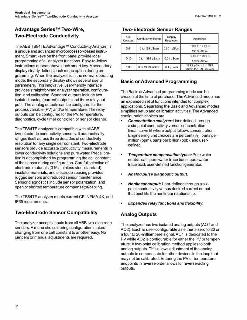
Two-Electrode Sensor RangesCell
Constant Conductivity Range Display Resolution Autorange
1.999 to 19.99 to
199.9 µS/cm
19.99 to 199.9 to
1,999 µS/cm
1.00 0 to 19.99 mS/cm 0.1 µS/cm 199.9 µS/cm to 1,999 µS/cm to 19.99 mS/cm
0.01 0 to 199 µS/cm 0.001 µS/cm
0.10 0 to 1,999 µS/cm 0.01 µS/cm

3
Analytical InstrumentsAdvantage SeriesTM Two-Electrode Conductivity Analyzer D-NCA-TB84TE_2
A capacitive type lag, applied via the damping function,is useful in process environments where noise ispresent. Damping is supported for both analog outputsand the displayed PV, and has a maximum value of99.9 seconds. One damping value affects both analogoutputs and the displayed PV in basic configurations.Individual damping values affect each analog output andthe displayed PV in advanced configurations.
Relay Outputs
The analyzer has three relay outputs available (RO1,RO2, RO3). Each is jumper selectable as eithernormally open (NO) or normally closed (NC). RELAY,followed by the corresponding relay number, appears onthe display when a relay activates. The functionality ofeach relay output depends on the configuration mode.Table 1 shows the possible functionality of each relayoutput for basic and advanced configurations. Advancedprogramming allows all function choices shown in Table1 for each of the three relay outputs.
Diagnostics
The TB84TE analyzer constantly monitors both thesensor and the analyzer. This helps to ensure reliabilityand accuracy. Upon detection of a diagnostic condition,the analyzer provides diagnostic notification by flashingFAULT on the display and supplying a pulse on AO1 (ifactivated). Pressing the FAULT info smart key stopsFAULT from flashing and provides, on the secondarydisplay, a short description and fault code. FAULTremains on until resolution of the problem. Sensor faultsthat activate the diagnostic notification are:• Sensor polarization.• Shorted or open temperature compensator.
Hold Output
The analyzer has a hold output state that improves plantsafety and process integrity during maintenance andcalibration. When activated, HOLD appears at the top ofthe display. Upon release of the hold state, HOLDdisappears. When the sensor cleaner option is chosen,the analyzer provides the option of holding all analog andrelay outputs during the cleaning cycle. The analogoutputs can be held to any preselected level. The relayoutputs can be held individually to any active or inactivestate. This is useful for checking and exercising anyexternal devices connected to the analyzer.
Diagnostic Pulse
The analog output is fully scalable over any conductivityor concentration range. Advanced configurations allowpulsing of AO1 during a diagnostic condition.
When the diagnostic pulse is active, the output ismodulated for one second out of a six-second repeatingcycle to a configuration selectable level ranging from oneto 100 percent of span (0.16 to 16 milliamperes for a fourto 20-milliampere output or 0.20 to 20 milliamperes for azero to 20-milliampere output). Should the actual outputof the analyzer be below 12 milliamperes, the pulse willadd current; if the actual output is at or above 12milliamperes, it will subtract current. This providesremote notification of a problem with proper configurationof a digital control system (DCS), programmable logiccontroller (PLC), or chart recorder.
High and low alarms can be chosen for the PV andtemperature in either degrees Celsius or degreesFahrenheit. Each has a user-selectable deadband andtime delay designed to control relay functions andprevent problems like relay chatter. The diagnosticrelays can be linked to sensor diagnostics, analyzerdiagnostics, or all diagnostic conditions. The high andlow cycle timer has adjustable set points, cycle time,and on time. The cycle timer allows a waiting period tosee the results of chemical addition by interrupting thefeed. The sensor cleaner feature provides for cycle time,on time, and recovery time programming. This makesset up and operation of the analyzer with the ABBhydraulic sensor cleaner or Model TB18 Safe-T-Clean®
Sensor Valve easy and trouble free.
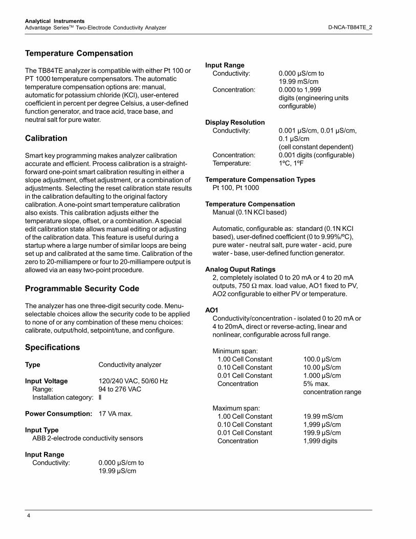
Table 1. Relay Output Functionality 1
Basic Adv Basic Adv Basic AdvHigh or low PV alarm • • • • • •High or low temperature alarm (ºC or ºF) • • • • •
Diagnostics alarm • • • •
High or low cycle timer • • •
Sensor cleaner 2 • • •
Notes:1. • = available2. If a relay output has been configured as a sensor cleaner, no other relay output can be used for this function
FunctionRO1 RO2 RO3
4
Analytical InstrumentsAdvantage SeriesTM Two-Electrode Conductivity Analyzer D-NCA-TB84TE_2
Temperature Compensation
The TB84TE analyzer is compatible with either Pt 100 orPT 1000 temperature compensators. The automatictemperature compensation options are: manual,automatic for potassium chloride (KCl), user-enteredcoefficient in percent per degree Celsius, a user-definedfunction generator, and trace acid, trace base, andneutral salt for pure water.
Calibration
Smart key programming makes analyzer calibrationaccurate and efficient. Process calibration is a straight-forward one-point smart calibration resulting in either aslope adjustment, offset adjustment, or a combination ofadjustments. Selecting the reset calibration state resultsin the calibration defaulting to the original factorycalibration. A one-point smart temperature calibrationalso exists. This calibration adjusts either thetemperature slope, offset, or a combination. A specialedit calibration state allows manual editing or adjustingof the calibration data. This feature is useful during astartup where a large number of similar loops are beingset up and calibrated at the same time. Calibration of thezero to 20-milliampere or four to 20-milliampere output isallowed via an easy two-point procedure.
Programmable Security Code
The analyzer has one three-digit security code. Menu-selectable choices allow the security code to be appliedto none of or any combination of these menu choices:calibrate, output/hold, setpoint/tune, and configure.
Specifications
Type Conductivity analyzer
Input Voltage 120/240 VAC, 50/60 HzRange: 94 to 276 VACInstallation category: II
Power Consumption: 17 VA max.
Input TypeABB 2-electrode conductivity sensors
Input RangeConductivity: 0.000 µS/cm to
19.99 µS/cm
Input RangeConductivity: 0.000 µS/cm to
19.99 mS/cmConcentration: 0.000 to 1,999
digits (engineering unitsconfigurable)
Display ResolutionConductivity: 0.001 µS/cm, 0.01 µS/cm,
0.1 µS/cm(cell constant dependent)
Concentration: 0.001 digits (configurable)Temperature: 1ºC, 1ºF
Temperature Compensation TypesPt 100, Pt 1000
Temperature CompensationManual (0.1N KCI based)
Automatic, configurable as: standard (0.1N KCIbased), user-defined coefficient (0 to 9.99%/ºC),pure water - neutral salt, pure water - acid, purewater - base, user-defined function generator.
Analog Ouput Ratings2, completely isolated 0 to 20 mA or 4 to 20 mAoutputs, 750 Ω max. load value, AO1 fixed to PV,AO2 configurable to either PV or temperature.
AO1Conductivity/concentration - isolated 0 to 20 mA or4 to 20mA, direct or reverse-acting, linear andnonlinear, configurable across full range.
Minimum span:1.00 Cell Constant 100.0 µS/cm0.10 Cell Constant 10.00 µS/cm0.01 Cell Constant 1.000 µS/cmConcentration 5% max.
concentration range
Maximum span:1.00 Cell Constant 19.99 mS/cm0.10 Cell Constant 1,999 µS/cm0.01 Cell Constant 199.9 µS/cmConcentration 1,999 digits

5
Analytical InstrumentsAdvantage SeriesTM Two-Electrode Conductivity Analyzer D-NCA-TB84TE_2
AO2Conductivity/concentration/temperature (ºC or ºF) -Isolated 0 to 20 mA or 4 to 20 mA, direct orreverse-acting, configurable across full range
Minimum span:1.00 Cell Constant 100.0 µS/cm0.10 Cell Constant 10.00 µS/cm0.01 Cell Constant 1.00 µS/cmConcentration 5% max.
concentration rangeTemperature 10ºC, 18ºF
Maximum span:1.00 Cell Constant 19.99 mS/cm0.10 Cell Constant 1,999 µS/cm0.01 Cell Constant 199.9 µS/cmConcentration 1,999 digitsTemperature 300ºC, 540ºF
Relay OutputsForm C, SPDT relays that are jumper selectableas either normally open or normally closed. Referto Table 1 to see functionality of each relay outputin basic and advanced configurations.
Ratings:
Max. AC capacity 100 VA, 240 VAC, 3 AMax. DC capacity 50 W, 24 VDC, 2 A
High and low set points(Basic and Advanced configurations):
Source: Conductivity and concentrationHigh/low/deadband Software configurableDelay value range 00.0 to 99.9 min.
Source: Temperature (ºC to ºF)High and low range 0º to 300ºC or
32º to 572ºFDeadband range 0º to 10ºC or
0º to 18ºFDelay value range 00.0 to 99.9 min.
High or low cycle timer(Advanced configurations only)
Source: Conductivity and concentrationTurn on range Software configurableCycle time and on time range
00.0 to 99.9 min.
Sensor Cleaner (advanced configurations only)Cycle time range 00.0 to 99.9 hr.On time range 00.0 to 99.9 min.Recovery time range 00.0 to 99.9 min.
Turn on range Software configurable
Nonlinearity and Repeatability
Conductivity:Display ±1.0% of
measurement rangeper decade.
Output ±0.02 mA at fullscale outputsettings
Temperature: 1ºC
Maximum Sensor Cable Length30.5 m (100 ft)
Turn On Time 2 secs typical,4 secs max.
Load Resistance Range (analog outputs)750 Ω max.
Damping Continuously adjustablefrom 00.0 to 99.9 secs
Dynamic Response 3 sec for 90% step changewith 00.0 sec damping
Mounting Position EffectNone
EnvironmentalTemperature:
Operating: -20º to 60ºC (-4º to 140ºF)Storage: -40º to 70ºC (-40º to 158ºF)
Humidity (operating and storage):Will meet specifications to95% RH
HousingNEMA 4X and IP65, aluminum alloy with corrisionresistant polyester powder coating.
Conduit Connection5 total, 2 each 0.875-in. holes in enclosure thataccept 1/2-in. hubs, 3 each 0.600-in. holes thataccept PG9 hubs.
6
Analytical InstrumentsAdvantage SeriesTM Two-Electrode Conductivity Analyzer D-NCA-TB84TE_2
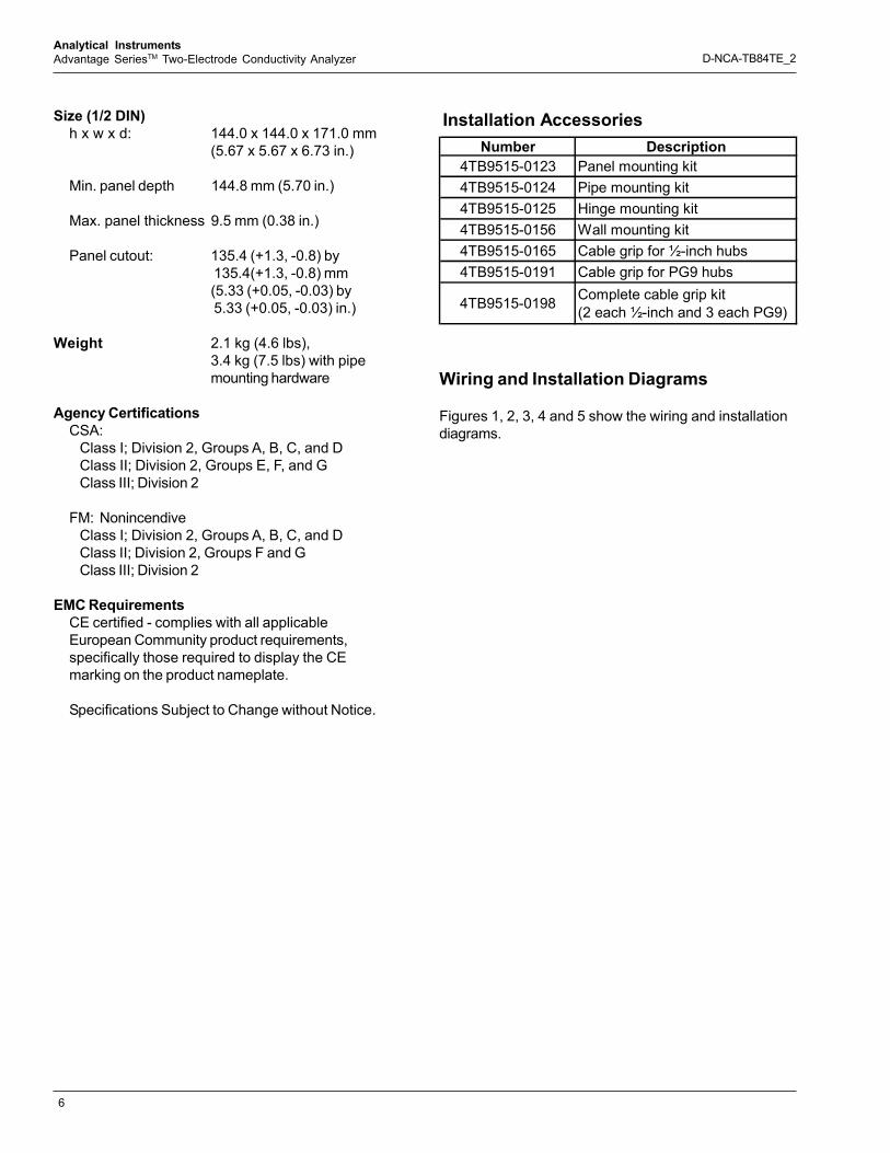
Size (1/2 DIN)h x w x d: 144.0 x 144.0 x 171.0 mm
(5.67 x 5.67 x 6.73 in.)
Min. panel depth 144.8 mm (5.70 in.)
Max. panel thickness 9.5 mm (0.38 in.)
Panel cutout: 135.4 (+1.3, -0.8) by 135.4(+1.3, -0.8) mm(5.33 (+0.05, -0.03) by 5.33 (+0.05, -0.03) in.)
Weight 2.1 kg (4.6 lbs),3.4 kg (7.5 lbs) with pipemounting hardware
Agency CertificationsCSA:
Class I; Division 2, Groups A, B, C, and DClass II; Division 2, Groups E, F, and GClass III; Division 2
FM: NonincendiveClass I; Division 2, Groups A, B, C, and DClass II; Division 2, Groups F and GClass III; Division 2
EMC RequirementsCE certified - complies with all applicableEuropean Community product requirements,specifically those required to display the CEmarking on the product nameplate.
Specifications Subject to Change without Notice.
Wiring and Installation Diagrams
Figures 1, 2, 3, 4 and 5 show the wiring and installationdiagrams.
Installation AccessoriesNumber Description
4TB9515-0123 Panel mounting kit4TB9515-0124 Pipe mounting kit4TB9515-0125 Hinge mounting kit4TB9515-0156 Wall mounting kit4TB9515-0165 Cable grip for ½-inch hubs4TB9515-0191 Cable grip for PG9 hubs
4TB9515-0198 Complete cable grip kit (2 each ½-inch and 3 each PG9)

7
Analytical InstrumentsAdvantage SeriesTM Two-Electrode Conductivity Analyzer D-NCA-TB84TE_2
Figure 1. Wiring
Figure 2. Panel Mounting
SENSOR CONNECTIONS OUTPUT CONNECTIONS
POWERCONNECTIONS
TB2
123
123456789
10
GREENRED
WHITEBLACKBLUE
YELLOWHVY GRN
12345678
DRIVE
DRIVESENSE
SHIELD
RTDRTD
SENSE
LINE (L1)
1 (+)
NEUTRAL (L2)
1 ()
CAUTION
TB1
TB3
REAR VIEW
EXTERNAL GROUNDTERMINAL
INPUTPOWER
INTERNAL GROUNDTERMINALS
SENSOR CABLETO BE SEALEDIN CONDUIT
TOTB2
ANALOGOUTPUT 1
ANALOGOUTPUT 2
RELAY 1RELAY 2RELAY 3LINENEUTRAL
EARTH
2 (+)2 ()
112233
FOR84ECONLY
FOR84ECONLY
REAR COVERREMOVED
EXTERNALGROUND SCREW
T01088E
PANEL GASKET
PANEL
9.50.38
MAXIMUM PANELTHICKNESS
EPTHNEL D
PANELCUTOUT
MINIMUM PA = 144.8 MM (5.70 IN.)
11.90.47
135.4 +1.3–0.8
5.33 +0.05–0.03
135.4 +1.3–0.8
5.33 +0.05–0.03
11.90.47
LOCK ASHER (4)
REAR VIEW
PANEL MOUNTINGBRACKET (4)
3/8-IN.W
3/8-16 x 1/2-IN.HEX SCREW (4)
PANEL MOUNTINGSCREWS (4)

8
Analytical InstrumentsAdvantage SeriesTM Two-Electrode Conductivity Analyzer D-NCA-TB84TE_2
Figure 3. Wall/Hinge Rear Mounting
Figure 4. Wall (Side) Mounting
WALL
FASTENERS FORWALL (SUPPLIED BY
OTHERS)
3/8" NUT (8)3/8"
FLATWASHER (8)
3/8" FLATWASHER (4)
3/8" LOCKWASHER (8)
3/8" LOCKWASHER (4)
"L" BRACKET
FRONT VIEWTOP VIEW
3/8" X 3/4"BOLT (8)
S.S. HINGE
PIPE MOUNTBRACKET
3/8" X 5/8"BOLT
WALL
PIPEMOUNT
BRACKET3/8"
FLATWASHER (4)
3/8" X 5/8"BOLT (4)
3/8"LOCKWASHER (4)
FASTENERS FOR WALL(SUPPLIED BY OTHERS)
WALL
DIMENSIONS
MILLIMETERSINCHES
2278.94

9
Analytical InstrumentsAdvantage SeriesTM Two-Electrode Conductivity Analyzer D-NCA-TB84TE_2
Figure 5. Pipe Mounting
5/16" U-BOLT (2)
PIPEMOUNT
BRACKET3/8"
LOCKWASHER (4)
3/8"FLATWASHER (4)
3/8" X 5/8"BOLT (4) 5/16"
FLATWASHER (4)
5/16"LOCKWASHER (4)
5/16"NUT (4)
Pipe
DIMENSIONS
MILLIMETERSINCHES
2038.00
120.47
120.47

10
Analytical InstrumentsAdvantage SeriesTM Two-Electrode Conductivity Analyzer D-NCA-TB84TE_2
The Company’s policy is one of continuous productimprovement and the right is reserved to modify the
information contained herein without notice.
Printed in USA (2.21.06)
© ABB 2006
D-N
CA-
TB84
TE_2
ABB has Sales & Customer Supportexpertise in over 100 countries worldwide
www.abb.com
ABB Inc.125 East County Line RoadWarminster, PA 18974USATel: +1 215 674 6000Fax: +1 215 674 7183
ABB LimitedOldends Lane, StonehouseGlouchestershire, GL 10 3TAUKTel: +44 (0)1453 826661Fax: +44 (0)1453 829671
ABB Inc.9716 S. Virginia St., Ste EReno, NV 89521USATel: +1 775 850 4800Fax: +1 775 850 4808
Ordering Information Model Code 0 0 0 05 06 07 08 09 10 11 12 13
Advantage Series Analyzer (Note 3)Input
Conductivity four-electrode (Note 2) E CConductivity two-electrode (Note 2) T EToroidal conductivity (Note 2) T C
Programming OptionsBasic 1Advanced (Note 1) 2
ReservedFor future use 0
ReservedNone 0
Housing TypeAnodized aluminum, powder coat polyester 0
Mounting HardwareNone 0Pipe (4TB9515-0124) 1Hinge (4TB9515-0125) For Pipe or Wall 2Panel (4TB9515-0123) 3Wall (4TB9515-0156) 4
Agency ApprovalNone 0FM (Factory Mutual) 1CSA (Canadian Standards Association) 2
Identification TagsNone 0Stainless Steel (4TB5003-0007) 1Mylar 2
NOTES:1. See TB84EC/TE/TC product specification sheets for details on Advanced programming options.2. Cable grip available separately, part number 4TB9515-01653. One instruction manual included. Additional copy,
part number 4TB9800-84TC, 4TB9800-84EC or 4TB9800-84TE.
T B 8 401 - 04