Embed Size (px)
Citation preview
Analytical and numerical models forpredicting soil forces on narrow tillage tools
- A review
R.L. KUSHWAHA1, L.CHI2 and J. SHEN1
Agricultural and Bioresource Engineering Department, University ofSaskatchewan, Saskatoon, SK, Canada S7N 0W0 and2Agricultural Engineering Department, University ofLaval, Ste. Foy, QC, Canada G1K 7P4 . Received 9 September 1992;accepted 6 August 1993.
Kushwaha, R.L., Chi, L. and Shen, J. 1993. Analytical and numerical models for predicting soil forces on narrow tillage tools - Areview. Can. Agric. Eng. 35:183-193. During the last three decades,a number of analytical and numerical models for predicting soilforces on narrow tillage tools have been developed. These models arereviewed in this paper. The discussion of analytical models is focused on the soil failure zone and force equation, while thediscussion of numerical models is focused on the soil constitutive
equation and stiffness matrix. The limitations and problems associated with the models in predicting soil forces on tillage tools are alsodiscussed.
Au cours des trois dernieres decennies, quelques modeles ana-lytiques et numeriques se sont developpes pour pedire les forces dusol sur les outils de labourages etroites. Ce papier revue ces modeles.La discussion des modeles analytiques se concentre sur al zone de solfailli et l'equation de force, cependant la discussion des modelesnumeriques de concentre sur le'equation du sol constitutif et lamatrice de durete. En plus, la recherche y comprends les problemeset les limitation associe avec les modeles pour predire les forces dusol sur les outils de labourage.
INTRODUCTION
Tillage is a procedure of breaking and loosening of soil.Large amounts of energy are consumed during tillage operations because of high draft forces. Draft mainly depends uponthe soil properties, tool geometry, and travel speed. Duringthe last three decades, several three dimensional analyticalmodels have been developed based on the results from experimental work and Terzaghi's passive earth pressure theory(Terzaghi 1943). In these models, a soil failure pattern wasproposed and soil force equations were derived from theproposed failure zone. As the computer became more andmore accessible, several numerical models were also developed to study the soil-tillage tool interaction. The objectiveof this paper is to review the existing soil cutting models fornarrow tillage tools.
REVIEW OF MODELS
Two-dimensional analytical soil cutting models
The critical soil cutting model was first developed for two-dimensional soil cutting caused by a wide blade based onTerzaghi's passive earth pressure theory (Terzaghi 1943).According to Terzaghi's theory, a failure zone is assumed toexist ahead of a cutting blade and the soil in the failure zone
is assumed to be in the critical failure state. The slope-linetheory is then applied to predict the soil forces.
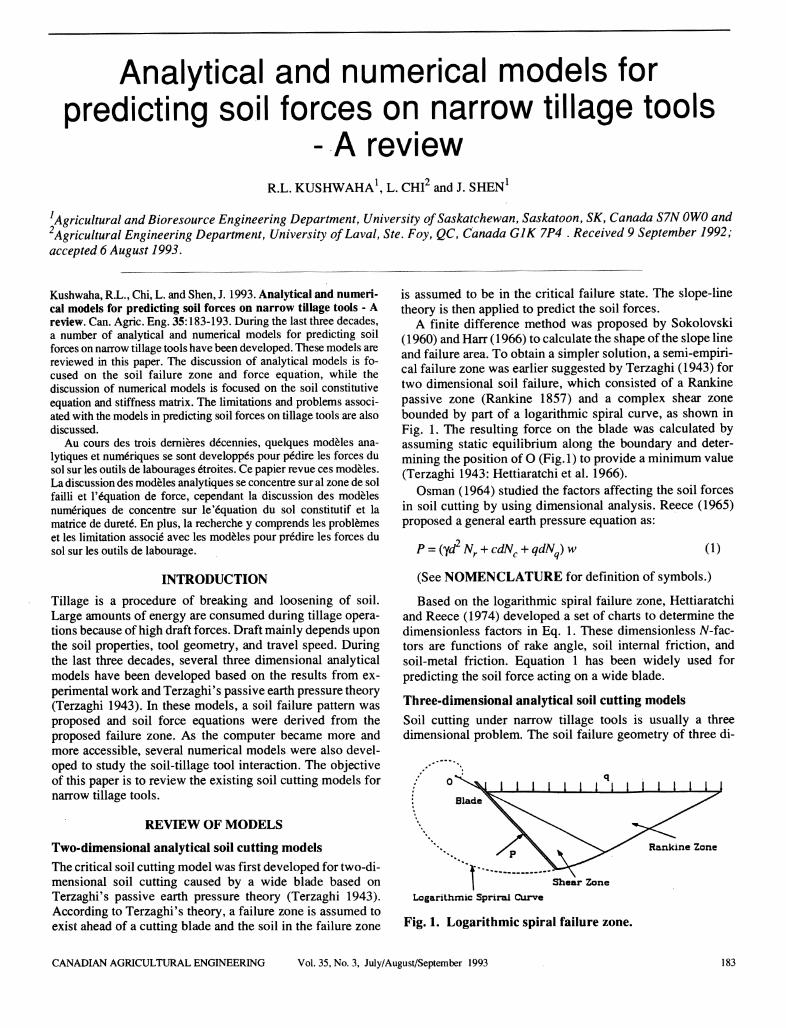
A finite difference method was proposed by Sokolovski(1960) and Harr (1966) to calculate the shape of the slope lineand failure area. To obtain a simpler solution, a semi-empirical failure zone was earlier suggested by Terzaghi (1943) fortwo dimensional soil failure, which consisted of a Rankinepassive zone (Rankine 1857) and a complex shear zonebounded by part of a logarithmic spiral curve, as shown inFig. 1. The resulting force on the blade was calculated byassuming static equilibrium along the boundary and determining the position of O (Fig. 1) to provide a minimum value(Terzaghi 1943: Hettiaratchi et al. 1966).
Osman (1964) studied the factors affecting the soil forcesin soil cutting by using dimensional analysis. Reece (1965)proposed a general earth pressure equation as:
P=(yd2 Nr +cdNc +qdN) w (1)
(See NOMENCLATURE for definition of symbols.)
Based on the logarithmic spiral failure zone, Hettiaratchiand Reece (1974) developed a set of charts to determine thedimensionless factors in Eq. 1. These dimensionless N-fac-tors are functions of rake angle, soil internal friction, andsoil-metal friction. Equation 1 has been widely used forpredicting the soil force acting on a wide blade.
Three-dimensional analytical soil cutting models
Soil cutting under narrow tillage tools is usually a threedimensional problem. The soil failure geometry of three di-
Shear Zone
Logarithmic Spriral Curve
Fig. 1. Logarithmic spiral failure zone.
Rankine Zone
CANADIAN AGRICULTURAL ENGINEERING Vol. 35, No. 3, July/August/September 1993 183

mensional soil cutting is more complicated than that of atwo-dimensional problem. Thereis no uniquesolution for thefailure pattern andtheshape of sliplines fora narrow tillagetool.Severaldifferentmodelshavebeenproposed to evaluatethe force required for soil failure.
Payne's model (1956) The first three-dimensional soil failure model was developed by Payne (1956) through the studyof the soil failure patterns obtained in a series of field andlaboratory tests. By observing the top surface soil heaveduring tillage, a failure zonewas proposed as shown in Fig.2. The failure zone included a triangular centre wedge, acentre crescent, and two side blocks (called wings of thecrescent). Further experiments showedthat the shape of thefailure zone changed with the geometry of tools such as rakeangle, depth, and width (Payne and Tanner 1959). Extensivetests were conducted by Payne and Tanner (1959) to studythe effects of the failure zone size and the rake angle on thedraft force. However, no equations were developedto evaluate the draft force for narrow tillage tools.
side blocks
center crescent
Fig. 2. Failure zone of Payne's model.
O'Callaghan-Farrelly model (1964) Following Payne'swork, O'Callaghan and Farrelly (1964) carried out a numberof field tests for three different soil conditions. At that time,Terzaghi's passive earth pressure theory was widely used incivil engineering to calculate safety factors in structural design. Therefore,O'Callaghan and Farrellyattemptedto adaptthis classical soil mechanics theory to develop an equation tocalculate the draft force during tillage operations. Based onthe field observations carried out with a vertical flat blade, asoil failure model was proposed as shown in Fig. 3. Themodel consisted of a forward failure above the critical depthand a horizontal failure under the critical depth (Fig. 3). Thecritical depth was equal to the tool width for a smooth bladeand half its width for a free surface with a normal restraint.For a shallow blade operating above the critical depth, a draftequation was developed by applying Terzaghi's method (Terzaghi 1943), which is given by:
H=w(cdNc+ydzNy) (2a)
For a deep blade, the force required for horizontal failurewas included as:
184
forward failure
horizontal failure
Fig. 3. Failurezone of the O'Callaghan-Farrellymodel.
H,=CW (d - kw) r 0 71 (I) tt tan/h, A [tan2 (- +ben tan* -!]+#_ (2b)
tan(|) v4 2
The comparison between results obtained from the proposed equation and the test data (O'Callaghan and Farrelly1964) were generally good except for a slight underprediction for the hardest soil tested. The O'Callaghan-FarrellyModel was developed prior to the well known Hettiaratchi-Reece two dimensional model. This model did not includethe effect of adhesion and external friction between the soiland the tool surface. During comparison, the gravity term inEq. 2 was also neglected because of the small masses of soil.In addition, the comparison was only conducted for a verticalblade.
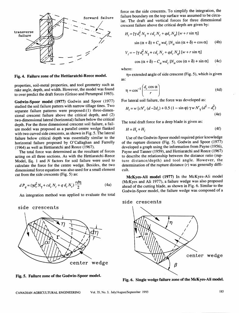
Hettiaratchi-Reece model (1967) Afterdeveloping the wellknown two dimensional soil failure equation (Eq. 1), Hettiaratchi and Reece (1967) proposed a three dimensional soilfailure model. In this model, the soil failure configurationwas divided into forward failure, ahead of the soil-tool interface, and transverse failure, the horizontal transversemovement of the soil away from the centre line of the interface, as shown in Fig. 4.
The total force on the tool was determined as a resultant ofthe forces from forward failure and transverse failure. Theforcecontributedby the forwardfailure was found simplybyusing the two dimensional soil failure equation (Eq. 1). Theforce requiredfor transversefailure was similar to theexpression derived by O'Callaghan and Farrelly (1964) except thata gravitational component was included. The total model canbe summarized by:
Pf= (yd2Ny +cdNc +qdNq) w
Pt=[lWe +±)2wNsy+cwdeNsc]Ka
(3a)
(3b)
H=Pjsin (a + 5) +Pt sin a +Cad cos a (3c)
V=Pfcos (a + 8) +Pt cos a +Cad (3d)
The Hettiaratchi-Reece model included the effects of soil
KUSHWAHA, CHI, and SHEN
transverse
failure
forward failure
//
/X
Fig. 4. Failure zone of the Hettiaratchi-Reece model.
properties, soil-metal properties, and tool geometry such asrake angle, depth, and width. However, themodel was foundtoover predict thedraft forces (Grisso andPerumpral 1985).
Godwin-Spoor model (1977) Godwin and Spoor (1977)studiedthe soil failure pattern with narrow tillage tines. Twoseparate failure patterns were proposed:(l) three-dimensional crescent failure above the critical depth, and (2)two-dimensional lateral (horizontal) failure below the criticaldepth. Forthe three dimensional crescent soil failure, a failure model was proposed as a parallel centre wedge flankedwith two curved side crescents, as shown in Fig. 5. The lateralfailure below critical depth was essentially similar to thehorizontal failure proposed by O'Callaghan and Farrelly(1964) as well as Hettiaratchi and Reece (1967).
The total force was determined as the resultant of forcesacting on all three sections. As with the Hettiaratchi-ReeceModel, Eq. 1 and N factors for soil failure were used tocalculate the force for the centre wedge. Besides, the twodimensionalforce equation was also used for a small elementcut from the side crescents (Fig. 5) as:
dP=(yd2Ny +cdcNc +qdcNc) rdr\(4a)
An integration method was applied to evaluate the total
side crescents
center wedge
Fig. 5. Failure zone of the Godwin-Spoor model.
force on the side crescents. To simplify the integration, thefailure boundary on thetop surface was assumed to be circular. The draft and vertical forces for three dimensionalcrescent failure above the critical depth are given by:
Ht=[yd2Ny+cdcNc +qdcNq][w +rsmT\]
sin (a +8)+ Ca wdc [Na sin (a + 8) + cos a] (4b)
Vt =-[yd*Ny+cdcNc +qdcNJ[w +rsmr\]
cos (a +8)- Ca wdc [Na cos (a + 8) + sin a] (4c)
where:
r|= extended angleof sidecrescent(Fig.5), whichis givenas:
^ccosaAT| =cos (4d)
For lateral soil failure, the force was developed as:
Ht =w[cN'c (d -2dc) +0.5 (1 - sin <p) ywN'y (d2 - d£)(4e)
The total draft force for a deep blade is given as:
(4f)
Use of the Godwin-Spoor model required prior knowledgeof the rupture distance (Fig. 5). Godwin and Spoor (1977)developed a graph usingthe information fromPayne(1956),Payne andTanner (1959), andHettiaratchi andReece (1967)to describe the relationship between the distance ratio (rupture distance/depth) and tool angle. However, thedetermination of the rupture distance (r) was generally difficult.
McKyes-Ali model (1977) In the McKyes-Ali model(McKyes and Ali 1977), a failure wedge was also proposedaheadof the cutting blade, as shown in Fig. 6. Similar to theGodwin-Spoor model, the failure wedge was composed of a
side crescents
center wedge
Fig. 6. Single wedge failure zone of the McKyes-Ali model.
CANADIANAGRICULTURALENGINEERING Vol. 35, No. 3, July/August/September 1993 185
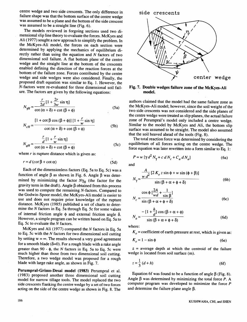
centre wedgeand two side crescents. The only difference infailure shape was that thebottom surface ofthecentre wedgewas assumed to be a plane and the bottom of the side crescentwas assumed to be a straight line (Fig. 6).
The models reviewed in forgoing sections used two dimensional sliplinetheory toevaluate theforces. McKyes andAli(1977) sought a new approach to simplify theproblem. Inthe McKyes-Ali model, the forces on each section weredetermined by applying the mechanics of equilibrium directly rather than using the equation and N factors of twodimensional soil failure. A flat bottom plane of the centrewedge and the straight line at the bottom of the crescentsenabled defining the direction of the reaction forces at thebottomof the failure zone. Forces contributed by the centrewedge and side wedges were also considered. Finally, theproposed draft equation was similar to Eq. 1. However, theN-factors were re-evaluated for three dimensional soil failure. The factors are given by the following equations:
AL„ =yH cot (a +5) +cot (P + <|>) (5a)
"cH= -
[1 + cot 0 cos (P+ <)>)] [1 + —sin ti]w
N„u = -
186
(5b)cot (a + 8) + cot (P + <|>)
J[l+^sinn]yqH cot(a +8) +cot(P +<|>) (5C)
where r is rupture distance which is given as:
r = d (cotp + cot a) (5d)
Each of the dimensionless factors (Eq. 5a to Eq. 5c) was afunction of angle p as shown in Fig. 6. Angle p was determined by minimizing the factor NyH (the factor for thegravity termin thedraft).AngleP obtained fromthisprocesswas used to compute the remaining N-factors. Compared tothe Godwin-Spoor model, the McKyes-Ali model is easier touse and does not require prior knowledge of the rupturedistance. McKyes (1985) published a set of charts to determine the N factors in Eq. 5a through Eq. 5c for some valuesof internal friction angle <|> and external friction angle 8.However, a simpleprogram canbe written basedon Eq.5a toEq. 5c to evaluate the N factors.
McKyes and Ali (1977) compared the N factors in Eq. 5ato Eq. 5c with the N factors for two dimensional soil cuttingby setting w = ©o. The results showeda very good agreementfor a smooth blade(8=0). For a roughbladewitha rakeanglegreater than 90 - <|), the N factors in Eq. 5a to Eq. 5c weremuch higher than those from two dimensional soil cutting.Therefore, a two wedge model was proposed for a roughblade with large rake angle, as shown in Fig. 7.
Perumpral-Grisso-Desai model (1983) Perumpral et al.(1983) proposed another three dimensional soil cuttingmodel for narrow tillage tools. The model replaced the twoside crescents flanking the centre wedge by a set of two forcesacting on the side of the centre wedge as shown in Fig. 8. The
side crescents
center wedge
Fig. 7. Doublewedges failure zone of the McKyes-Alimodel.
authors claimed that the model had the same failure zone asthe McKyes-Ali model; however, sincethe soil weightof thetwo side crescents wasnot considered and the sideplanes ofthe centre wedge were treated as slip planes, the actual failurezone of Perumpral's model only included a centre wedge.Similar to the model by McKyes and Ali, the bottom slipsurface was assumed to be straight. The model also assumedthat the soil heaved ahead of the tools (Fig. 8).
Thetotalreaction forcewasdetermined by considering theequilibrium of all forces acting on the centre wedge. Theforce equation was later rewritten intoa form similar to Eq. 1:
P=w[yd2NTy+cdNc +CadNa]and
Ny = wtf[2 KQ z sin § + w sin (<|) + P)]
sin (P + a + <|) + 8)
cos § [— + -]N= VW sinpJc sin (p + a + (|) + 8)
-[l+-]cos(P + cc + <|>)N= -
a sin(p + oc + (|) + 8)where:
KQ = coefficientof earth pressure at rest, which is given as:
K0 = 1- sin (|> (6e)
z = average depth at which the centroid of the failurewedge is located from soil surface (m).
z=|(d+A)
(6a)
(6b)
(6c)
(6d)
(6f)
Equation 6f was found to be a function of angle P (Fig. 8).Angle p was determined by minimizing the total force P. Acomputer program was developed to minimize the force Pand determine the failure plane angle p.
KUSHWAHA, CHI, and SHEN
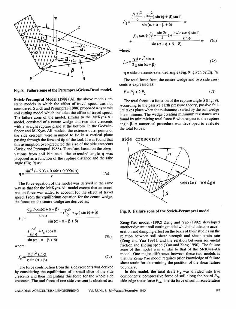
Fig. 8. Failure zone of the Perumpral-Grisso-Desai model.
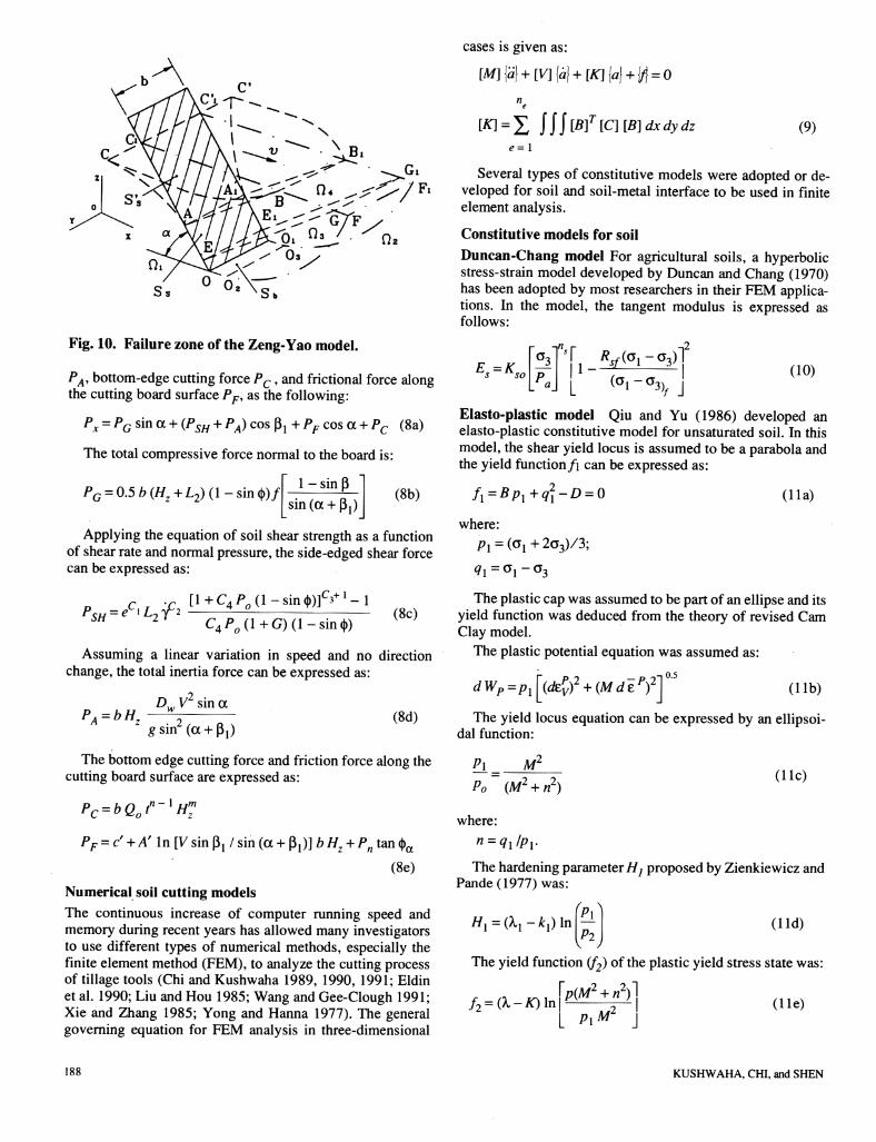
Swick-Perumpral Model (1988) All the above models arestatic models in which the effect of travel speed was notconsidered. Swick and Perumpral (1988) proposed a dynamicsoil cutting model which included the effect of travel speed.The failure zone of the model, similar to the McKyes-Alimodel, consisted of a centre wedge and two side crescentswith a straight rupture plane at the bottom. In the Godwin-Spoorand McKyes-Ali models, the extreme outer points ofthe side crescent were assumed to lie in a vertical planepassing throughthe forward tip of the tool. It was found thatthis assumption over-predicted the size of the side crescents(Swickand Perumpral 1988).Therefore, based on the observations from soil bin tests, the extended angle r| wasproposed as a function of the rupture distance and the rakeangle (Fig. 9) as:
sin"1 (- 6.03 + 0.46r+ 0.0904 a)(7a)
The force equation of the model was derived in the sameway as that for the McKyes-Ali model except that an acceleration force was added to account for the effect of travelspeed. From the equilibrium equation for the centre wedge,the forces on the centre wedge are derived as:
CflJcos(oc + (i) +P) ydr . . .. ftx— : +(-Lr + <?r)sin((t> + p)
sin a ^^1 = sin (a + <|> + P + 8)
Ct-t +/„/) cos <|>sinQ
sin (a + <|> + P + 8)
where:
ydv sin a
/a/~gsin(a +P)
(7b)
(7c)
The force contribution from the side crescents was derived
by considering the equilibrium of a small slice of the sidecrescents and then integrating this force for the whole sidecrescents. The tool force of one side crescent is obtained as:
2 ?(Y^L +a£.)sintt +p)sinl1
sin (a + ty + p + 8)p2=- w
,ti sin2ri c drcoscb sinr|
_j_ w
sin (a + ty + p + 8)
where:
fa2~ydrv sin a
2 g sin (a + p)
r\ = sidecrescents extendedangle (Fig.9) givenby Eq. 7a.
The total force from the centre wedge and two side crescents is expressed as:
P = P{ + 2P2
(7d)
(7e)
(7f)
The total force is a function of the rupture angle P (Fig. 9).According to the passive earth pressure theory, passive failure takesplace when the resistanceexertedby the soil wedgeis a minimum. The wedge creating minimum resistance wasfound by minimizing total force P with respect to the ruptureangle p. A numerical procedure was developed to evaluatethe total forces.
side crescents
center wedge
Fig. 9. Failure zone of the Swick-Perumpral model.
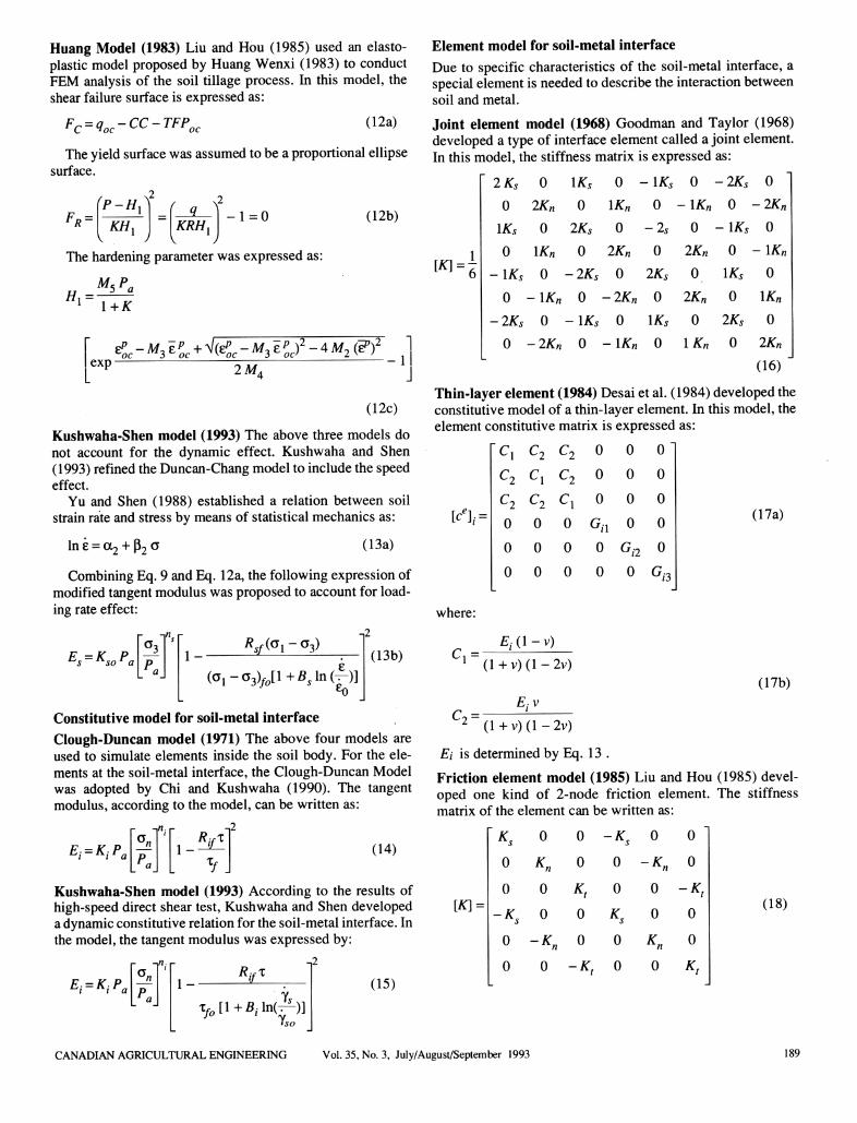
Zeng-Yao model (1992) Zeng and Yao (1992) developedanother dynamic soil cutting model which included the acceleration and damping effect on the basis of their studies on therelation between soil shear strength and shear strain rate(Zeng and Yao 1991), and the relation between soil-metalfriction and sliding speed (Yao and Zeng 1990). The failurezone of the model was similar to that of the McKyes-Alimodel. One major difference between these two models isthat the Zeng-Yao model requires prior knowledge of failureshear strain for determining the position of the shear failureboundary.
In this model, the total draft Px was divided into fivecomponents: compressive force of soil along the board PG,side-edgeshear force PSH, inertia force of soil in acceleration
CANADIAN AGRICULTURAL ENGINEERING Vol. 35, No. 3, July/August/September 1993 187
X^Z^ G7F y
Fig. 10. Failure zone of the Zeng-Yao model.
PA% bottom-edge cutting force Pc, and frictional force alongthe cutting boardsurface PF, as the following:
Px = PG sin a + (PSH + PA) cos $x +PF cos a +Pc (8a)
The total compressive force normal to the board is:
1 - sin PPG = 0.5b(Hz+L2)(l-sm<b)f
sin (a + Pj)(8b)
Applying the equation of soil shear strength as a functionof shear rate and normal pressure, the side-edgedshear forcecan be expressed as:
PSH =eC,L2;f2C,+ l[l+C4P0(l-sinWf'3+l-l
C4P0(l+G)(l-sin®(8c)
Assuming a linear variation in speed and no directionchange, the total inertia force can be expressed as:
PA = bHzDw VL sina
gsin2(a +p1)(8d)
The bottom edge cutting force and friction force along thecutting board surface are expressed as:
Pc =bQ0tn-xHmz
PF = c +A' In [V sin $Y / sin(a + Pj)] bHz +Pn tan (^
(8e)
Numerical soil cutting models
The continuous increase of computer running speed andmemory during recent years has allowed many investigatorsto use different types of numerical methods, especially thefinite element method (FEM), to analyze the cutting processof tillage tools (Chi and Kushwaha 1989, 1990, 1991; Eldinet al. 1990; Liu and Hou 1985; Wang and Gee-Clough 1991;Xie and Zhang 1985; Yong and Hanna 1977). The generalgoverning equation for FEM analysis in three-dimensional
188
cases is given as:
[Af]{a}+[V]{a}+[K}{a} +\/\ =0n
e
[*] =X jjj&f[C][B]dxdydz (9)
Several types of constitutive models were adopted or developed for soil and soil-metal interface to be used in finiteelement analysis.
Constitutive models for soil
Duncan-Chang model For agricultural soils, a hyperbolicstress-strain model developed by Duncan and Chang (1970)has been adopted by most researchers in their FEM applications. In the model, the tangent modulus is expressed asfollows:
Es = Kso "jj vgi-g3>fL <°i-*3VJ
(10)
Elasto-plastic model Qiu and Yu (1986) developed anelasto-plastic constitutive model for unsaturated soil. In thismodel, the shear yield locus is assumed to be a parabola andthe yield functionf\ can be expressed as:
f1=Bpl+q21-D =0 (11a)
where:
p, = (0!+2o3)/3;
<?l=ai-a3
The plastic cap was assumed to be part of an ellipse and itsyield function was deduced from the theory of revised CamClay model.
The plastic potential equation was assumed as:
dWP=p^(dzpv)2 +(Mdtpf^ (lib)
The yield locus equation can be expressed by an ellipsoidal function:
P± =Po (Mz + n2)
where:
n = ql/pl.
The hardening parameter//; proposed by Zienkiewicz andPande (1977) was:
M£
//, =(^ - jfcj) In
(He)
yP2J(Hd)
The yield function (f2) of the plastic yield stress state was:
f2=(X-K)lnp(M2 +n2)
P\ML(lie)
KUSHWAHA, CHI, and SHEN
Huang Model (1983) Liu and Hou (1985) used an elasto-plastic model proposedby Huang Wenxi (1983) to conductFEM analysis of the soil tillage process. In this model, theshear failure surface is expressed as:
Fr = q-CC-TFPn (12a)
Theyieldsurface wasassumed to be a proportional ellipsesurface.
Fr =rP-Hl
KH, KRH,-1=0 (12b)
The hardening parameter was expressed as:
//i =Mspal+K
zPoc-M3zpoc +Mc-M3ZPof-*M2^ yexp 2^- -1
(12c)
Kushwaha-Shen model (1993) The above three models donot account for the dynamic effect. Kushwaha and Shen(1993) refined the Duncan-Chang model to include the speedeffect.
Yu and Shen (1988) established a relation between soilstrain rate and stress by means of statistical mechanics as:
Ine = a2 + p2 a (13a)
Combining Eq. 9 and Eq. 12a, the following expression ofmodified tangent modulus was proposed to account for loading rate effect:
Es~ Kso Pa 1-Rsf^\~^)
-2
fc0
(13b)
Constitutive model for soil-metal interface
Clough-Duncan model (1971) The above four models areused to simulate elements inside the soil body. For the elements at the soil-metal interface, the Clough-Duncan Modelwas adopted by Chi and Kushwaha (1990). The tangentmodulus, according to the model, can be written as:
Ei= KtPa 1-RtIx
-.2
X/
(14)
Kushwaha-Shen model (1993) According to the results ofhigh-speed direct shear test, Kushwaha and Shen developeda dynamic constitutive relation for the soil-metal interface. Inthe model, the tangent modulus was expressed by:
Ei= KiPa 1-M
T/o[l+/?,.ln(^)]*so
(15)
Element model for soil-metal interface
Due to specific characteristics of the soil-metal interface, aspecialelement is needed to describe the interactionbetweensoil and metal.
Joint element model (1968) Goodman and Taylor (1968)developed a type of interfaceelement called a joint element.In this model, the stiffness matrix is expressed as:
[K]=-
2KS 0 \KS 0 -IKS 0 -2KS 0
0 2Kn 0 lKn 0 -lKn 0 -2K„
IKS 0 2KS 0 -2S 0 -IKs 0
0 \K„ 0 2Kn 0 2K„ 0 -\K„
-IKS 0 -2KS 0 2KS 0 IKs 0
0 -\Kn 0 -2K„ 0 2Kn 0 \Kn
-2KS 0 -IKs 0 IKs 0 2KS 0
0 -2K„ 0 -\Kn 0 \Kn 0 2Kn
(16)
Thin-layer element (1984) Desai et al. (1984) developed theconstitutive model of a thin-layer element. In this model, theelement constitutive matrix is expressed as:
[cV
-1 c2 c2 0 0 0
c2 cx c2 0 0 0
c2 c2 cx 0 0 0
0 0 0 Gn 0 0
0 0 0 0 G,2 0
0 0 0 0 0 G,
(17a)
where:
1 (l+v)(l-2v)
£,.(l-v)
£,.vc =
2 (l+v)(l-2v)
/3
(17b)
Ei is determined by Eq. 13 .
Friction element model (1985) Liu and Hou (1985) developed one kind of 2-node friction element. The stiffnessmatrix of the element can be written as:
[K] =
«s 0 0 "*, 0 0
0 *» 0 0 ~*n 0
0 0 K, 0 0 -A
Ks 0 0 «s 0 0
0 -*„ 0 0 *n 0
0 0 -K, 0 0 K,
(18)
CANADIAN AGRICULTURAL ENGINEERING Vol. 35, No. 3, July/August/September 1993 189
DISCUSSION
In all analytical models except the Pane's model, soil forceequations were developed to calculate draft and verticalforce. These equations are generally simple to use. The values of dimensionless factors in the O'Callaghan-Farrelly,Hettiaratchi-Reece and Godwin-Spoor models can be foundin the charts developed by Hettiaratchi and Reece (1974).However, the Godwin-Spoor modelneedsa priorknowledgeof rupturedistance r. McKyes (1985)alsodeveloped a seriesof charts to evaluate the N-factors in their model. For thePerumpral-Grisso-Desai modelandSwick-Perumpral model,a simple program can be written to determine the ruptureangle by minimizing the total tool force. For the Zeng-Yaomodel, it requires prior knowledge of the failure shear strainfor determining the shear failure boundary.
The analytical models generally performed well, basedupon the model verification conducted individually by theirown authors. Comparisons between some models were alsoconducted by some researchers. The over-prediction of draftforces of the Hettiaratchi-Reece model was reported in somecases (Grisso and Perumpral 1985). The over-prediction ofthe Hettiaratchi-Reece model was possibly caused by theassumption of the forward failure and transverse failure at thesame time in which the effect of the centre wedge might beconsidered twice. The Godwin-Spoor, McKyes-Ali, and Perumpral-Grisso-Desai models generally gave an accurateprediction to the forces. However, since the Perumpral-Grisso-Desai model ignored the soil weight of the sidecrescents, the predicted forces were slightly lower than thosepredicted by the Godwin-Spoor model and the McKyes-Alimodel for a narrow blade (Grisso and Perumpral 1985).TheGodwin-Spoor model and the McKyes-Ali model over-predicted the disturbed area (Swick and Perumpral 1988).
In all analytical models, a failure zone was proposed.Some simplification of the failure zone was made in order todevelop the force equation, such as circular side crescents(the Godwin-Spoor model, the McKyes-Ali model, the Perumpral-Grisso-Desai model, and the Swick-Perumpralmodel) and straight bottom rupture plane (the McKyes-Alimodel, the Perumpral-Grisso-Desai model, and the Swick-Perumpral model). The prediction accuracy of forces isdirectly related to the accuracy of the proposed failure zone.In addition, the tool shape, such as sweep and curved blades,may affect the shape and size of the soil failure zone. Theanalytical models are not capable of considering these effects. Therefore, the models can not provide enoughinformationto guide the optimum design of a tillage tool.
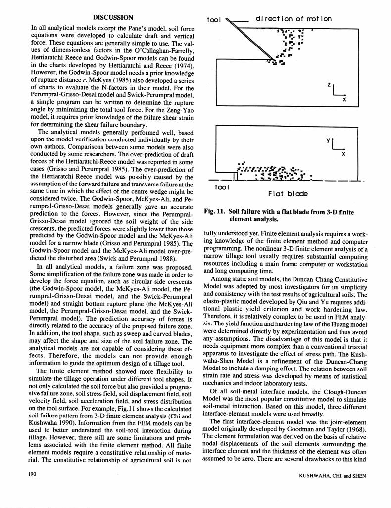
The finite element method showed more flexibility tosimulate the tillage operation under different tool shapes. Itnot only calculatedthe soil force but also provideda progressive failure zone, soil stress field, soil displacement field, soilvelocity field, soil acceleration field, and stress distributionon the tool surface. For example, Fig.l 1 shows the calculatedsoil failure pattern from 3-D finite element analysis (Chi andKushwaha 1990). Information from the FEM models can beused to better understand the soil-tool interaction duringtillage. However, there still are some limitations and problems associated with the finite element method. All finiteelement models require a constitutive relationship of material. The constitutive relationship of agricultural soil is not
190
tool di rect ion of mot ion
'!_
toolFlat blade
Fig. 11. Soil failure with a flat blade from 3-D finiteelement analysis.
fullyunderstood yet.Finiteelementanalysisrequiresa working knowledge of the finite element method and computerprogramming. The nonlinear 3-Dfinite elementanalysis of anarrow tillage tool usually requires substantial computingresources including a main frame computer or workstationand long computing time.
Amongstatic soil models, the Duncan-Chang ConstitutiveModel was adopted by most investigators for its simplicityand consistencywith the test results of agricultural soils.Theelasto-plastic model developed by Qiu and Yu requires additional plastic yield criterion and work hardening law.Therefore, it is relatively complex to be used in FEM analysis.Theyield function andhardening lawoftheHuang modelwere determined directly by experimentation and thus avoidany assumptions. The disadvantage of this model is that itneeds equipment more complex than a conventional triaxialapparatus to investigate the effect of stress path. The Kushwaha-Shen Model is a refinement of the Duncan-ChangModel to include a damping effect. The relation between soilstrain rate and stress was developed by means of statisticalmechanics and indoor laboratory tests.
Of all soil-metal interface models, the Clough-DuncanModel was the most popular constitutive model to simulatesoil-metal interaction. Based on this model, three differentinterface-elementmodels were used broadly.
The first interface-element model was the joint-elementmodel originally developed by Goodman and Taylor (1968).The element formulation was derived on the basis of relativenodal displacements of the soil elements surrounding theinterface element and the thickness of the element was oftenassumed to be zero. There are several drawbacks to this kind
KUSHWAHA, CHI, and SHEN
of element. Joint element can only describe the relation between shear stress and relative displacement. When shearstress exceeds the limit of traction criterion, either shear
stress x can be reduced or normal stress o can be increased tomeet the need of the friction criterion; thus, a different solution can be obtained, i.e. the solution is uncertain. In addition,interpenetration of nodes may occur after elements are subjected to compressive forces.
The second interface-element model was that of Desai et
al. (1984) who designed a kind of thin layer element. Theform of the constitutive matrix and the expression of tangential modulus for this element are very similar to those of soilelements with the Duncan-Chang Model. As a result, it iseasy to develop a computer program of thin-layer elements inreference to the program of soil elements with the Duncan-Chang model.
The third interface-element model is that of Liu and Hou
(1985) who developed one kind of 2-node finite element. Themain advantage of this element is the simplicity of the element form. If Kn is specified as a very large value, theinterpenetration of nodes can be avoided. Besides, it is easyto regenerate the elements after large displacement occurred.The disadvantage of the friction element is that the internalstress of friction element has to be determined by the summation of internal stresses of surrounding elements. This causesmany extra calculations.
SUMMARY AND CONCLUSIONS
Several analytical models were reviewed in this paper. Allthe traditional models proposed a failure zone and derivedequations based upon the proposed failure zone. The analytical models are simple to use. However, these models can notinclude the effects of sweep and curved blades. Therefore,application of these models is limited for optimum design ofa tillage tool.
The finite element method has the capability of simulatingdifferent tool shapes and dynamic effect of travel speed. Thefinite element method also provided additional informationsuch as: force, soil stress, soil displacement, etc. This information could help to understand the soil-tool interactionduring tillage. However, this method is time-consuming indata preprocessing , programming, and calculations.
At the present time, the application of finite element analysis is limited by lack of an accurate soil constitutive modelwhich can account for the nonlinearity, elasto-plastic deformation, anisotropy, and dynamic properties of agriculturalsoils.
REFERENCES
Chi, L. and R.L. Kushwaha. 1989. Finite element analysis offorces on a plane soil blade. Canadian Agricultural Engineering 31(2):135-140.
Chi, L. and R.L. Kushwaha. 1990. A nonlinear 3-D finiteelement analysis of soil failure for tillage tools. JournalofTerramechanics 27(4):343-366.
Chi, L. and R.L. Kushwaha. 1991. Finite element analysis offorces on two shapes of tillage tools. Canadian Agricultural Engineering 33(1): 39-45.
Clough, G.W. and J.M. Duncan. 1971. Finite element analysis of retaining wall behavior. Journal of the SoilMechanics and Foundation Division, American Societyof Civil Engineers 97:1657-1673.
Desai, C.S., M.M. Zaman, J.G. Lightner and H.J. Siriwar-dane. 1984. Thin layer element for interface and joints.International Journal ofNumerical Analysis Method Ge-omech. 16(l):19-43.
Duncan, J.M. and C.Y. Chang. 1970. Nonlinear analysis ofstress and strain in soils. Journal of the Soil Mechanicsand Foundation Division, American Society of Civil Engineers 96:1629-1653.
Eldin, A.M.Z., K.C. Watts, S.M. Younis and M. Shaibon.1990. Development of a two dimensional finite elementmodel of soil-tool interaction. ASAE Paper No. 90-1544.St. Joseph, MI: ASAE.
Godwin, R. J. and G. Spoor. 1977. Soil failure with narrowtines. Journal of Agricultural Engineering Research22(4):213-228.
Goodman, R.E. and R.L. Taylor. 1968. A model for themechanics of jointed rock. Journal of the Soil Mechanicsand Foundation Division, American Society of Civil Engineers 94:637-660.
Grisso, R.D. and J.V. Perumpral. 1985. Review of model forpredicting performance of narrow tillage tool. Transactions of the ASAE 28(4): 1062-1067.
Harr, M.E. 1966. Foundation ofTheoretical Soil Mechanics.New York, NY: McGraw-Hill Book Company.
Hettiaratchi, D.R.P. and A.R. Reece. 1967. Symmetricalthree-dimensional soil failure. Journal of Terrame-chanics 4(3):45-67.
Hettiaratchi, D.R.P. and A.R. Reece. 1974. The calculation ofpassive soil resistance. Geotechnique 24(3):280-310.
Hettiaratchi, D.R.P., B.D. Whitney and A.R. Reece. 1966.The calculation of passive pressure in two-dimensionalsoil failure. Journal of Agricultural Engineering Research 11(2):89-107.
Huang, W. 1986. Engineering Properties of Soils (inChinese). Bejing, China: Hydrological and ElectricPower Publishing House.
Kushwaha, R.L. and J. Shen. 1993. Three-dimensional finiteelement analysis of high-speed tillage. In Proceedings of14th Canadian Congress of Applied Mechanics, 2:691-692.
Liu,Y. and Z.M. Hou. 1985. Three dimensional nonlinearfinite element analysis of soil cutting by narrow blades.In Proceedings of the International Conference on SoilDynamics, 2:412-427. Auburn, AL.
McKyes, E. 1985. Soil Cutting and Tillage. New York, NY:Elsevier Science Publishing Company.
McKyes, E. and O.S. Ali. 1977. The cutting of soil by anarrow blade. Journal ofTerramechanics 14(2):43-58.
O'Callaghan J.R. and K.M. Farrelly. 1964. Cleavage of soilby tined implements. Journal of Agricultural Engineering Research 9:259-270.
CANADIAN AGRICULTURAL ENGINEERING Vol. 35, No. 3, July/August/September 1993 191
Osman, M.S. 1964. The mechanics of soil cutting blades.Journal of Agricultural Engineering Research 9(4):313-328.
Payne, P.C.J. 1956. The relationship between the mechanicalproperties of soil and the performance of simple cultivation implements. Journal of Agricultural EngineeringResearch l(l):23-50.
Payne, P.C.J, and D.W. Tanner. 1959. The relationship between rake angle and the performance of simplecultivation implements. Journal of Agricultural Engineering Research 4(4):312-325.
Perumpral, J.V., R.D. Grisso and C.S. Desai. 1983. A soil-tool model based on limit equilibrium analysis.Transactions of the ASAE 26(4):991-995.
Qiu, L. and Q. Yu. 1988. Investigation of unsaturated soilstress-strainrelations. In Proceedings ofthe2nd Asia-Pacific Conference of the International Societyfor TerrainVehicle Systems, 13-22. Bangkok, Thailand.
Rankine, W.J.M. 1857. On the stability of loose earth. Philosophical Transaction of the Royal Society 147:9-27.
Reece, A.R. 1965. The fundamental equation of earth-moving mechanics. In Symposium on Earth-MovingMachinery, Proceedings ofthe Institution of MechanicalEngineers, 179(3F): 16-22.
Sokolovski, V.V. 1960. The Static of Soil Media. London,U.K.: Butterworths.
Swick, W.C. andJ.V. Perumpral. 1988.A model for predicting soil-tool interaction. Journal of Terramechanics25(l):43-56.
Terzaghi, K. 1943. Theoretical Soil Mechanics. New York,NY: Chapman and Hill Ld., John Wiley and Sons Inc.
Wang, J. and D. Gee-Clough. 1991. Deformation and failurein wet clay soil, II. Simulation of tine soil cutting. IAMCConference, Beijing, China, 2-219-2-226.
Xie, X.M. and D.J. Zhang. 1985. An approach to 3-D nonlinear FEM simulative method for investigation of soil-tooldynamic system. In Proceedings of the InternationalConference on Soil Dynamics, 2:322-327. Auburn, AL.
Yao, Y. and D. Zeng. 1990. Investigation of the relationshipbetween soil metal friction and sliding speed. Journal ofTerramechanics 27(4):283-290.
Yong, R.N. and A.W. Hanna. 1977. Finite element analysisof plane soil cutting. Journal of Terramechanics14(3):103-125.
Yu, Q. and J. Shen. 1988. Research on the rheological properties of wet soils (Part I): Flow characteristics. InProceedings of 2nd Asia-Pacific Conference of The International Society for Terrain Vehicle Systems, 23-40.
Zeng, D. and Y. Yao. 1991. Investigation on the relationshipbetween soil shear strength and shear strain rate. JournalofTerramechanics 28(1):1-10.
Zeng, D. and Y. Yao. 1992. A dynamic model for soil cuttingby blade and tine. Journal ofTerramechanics 29(3):317-328.
Zienkiewicz, O.C. and G.N. Pande. 1977. Some useful forms
192
of isotropic yield surfaces for soil, and rock mechanics. InFinite Elements in Geomechanics, G. Gudehus, ed., 171-190. Chichester, NY: Wiley.
NOMENCLATURE
{a} Displacement vector (m){a} Velocity vector (m/s){a} Acceleration vector (m/s2)A Side area of failure wedge (m2)b Cutting width (m)B Coefficient of Eq. 11aBt Coefficient of Eq. 15Bs Coefficient of Eq. 13b[B] Element strain matrix
c Soil cohesion (Pa)
ca Soil-metal adhesion (Pa)
C, A', §a Soil-metal dynamic friction parameters(Yao and Zeng 1990)
Cx, C2, C3,C4 Soil dynamic shearstrength parameters(Zeng and Yao 1991)
CC Test parameter of Eq. 12a[C] Element constitutive matrix
d Tool operating depth (m)dc Criticaldepth (m)de Effective depth of transverse failure (m)D Coefficient of Eq. 11aDw Soil wet bulk density (kg/m3)Et Tangent modulus of interface (Pa)Es Tangent modulus of soil (Pa){/} Force vector (AT)
fal Acceleration force on center wedge (AOfa2 Acceleration force on side crescent (AOg Gravitational constant (9.81 m/s2)h Height of soil heave in front of the tool at failure (m)H Draft on tillage tool (AT)Hx Hardening parameterHd Draft for deep blade (AOH{ Draft from lateral soil failure (AOHs Draft for shallow blade (A0Ht Draft above criticaldepth (AOHz Cutting depth (m)k Ratio of critical depth to widthkx Test constant of Eq. 11.K, R, M2,M3,M4,M5 Parameters determined from the
experiment for Eq. 12Ka Tine "inclination factor"Kt Coefficient of Clough-Duncan Eq. 14Kn Normal stiffness (N/m)K0 Coefficient of earth pressure at restKs, £,Shear stiffness (N/m)Kso Coefficient of Duncan-Chang Eq. 10[K\ Stiffness matrix
M Coefficient of Eq. lib[M] Mass matrix (kg)
KUSHWAHA, CHI, and SHEN
ne Total number of elements in structuren{ Coefficient ofClough-Duncan Eq. 14ns Coefficient ofDuncan-Chang Eq. 10
Nr Nc, Nr Na> NsT Nsc> ^YH> *cH' NqW N'T N'cDimensionless factors
Reference size of yield locus (Pa)Total force on tillage tool (N)Atmosphere pressure (Pa)Total initial force (N)
Bottom edge cutting force (N)Force from forward failure (N)
Friction along cutting board surface (N)Total compressive force normal to the board (N)Force from transverse failure (N)
Total draft (N)
Octahedral normal stress (Pa)
Side-edged shear force (N)Surcharge pressure on surface (Pa)Octahedral shear stress (Pa)
Rupture distance (m)Failure ratio at soil-metal interface
Failure ratio of soil
Test parameters of Eq. 12aDamping matrixTravel speed of tool (m/s)Vertical force on tillage tool (AOVertical force from three dimensional soil failure
above critical depth (AOTool width (m)
Plastic potential (Pa)Averagedepth where the centroid of failure wedgeis located from soil surface (m)
Pop
pn
7
FoePSHq
r
R*fTF
[V]v
V
W
w„
a
a2
P
P2P.
Y
'SO
8
e
Rake angle
Coefficient of Eq. 13a
Failure plane angle
Coefficient of Eq. 13a
Angle of absolute velocity of the soil slice with theground surface
Unit weight of soil (N/m )
Actual shear strain rate (s~ )
Maximum shear strain rate at direct shear box
External friction angle
Actual strain rate in soil (s" )
Maximum strain rate at triaxial apparatus
eocp Plastic component of octahedral normal strain8 cp Plastic component of octahedral shear strainde p Plastic shear strain
dEj) Plasticvolume strainX! Testconstant of Eq. 11dv Poisson ratio
a Stress or strength (Pa)
Gn Normal stress at interface (Pa)cx Major principal stressin soil (Pa)G3 Minor principal stress in soil (Pa)(oj-o3)f Shear strength (Pa)(G1-G3)y0 Shear strength obtained from conventional
triaxial test (Pa)
x Actual shear stress (Pa)
T/Shear strength at interface (Pa)
<|) Internal soil friction angle
CANADIAN AGRICULTURAL ENGINEERING Vol. 35, No. 3, July/August/September 1993 193