Embed Size (px)
Citation preview
Mechanics and Mechanical Engineering
Vol. 17, No. 2 (2013) 167–176
c⃝ Lodz University of Technology
Analytical and Experimental Studies of Stabilityof Cylindrical Shells with a Cut–Out
Piotr Stasiewicz
Institute of Applied MechanicsPoznan University of Technology
Jana Pawa II 24, 60-965 Poznan, [email protected]
Received (11 March 2013)
Revised (16 April 2013)
Accepted (20 May 2013)
Thin–walled structure, by its nature, is subjected to loss of stability. In addition, theshell has a cutout, which reduces the critical load. The aim of this study is to determinecritical stress of the shell under pure bending. The goal was achieved in two ways:experimentally and analytically. Experimental studies were carried out on a speciallydesigned test bench with the use of a resistive strain gauge. In the analytical solutionthe form of buckled shell was assumed, and then Bubnov–Galerkin method was applied.
Keywords: Cylindrical shell, buckling, cut–out.
1. Introduction
Analysis of thin–walled structures must not be confined to the strength condition.Checking their stability is particularly important too. There is an extensive litera-ture devoted to stability of the structure. An example of a monographic approachis the work of Volmir [1]. However, significant part of publications concerns idealshells. Real structures can have many types of imperfections. The work of Staat [2]and Aghajari et al [3] are devoted to the studies on stability of cylindrical shells ofvariable thickness subjected to uniform external pressure. Ahn et al [4] presentedcomparison of the results of numerical and experimental investigation of strength ofa bending pipe with local reduction of its thickness. Stability studies of an axiallycompressed shell with cutout or crack was described by Limam Jullien [5], Vaziriand Estekanchi [6] and Schenk and Schueller [7]. Similar studies are presented inthe works of Meng–Kao Yeh and others [5] and Alashti and others [3], but in thosepublications a shell is subjected to bending. Wilde and others [11] presented ananalytical solution of stability of cylindrical panel subjected to compression, withthree edges simply supported and one edge free.
168 Stasiewicz, P.
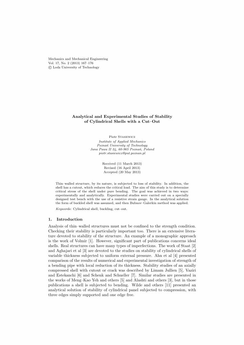
The aim of the present paper is to investigate buckling of a damaged thin–walledcylindrical shell under pure bending (Fig.1). Imperfection of the considered shellhas a shape of a circular cut–out placed on the upper (compressed) generatrix of thecylinder. The paper consists of two main parts: the first one includes experimentalinvestigation, while the second is devoted to analytical solution of the problem.
a L a2R
t
F
D
Fs2
R
Figure 1 Cylindrical shell with cut–out in pure bending
2. Experimental Investigation
A special test stand (Fig. 2) was designed and built in order to carry out experi-mental investigations of the buckling process in cylindrical shells in pure bending.The cylindrical shell is pivoted on its ends making use of rigid grip. The load isapplied by the testing machine through the beam in a form of two forces actingon these grips. In result pure bending occurs between them, with bending momentvalue 0.5Fa. Strain gauges are located near the cut–out. During the test the testingmachine induces the load F the value of which is registered as a function of time.Similarly, indications of the strain gauges, are processed by a multichannel univer-sal amplifier. Moreover, the rotation angle of the shell end was measured. Thedimensions of the shells were as follows: L = 600mm, a = 150mm, R = 100mm.The shells made of steel, aluminium alloy and brass were tested. The mechanicalproperties and thicknesses of the shells are given in Tab. 1.

Analytical and Experimental Studies of Stability ... 169
Figure 2 Test stand with the shell
Figure 3 Strain as a function of load
170 Stasiewicz, P.
Table 1 Mechanical properties and thickness of shells
Material Rp0,2 [MPa] Rm [MPa] A [%] t [mm]Steel 226.0 346.3 35.5 0.5Aluminium alloy 128.0 128.5 0.25 0.5Brass 289.2 393.7 31.1 0.6
The test stand was also equipped with eight–channel strain gauge HBM Spider8amplifier with computer data acquisition system Catman. During the study twostrain gauges placed near the cut–out and three inductive sensors placed in thecommon base were used. An example of the relationship between the load anddeformation is shown in Fig. 3. As critical load is assumed the value of forcecorresponding to the first extreme of strain (Fig. 3).
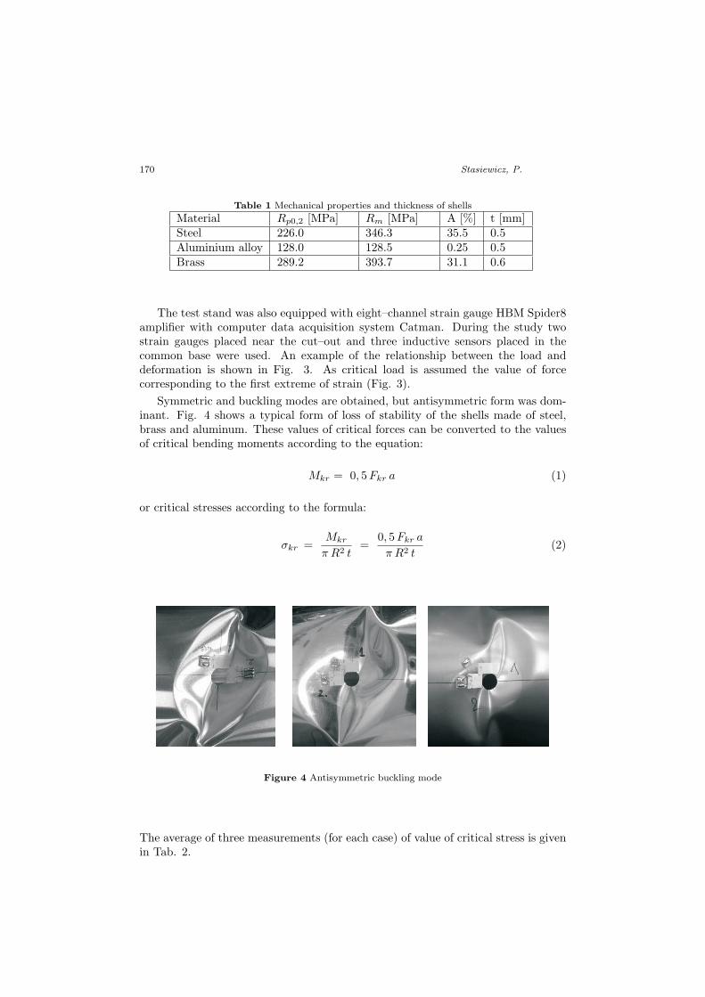
Symmetric and buckling modes are obtained, but antisymmetric form was dom-inant. Fig. 4 shows a typical form of loss of stability of the shells made of steel,brass and aluminum. These values of critical forces can be converted to the valuesof critical bending moments according to the equation:
Mkr = 0, 5Fkr a (1)
or critical stresses according to the formula:
σkr =Mkr
π R2 t=
0, 5Fkr a
π R2 t(2)
Figure 4 Antisymmetric buckling mode
The average of three measurements (for each case) of value of critical stress is givenin Tab. 2.
Analytical and Experimental Studies of Stability ... 171
Table 2 The critical stress of shell with circular cut–out
R0 [mm]Critical stress σkr MPasteel brass aluminium
514
183.3114.6
203.3117.4
96.958.3
3. Analytical Solution
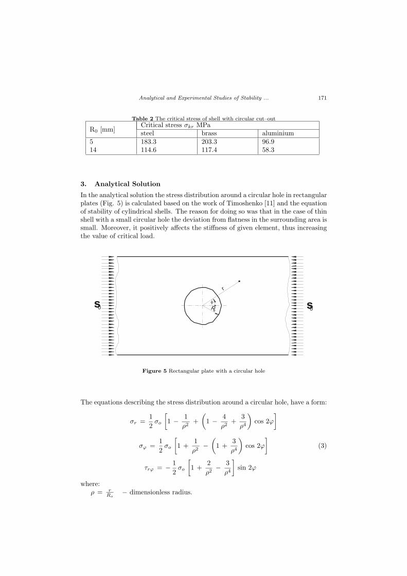
In the analytical solution the stress distribution around a circular hole in rectangularplates (Fig. 5) is calculated based on the work of Timoshenko [11] and the equationof stability of cylindrical shells. The reason for doing so was that in the case of thinshell with a small circular hole the deviation from flatness in the surrounding area issmall. Moreover, it positively affects the stiffness of given element, thus increasingthe value of critical load.
s0 s0
r
fR
0
f
Figure 5 Rectangular plate with a circular hole
The equations describing the stress distribution around a circular hole, have a form:
σr =1
2σo
[1 − 1
ρ2+
(1 − 4
ρ2+
3
ρ4
)cos 2φ
]
σφ =1
2σo
[1 +
1
ρ2−
(1 +
3
ρ4
)cos 2φ
](3)
τrφ = − 1
2σo
[1 +
2
ρ2− 3
ρ4
]sin 2φ
where:ρ = r
Ro− dimensionless radius.
172 Stasiewicz, P.
The equation of stability of cylindrical shell:
D∇2∇2w +
[Nr
(∂2w
∂r2+
1
r
∂w
∂r
)+ Nφ
∂2w
r2 ∂φ2+ Nrφ
∂2w
r ∂r∂φ
]= 0 (4)
where:w – deflection of the shell,D – stiffness of the shell,
∇2 = ∂2
∂r2 + 1r
∂∂r + 1
r2∂2
∂φ2 − Laplace operator,Nr, Nφ , Nrφ− forces in the shell.Deflection function is assumed in the following form:
w (r, φ) = wa
[4
3πsin 2φ − 1
2sin 4φ +
4
5πsin 6φ
] (Ro
r
)2
= wa ·w(φ)1
ρ2(5)
where:
w(φ) =4
3πsin 2φ − 1
2sin 4φ +
4
5πsin 6φ,
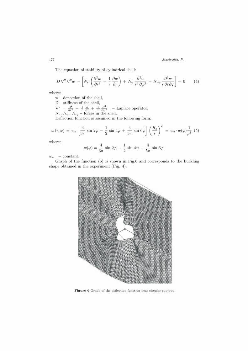
wa − constant.Graph of the function (5) is shown in Fig.6 and corresponds to the buckling
shape obtained in the experiment (Fig. 4).
Figure 6 Graph of the deflection function near circular cut–out
Analytical and Experimental Studies of Stability ... 173
Once the stress function (2) and deflection function (5) are substituted into stabilityequation (3), it is solved with Bubnov–Galerkin method. Orthogonal condition ofequation (4) has then the form:
5∫1
2π∫0
R (ρ, φ)w (φ)1
ρdρ dφ = 0 (6)
where:R (ρ, φ) − left side of the equation (4),1 ≤ ρ ≤ 5 − dimensionless radius.After transformations of the condition (6) the following equation for critical load
is obtained:102415π
E t2
12 (1− ν2)R2o= 10, 662σo (7)
or
2, 038E t2
12 (1 − ν2)R2o
= σo. (8)
The obtained value σo is a critical stress:
σkr = 2, 038E
12 (1 − v2)
(t
Ro
)2
(9)
Besides the orthogonal condition (6) two other ones are solved with the use of theorthogonal factors:
w (r , φ) = wa w (φ)1
ρ(10)
w (r , φ) = wa w (φ)1
ρ3(11)
They take the form:5∫
1
2π∫0
R (ρ , φ) w (φ) dρ dφ = 0 (12)
5∫1
2π∫0
R (ρ , φ) w (φ)1
ρ2dρ dφ = 0 (13)
The solution conditions (12) and (13) gave the following expression for the criticalstress:
σkr = 4, 09E
12 (1 − ν2)
(t
Ro
)2
(14)
σkr = 1, 3E
12 (1 − ν2)
(t
Ro
)2
(15)
If the deflection function is presented in the general form:
w (r , φ) = wa w (φ)1
ρn(16)
174 Stasiewicz, P.
and numerical coefficients in the formulas (9), (14) and (15) are denoted by k, thegeneral formula for the critical stress can be written as follows:
σkr = kE
12 (1 − ν2)
(t
Ro
)2
(17)
where:
k =
4.09 for n = 12.04 for n = 21.30 for n = 3
4. Conclusions
The critical stress value (17) was determined for n = 1 assuming:
• for steel: E = 205000 MPa, ν = 0,3,
• for brass E = 110000 MPa, ν = 0,3,
• for aluminium E = 69000 MPa, ν = 0,33.
Tab. 3 summarizes the critical stress values obtained experimentally and analyti-cally. The results are different depending on the diameter of the cut–out.
Table 3 Critical stress of the shells. Comparison of the values obtained experimentallyand analytically
R0 [mm]
σkr[MPa]Steel brass aluminiumAnalytical Exper. Analytical Exper Analytical Expe.
5 751 18 602 203 258 7014 92 115 77 117 32 58
The critical stress of shells with smaller cut–out obtained experimentally is sig-nificantly less than obtained analytically. The difference is caused by others geo-metrical imperfections and also by stress concentrations near rigid grip. For somespecimens with cut–out of 5 mm buckling occurs away from cut–out. On the otherhand in case of greater cut–out situation is different. Assumed deflection function(5) is only approximation of real behavior of the structure and depends on onefree parameter only. It is necessary to expand deflection function to get bettercompliance of both solutions.
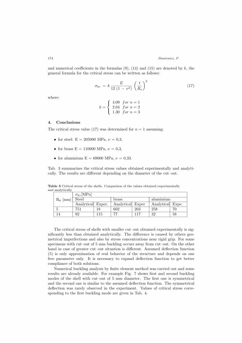
Numerical buckling analysis by finite element method was carried out and someresults are already available. For example Fig. 7 shows first and second bucklingmodes of the shell with cut–out of 5 mm diameter. The first one is symmetricaland the second one is similar to the assumed deflection function. The symmetricaldeflection was rarely observed in the experiment. Values of critical stress corre-sponding to the first buckling mode are given in Tab. 4.
Analytical and Experimental Studies of Stability ... 175
Figure 7 Graph of the deflection function near circular cut–out
Table 4 Critical stress of the shells obtained numerically (FEM)
R0 [mm]σkr[MPa]steel brass aluminium
5 606 406 215
Finite element analysis was performed for ideal structure, so critical stress ob-tained numerically has greater value then the determined experimentally. An ad-ditional detailed nonlinear buckling analysis with taking into account geometricalimperfections is necessary.
The main conclusions:
• Geometrical imperfections have a particularly strong influence on the criticalstress value for shells with small cut–out. For the shell with cut–out of adiameter less than 5 mm other imperfections have greater influence on thecritical load than the cut–out.
• Numerical investigations should be extended to non–linear model.
References
[1] Volmir, A. S.: Stability of deformable systems, Izd. Nauka, Fiz–Mat–Lit, Moskwa,1967.
[2] Staat, M.: Local and global collapse pressure of longitudinally flawed pipes andcylindrical vessels, International Journal of Pressure Vessels and Piping, Vol. 82,217–225, 2005.
[3] Aghajari, S., Abedi, K. and Showkati, H.: Buckling and post-buckling behaviorof thin–walled cylindrical steel shells with varying thickness subjected to uniformexternal pressure, Thin–Walled Structures, Vol. 44, 904–909, 2006.
[4] Ahn, S. H., Nam, K. W., Takahashi, K. and Ando, K.: Comparison of ex-perimental and finite element analytical results for the strength and the deformationof pipes with local wall thinning subjected to bending moment, Nuclear Engineeringand Design, Vol. 236, 140–155, 2006.
[5] Jullien, J. F. and Limam, A.: Effects of openings of the buckling of cylindricalshells subjected to axial compression, Thin–Walled Structures, Vol. 31, 187–202, 1998.
176 Stasiewicz, P.
[6] Vaziri, A. and Estekanchi, H. E.: Buckling of cracked cylindrical thin shells undercombined internal pressure and axial compression, Thin–Walled Structures, Vol. 44,141–151, 2006.
[7] Schenk, C. A. and Schueller, G. I.: Buckling analysis of cylindrical shells withcutouts including random boundary and geometric imperfections, Comput. MethodsAppl. Mech. Engrg, Vol. 196, 3424–3434, 2007.
[8] Meng–Kao, Y., Ming–Chyuan, L. and Wen–Tsang, W.: Bending bucklingof an elastoplastic cylindrical shell with a cutout, Engineering Structures, Vol. 21,996–1005, 1999.
[9] Alashti, R. A., Rahimi, G. H. and Poursaeidi, E.: Plastic limit load of cylin-drical shells with cutouts subject to pure bending moment, International Journal ofPressure Vessels and Piping, Vol. 85, 498–506, 2008.
[10] Wilde, R., Zawodny, P. and Magnucki, K.: Critical state of an axially com-pressed cylindrical panel with three edges simply supported and one edge free, Thin–Walled Structures, Vol. 45, 955–959, 2007.
[11] Timoshenko, S. and Goodier, J. N.: Theory of Elasticity, McGraw–Hill BookCompany, New York, Toronto, London, 1951.