Embed Size (px)
Citation preview

:'J: · -
: ·�
=·� : ',, . '·
. r
.. : . : ;j: . ... : : -: . ·�: '· . � : � · . :" : • : . ,;
. . ;�
. :t : .L . ' . ; : ' i ; . .. . . ... : , . . . . : �l
Modal Analysis: the International Journal of Analytical and Experimental Modal Analysis v 8 n 1 Jan 1993 p 55-62
by P. Salvini, Universita di Roma "Tor Vergata" and A. Sestieri, Universita di
Roma "La Sapienza"
ABSTRACT A method is developed to predict the dynamic behavior of a structure from experimental FRF data of the same
system subjected to different constraints. In particular it is required that the new structure undergoes more restrained conditions, but any type of ideal constraint, involving either translational or rotational degrees of freedom, can be accounted for. Among several interesting applications. the method can be used to overcome typical experimental drawbacks on rigid tested structures and to estimate untestable FRF terms of constrained systems. Numerical and experimental results are provided to show the consistency of the method and the possible range of applications.
Several problems exist in testing particular structures under given boundary conditions. Recently
Barney, et al[l J considered the problem of designing a support device, capable of separating the rigid body
modes of an unrestrained flexible structure from the structure's first flexural modes. In order to avoid the
difficulty of testing the structure in free-free conditions, the algorithm developed in Ref. [ 1] identifies the
free-free features of the considered structure from those of a multiply constrained system by means of a
direct procedure which uses a force measure at lhc boundary points.
However, not only free-free structures present critical testing conditions. The measurement of any
restrained system is often troublesome, too, and the experimental results differ significantly from the
theoretical ones. In fact:
• experiments on rigidly constrained structures (e.g., clamped-clamped beams) produce sometimes
unacceptable excitation conditions, as double peaks in impact excitation; • ideal rigid boundary conditions are very hard to obtain, so that the response of the tested structure is
highly affected by the modal behavior of the supporting system;
• the nature of the real constraints are generally very dissimilar from the designed ones, yielding
inevitably impredictable results.
In order to avoid the above fixes, the behavior of the actual system can be predicted from experiments
performed on the same structure, though subjected to unrestrained or less restrained conditions. This
P ietm Salvini, Dipartimento di I nge gneria M accanica, U ni versira di Rvma ''Tor Vergata.,
, ViaE. Carnevale- 0017 3 R oma, Italy. A /do
St·stieri (SEM memherJ, Profes:;or, Dipartimento di Meccanica e Aeronautica, Utzi\'ersitit di Rnma "La Sapienza", Via Eudossiana
18- 00184 Roma, Italy.
An earlier version of this paper was to have heen presenred at rhe 9'h lnlernational Modal Analysis C onferena. Florence ,Italy, April 1991. Final manuscripT received: July 20, 1992
55
;I • ' ' • '! - . : : . . ·' . � . . . :. . ; : .. .. ,. . � . • >! . : . - � ' ., . : . . : ; . "! . .
: � : ·! . ' � �
: J ; : ·. . '· . :·. ·' . . '
. . ': , .
: ,!.: : : · ' . .
' ., i
. : � · ; ' .
. ; . ' '
; :; . . � . ;
. •} ' . ; . . ' ' ·'
l ! . .,.
:
i ; •
'?
:
' . •• "') . j : · j! ., ,
.lj •t· . . .
procedure is simple when accomplished on theoretical discrete systems, e.g., obtained by finite elements,
provided that the mass and stiffness matrices of the unrestrained system are known. When, on the contrary t
the less constrained structure is identified from its experimentally determined frequency response function
{FRF), other procedures can be followed to determine the new FRF. The method of general constraints [2] provides the FRF of a structure, after introduction of any set of linear constraints, and some applications
are being developed [3,4]. In this paper a new procedure is presented, which is in principle more simple
than the previous one. The method may have interesting engineering applications. • It can be used to check the effect of adding constraints on the modal behavior of the system or on
the forced response of the structure subjected to external forces. • It may be helpful to model the actual constraints acting on a tested structure, when the boundary
conditions cannot be easily identified, e.g., when dealing with non-ideal constraints. • [t represents an effective way to obtain an optimal constraint location, when different solutions are
available for the designer.
• Moreover, it basically represents a predictive method of structural modification that can be
employed in developing an optimization procedure without requiring any modal identification on
the original data. Modal identification, in fact, can lead to erroneous estimates of structural
modifications, as it was shown by several authors in the last decade (see, e.g., Elliot and Mitchell
[5] and Braun and Ram [6]). • Finally, the method can be advantageous! y applied to estimate the FRF of coupled structures when
the related substructure parameters are quantities difficult to determine experimentally.
Any type of ideal constraint, involving either translational or rotational degrees of freedom, can be
considered. The method is developed here for any possible increment of constraints. It only requires that
the FRF matrix of the origina1 system be measured at the points where further constraints must be applied,
along the whole set of degrees of freedom affected by the constraints.
The input -output relation for a linear, time invariant dynamic system can be expressed in the frequency
domain as
{x(ru)} = [H(m)]{f(m)} (1)
.. Here I ,r( m)) includes both linear ( x) and angular ( 8) accelerations and {f} includes both forces (F) and
moments (M); consequently the elements of the [H) matrix (FRF) involve translational as well as rotational
degrees of freedom (DOFs ). The experimental evaluation of rotational FRF elements is not very accurate
because rotational accelerometers are only recently becoming feasible and there is not sufficient
experience with them. Furthermore, lumped moments are not easily applicable. Different solutions have
been proposed to compute the rotational terms [7,8,9]. Among them, the use of a finite difference scheme
involving translational measurements [8] and modal curve fitting [7] are, up to now, valuable techniques . � . .
used to compute the translational-rotational ( 8 /F, .X /M) and rotational-rotational ( 8 /M)tenns respectively,
at least for beam-type structures. Based on these algorithms, these authors have recently developed a
technique for predicting the assembled structure behavior, considered the sensitivity of the computed FRF clements to the finite difference spacing and the importance of low and high residuals on the accuracy of res u Its f I 0 ].
In order to derive the FRF matrix of a structure subjected to additional constraints from the knowledge
of the FRF of a less restrained structure, let us consider a system having a+ c DOFs, where c DOFs have
to be constrained. A DOF constraint is meant here as a condition of null acceleration. Equation ( 1 ), written
56 January 1993
' !} : i · . i �: ! . . . ' ' ' . . . . . .
. . ' .
... ' � . ' :: . .
. , . : � : ' <. ' � . · .. . . . . ' .
·t . ' �: ' · � . : � . ' ' \: .. ' : ' ; '
f:: . ' ' :. : . '
?i ... . ' i � . � ! ' . ' �.: ' •. :
fi
.� ..
.J' .. , ' t. ::. . '
for the original system, can be partitioned as follows
{X a} _ [ H a a ] [Hat'] { J�} {xc} - [ Hca] [ Hu.] {Jc.}
The constraint condition on the c DOFs implies
from which the constraint forces can be determined
By substituting Eq. (4) into Eq. (2)
the new FRF matrix [�a], with constraints on the c DOFs can be calculated, i.e.,
(2)
(3)
(4)
(5)
(6)
Therefore, by considering the dynamic effect of the constraints we obtain the new FRF of the more
constrained structure. The procedure only involves simple matrix operations, besides a matrix inversion
of order equal to the number of the degrees of freedom of the added constrains.
The previous relationship can be put in a more general expression which includes the change due to
structural lumped modification, i.e., the addition (or subtraction) of mass, stiffness and damping on some
points of the structure. This result could be particularly useful in developing a general optimization
technique for vibration control, though the presence of external constraints is exclusively binary in contrast
with structural modification, whose amount can be continuously graded .
Let a be the set ofDOFs where the new FRF must be computed, b, the set ofDOFs amenable to structural
modification, and c the set of DOFs where further constraints must be imposed. It is obviously
{b} c {a} (7)
and
{c} r({b} u{a}) = {0} (8)
Let rahh] be a structural modification matrix (apparem mass, i.e., force over acceleration). The diagonal
terms of it are inertial modifications or stiffners and/or dampers connected with a fixed point, while the off
diagonal terms represent stiffners and/or dampers between points of the structure [9]. We can rewrite Eq.
(2) subdividing the DOFs according to the above stated groups as follows
Modal Analysis 57

: ·.
'
' 'j . .
I
.
'
' :.
. .
. '
.
. . . .. . · . . · . ...
. . ..
' :· .. . .
. ' .
. :
.
i
: . . .
' .
,
. '
.. . . . .
{ xa} = [ Haa ]{fa}+ [ Hab ]{Jb} + [ Hab ][ B"" ]{ xb} + [Hac ]{fc} { x"} = ( Hba ]{fa}+ ( Hbb ]{.fb} + [ Hhb ][Bhb ]{xh} + ( Hhc ]{fc:} {Oc} = ([ Hca ]{fa}+ [ Hcb ]{Jb} + [ Hcb ][ Bbb ]{xb }) + [ Hcc ]{fc}
(9)
By deriving U;.} from the last equation of the previous system, the new FRF of the system undergoing
further constraints and/or structural modifications can be written, after some algebraic manipulation, as
(10)
[H*l is obviously a symmetric matrix. This expression computes the FRF matrix among the whole set of
DOFs a+ b, either amenable of structural moditication or not. The FRF terms among constrained DOFs
care obviously meaningless.
The solution ofEq. ( 1 0) requires two inversions. The first is of order c, equal to the constrained DOFs,
the second of order b, equal to the DOFs introduced by structural modifications.
Two different applications of the method to structural problems are worthy of particular emphasis. The
first one concerns the passive control of vibrating structures; the second, the FRF estimation of a structure
from the knowledge of the experimental FRF of its break-down components.
A well developed technique for vibration control is structural modification. Structural modification
involves three main related problems: prediction, sensitivity and optimization. The predictive approach
determines the FRF of a structure once some kind of modification (either concentrated or distributed) is
performed on it. The sensitivity approach can be used to estimate the optimal location on which to introduce
an established modification. The optimization approach provides a set of optimal modification values and
locations in order to obtain an established dynamic behavior. In Ref. r II] a non-linear optimization
technique has been developed for lumped modification. The ex pression derived in Eq. ( 1 0), accounting for
both lumped modifications and increment of constraints, could be advantageously used for design
optimization. In fact, the combined action of these two procedures can provide a more effective vibration
and/or acoustic control when suitable weights are introduced into the objective function which specifies
the cost of the whole operation.
The second mentioned problem concerns the coupling of structures. When the FRF of a coupled
structure must be determined from the know ledge of the ex peri mental FRF of its break -down components,
rotational FRF tenns must be accounted for. The recent availability of angular accelerometers now makes
the estimates of the rotational-translational FRFs more friendly but it is still difficult to measure the
rotational-rotational quantities. A successful way to determine the rotational terms, even without using
58 January 1993

. . ' . ' . .
. . . . . . ·. · ' . . . . . ' ... : ·,: ' ...
.: . .. .. " . : : :
: �.; . . ':· ·:< ... '-: . . • .
' f. : i .: ' ; . ' ·., ' ( : � : : ·;. . .. . ' . . . . ' ... ' . ' : : �:
' . 'i. ' . ·i ' ' ; ... . ' .
; · , ' ., ..
'
'l" . ' ! ' . : ' .
. ' . . :·.
' : . ' ;1: .. ' : .• . .
i • ' t . ' :..• :·�.; . ' · . . . ' . ' ' :, . : . � · : . ' ... . . ' ·: ' .. . .i
':� .. ' .:.
i
:· • . . . . . .. ; .; .
y: . • . '" . . ' ' � .
i
·''
'
·.� . . ' .
'
'I.' .: ·J I ::·J • '! �'·IL ., . •. • ·1 ···fJ ' i., i ;j' ij l . '
11 �j ; 'j' : ' . . ; . • .
. . . ; ; , : ·.t:�
.
,
. ,. ! , .
·.1· i � t. '
I
'·. : ' ' ·
angular accelerometers, is performed through the computation of first and second order derivatives, corresponding to rotational-translational and rotational-rotational elements, respectively, [8]. A finite difference scheme that uses translational FRF data only can be employed to determine the first derivative, while a curve fitting procedure is numerically more efficient to estimate the second derivative [7]. However, in particular situations, e.g., when a structure must be welded to the pinned end of a beam, it is necessary to determine, for coupling purposes, the rotational FRF elements at the support of the beam.
In this case it is not possible to measure translational quantities at the support, and even very close to it. the FRF terms are unreliable because of the low coherence. In fact, close to the supports, the level of the response is usually very low, and the noise, always present in the experiments, makes the signal to noise ratio increasingly poor as the constrain position is approached. To overcome this drawback the problem can be solved in two steps, following the lines previously developed. First the support of the beam is eliminated and the rotational terms at this end are computed through finite difference and curve fitting,
using the measured translational data. Then Eq. (6) is used 10 detennine the rotational term at the support, which is necessary to compute the FRF of the whole system. A practical application of this procedure is exposed in the following section.
A first set of simulation tests was performed on an aluminum beam in order to check the consistency of the described approach. The beam characteristics were as follows: E = 6.35 · 1010 N/m2 Young's modulus, p = 2700 kg/m3 material density, A= 3.2 · 10·4 m2 cross-area, I = 1 .7 · l0-9 m4 cross section moment of inertia, l = 0. 7 m length of the beam.
In these tests, comparisons were made between FRF elements (translational and/or rotational) of the actual constrained beam, computed (i) directly from the homogeneous equation of motion, and (ii)
determined through Eq. (6) which uses FRF data of a less constrained beam. For example. the FRF of a hinged-hinged beam may be determined theoretical] y or computed from Eq. ( 6 ), by employing the FRF of the same system with few constraint conditions. as a free-free or hinged-free beam.
A problem arising in comparing FRF theoretical results, obtained as a sum of contributions of vibrational modes, concerns the number of modes that must be considered. In the following tests the analyzed frequency range (0 - 800Hz) includes the first 3 or 4 natural frequencies of the examined beams. The number of modes, used to compute the FRF elements theoretically, can affect considerably the estimated FRF s. As it will be seen later, mode truncation causes an overestimate of the natural frequencies, and this effect increases for the higher modes.
3
1 = 0.7 m
h - 0.05 m
Fig. 1 Measurement point locations in the beam examined
-
rr '2FoTTT'' '<460 I ITT, T '60o ,,TTl II ado Frequency (Hz)
Fig. 2 Clamped-hinged beam: i ,1� -- reference theoretical value ------ derived from clamped-free beam
Modal Analysis 59
.· . , . ;
. .
. . ' . .
. . ' : . '
. . ' . . . . .
. '. : ·. ' .
. ' .
. .
' ..
:
·: ' ; ' . ' ..
. , ' . ' .
; :� . .. i .� . ' ' '
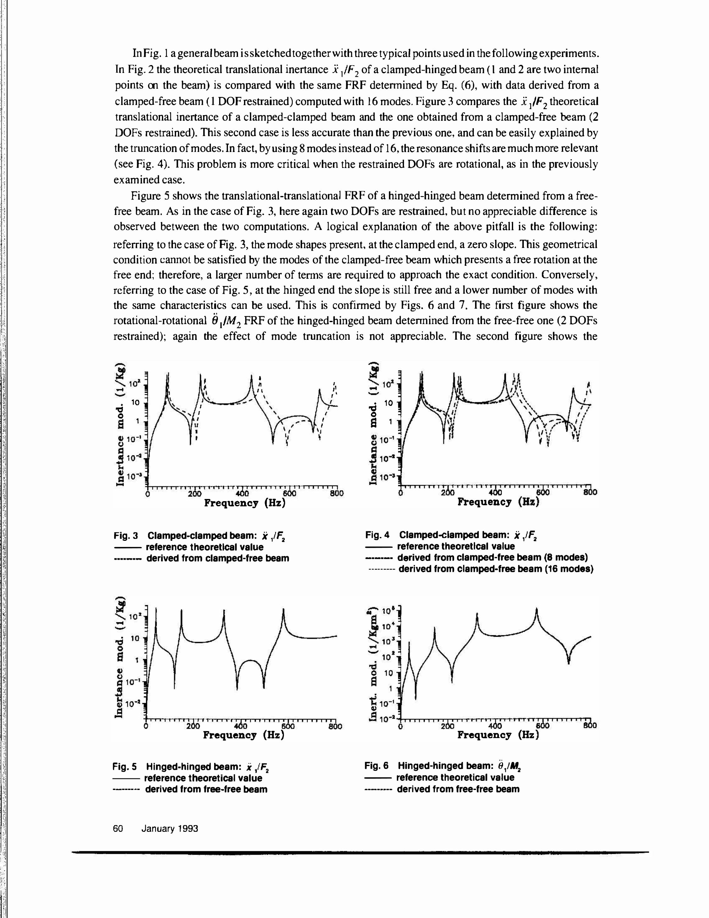
In Fig. 1 a general beam is sketched together with three typical points used in the following experiments .
In Fig. 2 the theoretical translational inertance x /F2 of a clamped-hinged beam ( 1 and 2 are two internal
points on the beam) is compared with the same FRF detennined by Eq. (6), with data derived from a
clamped-free beam ( 1 DOF restrained) computed with 16 modes. Figure 3 compares the i /F2 theoretical
translational inertance of a clamped-clamped beam and the one obtained from a clamped-free beam (2 DOFs restrained). This second case is less accurate than the previous one, and can be easily explained by
the truncation of modes. In fact, by using 8 modes instead of 16� the resonance shifts are much more relevant
(see Fig. 4). This problem is more critical when the restrained DOFs are rotational, as in the previously
examined case.
Figure 5 shows the translational-translational FRF of a hinged-hinged beam determined from a free
free beam. As in the case of Fig. 3, here again two DOFs are restrained, but no appreciable difference is
observed between the two computations. A logical explanation of the above pitfall is the following:
referring to the case of Fig. 3, the mode shapes present. at the clamped end, a zero slope. This geometrical
condition cannot be satisfied by the modes of the clamped-free beam which presents a free rotation at the
free end; therefore, a larger number of tenns are required to approach the exact condition. Conversely,
referring to the case of Fig. 5, at the hinged end the slope is still free and a lower number of modes with
the same chamcteristics can be used. This is confirmed by Figs. 6 and 7. The first figure shows the .. rotational-rotational (J 11M2 FRF of the hinged-hinged beam detennined from the free-free one (2 DOFs
restrained); again the effect of mode truncation is not appreciable. The second figure shows the
• 10 � 0 s 1
f I
I I \
, , I
II I I
• II I I
\
, ,I I '
' I '
' I \ ' , - ' , , \
:COo Ti I I 1 1 r 60o" I I I I I I SOO Frequency (Hz)
Fig. 3 Clamped·clamped beam: x /F2 -- reference theoretical value ····-·- derived from clamped-free beam
-
Frequency (Hz)
Fig. 5 Hinged-hinged beam: x ,JF2 -- reference theoretical value -------- derived from free-free beam
60 January 1993
-
• 10 -a 0 s 1
Frequency
Fig. 4 Clamped...clamped beam: x ,IF2 -- reference theoretical value -·-·-· derived from clamped-free beam (8 modes)
··-··----derived from clamped-free beam (16 modes)
Frequency (Hz ..
Fig. 6 Hinged-hinged beam: 8 ,1M2 -- reference theoretical value ----··-- derived from free-free beam

translational-translational FRF of a clamped-clamped beam, derived from free-free conditions (4 DOFs
restrained) which presents again the observed resonance shifts. However, excluding the effect of mode
truncation, the discussed simulated results confinn that the method is straighforward. Moreover the pitfall
of modes truncation is only important when theoretical data are used. For experimental data, the FRF
elements always account for high residuals, due to the effect of out-of-range modes, thus not affecting the
derived results.
A second set of tests was then performed to verify the reliability of the procedure on experimental data.
The drive point inertance element .Xi F 3 at the end of afreejree aluminum beam and other two t��nslational
elements, at points very close to the end, were measured. The inertance elements ,( iM3 and 9/M3 were
determined, using the experimental translational FRFs only.The first element was computed by means of
the. finite difference scheme; the second, through modal identification. With these data the rotational
rotational FRF element of a hinged-free beam, at the hinged end, was computed by means of Eq. (6).
The rotational-rotational FRF term of the hinged-free beam was then determined via translational
theoretical data by applying the finite difference and identification algorithm described in Ref. [ 8]. In order ••
to compute the term 9/M, a forward finite difference was used on the translational data computed very close
to the hinged end. (Note that the measurement of the FRF term at the hinged end is troublesome due to the
difficulty of measuring translational accelerations with a good signal to noise ratio very close to a fixed
end). The rotational-rotational FRFs obtained from these two approachs are compared in Fig. 8, together
with the analytical solution. The advantage of the proposed procedure should be evident considering that ..
the theoretical FRF 9/M, computed in the proximity of the constraint, is surprisingly less accurate than the
experimental one. This confirms the reliability of the proposed method. the possibility of using it for
coupling purposes, as well as the difficulty of obtaining particular FRF terms from constrained systems.
A straightforward method is proposed here to compute FRF elements of any constrained structure from
data derived from the same system, though less strictly constrained. Besides the ease and opportunity of
testing more flexible systems, involving minor experimental inconveniences, several practical applications
can be immediately carried out: • determine the FRF matrix of a system, tested under different constraint conditions;
• predict the effect of adding constraints on mode shapes, natural frequencies, or on the forced response of a structure;
-
� 102 --
• 10 � 0 s , '
Q) (> 10-1 = t 10-1 t) -=!
•I ' ! ,A ,, : \ I � •• , • ' J\l •,
,,, � � ' ' - .-r' ' �-�·--�-· ' ll - \ ',
ll ' ",, • \.-"'"t< ' 1,• • \'4: \ I \
�'· ,, \: " � • '
_ .. � ,
- 10-� 'ioo 'T TT"T"1., '43() T r·r T I I 'soc I'T I I f I I Bllo Frequency (Hz)
"
Fig. 7 Clamped-clamped beam: 8 ,fF2 -- reference theoretical value -----·- derived from free-free beam (8 modes) --------- derived from free free beam (16 modes)
td 102 0 El 10 i 1 � 10.1 -
I •
Frequency (Hz) ..
Fig. 8 Hinged-free beam: 9jltf3 -- reference theoretical value ·-·-·- experimental derived from tree free beam --------- derived from translation inertance by Finite Difference
Modal Analysis 61
' .:. .
. : .· . . . . . . . . :\ .. . . . . .
. r
.
. . ' ; .
; : . . : . . .
" ·t
-� t • . > � t • ' : ' . ' . : ;' :!' � .... .
.
. i 1 'I ' ! : ' ' . ' : .
' 1 :. ' : .
; t
II
• f onnulate a general optimization procedure for passive vibration control accounting for a combined
action of structural modification and constraint conditions; • predict the FRF tenns which are difficult to measure directly, though necessary to couple different
structures; • choose the best configuration of constraints.
The method is proved to be very effective and does not present general ill-conditioning limits as it was
proven on the experimental data.
This work was supported by MURST (Italian Ministry of University and Scientific Research) through grants 40% and 60%.
[1] Barney, P.; Rost, R.; Brown, D. "Identifying Free-Free Systems Characteristics from Multiple
Constraint Boundary Tests." Proceedings of the 15rh International Seminar on Modal Analysis,
Leuven, Belgium, 1990. v 3 p 1161-117 4
[2] Crowley, J.R.; Rocklin, G.T.; Klosterman, A.L.; Void, H. "Direct Structural Modification Using
Frequency Response Functions." Proceedings of the 2M International Modal Analysis Conference.
Orlando, FL, Feb. 6-9, 1984. v 1 p 58-65
[3] Crow ley, J.R.; Void, H. "Structural Modification and Sensitivity Through aM ulti-Point Constraint
Formulation." Proceedings of the 5'h International Modal Analysis Conference, London, England,
Apr 6-9, 1987. v 2 p 928-933
14] El liot, K.B.; Mitchell, L.D. "The Effect ofModal Truncation on Modal Modification." Proceedings
of the 51h International Modal Analysis Conference, London, England, Apr 6-9, 1987. v 1 p 72-78
L5 J Braun, S.; Ram, Y.M. "On Structural Modifications in Truncated Systems." Proceedings of the 5r11
International Modal Analysis Conference, London, England, Apr 6-9, 1987. v 2 p 1550-1556
[6] Larsson. P.O. "Dynamic Analysis of Assembled Structures Using Frequency Response Functions:
Improved Formulation of Constraints." lnt J Anal Exp Modal Anal v 5 n 1 Jan 1990 p 1-12.
171 Ewins, D.J.; Gleeson, P.T. "Experimental Determination of Multidirectional Mobility Data for
Beams.�' Shock Vih Bull v 45 1975 p 153-173.
[ 8] Sattinger, S.S. "A Method for Experimentally Determining Rotational Mobilities of Structures.''
Shock Vih Bull v 50 1980 p 17-27.
r91 O'Callahan, J.C.; Avitabile, P.; Madden, R. "'An Efficient Method of Determining Rotational
Degrees of Freedom from Analytical and Experimental Modal Data." Proceedings of the 4'h International Modal Analysis Conference, Los Angeles, CA, Feb 3-6, 1986. v 1 p 50-58
II OJ Sestieri, A.; Salvini, P.; D' Ambrogio. W. "Reducing Scatter from Derived Rotational Data to Detennine
rhe FRF of Connected Structures." M ech Syst Signal Process v 5 n I 1991 p 25-44.
[II J Sestieri, A.; D 'Ambrogio, W. '"A Modification Method for Vibration Control of Structures." M ech
Syst Signal Process v 3 n 3 1989 p 229-253.
62 January 1993


