Embed Size (px)
Citation preview
This article has been accepted for inclusion in a future issue of this journal. Content is final as presented, with the exception of pagination.
IEEE TRANSACTIONS ON PLASMA SCIENCE 1
Analysis on Triggering and Discharge Characteristicsof Three-Electrode Trigatron Gap
Li Cai, Lee Li, Fuchang Lin, Member, IEEE, Xiangdong Qi, Chaobin Bao, and Wu Zhou
Abstract—The development of a three-electrode trigatron gapwith the trigger electrode inside the main electrode is discussed inthis paper. Two models of the operation mechanism are proposedto explain the breakdown in the trigatron gap. In addition, amathematical model was proposed to calculate the breakdowntime based on the theoretical analysis. The influence of differentparameters on the breakdown time is discussed. Some character-istics in dry air have been experimentally determined such as theinfluence of the air pressure and the influence of the undervoltageratio on the spark gap operation. The experimental results showthat the operating voltage range between 0.5 and 0.7 might be rea-sonable. Then, the experimental results and analysis demonstratethat there are three regions divided by two inflection points, andthe corresponding values of the undervoltage ratio are thresholdvalues presenting different breakdown processes.
Index Terms—Breakdown time, jitter, trigatron gap, undervolt-age ratio.
I. INTRODUCTION
H IGH PULSE voltages and currents could be generatedby the power module. The wave form of pulses is not
only determined by the pulse-forming elements but also bythe discharging characteristics of the spark gaps. Therefore,the three-electrode trigatron gap with a trigger pin inside themain electrode has achieved wide popularity because of its fastcollapse and low jitter.
In the past several years, lots of theoretical and experimentalresearch works have been done. Lots of influence factors onthe characteristics of the gap have been demonstrated, suchas the effect of air pressure on the range of working voltage[1], the effect of polarity on the switching performance [2],and the influence of the gas insulation parameters on the trig-gering characteristics [3], [4]. Many investigations were madeto improve the recovery rate and the repetitive operation ofgas switches [5]–[7]. In addition, to represent a series of keyparameters related to useful lifetime, the erosion of the triggerpin and the main gap after thousands of Coulomb transfers wasdiscussed [8].
Manuscript received August 28, 2011; revised December 5, 2011 andFebruary 29, 2012; accepted March 23, 2012. This work was supported in partby the National Natural Science Fund, China, under Grant 51107049 and inpart by the Independent Innovation Fund, Huazhong University of Science andTechnology under Grant 2011QN093.
The authors are with the State Key Laboratory of Advanced Electro-magnetic Engineering and Technology, Huazhong University of Scienceand Technology, Wuhan 430074, China (e-mail: [email protected];[email protected]; [email protected]).
Color versions of one or more of the figures in this paper are available onlineat http://ieeexplore.ieee.org.
Digital Object Identifier 10.1109/TPS.2012.2192941
Fig. 1. Schematic of the trigatron structure.
Among these characteristics, the breakdown time attractsmuch attention since it is an important performance for theswitch. This paper describes the mathematical model of thebreakdown time and the undervoltage ratio (working voltagedivided by self-breakdown voltage) based on the gas dischargemechanism. After that, an experimental verification is per-formed, and values of the delay time changed with workingundervoltage ratio and air pressure were measured to clar-ify the physics of the discharge and the optimum operatingconditions.
II. THEORETICAL ANALYSIS
Three-electrode trigatron gap is widely utilized because ofits simple structure. As shown in Fig. 1, it was composedof main electrodes (the opposite electrode and the adjacentelectrode) and the trigger pin, which is located inside theadjacent electrode. The gap between the trigger pin and theopposite electrode is the main gap, whereas that betweenthe trigger pin and the opposite electrode is the trigger gap.
Previous study has shown that the three-electrode trigatrongap has two breakdown mechanisms [9]. Fast-breakdown mode(mode 1) is when the trigger pulse is applied to the trigger pinand the breakdown between the trigger pin and the oppositeelectrode takes place first. After the main-gap voltage hascollapsed, the breakdown of the trigger gap will generate undera high degree of overvoltage. The second mechanism slow-breakdown mode (mode 2) is that the breakdown across thegap between the trigger pin and the adjacent electrode takesplace first. The intense UV radiation is believed to produce freeelectrons through photoionization. Afterward, the initiation ofan electron avalanche in turn leads to the breakdown of the maingap. The advantages of mode 1 are short breakdown time andlow jitter, but its defect is serious erosion of trigger pin because
0093-3813/$31.00 © 2012 IEEE

This article has been accepted for inclusion in a future issue of this journal. Content is final as presented, with the exception of pagination.
2 IEEE TRANSACTIONS ON PLASMA SCIENCE
of the main current passing through the trigger pin in initialdischarge. On the contrary, mode 2 would have a long lifetimewith low erosion, although the breakdown time is relativelylong with microsecond level [10].
Time delay can be defined as the time between the triggerpulse arriving at the trigger pin and the voltage on the maingap starting to decline. The time delay can be divided intotwo parts, i.e., the rise time of the trigger voltage tr and thebreakdown time of the main gap t. Time delay can be written astd = tr + t. As for the fast-breakdown mode (mode 1), it canbe given that t � tr. As for the low-breakdown mode (mode 2),it can be given that t > tr. The breakdown time in this papermeans the breakdown time of main gap t, and it can bemeasured by monitoring the voltage shape on the trigger pinand the HV electrode.
Based on the aforementioned, a mathematical model wasproposed to analyze the breakdown characteristics of the three-electrode trigatron gap. It is considered that the energy of thetrigger pulse is large enough to lead to trigger gap breakdown.
The width of the trigger gap is dt, whereas that of the maingap is dg . The switch is charged to a dc voltage Um to theopposite electrode. The static mean E-field in the main gap Em
is Um/dg .When voltage is applied to the trigger electrode, a spark
occurs. It leads to a higher electron ionization rate coefficientα0 than that in the previous static electric field. The electronionization rate coefficient α0 is dependent on electric E and thepressure of the filled gas p [11], i.e.,
α0 = Ape−Bp/E (1)
where A and B are constants, which are related to the propertiesof the gas. Both of them can be determined by experimentalresults.
It is considered that the trigger voltage is the function ofthe air pressure, the rate of rise of the triggering pulse, andother properties of trigger gap, such as gap distance and ma-terial. When the trigger voltage Ut is applied, the enhancedE-field Etm near the trigger pin is KE(Um − Ut)/dg , wherecoefficient KE represents the E-field enhancement coefficientdetermined by the geometry of the trigger pin and the verti-cal position of the trigger pin relative to the earth electrode.However, coefficient KE is difficult to calculate or measure.To simplify the model, while gas pressure p remains constantboth before and after discharging, it could be assumed that theequivalence value of the electric field in the main gap could beexpressed by a coefficient, i.e.,
Etm0 = λEm (2)
where Etm0 is the mean E-field enhanced by the trigger pulse,λ is an equivalent coefficient related to the trigger pulse energyand the properties of insulation material of trigger gap. If λ = 1,that means that the mean E-field of the main gap is equal to thestatic mean E-field without the trigger pulse.
The average velocity of the electron avalanche vc0 can becalculated by the following formula [12], in which Etm0 is in
volts per centimeter, p is in pascals, and vc0 is in centimetersper second:
vc0 = 1.25 × 10⁷ ×√
Etm0 × 133.340 × p
. (3)
The electrons are emitted from the cathode and result inan avalanche. The electrons moving distance χ0 from theavalanche to the streamer can be calculated from the Raetherbreakdown criterion, i.e.,
α0χ0 = 17.7 + lnχ0. (4)
Based on this, the developing process of discharge can bedistinguished into two cases. In one case, it can form stablestreamer discharge with χ0 ≤ dg . Once a streamer forms, themoving time of the electron in this process is equal to thedistance divided by excursion velocity ve0, which is a functionof the E-field and the gas pressure [13], in which ve0 is incentimeters per second, i.e.,
ve0 =(
274 × Etm0
p+ 39.1
)× 105. (5)
To sum up, the breakdown time t of the gap is given by
t =χ0
vc0+
dg − χ0
ve0subject to χ0 ≤ dg. (6)
Otherwise, with χ0 > dg , it may not have attained sufficientnumber of collisions to form the streamer when passing throughthe distance of the main gap. Self-sustaining discharge wouldonly rely on the γ process.
The γ process is composed of the γi and γp processes. Theγi process is caused by collisions of ions with the cathode,whereas the γp process is associated with the mechanism oflight emission. As it is recorded in [11] and [14], the γi processis sharply reduced, and photoemission is often predominant atabout atmospheric pressure and E/p ≈ 30−40 V/(cm × torr).In addition, the time delay could reach 10−6 s or less, while thephotonic process is much more effective [15]. Since the exactfunctional relation between γp and α0 has not be determinedyet, a simple equivalent was presented so that coefficient γcould be expressed in the form of kγi (k ≥ 1). Meanwhile, thecoefficient γi can be calculated from
Ub =Bpdg
ln[
Apdg
ln(1+ 1
γi
)] . (7)
It is assumed that the number of initial electrons in UVionization is n0 when the trigger pulse is applied; thus, theequivalent increment of the enhanced E-field is decided by(2), i.e.,
ΔE0 = (λ − 1)Em. (8)
The number of secondary electrons n1 near the cathode iskγin0(eα0dg − 1) calculated by the γ process. The criterion for

This article has been accepted for inclusion in a future issue of this journal. Content is final as presented, with the exception of pagination.
CAI et al.: TRIGGERING AND DISCHARGE CHARACTERISTICS OF TRIGATRON GAP 3
self-sustaining discharge is
kγi(eα0dg − 1) ≥ 1. (9)
If the number of secondary electrons does not satisfy cri-terion (9), the discharge process would stop. Subject to cri-terion (9), if χ1 decided by the Raether breakdown criterionis greater than dg , the secondary-electron emitting from thecathode would result in streamer discharge. Otherwise, the nextγ process begins as the cycle repeats, which may eventuallylead to a breakdown or not.
When γ process leads to self-sustaining discharge, the equiv-alent increment of the enhanced E-field ΔE1 caused by thesecondary electron n1 is in proportion to ΔE0 caused by initialelectrons n0. Thus, according to (8), it is acquired that
ΔE1 = kγi(eα0dg − 1)(λ − 1)Em. (10)
Thus, the equivalence value of the electric field after one γprocess could be expressed by
Etm1 = Em + kγi(eα0dg − 1)(λ − 1)Em. (11)
Positive ions in the electric field are a relation of the functionthat depended on E/p. As the γ process is a variable processthat begins together with the initial electron avalanche andfinishes with secondary-electron emitting, the electric field inwhich positive ions travel to the cathode could be calculatedby 1/2(Etm0 + Etm1). Since that ion is much bigger than theelectron, the excursion velocity vi of the ion is 10−3 − 10−4
times higher than that of the electron [15]. Therefore, theaverage velocity of the positive ions could be expressed by
vi1 = vc × 10−3
= 1.25 × 10⁴ ×
√[0.5 × (Etm0 + Etm1)] × 133.3
40 × p.(12)
An example listed below is given for illustration. The airpressure p is 200 kPa, and the main gap dg is 0.6 cm. The valueof λ is set as 2. While the switch is charged to a dc voltageUm of 18 kV to the opposite electrode, the drift velocity couldbe calculated under the given fields and pressures. Therefore,the drift velocity of the electron is 1.24 × 107 cm/s, and thedrift velocity of the ion is 8.93 × 104 cm/s.The values are ofthe same order of magnitude as the previous research’s results[11], [15].
Positive ions formed with electron avalanche simultaneouslydecrease under the influence of recombination. While the elec-tron avalanche propagates to the anode, the head electronsof the electron avalanche neutralize the charge in the anode.However, the maximum density of positive ions is in the headof the electron avalanche. To represent an extreme case, themoving distance of positive ions leading to secondary electronsis assumed to be dg , that is to say, positive ions move from theanode to the cathode for secondary-electron emitting. Then, themoving distance χ1 of secondary electrons could be calculatedby the Raether breakdown criterion.
Therefore, the avalanche may not attain sufficient electric en-ergy to form the streamer when passing through the distance of
the main gap. The formation of self-sustaining discharge needsto rely on the second ionization process in which photon impactis predominant. In the condition of χ1 ≤ dg , the breakdowntime t of the gap is given by
t =dg
vc0+
dg
vi1+
χ1
vc1+
dg − χ1
ve1
subject to χ0 > dg, χ1 ≤ dg (13)
where vc1 and ve1 are calculated with Etm1 substitute for Etm0
by (3) and (6), respectively.Breakdown might occur with one or more times of secondary
avalanche. Equation (13) has discussed the situation of onesecondary avalanche. Then, the breakdown with two or moretimes of secondary avalanche is given by (14). The breakdowntime t of the gap can be written as
t =i−1∑k=0
dg
vc(i)+
i∑k=1
dg
vi(i)+
χ(i)
vc(i)+
dg − χ(i)
ve(i). (14)
In an inhomogeneous electric field, when δdg is not great(magnitude of 105 Pa × cm), the breakdown voltage of gap isgiven by an empirical equation [16], i.e.,
Ub =[6.7 ×
√δdg + 24.6 × (δdg)
]F. (15)
In this expression, Ub is the breakdown voltage (in kilovolts),F is the electric-field enhancement factor, and δ is the relativeair density of gas. It is charged with dry air in the trigatron gapswitch; thus, δ can be described as
δ =2.89 × 10⁻³ × p
273 + tT(16)
where tT is the Celsius temperature. Adding (15) and (16),the breakdown voltage function of the trigatron gap can bewritten as
Ub =
⎡⎣6.7 ×
√2.89 × 10⁻³ × pdg
273 + tT+ 24.6
×(
2.89 × 10⁻³ × pdg
273 + tT
)]F. (17)
Generally, the value of the work voltage on the trigatrongap is lower than that of the breakdown voltage in order toreduce the probability of self-break. The undervoltage ratio w isequal to the working voltage Um divided by the breakdown vol-tage Ub; it can be written as
w =Um
Ub. (18)
Add the previous (1), (2) and (11), one can obtain Etm0 andEtm1, respectively.
Uniting the aforementioned equations, the breakdown timefunction of the trigatron gap could be briefed as
t = f(w, p, dg, λ, k, F, tT ). (19)

This article has been accepted for inclusion in a future issue of this journal. Content is final as presented, with the exception of pagination.
4 IEEE TRANSACTIONS ON PLASMA SCIENCE
Fig. 2. Flowchart of breakdown-time simulation.
III. SIMULATION RESULTS
For a designed trigatron gap, dg , γ, F , and tT are all knownor can be calculated; thus, t could be rewritten as a functionof w, p, λ, and k, which is shown as t = f(w, p, λ, k). Therelationship of the breakdown time versus the undervoltageratio can be obtained by using a software program.
The simulation program can be performed based on the flow-chart shown in Fig. 2. Parameter i in the flowchart representsthe number of times of the γ process leading to breakdown.However, a large number of positive ions may disappear underthe influence of recombination. To simplify the simulation, itis considered that the breakdown takes place no more thanfive times of the secondary-electron emitting process. Wheni is greater than five, it is considered that the gap fails tobreak down.
In the simulation, the main gap is 0.6 cm, and the trigger gapis 0.2 cm, while the filled gas is air, and its pressure is 100 kPa.The trigger voltage is set as 5 kV. The ambient temperature is20 ◦C, and coefficient F is 1. Other constants are set as follows[13]: A = 11/(m × Pa) and B = 273.8 V/(m × Pa).
Fig. 3 shows the calculated breakdown time plotted versusthe undervoltage ratio for the equivalent coefficient λ of 1.5,2, and 2.5, respectively. Additionally, the influence of differentvalues of k has been considered with each value of λ. In thispaper, the values of coefficient k are 1, 10, and 100.
As shown in Fig. 3(a), with a fixed equivalent coefficient k,the curves are seen to shift leftward by increasing λ. This meansthat, with a higher electric field, the gap would break down ata lower undervoltage ratio. With a fixed λ, the gap may getbreakdown at a lower undervoltage ratio, while second ioniza-tion process depends on the higher photon impact, although thebreakdown time increases to some extent.
When the equivalent coefficients λ and k remain constant, thebreakdown time is seen to decrease by increasing undervoltageratio w. A threshold undervoltage ratio exists. If the undervolt-age ratio is lower than the threshold undervoltage ratio, the
Fig. 3. (a) Simulation curves of the breakdown time versus the undervoltageratio with different λ and k values. (b) Detail with enlarged scale.
Fig. 4. Breakdown time and the rate of voltage change varying with theundervoltage ratio (λ = 2.5, k = 10).
breakdown time drastically increases. On the contrary, whilethe undervoltage ratio is larger than the threshold, the break-down time slowly drops and finally moves toward stabilization,as shown in Fig. 3(b).
Fig. 4 shows the breakdown time varying with the undervolt-age ratio and the time variation relative to the change in voltage.The breakdown-time–undervoltage-ratio curve is obtained withλ = 2.5 and k = 10. The absolute value of the time variation
This article has been accepted for inclusion in a future issue of this journal. Content is final as presented, with the exception of pagination.
CAI et al.: TRIGGERING AND DISCHARGE CHARACTERISTICS OF TRIGATRON GAP 5
relative to the change in voltage is given by Δt/ΔUm. Withthe pressure of 100 kPa, the breakdown voltage of the gap is19.2 kV. Then, the value of ΔUm is set to 0.192 kV, whichis equal to the value of the voltage change caused by theundervoltage ratio with the increment of 0.01. The lowerx-axis with black color represents the undervoltage ratio, andthe upper x-axis with red color represents the working voltageon the gap. It is found that a step change exists in the calculatedresults.
The graph could be divided into three regions, which aresigned in Fig. 4. It is observed that the breakdown time sharplyincreases by decreasing the undervoltage ratio in region A;the rate of the voltage change is even greater than 1000. Thebreakdown time is rather long, and the gap may fail to breakdown. Since the breakdown time drops to the nanoseconddegree and the rate of the voltage change may be as low as0.01, a flat part appears in region C. Therefore, the dependenceon the undervoltage ratio is weak for its high values.
The breakdown time increases relatively slowly by decreas-ing the undervoltage ratio in region B. The undervoltage ratioin the region could obtain the breakdown time below a dozen ofmicroseconds. Then, region B is a transition region between Aand C.
Such a result can be explained by different discharge initia-tion mechanisms caused by the change in the electric field. Highundervoltage ratio, which is equal to the high electric field,results in a short breakdown time. On the other hand, the lowundervoltage ratio results in a longer breakdown time becauseof the times of secondary-electron emitting.
However, some revisions for the model are still needed.For example, simulation results shows that the breakdowntime changes little by increasing the air pressure from 100 to200 kPa. Then, the simulation model is insensitive to changesin the air pressure. The results can be explained that α, vc, ve,and t are all functions of E/p without considering deionizationand stochastic nature of discharge. The undervoltage ratio isalso a function of E/p. This means that it gets the same result ofthe breakdown time with the same undervoltage ratio regardlessof the change in pressure. The model is needed to be furthermodified by considering the deionization of recombination ingas. When p is not greater than 300 kPa, the recombinationcoefficient ρrec is given by a relevant formula [15], i.e.,
ρrec = πd3
g
λtra
√v2− + v2
+ (20)
where ρrec is the recombination coefficient, λtra is free travel ofions, and v− and v+ are the velocities of negative and positiveions.
Therefore, the equivalence value of ionization rate coefficientα′ could be expressed by α − ρrec. Since λtra inversely variesas the air pressure p, α′ would decrease with the increase in p,which leads to an increase in the breakdown time with a fixedundervoltage ratio.
IV. EXPERIMENT
With a conventional three-electrode trigatron gap, the mate-rial selection of the main electrodes and the trigger electrode
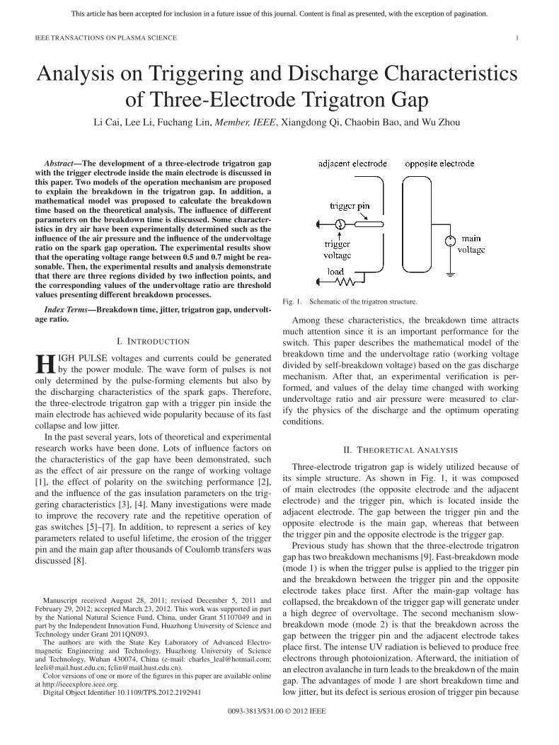
Fig. 5. Scheme of three-electrode trigatron gap (1: upper cover; 2: metallicsupports; 3: graphite electrodes: 4: tungsten triggering pin; 5: ceramic tube; 6:metal outer casing).
has much effect on trigger characteristics and lifetime. For onething, graphite electrodes are widely used for low erosion rate,high charge transfer capability, and long lifetime [17], [18]. Foranother, the tungsten trigger pin is used in this paper for its highmelting point. Moreover, many studies have investigated thatthe ceramic surface shows good performances of the emitted-pulse-charge and fast-released-charge ability, assuring to pro-vide sufficient initial electrons for the main-gap breakdown[19]. Therefore, in this paper, ceramic tube was manufactured toisolate the trigger pin from the adjacent electrode. The schemeof the trigatron gap is presented in Fig. 5.
The main gap was 0.6 cm, and the trigger gap, which isolatedthe trigger pin from the earth electrode, was 0.2 cm thick.The main-gap voltage was provided by the capacitor bank of110 μF ranging from 0 to 25 kV. The trigger voltage wasderived from a trigger generator, which had an open-circuitvoltage of approximately 15 kV.
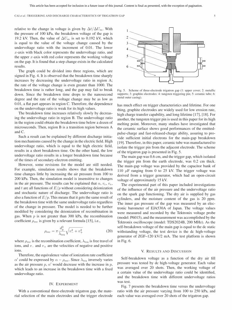
The experimental part of this paper included investigationsof the influence of the air pressure and the undervoltage ratioon the spark gap functioning. The dry air is supplied by gascylinders, and the moisture content of the gas is 20 ppm.The inner gas pressure of the gap was measured by an elec-tronic barometer of EJA530A of Japan. The voltage valueswere measured and recorded by the Tektronix voltage probe(model: P6015), and the measurement was accomplished by theTektronix oscilloscope (model: TDS2024B, 200 MHz). As theself-breakdown voltage of the main gap is equal to the dc staticwithstanding voltage, the test device is the dc high-voltagegenerator of ZGF–120 kV/2 mA. The test platform is shownin Fig. 6.
V. RESULTS AND DISCUSSION
Self-breakdown voltage as a function of the dry air fillpressure was tested by dc high-voltage generator. Each valuewas averaged over 20 shots. Then, the working voltage ofa certain value of the undervoltage ratio could be identified,and the breakdown time with different undervoltage ratioswas test.
Fig. 7 presents the breakdown time versus the undervoltageratio with the air pressure varying from 100 to 250 kPa, andeach value was averaged over 20 shots of the trigatron gap.
This article has been accepted for inclusion in a future issue of this journal. Content is final as presented, with the exception of pagination.
6 IEEE TRANSACTIONS ON PLASMA SCIENCE
Fig. 6. Test platform.
Fig. 7. Breakdown time versus undervoltage ratio.
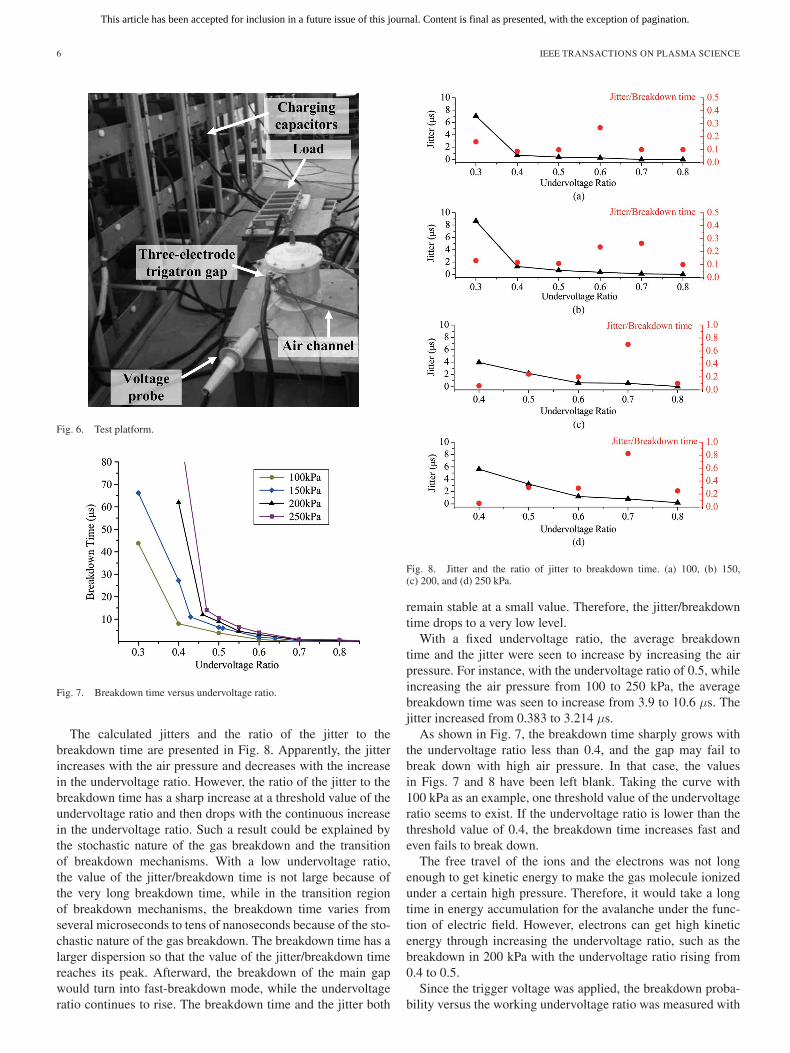
The calculated jitters and the ratio of the jitter to thebreakdown time are presented in Fig. 8. Apparently, the jitterincreases with the air pressure and decreases with the increasein the undervoltage ratio. However, the ratio of the jitter to thebreakdown time has a sharp increase at a threshold value of theundervoltage ratio and then drops with the continuous increasein the undervoltage ratio. Such a result could be explained bythe stochastic nature of the gas breakdown and the transitionof breakdown mechanisms. With a low undervoltage ratio,the value of the jitter/breakdown time is not large because ofthe very long breakdown time, while in the transition regionof breakdown mechanisms, the breakdown time varies fromseveral microseconds to tens of nanoseconds because of the sto-chastic nature of the gas breakdown. The breakdown time has alarger dispersion so that the value of the jitter/breakdown timereaches its peak. Afterward, the breakdown of the main gapwould turn into fast-breakdown mode, while the undervoltageratio continues to rise. The breakdown time and the jitter both
Fig. 8. Jitter and the ratio of jitter to breakdown time. (a) 100, (b) 150,(c) 200, and (d) 250 kPa.
remain stable at a small value. Therefore, the jitter/breakdowntime drops to a very low level.
With a fixed undervoltage ratio, the average breakdowntime and the jitter were seen to increase by increasing the airpressure. For instance, with the undervoltage ratio of 0.5, whileincreasing the air pressure from 100 to 250 kPa, the averagebreakdown time was seen to increase from 3.9 to 10.6 μs. Thejitter increased from 0.383 to 3.214 μs.
As shown in Fig. 7, the breakdown time sharply grows withthe undervoltage ratio less than 0.4, and the gap may fail tobreak down with high air pressure. In that case, the valuesin Figs. 7 and 8 have been left blank. Taking the curve with100 kPa as an example, one threshold value of the undervoltageratio seems to exist. If the undervoltage ratio is lower than thethreshold value of 0.4, the breakdown time increases fast andeven fails to break down.
The free travel of the ions and the electrons was not longenough to get kinetic energy to make the gas molecule ionizedunder a certain high pressure. Therefore, it would take a longtime in energy accumulation for the avalanche under the func-tion of electric field. However, electrons can get high kineticenergy through increasing the undervoltage ratio, such as thebreakdown in 200 kPa with the undervoltage ratio rising from0.4 to 0.5.
Since the trigger voltage was applied, the breakdown proba-bility versus the working undervoltage ratio was measured with
This article has been accepted for inclusion in a future issue of this journal. Content is final as presented, with the exception of pagination.
CAI et al.: TRIGGERING AND DISCHARGE CHARACTERISTICS OF TRIGATRON GAP 7
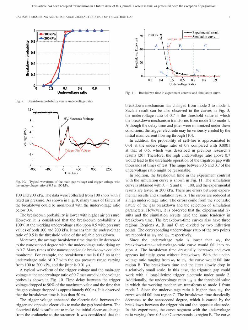
Fig. 9. Breakdown probability versus undervoltage ratio.
Fig. 10. Typical waveform of the main-gap voltage and trigger voltage withthe undervoltage ratio of 0.7 at 100 kPa.
100 and 200 kPa. The data were collected from 100 shots with afixed air pressure. As shown in Fig. 9, many times of failure ofthe breakdown could be monitored with the undervoltage ratiobelow 0.4.
The breakdown probability is lower with higher air pressure.However, it is considered that the breakdown probability is100% at the working undervoltage ratio upon 0.5 with pressurevalues of both 100 and 200 kPa. It means that the undervoltageratio of 0.5 is the threshold value of the reliable breakdown.
Moreover, the average breakdown time drastically decreasedto the nanosecond degree with the undervoltage ratio rising upto 0.7. Many times of the nanosecond-scale breakdown could bemonitored. For example, the breakdown time is 0.03 μs at theundervoltage ratio of 0.7 with the gas pressure range varyingfrom 100 to 200 kPa, and the jitter is 0.01 μs.
A typical waveform of the trigger voltage and the main-gapvoltage at the undervoltage ratio of 0.7 measured via the voltageprobes is shown in Fig. 10. Time delay between the triggervoltage dropped to 90% of the maximum value and the time thatthe gap voltage dropped is approximately 600 ns. It is observedthat the breakdown time is less than 50 ns.
The trigger voltage enhanced the electric field between thetrigger and opposite electrodes to make the gap breakdown. Theelectrical field is sufficient to make the initial electrons changefrom the avalanche to the streamer. It was considered that the
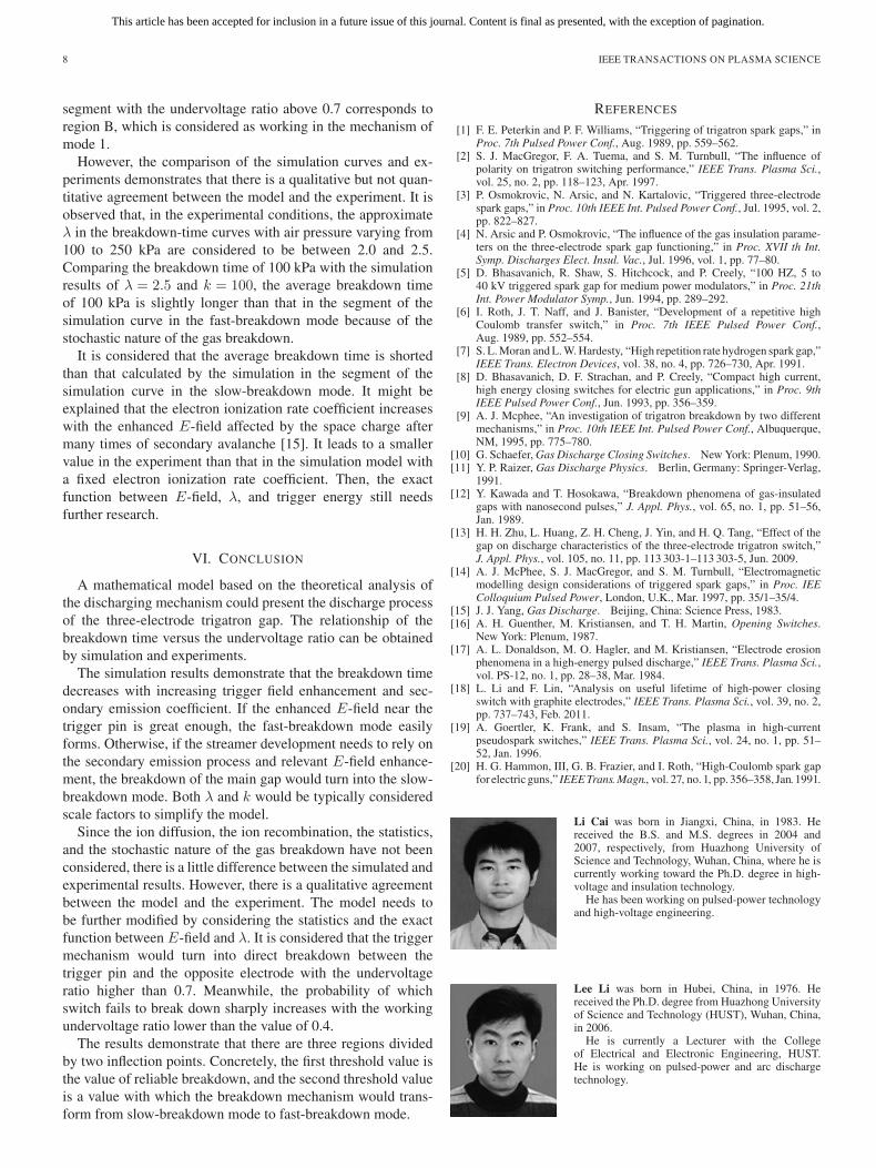
Fig. 11. Breakdown time in experiment contrast and simulation curve.
breakdown mechanism has changed from mode 2 to mode 1.Such a result can be also observed in the curves in Fig. 3;the undervoltage ratio of 0.7 is the threshold value in whichthe breakdown mechanism transforms from mode 2 to mode 1.Although the delay time and jitter were minimized under theseconditions, the trigger electrode may be seriously eroded by theinitial main current flowing through [10].
In addition, the probability of self-fire is approximated to0.01 at the undervoltage ratio of 0.7 compared with 0.0001at that of 0.6, which was described in previous research’sresults [20]. Therefore, the high undervoltage ratio above 0.7would lead to the unreliable operation of the trigatron gap withthousands of times of test. The range between 0.5 and 0.7 of theundervoltage ratio might be reasonable.
In addition, the breakdown time in the experiment contrastwith the simulation curve is shown in Fig. 11. The simulationcurve is obtained with λ = 2 and k = 100, and the experimentalresults are tested in 200 kPa. There are errors between experi-mental results and simulation results. The errors are reduced ata high undervoltage ratio. The errors come from the stochasticnature of the gas breakdown and the selection of simulationparameters. However, it is observed that the experimental re-sults and the simulation results have the same tendency inbreakdown time. The breakdown-time curves also have threeregions. Regions A, B, and C are divided by two inflectionpoints. The corresponding undervoltage ratio of the two pointsare recorded as w1 and w2, respectively.
Since the undervoltage ratio is lower than w1, thebreakdown-time–undervoltage-ratio curve would fall into re-gion A. The breakdown time drastically increases and evenappears infinitely great without breakdown. With the under-voltage ratio ranging from w1 to w2, the curve would fall intoregion B. The breakdown time and the jitter slowly drop ina relatively small scale. In this case, the trigatron gap couldwork with a long-lifetime trigger electrode under mode 2.Additionally, the undervoltage ratio w2 is the threshold valuein which the working mechanism transforms to mode 1 frommode 2. Since the undervoltage ratio is higher than w2, thecurve would fall into region C. The breakdown time drasticallydecreases to the nanosecond degree, which is caused by thebreakdown between the trigger pin and the opposite electrode.In this experiment, the curve segment with the undervoltageratio varying from 0.5 to 0.7 corresponds to region B. The curve
This article has been accepted for inclusion in a future issue of this journal. Content is final as presented, with the exception of pagination.
8 IEEE TRANSACTIONS ON PLASMA SCIENCE
segment with the undervoltage ratio above 0.7 corresponds toregion B, which is considered as working in the mechanism ofmode 1.
However, the comparison of the simulation curves and ex-periments demonstrates that there is a qualitative but not quan-titative agreement between the model and the experiment. It isobserved that, in the experimental conditions, the approximateλ in the breakdown-time curves with air pressure varying from100 to 250 kPa are considered to be between 2.0 and 2.5.Comparing the breakdown time of 100 kPa with the simulationresults of λ = 2.5 and k = 100, the average breakdown timeof 100 kPa is slightly longer than that in the segment of thesimulation curve in the fast-breakdown mode because of thestochastic nature of the gas breakdown.
It is considered that the average breakdown time is shortedthan that calculated by the simulation in the segment of thesimulation curve in the slow-breakdown mode. It might beexplained that the electron ionization rate coefficient increaseswith the enhanced E-field affected by the space charge aftermany times of secondary avalanche [15]. It leads to a smallervalue in the experiment than that in the simulation model witha fixed electron ionization rate coefficient. Then, the exactfunction between E-field, λ, and trigger energy still needsfurther research.
VI. CONCLUSION
A mathematical model based on the theoretical analysis ofthe discharging mechanism could present the discharge processof the three-electrode trigatron gap. The relationship of thebreakdown time versus the undervoltage ratio can be obtainedby simulation and experiments.
The simulation results demonstrate that the breakdown timedecreases with increasing trigger field enhancement and sec-ondary emission coefficient. If the enhanced E-field near thetrigger pin is great enough, the fast-breakdown mode easilyforms. Otherwise, if the streamer development needs to rely onthe secondary emission process and relevant E-field enhance-ment, the breakdown of the main gap would turn into the slow-breakdown mode. Both λ and k would be typically consideredscale factors to simplify the model.
Since the ion diffusion, the ion recombination, the statistics,and the stochastic nature of the gas breakdown have not beenconsidered, there is a little difference between the simulated andexperimental results. However, there is a qualitative agreementbetween the model and the experiment. The model needs tobe further modified by considering the statistics and the exactfunction between E-field and λ. It is considered that the triggermechanism would turn into direct breakdown between thetrigger pin and the opposite electrode with the undervoltageratio higher than 0.7. Meanwhile, the probability of whichswitch fails to break down sharply increases with the workingundervoltage ratio lower than the value of 0.4.
The results demonstrate that there are three regions dividedby two inflection points. Concretely, the first threshold value isthe value of reliable breakdown, and the second threshold valueis a value with which the breakdown mechanism would trans-form from slow-breakdown mode to fast-breakdown mode.
REFERENCES
[1] F. E. Peterkin and P. F. Williams, “Triggering of trigatron spark gaps,” inProc. 7th Pulsed Power Conf., Aug. 1989, pp. 559–562.
[2] S. J. MacGregor, F. A. Tuema, and S. M. Turnbull, “The influence ofpolarity on trigatron switching performance,” IEEE Trans. Plasma Sci.,vol. 25, no. 2, pp. 118–123, Apr. 1997.
[3] P. Osmokrovic, N. Arsic, and N. Kartalovic, “Triggered three-electrodespark gaps,” in Proc. 10th IEEE Int. Pulsed Power Conf., Jul. 1995, vol. 2,pp. 822–827.
[4] N. Arsic and P. Osmokrovic, “The influence of the gas insulation parame-ters on the three-electrode spark gap functioning,” in Proc. XVII th Int.Symp. Discharges Elect. Insul. Vac., Jul. 1996, vol. 1, pp. 77–80.
[5] D. Bhasavanich, R. Shaw, S. Hitchcock, and P. Creely, “100 HZ, 5 to40 kV triggered spark gap for medium power modulators,” in Proc. 21thInt. Power Modulator Symp., Jun. 1994, pp. 289–292.
[6] I. Roth, J. T. Naff, and J. Banister, “Development of a repetitive highCoulomb transfer switch,” in Proc. 7th IEEE Pulsed Power Conf.,Aug. 1989, pp. 552–554.
[7] S. L. Moran and L. W. Hardesty, “High repetition rate hydrogen spark gap,”IEEE Trans. Electron Devices, vol. 38, no. 4, pp. 726–730, Apr. 1991.
[8] D. Bhasavanich, D. F. Strachan, and P. Creely, “Compact high current,high energy closing switches for electric gun applications,” in Proc. 9thIEEE Pulsed Power Conf., Jun. 1993, pp. 356–359.
[9] A. J. Mcphee, “An investigation of trigatron breakdown by two differentmechanisms,” in Proc. 10th IEEE Int. Pulsed Power Conf., Albuquerque,NM, 1995, pp. 775–780.
[10] G. Schaefer, Gas Discharge Closing Switches. New York: Plenum, 1990.[11] Y. P. Raizer, Gas Discharge Physics. Berlin, Germany: Springer-Verlag,
1991.[12] Y. Kawada and T. Hosokawa, “Breakdown phenomena of gas-insulated
gaps with nanosecond pulses,” J. Appl. Phys., vol. 65, no. 1, pp. 51–56,Jan. 1989.
[13] H. H. Zhu, L. Huang, Z. H. Cheng, J. Yin, and H. Q. Tang, “Effect of thegap on discharge characteristics of the three-electrode trigatron switch,”J. Appl. Phys., vol. 105, no. 11, pp. 113 303-1–113 303-5, Jun. 2009.
[14] A. J. McPhee, S. J. MacGregor, and S. M. Turnbull, “Electromagneticmodelling design considerations of triggered spark gaps,” in Proc. IEEColloquium Pulsed Power, London, U.K., Mar. 1997, pp. 35/1–35/4.
[15] J. J. Yang, Gas Discharge. Beijing, China: Science Press, 1983.[16] A. H. Guenther, M. Kristiansen, and T. H. Martin, Opening Switches.
New York: Plenum, 1987.[17] A. L. Donaldson, M. O. Hagler, and M. Kristiansen, “Electrode erosion
phenomena in a high-energy pulsed discharge,” IEEE Trans. Plasma Sci.,vol. PS-12, no. 1, pp. 28–38, Mar. 1984.
[18] L. Li and F. Lin, “Analysis on useful lifetime of high-power closingswitch with graphite electrodes,” IEEE Trans. Plasma Sci., vol. 39, no. 2,pp. 737–743, Feb. 2011.
[19] A. Goertler, K. Frank, and S. Insam, “The plasma in high-currentpseudospark switches,” IEEE Trans. Plasma Sci., vol. 24, no. 1, pp. 51–52, Jan. 1996.
[20] H. G. Hammon, III, G. B. Frazier, and I. Roth, “High-Coulomb spark gapfor electric guns,” IEEE Trans. Magn., vol. 27, no. 1, pp. 356–358, Jan. 1991.
Li Cai was born in Jiangxi, China, in 1983. Hereceived the B.S. and M.S. degrees in 2004 and2007, respectively, from Huazhong University ofScience and Technology, Wuhan, China, where he iscurrently working toward the Ph.D. degree in high-voltage and insulation technology.
He has been working on pulsed-power technologyand high-voltage engineering.
Lee Li was born in Hubei, China, in 1976. Hereceived the Ph.D. degree from Huazhong Universityof Science and Technology (HUST), Wuhan, China,in 2006.
He is currently a Lecturer with the Collegeof Electrical and Electronic Engineering, HUST.He is working on pulsed-power and arc dischargetechnology.

This article has been accepted for inclusion in a future issue of this journal. Content is final as presented, with the exception of pagination.
CAI et al.: TRIGGERING AND DISCHARGE CHARACTERISTICS OF TRIGATRON GAP 9
Fuchang Lin (M’03) was born in Zhejiang, China,in 1969. He received the Ph.D. degree in electricaland electronic engineering from Huazhong Univer-sity of Science and Technology (HUST), Wuhan,China, in 1996.
He is currently a Professor with the College ofElectrical and Electronic Engineering, HUST. He hasbeen working on pulsed-power technology and high-voltage engineering.
Dr. Lin is a member of the Chinese Society forElectrical Engineering and he is a member of IEEE
Nuclear and Plasma Sciences Society, since 2007.
Xiangdong Qi was born in Hubei, China, in1984. He received the B.S. degree in 2008 fromHuazhong University of Science and Technology,Wuhan, China, where he is currently working towardthe M.S. degree in the High-Voltage EngineeringDepartment.
Chaobin Bao was born in Hubei, China, in1985. He received the B.S. degree in 2008 fromHuazhong University of Science and Technology,Wuhan, China, where he is currently working towardthe M.S. degree in the High-Voltage EngineeringDepartment.
Wu Zhou was born in Hubei, China, in 1989. He re-ceived the B.S. degree in 2011 from Huazhong Uni-versity of Science and Technology, Wuhan, China,where he is currently working toward the M.S. de-gree in the High-Voltage Engineering Department.