Embed Size (px)
Citation preview

Analysis of Traverse Beam used for the Expansion of
Steel Plant
D. Ajay Kumar1, Dr. K. S. Raghu Ram2 and Dr. B. Avinash Ben2
1Assistant Professor,
Department of Mechanical Engineering,
Vignan’s Institute of Information Technology, Visakhapatnam. 2 Associate Professor,
Department of Mechanical Engineering,
Vignan’s Institute of Information Technology,
Abstract. The Von Mises stress and principal stress calculation using Finite
Element analysis and comparison of the simulated results with the analytical
method is the aim of the present research work. Finalization of the dimensions
as per the requirement is considered. Analytical results are very closer to the
simulated results and is adopted for the application in real time and there were
no problems of the application of the designed beam. The beam assembly is
tested under full load and is successfully operating since many years.
Keywords: cross section of the traverse beam – finite element analysis –
analytical calculations- safe application for the use of lifting heavy loads.
1 Introduction
The expansion of tonnage transport of load and National Steel policy 124 MT load
carry is a hard task to carry. This expansion drive would be challenging to bring its
expanded capacity on stream. As it is known, there are several beam theories to
describe behavior of beam-type structures. The oldest and the well-known beam
theory is the Euler–Bernoulli beam theory (EBT) in which straight lines perpendicular
to the mid-plane before bending remain straight and perpendicular to the mid-plane
after bending. As a result of this assumption, traverse shear strain is neglected.
1.1 Scope of the present work
In the present work, a theoretical analysis is carried out for the design of a traverse
beam used in steel melting shop in steel plants. The traverse beam is fixed to a crane,
which is used in the steel melt shop to charge molten pig iron in a ladle to the steel
converter. The need for fixing the traverse beam to the crane arises due to the fact that
crane with a larger distance between the arms (4600 mm) is used to handle a smaller
Advanced Science and Technology Letters Vol.147 (SMART DSC-2017), pp.499-505
http://dx.doi.org/10.14257/astl.2017.147.69
ISSN: 2287-1233 ASTL Copyright © 2017 SERSC
ladle, whose width is 4300 mm. The existing old ladles are handled by the new
cranes, where the traverse beam is required for the crane.
1.2 Need for Traverse Beam
The molten pig iron is carried through ladles and poured into the LD converters.
Overhead cranes are used for carrying ladles containing molten metal. The old ladles
in steel plant have a center distance of 4300 mm. SMS-II uses new overhead cranes
with center distance of 4600mm.Thus the width of the crane (4600mm) is more than
that of the ladle (4300mm).Since the crane and ladle must be synchronous, a traverse
beam is designed, such that the ladle can be handled by the crane. By designing the
traverse beam one can eliminate making of new ladles to suit to the new cranes which
have 4600mm of center-to-center distance. This results in considerable savings in
terms of time and money.
The complete drawing details are taken from the above drawing. The traverse beam
drawing is again considered for design consideration. The design details are given in
the figure 3 with part details.
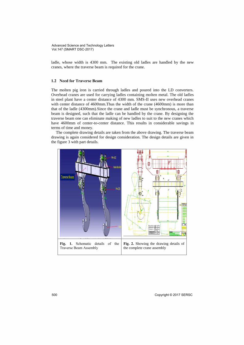
Fig. 1. Schematic details of the
Traverse Beam Assembly
Fig. 2. Showing the drawing details of
the complete crane assembly
Advanced Science and Technology Letters Vol.147 (SMART DSC-2017)
500 Copyright © 2017 SERSC
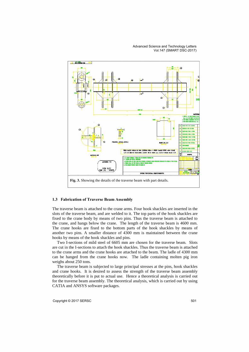
Fig. 3. Showing the details of the traverse beam with part details.
1.3 Fabrication of Traverse Beam Assembly
The traverse beam is attached to the crane arms. Four hook shackles are inserted in the
slots of the traverse beam, and are welded to it. The top parts of the hook shackles are
fixed to the crane body by means of two pins. Thus the traverse beam is attached to
the crane, and hangs below the crane. The length of the traverse beam is 4600 mm.
The crane hooks are fixed to the bottom parts of the hook shackles by means of
another two pins. A smaller distance of 4300 mm is maintained between the crane
hooks by means of the hook shackles and pins.
Two I-sections of mild steel of 6605 mm are chosen for the traverse beam. Slots
are cut in the I-sections to attach the hook shackles. Thus the traverse beam is attached
to the crane arms and the crane hooks are attached to the beam. The ladle of 4300 mm
can be hanged from the crane hooks now. The ladle containing molten pig iron
weighs about 250 tons.
The traverse beam is subjected to large principal stresses at the pins, hook shackles
and crane hooks. It is desired to assess the strength of the traverse beam assembly
theoretically before it is put to actual use. Hence a theoretical analysis is carried out
for the traverse beam assembly. The theoretical analysis, which is carried out by using
CATIA and ANSYS software packages.
Advanced Science and Technology Letters Vol.147 (SMART DSC-2017)
Copyright © 2017 SERSC 501

1.4 Geometrical model of Traverse Beam Assembly
The geometrical model of the traverse beam assembly is drawn in Catia-v5 software
as per the dimensions given in the 2-D drawing, which is presented in the above
figures. The CATIA model of the traverse beam along with the welded plates is
shown in the figure. The specifications of different components of the assembly such
as the size, material, and weight are given in the table1.
Fig. 4. Showing the design of the traverse beam using CATIA software.
Table 1. Showing the components of traverse beam.
Part
No Name of the item and Size Material QTY
Total
Weight(Kgf)
1.1 UB 610X220X113 STEEL 2 1493
1.2 PLATE 548X500X20THK STEEL 9 380
1.3 HOOK SHACKLE(SUBASSLY) STEEL 4 2680
1.4 PLATE 572X109X20THK STEEL 10 97.8
1.5 PLATE 665X288X20THK STEEL 4 112.8
1.6 PLATE 5078X700X12THK STEEL 2 836
1.7 PLATE 415X415X20THK STEEL 16 216
Advanced Science and Technology Letters Vol.147 (SMART DSC-2017)
502 Copyright © 2017 SERSC

ASSUMPTIONS
In order to compare the value of maximum principal stress in the XY- direction of
traverse beam obtained from ANSYS with a mathematical approach, the following
assumptions were made:
The geometry of the traverse beam is compared with a simply supported
beam of 4600mm.
Two point loads of each 125tons are taken centre to centre 4300mm of
the simply supported beam.
The constraints are assumed as reaction forces each of them equal to
1226KN.
Anticlockwise moments are taken positive and Clockwise moments are
taken negative.
Calculations for Principle Stress:
The principle stress is given by the formula:- 𝑀
𝐼𝑋𝑋=
σ
𝑌
Where
M= Bending moment, N-mm.
I = Area moment of inertia about neutral axis, mm4.
σ = principal stress in XY – direction, N/mm2.
Y =distance of the neutral axis from the top, mm.
For I-section beam
Fig. 5. Showing the Cross section area Traverse beam
Advanced Science and Technology Letters Vol.147 (SMART DSC-2017)
Copyright © 2017 SERSC 503

Let,
RA = reaction at A
RB = reaction at B
Taking moments about the point ‘B’
RA x 4600 = 1226250 x 4450 +
1226250 x 150
RA = 1226 KN
Now taking moments about the point
‘A’
RB x 4600 = 1226250 x 4450 +
1226250 x 150
RB = 1226 KN
Bending moment M = 183.9 x 10⁶ N-
mm
𝐘 = 315.8 mm
𝐼𝑋𝑋 = 𝐼𝑋𝑋(𝑈) + 𝐼𝑋𝑋(𝑃𝐿𝐴𝑇𝐸)
𝐼𝑋𝑋(𝑈)= 2 x 87320 x 104 = 1746 x
106 mm4
𝐼𝑋𝑋(𝑃𝐿𝐴𝑇𝐸) = 2 x [ 700𝑋123
12 +
(700 x 12 x (303.8)2 ) ] = 1550 x
106mm4
𝐼𝑋𝑋 = 3297.14 x 106 mm4
σ = principal stress in XY –
direction (in N/mm2)
σ = 𝑀𝐼𝑋𝑋𝑌
𝛔 = 17.62 N/mm2
4 Conclusions
1. A traverse beam carrying a load of 250 tons has been designed, fabricated,
tested and put into service in SMS-II Steel Plant.
2. Theoretical analysis has been carried out with the aid of CATIA and ANSYS
software to predict the stress exerted on the traverse beam. This theoretical
analysis was carried out before applying the actual load on the crane with
traverse beam.
3. Since the payload is hot molten metal and any failure of the components could
be disastrous in terms of human life, injury, and other economic costs, a factor
of safety of more than 4 was used in the design process.
4. Manual calculations of von Mises and principal stresses were also carried out.
These values compare fairly well with the ANSYS results for all components.
182 MPa with manual calculation vs. 169 MPa of ANSYS results
Advanced Science and Technology Letters Vol.147 (SMART DSC-2017)
504 Copyright © 2017 SERSC
5. Material selection was done from a set of available materials and choice was
made based on that material which exceeded the minimum stipulated factor of
safety.
References
1. “AISC Specification for structural steel buildings (AISC 360-05)”, Chicago (IL): American
Institute of Steel Construction, March 9, 2005.
2. Trahair NS, “Flexural-torsional buckling of structures”, Boca Raton. London: E&FN Spon.;
1993.
3. Timoshenko SP, Gere JM. “Theory of elastic stability”, 2nd ed.. New York: McGraw-Hill;
1961.
4. Nethercot DA, Rockey CK, “Finite element solutions for the buckling of columns and
beams”, International Journal of Mech. Sciences 1971;13:945–9.
5. Galambos TV, “Guide to stability design criteria for metal structures”, Structural Stability
Research Council. 5th ed.. New York: John Wiley & Sons; 1998.
6. Kirby PA, Nethercot DA, “Design for structural stability”, Canada, Granada. London; 1979.
7. Mohebkhah A, “The moment-gradient factor in lateral-torsional buckling on inelastic
castellated beams”, Journal of Constructional Steel Research 2004;60: 1481–94.
8. Samanta A, Kumar A, “Distortional buckling in mono symmetric I-beams”, Thin-walled
Structures (2006), Vol.44:51–6.
9. Amin Mohebkhah, “Lateral buckling resistance of inelastic I-beams under off-shear center
loading”, Thin-Walled Structures (2011)Vol. 49: 431–436. journal homepage:
www.elsevier.com/locate/tws
10. ANSYS. User’s manual, version 5.4. ANSYS Inc. 201Johnson Road, Houston, PA, 15342-
1300. 1998.
11. M. Şimşek, “Static analysis of a functionally graded beam under a uniformly distributed
load by Ritz method,” International Journal of Engineering and Applied Sciences (IJEAS)
Vol.1, Issue 3(2009)1-11
12. Reddy JN, “ Energy and variation methods in applied mechanics”, New York: John Wiley;
1984.
13. Mesut Simsek, “Vibration analysis of a functionally graded beam under a moving mass by
using different beam theories”, Composite Structures 92 (2010) 904–917,
14. D. Ajay Kumar, “Design and Analysis of traverse Beam pin in Steel Melting Shop”
Australian Journal of Basic and Applied Sciences, 9(36) December 2015, Pages: 429-436
15. J.C.Ekvall, “Static Strength Analysis of Pin-Loaded Lugs”, J. AIRCRAFT VOL. 23, NO. 5.
Advanced Science and Technology Letters Vol.147 (SMART DSC-2017)
Copyright © 2017 SERSC 505