Embed Size (px)
Citation preview

CERN - European Organization for Nuclear Research
LCD-Note-2012-016
Analysis of the behaviour of the CLIC SiD iron returnyoke during a seismic event
F. Duarte Ramos∗
∗ CERN, Switzerland
August 13, 2012
Abstract
The iron return yoke of the CLIC SiD detector concept is composed of three barrel
rings and two endcap discs which, during a seismic event, are subjected to horizon-
tal and vertical accelerations that can result in both a mechanical failure of internal
structural elements and high deformations which can lead to unwanted collisions
with other internal or external detector elements, as well as the walls of the experi-
mental cavern. This report presents the results from the analysis of the return yoke
barrel rings and endcaps under a seismic event load case.
1 Introduction
Based on the detector concepts currently under study for the International Linear Collider (ILC),
two detector concepts (CLIC ILD and CLIC SiD) have been proposed for the Compact LInear
Collider (CLIC) [1]. For comparison, both detector concepts are shown in Figure 1. Given
that, for both projects, candidate sites are located in regions with moderate to high seismic
activity (the Geneva region in Switzerland for the CLIC project and both the Fukuoka and Iwate
prefectures in Japan for the ILC project), care must be taken in order to design each detector so
that it can safely withstand the loads experienced during a typical seismic event at its location.
Given that, when compared with the CLIC ILD detector concept, the iron return yoke of
CLIC SiD is a heavier structure, the latter was chosen as the baseline for the first studies on the
seismic resistance of the CLIC detector concepts. The iron return yoke for the main solenoid of
the CLIC SiD detector concept is a 12-sided structure segmented along the beam axis in three
barrel rings (1680 tonne each) and two endcaps (3000 tonne each) as shown in Figure 2. The
segmented design of the return yoke allows the insertion and maintenance of the muon detectors
in the barrel region as well as access to the calorimeters and inner detectors inside the main
solenoid vacuum tank. Furthermore, the middle barrel ring serves as the support element for the
vacuum tank that houses the main solenoid, which, in turn, supports both the Hadron (HCAL)
and Electromagnetic (ECAL) calorimeters and the inner detectors.
This note summarizes the results from the finite element analysis of the preliminary CLIC SiD
iron return yoke design under the maximum seismic loads expected at the candidate site for the
construction of the CLIC detectors.
(a) CLIC ILD (b) CLIC SiD
Figure 1: Longitudinal cross section view of the top quadrant of the CLIC detector concepts
(from [1]).
2

Figure 2: CLIC SiD main solenoid and return yoke elements (from [1]).
2 Seismic analysis procedure
According to the French ’Decret no. 2000-892 du 13 septembre 2000 relatif a la preventiondu risque sismique’, new constructions or constructions submitted to important modifications
in seismic regions in France shall comply with the applicable seismic design requirements [2].
Therefore, and according to the ’Arrete du 22 octobre 2010’, the design of structures for earth-
quake resistance shall comply with the following standards:
• NF EN 1998-1 September 2005 - Eurocode 8: Design of structures for earthquake resis-
tance - Part 1: General rules, seismic actions and rules for buildings;
• NF EN 1998-1/NA December 2007 (National annex).
According to clause 3.1.1 of Eurocode 8 [3], ’depending on the importance class of the struc-
ture and the particular conditions of the project, ground investigations and/or geological studies
should be performed to determine the seismic action’. Therefore, in the framework of the con-
struction of the CMS and ATLAS detectors at CERN, geological and ground response analyses
have been performed by external companies [4] to determine the expected response spectra at
various depths. For the purpose of the analyses presented in this note, the response spectra
calculated for the underground cavern of CMS were used (see Figure 3).
Eurocode 8 specifies the modal response spectrum analysis, using a linear-elastic model of the
structure, as the reference method for determining the seismic effects due to a given spectrum.
This method allows for the calculation of the maximum displacements and stresses within the
structure in a given direction by performing a quadratic combination of the modal responses of
the structure multiplied by the corresponding acceleration values from the response spectrum.
3

(a) Horizontal direction
(b) Vertical direction
Figure 3: Seismic response spectra at the underground cavern of CMS - LHC Point 5, Cessy,
France (from [4]).
4

Furthermore, Eurocode 8 also specifies that ’the response of all modes of vibration contribut-
ing significantly to the global response shall be taken into account’, condition which may be
considered to be satisfied if ’either of the following can be demonstrated:
• the sum of the effective modal masses for the modes taken into account amounts to at least
90% of the total mass of the structure;
• all modes with effective modal masses greater than 5% of the total mass are taken into
account’.
Eurocode 8 also specifies the methods to be used for the modal combination procedure: a
general method using the square root of the sum of squares (SRSS) of the seismic effects (appli-
cable only if the modal responses are regarded as independent to each other), and more accurate
methods such as the Complete Quadratic Combination (CQC) method. Under the scope of the
analyses presented in this note, the CQC method was used since it is readily implemented in
ANSYS R© v13 and the added computational effort compared to the SRSS method is negligible.
3 Finite element model
Given the ”push-pull” operation of the CLIC detectors inside the underground cavern, two main
operational scenarios are foreseen: a scenario where the detector is closed and in data-taking
position and another where the detector is open and in garage position. Therefore, for the pur-
pose of the seismic analyses described in this note, both operational scenarios were considered
by looking at the behaviour of the endcaps and middle barrel ring independently (i.e. garage
position scenario) and of the complete return yoke (i.e. data-taking position scenario). For the
purpose of these analyses, the material properties shown in Table 1 were used.
Finally, the model hereafter presented was created using the following reference system:
• the Z-axis is horizontal and follows the detector axis of symmetry;
• the Y-axis is perpendicular to the Z-axis and points upward along the vertical direction;
• the X-axis completes the Cartesian coordinate system (0, X, Y, Z) and is horizontal.
Table 1: Mechanical properties of the materials used in the model
MaterialDensity Young’s Modulus
Poisson’s ratio[kg/m3] [GPa]
Structural Steel 7850 210.0 0.30
Coil Material 2546 1.0×10⁶ 0.30
Ti 5Al 2.5Sn4480 110.3 0.31
(coil tie rods)
5
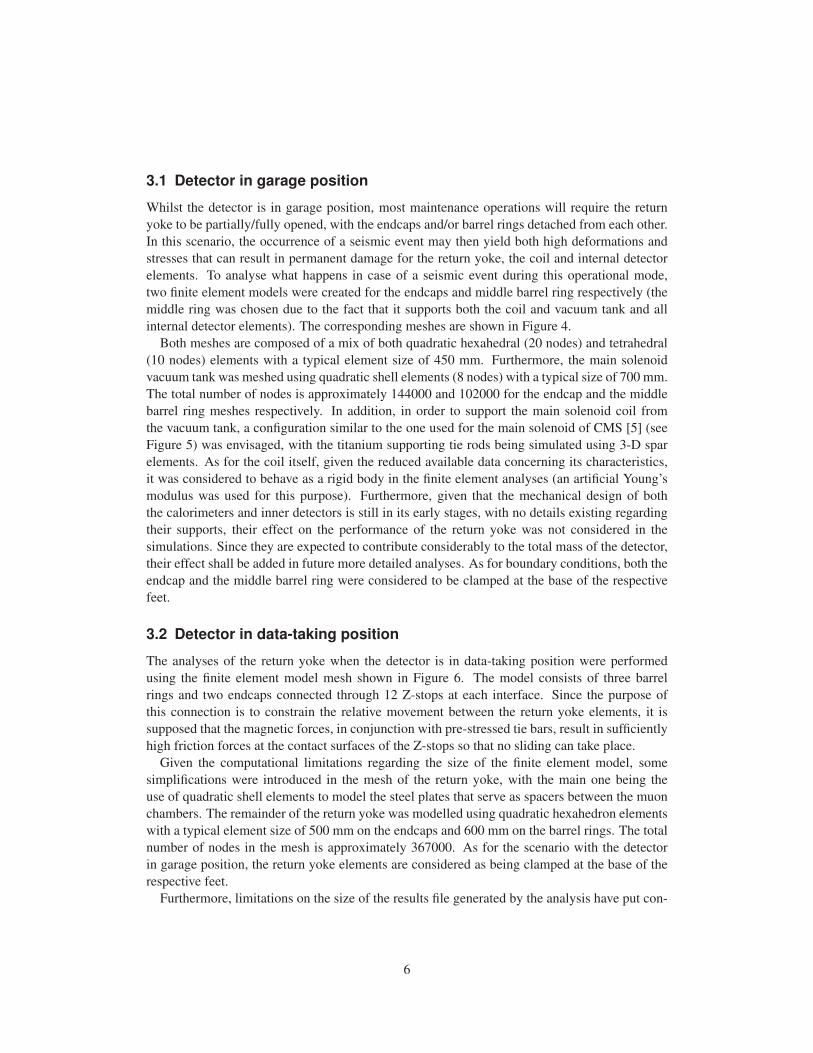
3.1 Detector in garage position
Whilst the detector is in garage position, most maintenance operations will require the return
yoke to be partially/fully opened, with the endcaps and/or barrel rings detached from each other.
In this scenario, the occurrence of a seismic event may then yield both high deformations and
stresses that can result in permanent damage for the return yoke, the coil and internal detector
elements. To analyse what happens in case of a seismic event during this operational mode,
two finite element models were created for the endcaps and middle barrel ring respectively (the
middle ring was chosen due to the fact that it supports both the coil and vacuum tank and all
internal detector elements). The corresponding meshes are shown in Figure 4.
Both meshes are composed of a mix of both quadratic hexahedral (20 nodes) and tetrahedral
(10 nodes) elements with a typical element size of 450 mm. Furthermore, the main solenoid
vacuum tank was meshed using quadratic shell elements (8 nodes) with a typical size of 700 mm.
The total number of nodes is approximately 144000 and 102000 for the endcap and the middle
barrel ring meshes respectively. In addition, in order to support the main solenoid coil from
the vacuum tank, a configuration similar to the one used for the main solenoid of CMS [5] (see
Figure 5) was envisaged, with the titanium supporting tie rods being simulated using 3-D spar
elements. As for the coil itself, given the reduced available data concerning its characteristics,
it was considered to behave as a rigid body in the finite element analyses (an artificial Young’s
modulus was used for this purpose). Furthermore, given that the mechanical design of both
the calorimeters and inner detectors is still in its early stages, with no details existing regarding
their supports, their effect on the performance of the return yoke was not considered in the
simulations. Since they are expected to contribute considerably to the total mass of the detector,
their effect shall be added in future more detailed analyses. As for boundary conditions, both the
endcap and the middle barrel ring were considered to be clamped at the base of the respective
feet.
3.2 Detector in data-taking position
The analyses of the return yoke when the detector is in data-taking position were performed
using the finite element model mesh shown in Figure 6. The model consists of three barrel
rings and two endcaps connected through 12 Z-stops at each interface. Since the purpose of
this connection is to constrain the relative movement between the return yoke elements, it is
supposed that the magnetic forces, in conjunction with pre-stressed tie bars, result in sufficiently
high friction forces at the contact surfaces of the Z-stops so that no sliding can take place.
Given the computational limitations regarding the size of the finite element model, some
simplifications were introduced in the mesh of the return yoke, with the main one being the
use of quadratic shell elements to model the steel plates that serve as spacers between the muon
chambers. The remainder of the return yoke was modelled using quadratic hexahedron elements
with a typical element size of 500 mm on the endcaps and 600 mm on the barrel rings. The total
number of nodes in the mesh is approximately 367000. As for the scenario with the detector
in garage position, the return yoke elements are considered as being clamped at the base of the
respective feet.
Furthermore, limitations on the size of the results file generated by the analysis have put con-
6

straints on the results that could be extracted from the simulations. Therefore, only displacement
information is available from the simulations of the return yoke in data-taking position.
(a) Endcap
(b) Middle barrel ring
Figure 4: Finite element model meshes for the analysis of the return yoke in garage position.
7

Figure 5: CMS coil suspension system (from [5]). In total, thirty titanium tie rods are
used to support the 225 tonne weight of the cold mass inside its vacuum tank
and react against the forces generated by potential magnetic misalignment.
Figure 6: Sectioned view of the finite element model mesh used for the analysis of the
return yoke in data-taking position.
8
4 Results
4.1 Modal analysis
The first step in a modal response spectrum analysis is the extraction of the most significant
eigenfrequencies and eigenmodes of the structure. This is done through a modal analysis proce-
dure and the results are shown next. In order achieve reasonably fast solution times (under one
day), the decision was taken to not include, at this early design stage, pre-stress effects on the
structure (due to gravity, magnetic forces, etc.). For increased accuracy, future analyses on more
detailed geometries will need to include these effects.
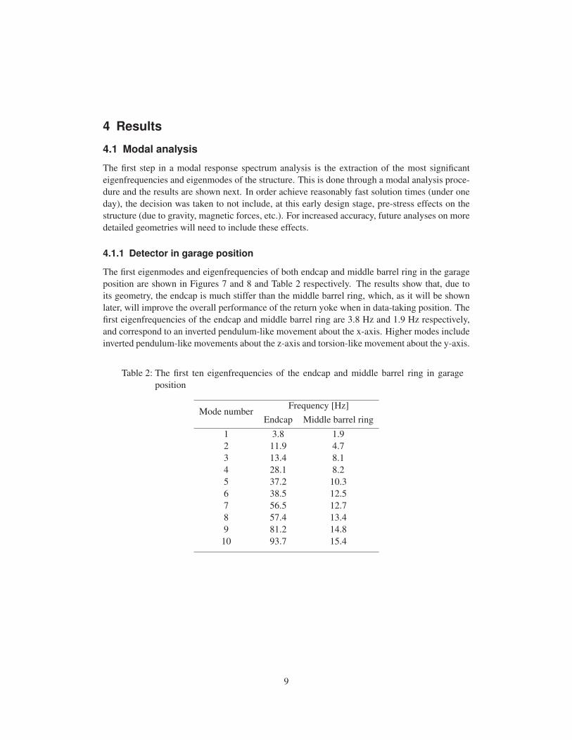
4.1.1 Detector in garage position
The first eigenmodes and eigenfrequencies of both endcap and middle barrel ring in the garage
position are shown in Figures 7 and 8 and Table 2 respectively. The results show that, due to
its geometry, the endcap is much stiffer than the middle barrel ring, which, as it will be shown
later, will improve the overall performance of the return yoke when in data-taking position. The
first eigenfrequencies of the endcap and middle barrel ring are 3.8 Hz and 1.9 Hz respectively,
and correspond to an inverted pendulum-like movement about the x-axis. Higher modes include
inverted pendulum-like movements about the z-axis and torsion-like movement about the y-axis.
Table 2: The first ten eigenfrequencies of the endcap and middle barrel ring in garage
position
Mode numberFrequency [Hz]
Endcap Middle barrel ring
1 3.8 1.9
2 11.9 4.7
3 13.4 8.1
4 28.1 8.2
5 37.2 10.3
6 38.5 12.5
7 56.5 12.7
8 57.4 13.4
9 81.2 14.8
10 93.7 15.4
9

(a) 1st mode (3.8 Hz) (b) 2nd mode (11.9 Hz)
(c) 3rd mode (13.4 Hz) (d) 4th mode (28.1 Hz)
Figure 7: The first four vibration modes of the return yoke endcap in garage position.
4.1.2 Detector in data-taking position
Concerning the scenario where the detector is in data-taking position, the lowest eigenmodes and
eigenfrequencies extracted from the modal analysis are shown in Figure 9 and Table 3 respec-
tively. Once again, the first eigenmode corresponds to an inverted oscillation about the x-axis.
However, due to the fact that the model assumes that the endcap disks and barrel rings are con-
nected to each other through the Z-stops, the value of the first eigenfrequency (6.3 Hz) is placed
between the corresponding values for the endcap and middle barrel ring in standalone mode.
Higher eingenmodes of the return yoke relate to rigid body movement of the main solenoid coil
inside its vacuum tank.
10
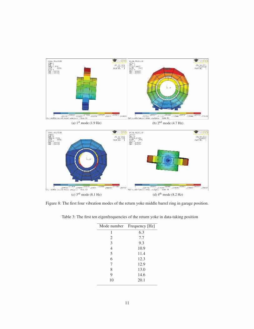
(a) 1st mode (1.9 Hz) (b) 2nd mode (4.7 Hz)
(c) 3rd mode (8.1 Hz) (d) 4th mode (8.2 Hz)
Figure 8: The first four vibration modes of the return yoke middle barrel ring in garage position.
Table 3: The first ten eigenfrequencies of the return yoke in data-taking position
Mode number Frequency [Hz]
1 6.3
2 7.7
3 9.3
4 10.9
5 11.4
6 12.3
7 12.9
8 13.0
9 14.6
10 20.1
11

(a) 1st mode (6.3 Hz) (b) 2nd mode (7.7 Hz)
(c) 3rd mode (9.3 Hz) (d) 4th mode (10.9 Hz)
Figure 9: The first four vibration modes of the return yoke in data-taking position.
4.2 Modal response spectrum analysis
Eurocode 8 requires that ’the sum of the effective modal masses for the modes taken into account
amounts to at least 90% of the total mass of the structure’. The number of modes and respective
effective modal mass ratio used in the analyses to satisfy Eurocode 8 requirements are summa-
rized in Table 4. As mentioned in §2, the response spectra shown in Figure 3 were used as an
input to the modal response spectrum analysis. Furthermore, as foreseen in clauses 4.3.3.5.1(2)
and 4.3.3.5.2(4) of Eurocode 8, the SRSS method was used to determine the combined effect of
the seismic actions in the three Cartesian directions.
12

Table 4: Number of eigenmodes used in the simulations to meet Eurocode 8 specifications
Geometry DirectionNumber of modes Effective modal mass
used (in % of total mass)
Endcap
X 6 99.7
Y 6 99.3
Z 6 97.3
Middle barrel ring
X 15 97.1
Y 15 96.7
Z 15 91.0
Return yoke
X 55 96.3
Y 65 96.2
Z 14 94.3
4.2.1 Detector in garage position
The results obtained from the modal response spectrum analysis of both the endcap (Figure 10)
and middle barrel ring (Figure 11) in garage position show relatively low maximum deformation
values (5.6 mm and 23 mm, respectively). However, the maximum stress levels at the feet are
close to the yield strength of conventional structural steels (235-450 MPa). Therefore, in order
to minimize the risk of permanent deformations after a seismic event, a redesign of the feet’s
geometry and the way their are connected to the endcaps and barrel rings is recommended at a
later design stage.
(a) Deformation (b) von Mises equivalent stress
Figure 10: Modal response spectrum analysis results for the endcap in garage position. The
maximum deformation is 5.6 mm and the corresponding von Mises equivalent stress
is 172 MPa.
13
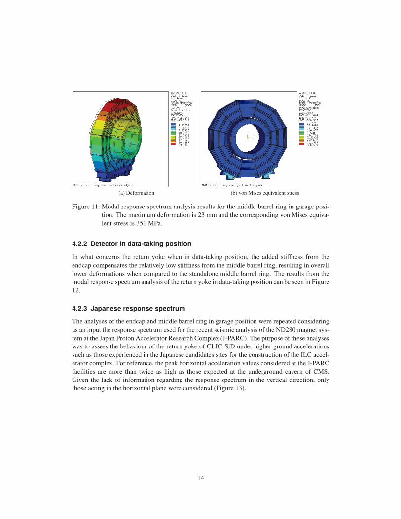
(a) Deformation (b) von Mises equivalent stress
Figure 11: Modal response spectrum analysis results for the middle barrel ring in garage posi-
tion. The maximum deformation is 23 mm and the corresponding von Mises equiva-
lent stress is 351 MPa.
4.2.2 Detector in data-taking position
In what concerns the return yoke when in data-taking position, the added stiffness from the
endcap compensates the relatively low stiffness from the middle barrel ring, resulting in overall
lower deformations when compared to the standalone middle barrel ring. The results from the
modal response spectrum analysis of the return yoke in data-taking position can be seen in Figure
12.
4.2.3 Japanese response spectrum
The analyses of the endcap and middle barrel ring in garage position were repeated considering
as an input the response spectrum used for the recent seismic analysis of the ND280 magnet sys-
tem at the Japan Proton Accelerator Research Complex (J-PARC). The purpose of these analyses
was to assess the behaviour of the return yoke of CLIC SiD under higher ground accelerations
such as those experienced in the Japanese candidates sites for the construction of the ILC accel-
erator complex. For reference, the peak horizontal acceleration values considered at the J-PARC
facilities are more than twice as high as those expected at the underground cavern of CMS.
Given the lack of information regarding the response spectrum in the vertical direction, only
those acting in the horizontal plane were considered (Figure 13).
14
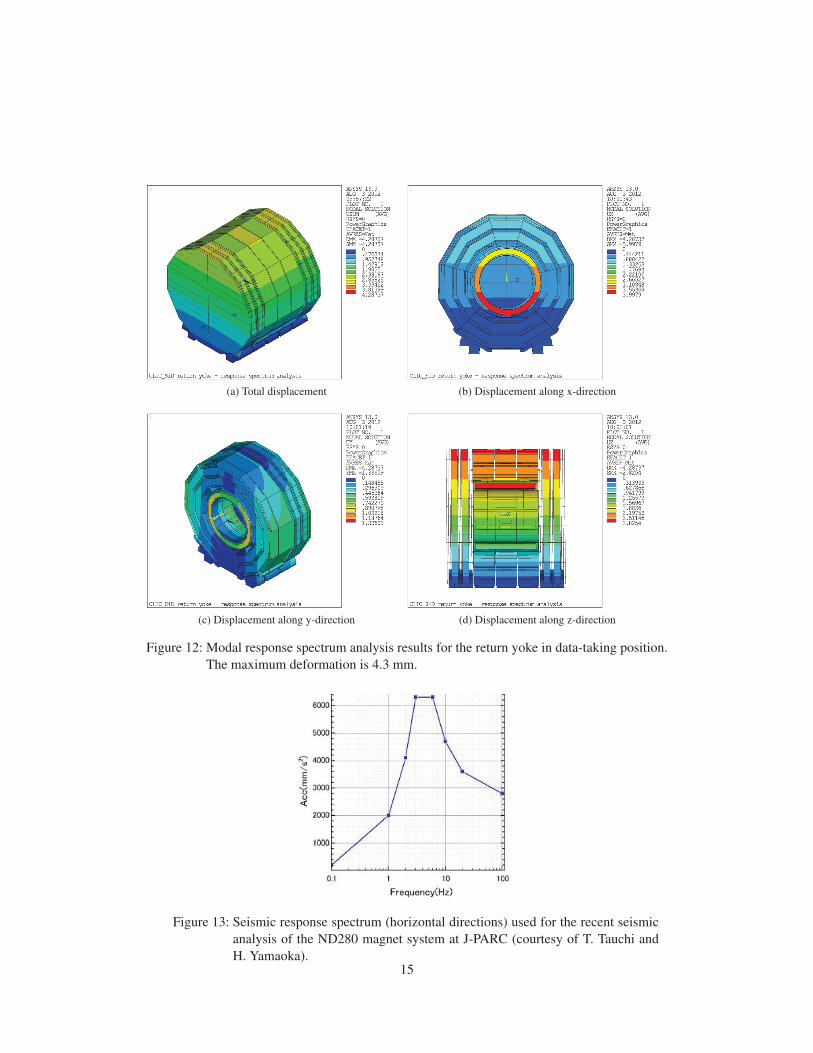
(a) Total displacement (b) Displacement along x-direction
(c) Displacement along y-direction (d) Displacement along z-direction
Figure 12: Modal response spectrum analysis results for the return yoke in data-taking position.
The maximum deformation is 4.3 mm.
Figure 13: Seismic response spectrum (horizontal directions) used for the recent seismic
analysis of the ND280 magnet system at J-PARC (courtesy of T. Tauchi and
H. Yamaoka).15
(a) Endcap displacement (b) Endcap stress
(c) Middle barrel ring displacement (d) Middle barrel ring stress
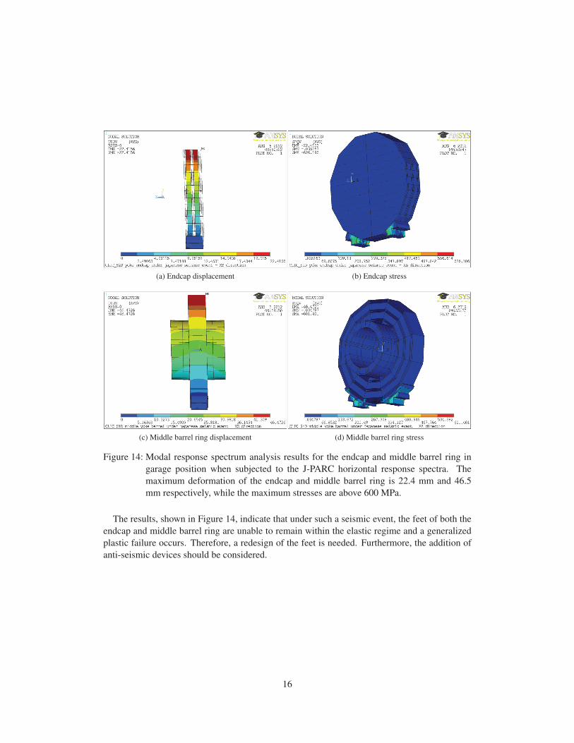
Figure 14: Modal response spectrum analysis results for the endcap and middle barrel ring in
garage position when subjected to the J-PARC horizontal response spectra. The
maximum deformation of the endcap and middle barrel ring is 22.4 mm and 46.5
mm respectively, while the maximum stresses are above 600 MPa.
The results, shown in Figure 14, indicate that under such a seismic event, the feet of both the
endcap and middle barrel ring are unable to remain within the elastic regime and a generalized
plastic failure occurs. Therefore, a redesign of the feet is needed. Furthermore, the addition of
anti-seismic devices should be considered.
16

5 Conclusion
This document presents the results from the analysis of the performance of the preliminary
CLIC SiD iron return yoke geometry under a seismic event following Eurocode 8 guidelines.
The analysis considers the behaviour of the return yoke in both its closed and opened config-
urations. The results show that in both configurations the return yoke exhibits an overall good
resistance to a typical seismic event at a CERN underground location (CMS cavern). Neverthe-
less a redesign of the supporting feet, taking into account integration constraints, is advisable.
Although both stress and deformation levels in the return yoke are within safe values, the
calorimeters and inner detectors sitting inside the vacuum tank free bore are likely to be the
components that will drive the need for additional seismic isolation measures and devices.
As for the possibility of placing such detector in a high seismicity region, a redesign of the
supporting feet is imperative as well as the consideration of additional seismic isolation devices.
The remarks made before concerning the calorimeters and inner detectors are also valid in this
scenario.
Once the mechanical design of the CLIC SiD detector concept is more advanced, the analyses
presented before should be repeated on more detailed geometries, with special attention being
paid to the assessment of the integrity of the connections between components as well as of
the calorimeters and inner detectors. Furthermore, nonlinear time-domain based analyses will
be needed to investigate the possibility of lift-off, topple over and sliding of the return yoke
elements under a seismic event.
References
[1] L. Linssen, A. Miyamoto, M. Stanitzki, and H. Weerts. Physics and Detectors at CLIC:
CLIC Conceptual Design Report. (CERN-2012-003), 2012.
[2] J. C. Batista Lopes. Seismic action at CERN, 2011. EDMS no. 1158454.
[3] NF EN 1998-1 - Eurocode 8: Design of structures for earthquake resistance, 2005.
[4] G. Benincasa and R. Schmidt. Sesmic design spectra for ATLAS and CMS, 2000. EDMS
no. 109545.
[5] B. Levesy, H. Gerwig, F. Kircher, and M. Reytier. Design and test of the titanium alloy tie
rods for the CMS coil suspension system. Applied Superconductivity, IEEE Transactionson, vol. 12(1) pp. 403 – 406, 2002.
17