Embed Size (px)
Citation preview

Analysis of the behaviour of fibre composite transom decks for railway bridges ii
University of Southern Queensland
Faculty of Engineering and Surveying
Analysis of the behaviour of composite transom decks for railway Bridges
A dissertation submitted by:
Mr Scott Walker
Supervised by
Dr Allan Manalo
In fulfilment of the requirements of
Engineering research project

S Walker iii
ABSTRACT Hardwood has been the preferred material for railway sleepers and maintenance work on existing
timber sleeper track continues to be provided by hardwoods. Worldwide, there are more than 35
million timber sleepers required to maintain the track quality into a specified level of service. In
Australia alone, railway lines require in excess of 2.5 million timber sleepers per year for railway
maintenance. Over the past decade, it has been increasingly difficult to get good quality and large
section of hardwood timber in quantities to keep up with demand especially in maintaining existing
timber-sleeper railway lines. This trend is set to continue and will become critical within the
foreseeable future, hence there is an urgent need to develop a sleeper product made from
renewable resources.
Research and development has now focused on composite materials as the key performance
characteristics of timber sleepers can be simulated using this material. Railway sleepers from
composite materials showed the highest potential among the alternative sleeper materials for
replacement of timber sleepers in the existing railway lines including transoms. Transoms are large
sleepers used on railway bridges to transfer the loads from the rails to the bridge girders. In general
there is no ballast present and the transoms have to transfer all the loads. The loads on the
transoms depend on the position of the rails relative to the bridge beams. In Australia, the rails and
the support beams are generally off-set which creates significant bending moments and shear forces
in the transom. Thus, careful consideration is needed to account for the off-set of the rails in the
design of the railway transom.
This project will investigate the potential use and analyse the suitability of composite sandwich
structures in the development of transom decks for use on railway bridges. Finite element modelling
and simulation using strand7 finite element software will be implemented to investigate the overall
performance of the composite sandwich transom decks under the wheel loading due to the passing
train. Conclusions on the suitability composite sandwich structures for use as transom decking is
drawn, orientations and laminations determined as well as recommendations for future research
suggested.
Analysis of the behaviour of fibre composite transom decks for railway bridges iv
University of Southern Queensland
Faculty of Health, Engineering and Sciences
ENG4111/ENG4112 Research Project
Limitations of Use
The Council of the University of Southern Queensland, its Faculty of Health, Engineering & Sciences,
and the staff of the University of Southern Queensland, do not accept any responsibility for the
truth, accuracy or completeness of material contained within or associated with this dissertation.
Persons using all or any part of this material do so at their own risk, and not at the risk of the Council
of the University of Southern Queensland, its Faculty of Health, Engineering & Sciences or the staff
of the University of Southern Queensland.
This dissertation reports an educational exercise and has no purpose or validity beyond this exercise.
The sole purpose of the course pair entitled “Research Project” is to contribute to the overall
education within the student’s chosen degree program. This document, the associated hardware,
software, drawings, and other material set out in the associated appendices should not be used for
any other purpose: if they are so used, it is entirely at the risk of the user.

S Walker v
Disclaimer
I certify that the ideas, experimental work, results, analyses, software and conclusions reported in
this dissertation are entirely my own effort, except where otherwise acknowledged. I also certify
that the work is original and has not been previously submitted for any other award, except where
otherwise acknowledged.

Analysis of the behaviour of fibre composite transom decks for railway bridges vi
Acknowledgements
I would like to thank my supervisor Dr Allan Manalo for his guidance throughout the course of my
project. I would also like to thank my wife for reminding me to eat during the writing of my
dissertation and providing support and encouragement throughout the whole process.

S Walker vii
ABSTRACT iii
Notations xi
Chapter 1 - Introduction 1
1. Introduction 1 1.1. Introduction 1 1.2. The Problem 3 1.3. Research Objectives 4 1.4. Conclusions 4
Chapter 2 - Literature Review 6 2. Review of literature on decking/sleeper Material 6
2.1. General 6 2.2. Timber 6
2.2.1. Hardwood 8 2.2.2. Softwood 8 2.2.3. Plywood 8
2.3. Concrete 8 2.4. Steel 9 2.5. Need for new type of sleeper 9 2.6. Composite sandwich structure 9
2.6.1. Properties 10 2.6.2. Applications 10
2.7. Conclusions 10
Chapter 3 - Methodology 11 3. Methodology 11
3.1. Track design 11 3.1.1. Rail curvature 11 3.1.2. Gauge 11 3.1.3. Cross Ties 11
3.2. Track Loads 11 3.2.1. 300LA track Load 11
3.3. Bending Moment and Shear 14 3.3.1. Bending Moment 14 3.3.2. Shear 14 3.3.3. Conclusion 14
Chapter 4 - Bridge Transoms 16 4. Fibre Composite transom dimensions 16
4.1. Single Sandwich 17 4.1.1. Introduction 17 4.1.2. Design for Bending 18 4.1.3. Design for shear 21 4.1.4. Flatwise Results 22
4.2. Edge single sandwich 22 4.2.1. Design for bending 22 4.2.2. Design for Shear 23 4.2.3. Edgewise Results 24
4.3. Multiple Flatwise Sandwich 24 4.3.1. Multiple Flatwise Sandwich Design for Bending 25 4.3.2. Multiple Flatwise Sandwich Design for Shear 27

Analysis of the behaviour of fibre composite transom decks for railway bridges viii
4.3.3. Multiple Flatwise Sandwich Conclusion 27 4.4. Multiple Edge Sandwich Design for Bending 29
4.4.1. Multiple Sandwich Edge Layout Design for Shear 30 4.4.2. Multiple Sandwich Edge Layout Conclusion 30
4.5. Combination Layout 30 4.5.1. Combination design for bending 31 4.5.2. Combination design for shear 31 4.5.3. Combination design conclusion 32
4.6. Conclusions 33
Chapter 5 - Transom Panel 34 5. Rail Loads for Bridge Deck Panel 34
5.1. Analysis in bending/Shear 35 5.1.1. Multiple Flat Sandwiches 35 5.1.2. Multiple Edge Sandwiches 36 5.1.3. Multiple Combination Panel 36
5.2. Analysis in Shear 37 5.3. Conclusions 37
Chapter 6 - Finite Element Analysis 38 6. Finite Element Analysis 38
6.1. Finite Element Models 38 6.2. Modelling Results 41
6.2.1. Transom Beams 290 w x 209 h 41 6.2.2. Panels 1200 w x 209 h 44
Chapter 7 - Conclusions 47 7. Conclusions 47
7.1. Summary 47 7.2. Major Conclusions 47 7.3. Application to railway transom decking 47 7.4. Future recommended research 48
References 49
Appendices 52 A. Flexural Stiffness flatwise and edgewise 52

S Walker ix
Figure 1: Open Deck Bridge (Yong, 2009) ............................................................................................... 1
Figure 2: Ballast Deck (Crouch Engineering, 2014) ................................................................................. 1
Figure 3: Rail Offset Example .................................................................................................................. 2
Figure 4: Example Transom Decking ....................................................................................................... 3
Figure 5: Failure due to fungal attack (Ferdous & Manalo 2014) ........................................................... 7
Figure 6: End Split (Ferdous & Manalo 2014) ......................................................................................... 7
Figure 7: Termite affected wood ............................................................................................................ 7
Figure 8: 300LA load system (AS 5100) ................................................................................................. 12
Figure 9: Bending Moment Diagram ..................................................................................................... 15
Figure 10: Shear Force Diagram ............................................................................................................ 15
Figure 11: Panel Layout and Orientations ............................................................................................ 16
Figure 12: Positive Bending ................................................................................................................... 17
Figure 13: Flat Sandwich Moduli ........................................................................................................... 19
Figure 14: Edgewise layout ................................................................................................................... 22
Figure 15: Combination Layout ............................................................................................................. 30
Figure 16: Proposed Panel Layout ........................................................................................................ 34
Figure 17: F.E. Model for specimen BS1F ............................................................................................. 39
Figure 18: F.E. Model for Specimen BM4F ............................................................................................ 39
Figure 19: F.E. Model for Specimen BM4E ............................................................................................ 39
Figure 20: F.E. Model for Specimen BM4C ........................................................................................... 40
Figure 21: F.E. Model for Specimen PM10F .......................................................................................... 40
Figure 22: F.E. Model for Specimen PM10E .......................................................................................... 40
Figure 23: F.E. Model for specimen PM10C .......................................................................................... 41
Figure 24: F.E. Model BS1F Shear ......................................................................................................... 41
Figure 25: F.E. Model BS1F Stress ......................................................................................................... 41
Figure 26: F.E. Model BM4F Shear ........................................................................................................ 42
Figure 27: F.E.M. BM4F Axial Stress ...................................................................................................... 42
Figure 28: F.E. Model BM4E Shear ........................................................................................................ 42
Figure 29: F.E. Model BM4E Axial Stress ............................................................................................... 43
Figure 30: F.E. Model BM4C Shear ....................................................................................................... 43
Figure 31: F.E. Model BM4C Axial Stress .............................................................................................. 43
Figure 32: F.E. Model PM10F Shear ...................................................................................................... 44
Figure 33: F.E. Model PM10F Axial Stress ............................................................................................. 44
Figure 34: F.E. Model PM10E Shear ...................................................................................................... 45
Figure 35: F.E. Model PM10E Axial Stress ............................................................................................. 45
Figure 36: F.E. Model PM10C Shear ...................................................................................................... 46
Figure 37: F.E. Model PM10C Axial Stress ............................................................................................ 46

Analysis of the behaviour of fibre composite transom decks for railway bridges x
Table 1: Values of Alpha (AS5100) ........................................................................................................ 13
Table 2: Transom Spacing (Railcorp 2015) ............................................................................................ 13
Table 3: Load Factors (AS5100) ............................................................................................................. 14
Table 4: Properties of Core and Skin of Sandwich ................................................................................ 17
Table 5: Single Sandwich Flatwise......................................................................................................... 22
Table 6: Single Sandwich Edgewise ....................................................................................................... 24
Table 7: Multiple Flatwise Layout ......................................................................................................... 26
Table 8: 300mm High Multiple Flat Sandwich ...................................................................................... 27
Table 9: 350 mm Wide Multiple Flat Sandwich .................................................................................... 28
Table 10: Multiple Edgewise layout ...................................................................................................... 29
Table 11: Combination Layout part 1 ................................................................................................... 32
Table 12: Multiple Flatwise Layout Panel ............................................................................................. 35
Table 13: Edgewise Multiple Sandwich Layout panel ........................................................................... 36
Table 14: Combination Layout Panel .................................................................................................... 36
Table 15: F.E. model for Sandwich Beam .............................................................................................. 38

S Walker xi
Notations
Notation Description
b Width of the beam (mm)
C Thickness of the Core (mm)
d Distance between skin centroids (mm)
D Thickness of the overall sandwich (mm)
Ec Young’s Modulus of the Core
EI Flexural Stiffness
Es Young’s Modulus of the Skin
I Moment of inertia of the cross-section mm4
M Bending moment at a given cross section N.mm
Ng Ratio of shear modulus (Skin to core)
Pc Ultimate Shear Force
PE Shear force edge orientation
PF Shear Force flat orientation
Y Distance from the neutral plane to a particular fibre, in mm
σ Bending stress in Mpa
𝜎𝑐 Stress in the Core
𝜎𝑠 Stress in the Skin
𝜏𝑐 Shear force in the Core (kN)
𝜏𝑠 Shear force in the Skin (kN)

Chapter 1 - Introduction
S Walker 1
Chapter 1 - Introduction
1. Introduction “Not too long ago the problems of cross ties were solely in terms of the wood tie” (Hay 1982)
1.1. Introduction
Railroad bridges are predominantly simple-span structures (Duan 1999). This simple-span structure
has a deck which provides the support structure for the rails supported by girders and usually a
trestle type footing. Rail bridge decks are usually one of two different designs those being open deck
(Figure 1), or ballast deck (Figure 2).
Figure 1: Open Deck Bridge (Yong, 2009)
Figure 2: Ballast Deck (Crouch Engineering, 2014)

Analysis of the behaviour of fibre composite transom decks for railway bridges 2
Open deck bridge designs have the cross ties directly supported by the bridge girders. Due to the
much lower dead loads of open deck bridge design, they are the most common form of railway
bridge deck. Open deck rail bridges, however, transfer more of the dynamic load from the rail live
load into the supporting structure than ballast decks (Duan 1999).
Figure 3: Rail Offset Example
In the design of open deck bridges, the rail is often at an offset to the bridge girders. This is done so
that any re-alignment of the rail may be performed without the need to move the girders (Esveld
2001). Wider girders also allow for better stability (in relation to wind loading) of the bridge and
offsetting the rails allows the girders to be positioned wider than the gauge and thus better handle
wind loads(Duan 1999). The effect of having the rails offset to the support girders is that it creates
both a bending moment and shear in the cross ties. The bending moment and shear requires bridge
cross ties to be of greater dimensions than those of standard railway sleepers as standard sleepers
are fully supported along their length and are not required to carry these types of loads. The bridge
cross ties are still placed at similar spacing to standard railway sleepers, namely 600 mm centres and
the rail offset has a maximum limit of 250mm, but usually much less (Hay 1982).
This report concentrates on another less-common type of open bridge deck called transom decking
Figure 4. Transom decking differs to cross ties by the simple fact that it presents as that of a uniform
level surface similar to that of a walking bridge. For a bridge with transom decking, the rails are
directly fixed to this uniform gapless surface and the panels. The decking perform the role of cross
ties, that of keeping the rails at the set gauge, and transferring the rail loads to the substructure of
the bridge (Hay 1982). Rails are directly fixed at the same spacing of 600mm, usually by clamp plates
bolted through the decking.

Chapter 1 - Introduction
S Walker 3
The major advantage of this kind of bridge decking is safety. During construction and maintenance
the bridge presents with a uniform surface safe for walking on which eliminates the risk of falling
through or tripping. Other advantages of transom decking over the normal cross ties are:
The transom deck provides a barrier for both the supporting structure beneath the deck and
anything else below on the ground from objects falling off the passing train.
The decking also protects the supporting structure of the bridge from sun and moisture.
The transom decking also provides a suitable walking surface for pedestrian crossing if
required.
Figure 4: Example Transom Decking
1.2. The Problem
Existing bridge cross ties are made predominantly from hardwood. Existing wooden cross ties have
the desirable material property combination of flexibility and workability not found in other
materials (Hibbeler, 2004). The drawback of hard wood is that it has a limited life span of
approximately 20 years if chemical treatment (Profillidis 1995). Without treatment, the life
expectancy can be greatly reduced by natural factors, which in Queensland, is predominantly fungal
decay (Hagaman 1992), but also includes insect attack. At the end of the cross-tie life cycle the
transom must be replaced which is where this project is positioned.
Hard wood of suitable size for rail sleepers is becoming rarer and more expensive as the amount of
hardwood available for production is reduced due to both government regulation and
environmental pressure (Mcleod 1991). Due to Rail Bridge cross ties being nearly 100% larger than
normal cross ties, sources of larger hardwood trees must be secured which increases the cost
further. Annually, the rail industry spends over 35% of its annual budget on maintenance of sleepers
(Yun 2003), with bridge transoms accounting for a significant percentage of that.
This has opened the door for development of alternative and renewable materials, previously
considered too expensive. Currently, rail bridge decking is constructed from plywood developed
specifically for the purpose and as a direct replacement for current bridge cross-ties (B4B, 2011).
Plywood consists of glued laminations of thin wood veneers at 90 degree orientations. Plywood
presents a viable option as bridge decking, but suffers from the similar problems to hardwood in
that it is a natural product that suffers from natural degradation.
This project seeks to determine the suitability of a particular fibre composite sandwich material to
act as bridge transom decking.

Analysis of the behaviour of fibre composite transom decks for railway bridges 4
This project will undertake the following:
Research the existing materials used for rail bridge decks including material strength
characteristics and material orientation.
Identify the advantages and disadvantages of existing materials specifically looking at the
Australian rail bridge scenario.
Identify the different parameters that affect the behaviour of transoms, including loading
cases, railway geometry, and type of transom.
Analyse the effects of different design parameters on the overall behaviour of transom
decks using the Strand 7 finite element simulation software.
Investigate the suitability of a proposed structural composite sandwich for transom decks
through finite element simulation and analysis.
Investigation of the best arrangement for the sandwich panels in the transom deck that will
result in optimal structural performance.
1.3. Research Objectives
The aim of this study is to investigate the behaviour of a fibre composite sandwich structure and
determine its potential application for replacement of railway timber decking.
The main objectives of the study are the following:
Characterise the mechanical behaviour of existing bridge decking
Evaluate the mechanical behaviour of an individual fibre composite sandwich structure in
the flatwise and in the edgewise positions, theoretically, and by finite element modelling
Investigate the flexural and shear behaviour of the composite sandwich structures
numerically and via finite element modelling
Determine the suitability of the fibre composite sandwich for rail bridge decking
1.4. Conclusions
This thesis is divided into chapters which cover the research objectives in a structured way.
Chapter 1 is an introduction and outlines the objectives of this study.
Chapter 2 provides a literature review on existing materials for railway transom decking, dealing
with the following:
Suitability to rail decking using Australian construction techniques
The materials consequent issues for use as a railway bridge decking.
The practicality of composite sandwich structures becoming a suitable alternative for railway
bridge decking
Chapter 3 conducts an investigation on the behaviour of bridge cross-ties in a normal railway bridge,
including investigation of rail loads to define the requirements for the alternative fibre composite
sleepers.
Chapter 4 is concerned with the investigation of the mechanical properties of the fibre composite
sandwich panel for its effective use as a replacement for individual bridge cross ties in both flatwise
and edgewise positions for single and multiple sandwich laminations.

Chapter 1 - Introduction
S Walker 5
Chapter 5 investigates the flexural and shear behaviour of the composite sandwich structure as a
decking panel via numerical investigations.
Chapter 6 presents the finite element modelling for beams and panels
Chapter 7 present the conclusions found in the research and recommendations for future work.

Analysis of the behaviour of fibre composite transom decks for railway bridges 6
Chapter 2 - Literature Review
2. Review of literature on decking/sleeper Material
2.1. General
This chapter provides general information about the properties of current railway bridge cross ties
and transom decks for railway bridges including the potential use as deck panelling.
2.2. Timber
Timber has been the main stay of railway sleepers since the inception of rail. In Australia the
replacement of wooden rail components accounts for over 280 000 m3 of timber (Griffin et al. 2014).
Timber has the desirable natural properties of flexibility and workability. The workability allows
sleepers to be repaired, altered or replaced without the need for specialised skills or equipment,
thereby reducing down time when performing maintenance. The flexibility of wood allows it to flex
repeatedly with little fatigue (Manalo 2011). The flexibility of wood also acts as a dampener for
vibration transfer from the steel wheels on the rail to the bridge support structure causing audible
noise. Noise from a passing train can be amplified by the bridge structure and it is important to take
this into consideration especially in urban areas. The reduction in noise levels with effective
dampening can be as much as 10db, therefore, the natural characteristic of flexibility found in wood
is important (Poisson & Margiocchi 2006).
A major disadvantage of wood, from a structural point of view, is its susceptibility to fire. Fire is one
of the most severe hazards that any built infrastructure may face. The increase in transported
hazardous materials such as flammable materials, spontaneously combustible materials as well as
corrosive materials is often considered safest when transported by rail (Garlock et al. 2012). The
potential for major infrastructure cost due to a bridge fire caused by a transport accident, or even
lightning strike is a reality.
The other main disadvantage of wood is that it has a limited life span due to deterioration caused by
the natural processes of microbiological decay, insect attack, as well as mechanical fatigue (Adams
1991). Micro-organisms thrive in the right environment and the combination of bridge transoms
made of wood with its natural bark defence removed, exposed to the weather, which introduces
moisture and oxygen, provides an excellent habitat for these micro-organisms to thrive. The most
serious kind of microbiological decay is caused by fungus, as it causes rapid structural failure. The
most destructive and common form is brown rot (Monrroy et al. 2011). An example of failure due to
fungal attack is shown in Figure 5. Brown rot feeds on the cellulose in the wood which comprises
nearly 50% of the timber structure, without cellulose the wood has no ability to carry load (Xu &
Goodell 2001). Fungal attack accounts for more than 50% of all railway sleeper failures (Ferdous &
Manalo 2014).

Chapter 2 - Literature Review
S Walker 7
Figure 5: Failure due to fungal attack (Ferdous & Manalo 2014)
The next most common form of failure for wood is splitting, which accounts for around 10% of
railway sleeper failures. The natural process of timber swelling and shrinking when the timber
equilibrates to the surrounding moisture conditions can cause horizontal splitting in the wood which
seriously reduces the woods strength (Akbiyik, Lamanna & Hale 2007). End splitting is a combination
of swelling and shrinking along with transverse shear loading of the timber causing the planes of
flexure of timber fibres to move and become separated. End splitting is shown below in Figure 6.
Figure 6: End Split (Ferdous & Manalo 2014)
The other major cause of sleeper failure is insect attack, in particular termites. Termites account for
7% of sleeper failure (Ferdous & Manalo). Termites feed on the cellulose in the wood, and as with
fungus attack, without cellulose the wood has no ability to carry loads. An example of the extent
that termite can attack affected wood is shown below in Figure 7.
Figure 7: Termite affected wood

Analysis of the behaviour of fibre composite transom decks for railway bridges 8
2.2.1. Hardwood
Hardwood used for transoms, on average, have a lifespan of 20 years (Ferdous & Manalo 2014) and
when the transom can no longer carry a load it is required to have maintenance to either renew or
replace it. The life span of 20 years has largely come about through the use of Creosote to pressure
treat the wood and help prevent fungal and insect attack (Bolin, Christopher & Stephen 2013).
Creosote is a mid-heavy distillate of coal tar which contains large amounts of polycyclic aromatic
hydrocarbons (PAH) and is widely used as a wood preservative (Ikarashi, Kaniwa & Tsuchiya 2005).
Although the use of creosote has improved the lifespan of hardwood sleepers, its use has presented
some problems when it comes to the disposal of expired sleepers. The EPA has recommended that
creosote treated sleepers not come into direct contact with skin, not be used for firewood, and not
be used for garden edging due to some PAH’s being a potential human carcinogen (Ikarashi, Kaniwa
& Tsuchiya 2005). To avoid end splitting in bridge transoms, the use of cross ties with a greater width
and depth is used which reduces the overall transverse shear and the likelihood of failure due to end
splitting. The use as transom decking is limited due to wood being unavailable in sizes suitable for
use as a panel.
2.2.2. Softwood
Softwood of sufficient cross section has been used for rail cross ties, but due to difficulty of
penetrating the wood with chemical treatments tends to have a smaller life span than hardwood
(Vinden, Torgovnikov & Hann 2011). Hardwood transmits sap via its cellular structure which allows
for easy treatment with creosote and other treatments(Vinden, Torgovnikov & Hann 2011).
Softwood, however, conducts its sap through the use of tracheids which do not easily transmit
chemical treatments. Without treatment softwood is more susceptible to fungal and insect attack
(Webb 2005). According to (Arema 2003), softwood cross ties are inferior at spike holding and
preventing gauge spread which eliminates them being used as bridge ties due to the potential for
the track to move through lack of spike holding.
2.2.3. Plywood
The use of plywood as a rail sleeper is limited due to its classification as class 3 product (exterior
exposure without ground contact) (Van den Bulcke et al. 2011). Due to rail sleepers having ground
contact, plywood is excluded as a potential product. Plywood has been investigated and approved
for application as vehicular bridge decking (ARTC 2008) and also investigated and approved for use
as a ballast deck where the plywood is the material used to construct the box that contains the
ballast that the rail and sleepers are place in (ARTC 2008). Plywood has similar susceptibility to plain
wood in terms of fungal and insect attack and thus has a similar lifespan. Due to plywood being
made from laminations of timber shaved from the circumference of trees it has the ability to be
manufactured in dimensions suitable for use as transom decking.
2.3. Concrete
Advances in concrete design in the 50’s enabled the widespread implementation of concrete as a
sleeper material. Approximately 500 million prestressed sleepers (containing stressed steel wires)
worldwide are currently in use (Ferdous & Manalo 2014). Concrete is quite resilient, with a longer
expected life than wood sleepers of 50 years. Due to concretes natural limitation of weakness in
tension, the dimensions of concrete sleepers must be increased to meet the required shear and

Chapter 2 - Literature Review
S Walker 9
bending strength when used as a bridge cross tie with offset rails. The increased size renders it
unusable as a replacement material for existing track ties made from wood.
The use as rail bridge transom decking is limited due to the dead loads encountered when of
sufficient size to cope with the open deck bridge designs bending moments (Ngo et al 2013).
Concrete is also very inflexible, and will transfer vibration noise from the rail to the bridge structure
if the use of an absorbing pad is not used (Arema 2003). Concrete has been used as a type of direct
fix rail bridge decking but mainly for light rail, and only for new installations (Duan 1999). These
factors all add up to making concrete decking unsuitable as a replacement of existing bridge
transoms.
2.4. Steel
Steel has been developed for use as a regular rail sleeper in Australia with up to 17% of all rail
sleepers being made from steel (Manalo, 2011). Steel has been used as rail bridge cross ties in the
form of I beams, however, the use actively transfers vibration noise to the substructure of the bridge
(Hay 1982). Steel is susceptible to corrosion, especially around salty environments like coastal
regions. Steele is also susceptible to fatigue cracking due to repeated stress cycles (Ferdous &
Manalo 2014). Information on the use of steel as a transom decking material is very limited
indicating that its use is quite limited. Due to the low forces involved, steel has been used as a
decking over existing bridge cross-ties in order to create a safe walking platform. The cost and
weight of steel in sizes suitable as transom decking prohibits its use.
2.5. Need for new type of sleeper
From the information provided it is apparent that all current alternatives for existing rail bridge cross
ties have trade-offs. Wood has been the main stay of railway bridge transoms for such a long time
for the simple reason that no other material currently provides all the necessary positive qualities of
wood without providing negative qualities. As the purchase cost of large sized hardwood increases,
the lifetime cost comparison of newly developed materials becomes more viable, thus, research into
engineered materials such as fibre composites has become more popular (MCKAY 2013). Fibre
composite materials can be engineered with material properties based on the required application,
and have good durability requiring little in the way of maintenance (Manalo, 2011).
2.6. Composite sandwich structure
A composite sandwich is a type of laminate made up of more than 1 type of material and combined
in a way to make best use of properties of the constituent materials. Typically a composite sandwich
will have high strength but thin and dense skin material laminated (Glued) to a lower strength but
low density and thick core material (ASM, 1999). The skins act to provide bending strength, whilst
the core reduces overall weight and provides shear strength.
A particular unique fibre composite sandwich panel has been developed by a company in
Toowoomba. The skins at the top and bottom are biaxial (0/90) layers of glass fibre. The core
consists of a modified phenolic material (phenol formaldehyde resin) which uses plant oils for
creation of the resin and mimics the properties of balsawood (often used for the core of composite
sandwiches). The panel is made via an automated process and can be designed for various thickness
combinations of skin and core as well as various dimensions of width and length. Due to the types of

Analysis of the behaviour of fibre composite transom decks for railway bridges 10
uses the panel is currently being implemented as, the production of the panels is based on
thicknesses (2 skins and 1 core) of 20mm.
Due to the use of plant based oils for the resin, the panels are more environmentally friendly and
store carbon in the core of the panel. The sandwich manufacturing process uses 1/7th of the energy
to produce compared to the production of concrete and steel. The strength and stiffness is
comparable to that of hardwood but the panel is waterproof, fire resistant and not susceptible to rot
or insect attack which gives a lifespan of 100 years (Loccomposites).
2.6.1. Properties
A study by (Manalo, et al, 2012) performed tests to characterize the properties of the skin and core
of the fibre composite sandwich panel. 3 point bending, tensile and shear tests were performed to
determine the compressive, tensile, and shear strength of the skin and core as well as the young’s
modulus and shear modulus. The manufacturer describes the panel as having similar workability to
that of hardwood in that the panel can be drilled and worked with the same tools as that of
hardwood with the same tools as used for wood.
The panel was found to behave in an isotropic linear elastic manner, except for the core material
which exhibited a non-linear behaviour under compression. The core failed in tension with a much
lower strength to that under compression, in a similar way to concrete, which enables the use of
linear-elastic behaviour analysis when investigating the bending stresses for this project.
2.6.2. Applications
The sandwich panel has reached AS4858 accreditation as a waterproof membrane enabling its use in
such areas as walkway decking in coastal areas, balcony decking, pedestrian bridge decking and
bathroom panelling. Larger load uses have included a site access bridge decking for dump trucks
over an existing creek, and high performance rail turnout sleepers (Manalo, 2011).
2.7. Conclusions
The particular requirement of a rail bridge transom and the natural properties of wood have made it
the material of choice for rail bridge transoms. The scarcity of material with similar properties to
wood has made the replacement of hardwood difficult. The properties of the new fibre composite
sandwich being similar to those of hardwood and with the ability to produce in quantities needed
naturally leads to its application as a potential rail bridge decking, and more so when the life span of
the new material is considered. Further study of the suitability of the panel is present in the
following chapters.

Chapter 3 - Methodology
S Walker 11
Chapter 3 - Methodology
3. Methodology In order to determine the suitability of the fibre composite sandwich to fulfil the requirements of
that of a rail bridge transom deck, the loadings, bending moment and shear must be calculated for a
passing train. Some assumptions have been made to simplify the task of load calculations.
Assumptions are discussed in the following sections along with the static bending moments and
shear for a standard hardwood bridge transom.
3.1. Track design
3.1.1. Rail curvature
To enable a simpler analysis of bridge loads, it was decided that the rail design under consideration
will be a single track and straight. A straight single track eliminates interaction between track
directions, and eliminates lateral forces due to curvature (AS5100).
3.1.2. Gauge
According to (Mills 2010) the track gauges throughout Australia consist of the following:
Standard Gauge 4 feet 81/2 inches (1435 mm)
Broad Gauge 5 feet 3 inches (1600 mm)
Narrow Gauge 3 feet 6 inches (1067 mm) and 2 feet 6 inches (762mm)
For this project the broad gauge of 1600mm will be used, purely for ease of calculation, further
explanation follows.
3.1.3. Cross Ties
The main dimension that will contribute to bending moment is rail offset to the cross tie support.
The rail is offset by a maximum of 250mm, but usually less, to the bridge girder (MCKAY 2013). The
loading applied at this offset causes the shear and moment forces in the cross tie. The worst case
distance of 250 mm will be used and as such will provide the maximum shear and bending moment
ever expected for a cross tie.
The total length of the cross tie between supports will be set using the standard gauge of 1600mm +
500mm (250 mm either side of rails) for total girder spacing of 2100 mm. This length will be tested
and the bending moment and shear force will be calculated. Other dimensions of the transom will be
assumed the same as other bridge cross ties 209 x 290 mm (Esveld 2001)
3.2. Track Loads
According to Australian standards for bridge design AS5100 (StandardsAustralia 2004) section 8 for
rail bridges dictates that unless otherwise specified by the railway authority, bridges shall be
designed for the load classified as 300LA.
3.2.1. 300LA track Load
Section 8.2 of AS4100 details the 300LA load, it explains that the 300LA load is a designation for
loads applied due to groups of vehicles with four axles each having a load of 300kN, and spacing for
axles of 1.7m, 1.1m and 1.7m. An additional load of 360kN is added 2 metres in front of the first axle
to simulate the coupled locomotive. The system is illustrated in Figure 8.

Analysis of the behaviour of fibre composite transom decks for railway bridges 12
Figure 8: 300LA load system (AS 5100)
Section 8.3 deals with multiple track factors which have been excluded for this project.
Section 8.4 deals with the Dynamic Load Allowance in which Clause 8.4.1 states “The dynamic
load allowance (α) for railway live load effects shall be a proportion of the static railway live
load, and shall be calculated by the methods specified in this clause”. The method goes on to
state that the value is the same for steel concrete or composite construction. The value of α is
dependent on the characteristic length (L α) and a distinction is made between different
methods of supporting the track, i.e. with ballast or transom top structure.
The dynamic load allowance applies to both the ultimate and serviceability limit states. The
design action is equal to:
(1 + α) x the load factor x the action under consideration
Section 8.4.2 determines the characteristic length (Lα) for bridge superstructures, as we are
dealing with cross-ties, which are not part of the superstructure, this section does not apply.
Section 8.4.3 deals with dynamic load allowance for bending effects.
Sub-section 8.4.3.2 deals with open deck spans and spans with direct rail fixation. This is the
section for rail transoms. The dynamic load allowance (α) is listed in table 8.4.3.2. For lengths
greater than 2.0 metres the load allowance (α) is calculated from the equation given in Table 1.

Chapter 3 - Methodology
S Walker 13
Table 1: Values of Alpha (AS5100)
The required transom length is 2.1 metres (gauge 1600 + 2 lots of 250mm offset), so from
equation 2 of AS5100 table 8.4.3.2, α equals 1.559. This value will be taken as 1.6, as that given
for characteristic length <= 2.0 due to very small rounding.
The next section 8.4.5 deals with other load effects, namely; shear, torsion and reactions. The
load allowance (α) for shear, torsion and reactions is taken as 2/3 of the value for bending
moment.
section 8.5.2 states “Timber bridge transoms shall be designed on the assumption that the
maximum wheel load on each rail shall be distributed equally to all transoms or fractions
thereof within a length of 1.2m, but shall not be greater than three transoms, and the load shall
be applied with a dynamic load allowance of 1.0”.
According to (RailCorp 2015) Table 2, spacing of transoms may be determined from the supplied
table.
Table 2: Transom Spacing (Railcorp 2015)
As previously determined, the design girder spacing is 2.1 metres, the track is straight (radius >
800), and the standard transom thickness is 290mm which allows for a maximum transom
spacing of 600mm.

Analysis of the behaviour of fibre composite transom decks for railway bridges 14
According to section 8.5.2 of AS5100, the 360 kN load will be spread over 1.2 metres which
equates to 2 transoms spaced at 0.6 metres. This spacing effectively halves the axle load to 180
kN per transom. There are 2 wheels per axle requiring each rail to support half the axle load.
The total load is therefore 90 kN per rail per transom.
Table 3: Load Factors (AS5100)
Table 3 above lists the design traffic loads. The table shows that the 300LA load has an ultimate
limit state factor of 1.6 and a serviceability limit state of 1.0. Shown Below
The load per rail can now be determined:
Previously (1 + α) x the load factor x the action under consideration (α=1.6) (Load Factor = 1.6)
(Action = 90kN)
Therefore the load per rail is now 2.6*1.6*90 = 374.4 kN.
3.3. Bending Moment and Shear
3.3.1. Bending Moment
The static wheel load is now known to be 374.4 kN. From statics, the bending moment can be
calculated at the maximum distance of 250mm. The bending moment is therefore:
374.4*0.25 = 96.6 kN.m
The modulus of elasticity of wood sleepers varies significantly, but a study by (Ticoalu, Aravinthan &
Karunasena 2008) concluded that hardwood sleepers had a mean modulus of 16606 MPa. I have
used this value in the strand7 software to represent an average transom.
Results of static bending moments and shear force are shown below for the 300LA load.
3.3.2. Shear
As previously described, the shear dynamic load allowance (α) is 2/3 of the value for bending
moment.
Therefore the dynamic allowance is 2/3 * 1.6 = 1.0667
The design action is therefore 1+ 1.0667 * 90 = 297.6 kN
Shear is now able to be calculated from statics as being 297.6 kN
3.3.3. Conclusion
The diagrams for statically loaded rail transoms are shown below in Figure 9 and Figure 10. The
Bending moment of 93.6 kN.m and shear force of 297.6 kN will be used to determine the dimensions
required for the proposed fibre composite sandwich panel.

Chapter 3 - Methodology
S Walker 15
Figure 9: Bending Moment Diagram
Figure 10: Shear Force Diagram

Analysis of the behaviour of fibre composite transom decks for railway bridges 16
Chapter 4 - Bridge Transoms
4. Fibre Composite transom dimensions The sandwich panel will be theoretically designed in flatwise and edgewise single layer, as well as
flatwise and edgewise multiple layers to determine the configuration that best meets the static
bending moment and shear force requirements for a transom of dimensions 290mm (wide) x
209mm (high). Example of positions is shown below in Figure 11
Figure 11: Panel Layout and Orientations
The most suitable arrangement for a panel of a required width shall then be tested using finite
element analysis software package Strand7 (Student edition) to determine the suitability of the
panel as a transom deck.

Chapter 4 - Bridge Transoms
S Walker 17
4.1. Single Sandwich
4.1.1. Introduction
The flat single sandwich will be designed for the maximum expected bending moment of 93.6 kN.
The calculated bending of the beam is in positive moment convention concave upwards as shown
below in Figure 12. The figure also shows the neutral axis, and the section of the beam in
compression and tension above and below the neutral axis.
Figure 12: Positive Bending
From the comprehensive study by (Manalo, Aravinthan & Karunasena 2010) the properties for the
skin and core of the fibre composite sandwich being investigated is listed in Table 4. The data was
developed with the assumption that the skin and core behave in a linear elastic way. Therefore for
the purpose of this investigation, it is also assumed that the skin and core behave in a linear elastic
way and abide to Hooke’s law.
Table 4: Properties of Core and Skin of Sandwich

Analysis of the behaviour of fibre composite transom decks for railway bridges 18
4.1.2. Design for Bending
According to Hooke’s law (Ivanoff 1995) :
1. There is no stress at the neutral plan
2. The maximum tensile stress occurs in the extreme fibre on the convex side of the beam.
3. The maximum compressive stress occurs in the extreme fibre on the concave side of the
beam.
The equation which represents the relations above is shown below in equation 4.1:
𝜎 =𝑀𝑌
𝐼 (4.1)
Where σ = Bending stress in Mpa
M = bending moment at a given cross section N.mm
Y = the distance from the neutral plane to a particular fibre, in mm
I is the moment of inertia of the cross-section mm4
Utilising Hooke’s law, the skin and core thickness must be designed in order to prevent the layers
above the neutral axis exceeding the Maximum compressive stress of 201 Mpa for the skin and 4.25
Mpa for the core. The lower sections similarly must not exceed the maximum tensile stress of 201
Mpa for the skin and 1.94 for the core.
It is universally accepted that the skin of a fibre composite sandwich supports the bending force, and
the core supports the shear force (Bekuit et al. 2007).
Due to the differing modulus of the skin and core, the beam has its equivalent flexural stiffness
calculated (EI). The flexural stiffness allows the calculation of the equivalent strain at the
location required, which can then be multiplied by the particular materials modulus to
determine stress. An example for the equation for the skin stress is shown below in equation
4.2. The same equation is used for the core but for 𝜎𝑠 and using term EC.
𝜎𝑠 =𝑀𝑌
𝐸𝐼. 𝐸𝑠 (4.2)
From the sandwich structure properties in Table 4, it can be seen that the skin has a higher
tensile strength than compressive strength, so it can be reasonably assumed that the skin will
fail under compression before tension, therefore the upper skin of the sandwich in figure 9 will
fail first as it is in compression.
The core, similarly, supports a much higher compressive stress 21.4 Mpa compared to its tensile
stress 5.97 Mpa; therefore it is also assumed that the core will fail under tensile stress before
compressive stress.
According to (Manalo 2011) the contribution of both the flexural stiffness of both the core and
skin for this particular composite sandwich should be considered for bending and shear.

Chapter 4 - Bridge Transoms
S Walker 19
The flexural stiffness of the sandwich was developed from the flexural stiffness of the
contributing parts (bottom skin, core and top skin) about the neutral axis as shown below in
Figure 13
Figure 13: Flat Sandwich Moduli
From Figure 10:
Ec is the modulus of elasticity of the core Es is the modulus of elasticity of the skin. d is the distance between the centroids of the skin C is the core depth D is the depth overall t is the skin thickness.
d=D-t C=D-2t
The below equation 4.3 is used to calculate the flexural stiffness, the derivation of the formula is
shown in Appendix A.
𝐸𝐼 = 𝐸𝑐
𝑏𝑐3
12+ 𝐸𝑠 [
𝑏𝑡3
6+
𝑏𝑡𝑑2
2] (4.3)
Knowing that:
𝑐 = 𝐷 − 2𝑡
&
𝑑 = 𝐷 − 𝑡
The equation is re-arranged in terms of known dimensions b and D as follows:
∴ 𝐸𝐼 = 𝐸𝑐
𝑏(𝐷 − 2𝑡)3
12+ 𝐸𝑠 [
𝑏𝑡3
6+
𝑏𝑡(𝐷 − 𝑡)2
2]

Analysis of the behaviour of fibre composite transom decks for railway bridges 20
For the first trial a thickness of t = 15mm was used along with the existing known overall dimensions
(mm) of b=290 D=204 making the core thickness c = 209-(2*15) = 179 mm & d = 209 – 15 = 194
𝐸𝐼 = 1350 [300 ∗ (179)3
12] + 14280 [
290 ∗ 153
6+
290 ∗ 15(194)2
2]
𝐸𝐼 = 1350[131700600] + 14280[163125 + 77693175]
𝐸𝐼 = 1350[131700600] + 14280[163125 + 77693175]
𝐸𝐼 = 1.2338𝑥1012
From this the stress at the extreme fibres of the skin above the neutral axis can be determined from
the equation 4.2:
𝜎𝑠 =𝑀𝑌
𝐸𝐼. 𝐸𝑠
𝜎𝑠 =93.6 ∗ 104.5
1.2338𝑥1012. 12820
𝜎𝑠 = 101.64 𝑀𝑝𝑎
The stress in the skin of 101.64 is less than the maximum compressive stress of 201.8 Mpa, but a
check must be done to ensure that the core of the sandwich below the neutral axis does not exceed
the maximum tensile stress allowable of 5.97 Mpa.
The panel has the same equivalent flexural stiffness (EI), but this time the distance from the neutral
axis downwards to the edge of the skin Y = (C/2) where C = D-2t, making Y = (D/2) – t = (209/2) – 15 =
89.5 mm.
The stress calculated using equation 4.4 below.
𝜎𝑐 =𝑀𝑌
𝐸𝐼. 𝐸𝑐 (4.4)
𝜎𝑐 =93.6𝑥106 ∗ [(
2092
) − 15]
1.2338𝑥1012. 1330
𝜎𝑐 = 9.03 𝑀𝑝𝑎
Clearly 9.03 Mpa is larger than the maximum of 5.97 Mpa, therefore the core will fail in tension and
the design is not feasible.
An excel spreadsheet was developed using the above equations which enabled the manipulation of
the thickness of the skin while automatically calculating the stresses in both the skin and core at
their respective extremes. From this spreadsheet a design for thickness of skin and core could be
determined.

Chapter 4 - Bridge Transoms
S Walker 21
During 4 point testing performed by (Manalo 2011) the core presented tensile cracking at the
expected stress, but the skin in tension prevented the cracks widening further and causing
premature failure of the beam. The beam only failed when the top skin failed due to compression
indicating that core cracking does not result in instant failure of the beam, however, for this project
the beam design shall be such that tensile cracking of the core does not occur to ensure that the
core remains fully intact during expected loads and any failure due to overload will present as a
ductile failure.
4.1.3. Design for shear
The prediction of shear strength according to (Manalo et al, 2010), and confirmed with physical
testing, that in a flat layout sandwich shear failure was due to shear failure of the core. It was also
determined that an equation using the tem NG, which represent the ratio of the skin shear modulus
to that of the core, better represents the shear strength of the sandwich panel. Equation 4.5 below
was developed to calculate the core shear stress due to shear load.
𝜏𝑐 =𝑃𝑐
(2𝑡𝑐𝑛𝑔 + 𝑡𝑐)𝐷 (4.5)
Where Pc is the shear load applied.
The following calculations for initial size of b = 290 mm D = 209 mm and t=15 mm is shown
𝜏𝑐 =297.6 𝑥103
(2 ∗ 15 ∗27.84.5
+ 15) 209
𝜏𝑐 = 7.1 𝑀𝑝𝑎
It is seen then that shear stress is greater than the allowed 4.5 MPa therefore the core will fail in
shear. An excel spreadsheet is used to calculate the shear based on the known dimensions and trial
thicknesses of skin material with the results presented in section 4.1.4 below.

Analysis of the behaviour of fibre composite transom decks for railway bridges 22
4.1.4. Flatwise Results
From the excel spreadsheet the thickness of the skin was adjusted until the tensile stress in the core
was below 5.97 Mpa. At the same thickness the shear in the core was calculated and found to be
below the maximum of 4.5. Results are shown below in Table 5. Table 5: Single Sandwich Flatwise
Results (Single Sandwich Flatwise)
Skin Depth (mm)
Flexural Stiffness EI (x1012)
Stress (Skin) (Mpa)
Stress T (core) (Mpa)
Shear Core (Mpa)
Max Bean Shear
stress (kN)
Max Beam Bending Moment (kN.m)
24.3 1.67 74.92 5.97 4.39 305.23 126.05
4.2. Edge single sandwich
4.2.1. Design for bending
The single sandwich orientation edgeways uses the similar process of design of thickness of the
beam. Due to the symmetry above and below the neutral axis the flexural stiffness calculation is
easier and shown below in equation 4.6.
𝐸𝐼 = 𝐸𝑐
𝐶𝐷3
12+ 𝐸𝑠
𝑡𝐷3
6 (4.6)
The flexural stiffness is again 1 lot of second moment of area of the core times the modulus of
elasticity of the core, plus 2 lots of second moment of area of the skin times the modulus of the skin.
In this arrangement, however, the skins are not offset about the neutral axis due to there being
equal amounts of skin above and below the neutral axis along with equal amounts of the core above
and below the neutral axis. This is demonstrated in the figure below Figure 14
Figure 14: Edgewise layout

Chapter 4 - Bridge Transoms
S Walker 23
Using the same dimensions of 290mm wide by 209 mm high, it can be seen that the core now covers
the full height of the beam and it is expected that the beam will fail by tensile failure of the core
first. The beam is therefore checked for tensile stress in the lower extremities of the core as follows
using the same initial skin thickness of 15mm:
𝐸𝐼 = 1330 ∗(290 − (2 ∗ 15)) ∗ 2093
12+ 12820 ∗
15 ∗ 2093
6
𝐸𝐼 = 5.56 𝑥 1011
Stress in the core is then
𝜎𝑐 =𝑀𝑌
𝐸𝐼. 𝐸𝑐
Where Y=height above the neutral axis (209/2 = 104.5 mm)
𝜎𝑐 =93.6𝑥106 ∗ 104.5
5.56𝑥1011. 1330
𝜎𝑐 = 23.4 𝑀𝑝𝑎
The tensile stress in the core is larger than the maximum of 5.97 MPa and will cause tensile failure of
the core. The equation was again used in conjunction with an excel spreadsheet to enable fast
calculation of various thicknesses of the skin; unfortunately it was found that skin thickness would
need to be 107 mm each in order to reduce the tensile force in the extreme lower fibres of the core
below 5.97 Mpa. The reason for this is that with the skin material in the edgewise orientation, there
is less material to provide tensile and compressive resistance at the points of greatest stress (top and
bottom), therefore the flexural stiffness is reduced and the beam will bend more developing more
strain and therefore tensile stress in the core at the bottom of the beam.
4.2.2. Design for Shear
As with flatwise orientation, the edgewise orientation utilises an equation developed by (Manalo,
2011) shown below (4.7). In this orientation however the shear failure of the beam is caused by
shear failure of the skin.
𝜏𝑠 =𝑃𝑠
(2𝑡𝑠+1
𝑛𝑔𝑡𝑐) 𝐷
(4.7)
For the initial skin thickness of 15mm and same dimensions of 290 mm (wide) and 209 mm (high)
𝜏𝑠 =297.6 𝑥 103
(2 ∗ 15 +1
6.178∗ 260) 209
𝜏𝑠 = 19.75 𝑀𝑝𝑎

Analysis of the behaviour of fibre composite transom decks for railway bridges 24
The shear strength of the skin is 27.8 showing that this thickness of skin has enough shear strength
despite the lack of core tensile strength. This result is interesting as it shows that the beam in this
orientation has sufficient shear, even though the beam with equivalent skin thickness in the flatwise
orientation did not. This shows that the skin is providing the shear in the edgewise orientation and
due to the shear strength of the skin being much greater than that of the core, less material is
needed to provide sufficient strength.
4.2.3. Edgewise Results
The results below in Table 6, shows that the thickness of skin required to reduce the core tensile
stress below maximum constitutes nearly half the width of the beam. Accordingly the beam has
huge shear strength capacity due to the skin having a larger shear capacity than the core.
Table 6: Single Sandwich Edgewise
Results (Single Sandwich Edgewise)
Skin Depth (mm)
EI (x1012) Stress (Skin)
(Mpa)
Stress T (core) (Mpa)
Shear Skin
(Mpa)
Max Beam Shear stress (kN)
Max Beam Bending
Moment (kN.m)
108.0 2.182E+12 57.48 5.96 6.25 1324.60 164.31
The use of this sandwich panel as a potential replacement for existing bridge transoms requires that
it meet the same dimensions as that of existing transoms. In order to reduce the thickness required
for the skin whilst maintaining the core below maximum stress the overall beam height must be
increased. The beam is therefore deemed not to comply and will not be further investigated in a
single sandwich edgewise layout. The increase in shear capacity of the beam in the edgewise layout
due to the orientation of the skins will be further explored through the use of multiple laminate
edgewise orientation which will be investigated in the next section.
4.3. Multiple Flatwise Sandwich
A study was performed by (Manalo, Aravinthan & Karunasena 2010) in which a full scale railway
turnout sleeper was developed from laminated layers of the same fibre composite sandwich
material this project is concerned with. Sandwich layers of approximately 20mm were used to
construct several beam in both the flatwise and edgewise orientation. The beams were tested under
4 point static bending to destruction in order to study the failure behaviour and develop equation
for predicting flexural strength and shear for the different configurations. Results indicated again
that in the flatwise orientation the beams failed due to compressive failure of the topmost skin. In
the edgewise orientation the beam failed in a ductile manner due to skins providing reinforcement
to the core as it cracked and allowing a progressive compressive failure of the skins from the outer
most layer towards the middle.

Chapter 4 - Bridge Transoms
S Walker 25
4.3.1. Multiple Flatwise Sandwich Design for Bending
The calculations for flexural stiffness is presented below for flatwise and edgewise orientation in
equation 4.8 & 4.9, they again build on the standard equations presented in equations 4.3 and 4.6,
but with multiple laminations
𝐸𝐼𝑓𝑙𝑎𝑡 = ∑ [(𝐵𝑡𝑠
3
12+ 𝐵𝑡𝑠𝑑𝑠
2) 𝐸𝑠 + (𝐵𝑡𝑐
3
12+ 𝐵𝑡𝑐𝑑𝑐
2) 𝐸𝑐]
𝑛
𝑖=1
(4.8)
𝐸𝐼𝑒𝑑𝑔𝑒 =𝑛𝐷3
6(𝑡𝑠𝐸𝑠 +
𝑡𝑐
2𝐸𝑐) (4.9)
ds and dc are the distances from the centroid of the skins and cores to the neutral axis of the section
n is the number of laminations
Calculation is the same as that used for a single sandwich, except that the distances between the
centroids of the skin and core ts and tc changes with each increase in laminations. An excel
spreadsheet was developed to automate the calculation of the flexural stiffness by simply altering
the overall dimension and thickness of the skin.
Maximum bending stress is then calculated using equation 4.4 modified for skin or core stress
calculation. Assumptions made in the use of this equation by (Manalo, Aravinthan & Karunasena
2010) is that no inter layer slippage occurs, and that the laminated beam behaves as a solid section
with perfect bonding.
The skin thickness was initially calculated based on the ratio of skin thickness to overall panel
dimension used in (Manalo 2011) where the skin thickness was 1.792mm and overall panel
dimension was 20mm giving a ratio of 8.96%. When the calculations were set up in the spreadsheet
however the results showed that the core was developing too much tensile stress. The thickness was
therefore manually changed in the spreadsheet to find the thinnest skin material to the nearest
whole millimetre that still caused a core tensile stress below the maximum core tensile strength of
5.97 Mpa
The results for multiple layer flat layout laminated beam with varying numbers of sandwich layers is
shown below in Table 7. The results also show the calculated flexural stiffness EI as well as skin
stress, core stress, core shear and overall beam maximum bending moment and shear.

Analysis of the behaviour of fibre composite transom decks for railway bridges 26
Table 7: Multiple Flatwise Layout
Laminations 2 3 4 5 6 7 8 9 10
Laminate Overall Height (mm) 104.5 69.6 52.2 41.8 34.8 29.8 26.1 23.2 20.9
Skin Thickness (mm) 24 19 16 13 12 10 9 8 8
Core Thickness (mm) 56.5 31.6 20.2 15.8 10.8 9.85 8.12 7.22 4.9
Overall Beam height (mm)
209 209 209 209 209 209 209 209 209
EI Beam (Nmm2)(x1012) 1.70 1.78 1.90 1.90 2.06 2.00 2.05 2.05 2.24
Stress outer skin C (Mpa) 73.7 70.5 66.0 65.8 60.8 62.7 61.1 61.3 55.9
Stress most extreme core T (Mpa)
5.89 5.99 5.80 5.99 5.59 5.89 5.80 5.87 5.36
Max B.M (kN.m) 128 133 143 143 155 150 154 154 168
Core Shear Stress (Mpa) 1.45 1.28 1.18 1.16 1.08 1.10 1.08 1.08 0.99
Max Shear Beam (kN) 921 1043 1138 1151 1246 1219 1246 1246 1354
Laminations 11 12 13 14 15
Laminate Overall Height (mm) 19.0 17.4 16.0 14.9 13.9
Skin Thickness (mm) 7 7 6 6 3
Core Thickness (mm) 5 3.41 4.07 2.92 7.93
Overall Beam height (mm)
209 209 209 209 209
EI Beam (Nmm2)(x1012) 2.16 2.32 2.16 2.28 1.34
Stress outer skin C (Mpa) 57.9 53.9 58.0 55.0 93.8
Stress most extreme core T (Mpa)
5.61 5.22 5.67 5.38 9.45
Max B.M (kN.m) 163 175 162 171 100
Core Shear Stress (Mpa) 1.02 0.95 1.01 0.95 1.52
Max Shear Beam (kN) 1313 1408 1327 1408 881
Chapter 4 - Bridge Transoms
S Walker 27
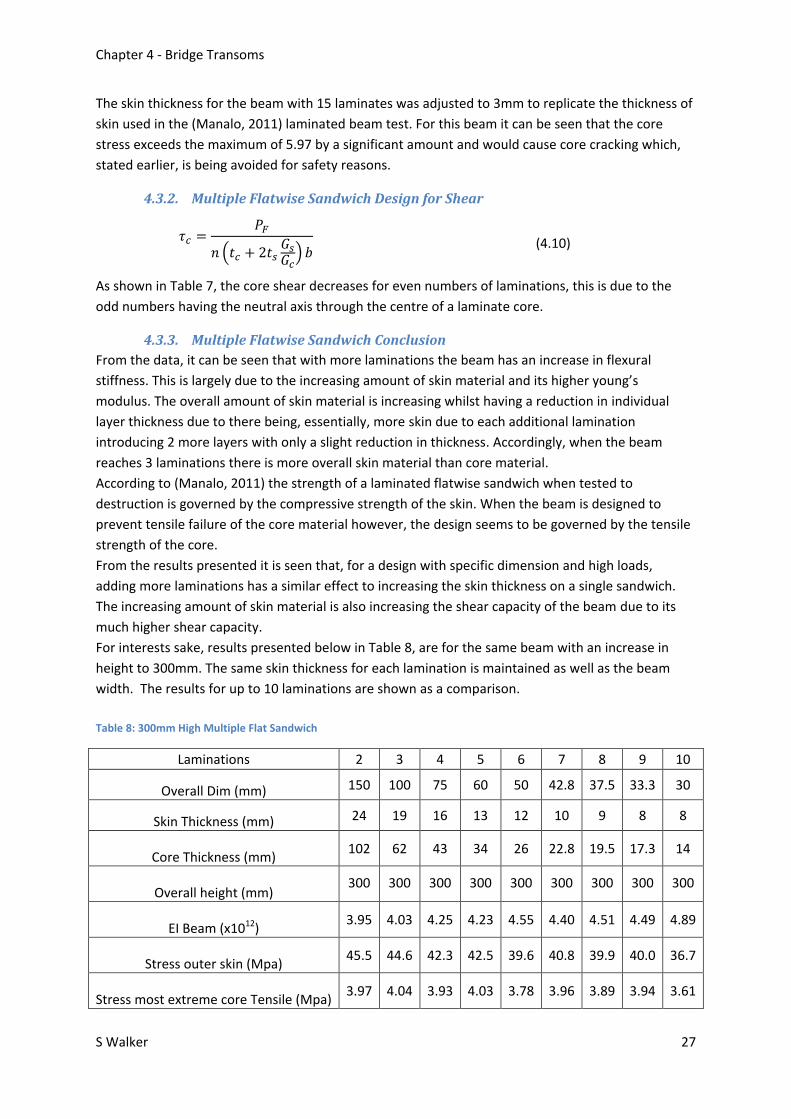
The skin thickness for the beam with 15 laminates was adjusted to 3mm to replicate the thickness of
skin used in the (Manalo, 2011) laminated beam test. For this beam it can be seen that the core
stress exceeds the maximum of 5.97 by a significant amount and would cause core cracking which,
stated earlier, is being avoided for safety reasons.
4.3.2. Multiple Flatwise Sandwich Design for Shear
𝜏𝑐 =𝑃𝐹
𝑛 (𝑡𝑐 + 2𝑡𝑠𝐺𝑠𝐺𝑐
) 𝑏 (4.10)
As shown in Table 7, the core shear decreases for even numbers of laminations, this is due to the
odd numbers having the neutral axis through the centre of a laminate core.
4.3.3. Multiple Flatwise Sandwich Conclusion
From the data, it can be seen that with more laminations the beam has an increase in flexural
stiffness. This is largely due to the increasing amount of skin material and its higher young’s
modulus. The overall amount of skin material is increasing whilst having a reduction in individual
layer thickness due to there being, essentially, more skin due to each additional lamination
introducing 2 more layers with only a slight reduction in thickness. Accordingly, when the beam
reaches 3 laminations there is more overall skin material than core material.
According to (Manalo, 2011) the strength of a laminated flatwise sandwich when tested to
destruction is governed by the compressive strength of the skin. When the beam is designed to
prevent tensile failure of the core material however, the design seems to be governed by the tensile
strength of the core.
From the results presented it is seen that, for a design with specific dimension and high loads,
adding more laminations has a similar effect to increasing the skin thickness on a single sandwich.
The increasing amount of skin material is also increasing the shear capacity of the beam due to its
much higher shear capacity.
For interests sake, results presented below in Table 8, are for the same beam with an increase in
height to 300mm. The same skin thickness for each lamination is maintained as well as the beam
width. The results for up to 10 laminations are shown as a comparison.
Table 8: 300mm High Multiple Flat Sandwich
Laminations 2 3 4 5 6 7 8 9 10
Overall Dim (mm) 150 100 75 60 50 42.8 37.5 33.3 30
Skin Thickness (mm) 24 19 16 13 12 10 9 8 8
Core Thickness (mm) 102 62 43 34 26 22.8 19.5 17.3 14
Overall height (mm) 300 300 300 300 300 300 300 300 300
EI Beam (x1012) 3.95 4.03 4.25 4.23 4.55 4.40 4.51 4.49 4.89
Stress outer skin (Mpa) 45.5 44.6 42.3 42.5 39.6 40.8 39.9 40.0 36.7
Stress most extreme core Tensile (Mpa) 3.97 4.04 3.93 4.03 3.78 3.96 3.89 3.94 3.61

Analysis of the behaviour of fibre composite transom decks for railway bridges 28
From these results it can be determined that with an increase in height of the beam, the core stress
is reduced by around 32%. This is due to the increased flexural stiffness caused by the increased
dimension of the core enabling the skins to be further away from the neutral axis and resisting more
of the tensile and compressive forces. The results prove that in this particular case the core and skin
material are not particularly suited for a beam with these combinations of shear and bending
moment combined with specific dimension of height and breadth.
Another comparison is shown below in Table 9 for a wider beam section of 350 mm but with the
same 209 mm height.
Table 9: 350 mm Wide Multiple Flat Sandwich
Laminations 2 3 4 5 6 7 8 9 10
Overall Dim 104.5 69.67 52.25 41.80 34.83 29.86 26.13 23.22 20.90
Skin Thickness 24 19 16 13 12 10 9 8 8
Core Thickness 56.5 31.66 20.25 15.8 10.83 9.857 8.125 7.222 4.9
Overall height 209 209 209 209 209 209 209 209 209
EI Beam (x1012) 2.05 2.15 2.29 2.30 2.49 2.41 2.48 2.47 2.70
Stress outer skin
(Mpa) 61.11 58.44 54.74 54.60 50.44 51.98 50.65 50.81 46.39
Stress most extreme
core Tensile (Mpa) 4.88 4.96 4.81 4.96 4.63 4.88 4.80 4.87 4.44
It is also clear from these results that the width plays a part in reducing the core tensile stress, as the
core tensile stress in this layout has been reduced from 5.89 in the original layout to 4.88, a
reduction of 17%. This is again due to an increased amount both skin increasing the beam flexural
stiffness. This will be further explored in chapter 5 and the design for a wide panel. Finite element
modelling will be done on flatwise multiple laminate with 4 layers, as this is the maximum amount of
layers with the skin still thinner than the core, which is a major design criteria for classification as a
composite sandwich.

Chapter 4 - Bridge Transoms
S Walker 29
4.4. Multiple Edge Sandwich Design for Bending
The Flexural stiffness of the beam with multiple sandwiches oriented in flatwise uses equation 4.9
and is much simpler to implement for more layers being simply multiples of the EI for 1 layer.
An excel spreadsheet was again utilised for calculation of the maximum stress developed at the
extreme fibres of the skin and core. The results are presented below Table 10. It is clear that in order
to reduce the maximum tensile stress in the core material the skin thickness must be such that there
is actually less core material than skin material. One of the advantages of composite sandwiches is
that they are relatively light for their strength; this is mostly due to the lower density of the core and
larger amount compared to the higher density skin. The configurations needed in the edgewise
layout requires more skin than core, and therefore would be heavy and difficult to manufacture.
Table 10: Multiple Edgewise layout
Laminations 2 3 4 5 6 7 8 9 10 11 12
Overall Dim (mm) 145 96.6 72.5 58.0 48.3 41.4 36.2 32.2 29.0 26.4 24.2
Skin Thickness (mm) 54 36 27 22 18 16 14 12 11 10 9
Core Thickness (mm) 37 24.67 18.5 14 12.3 9.43 8.25 8.22 7 6.36 6.17
Overall Width (mm) 290 290 290 290 290 290 290 290 290 290 290
EI (Nmm2)(x1012) 2.18 2.18 2.18 2.22 2.18 2.25 2.25 2.18 2.22 2.22 2.18
Stress skin Top/Bot (Mpa)
57.4 57.4 57.4 56.5 57.4 55.6 55.6 57.4 56.5 56.5 57.4
Stress core Top/Bot (Mpa)
5.96 5.96 5.96 5.87 5.96 5.78 5.78 5.96 5.87 5.87 5.96
Shear Skin (Mpa) 6.25 6.25 6.25 6.16 6.25 6.07 6.07 6.25 6.16 6.16 6.25
Beam Max Shear
(kN) 1324 1324 1324 1344 1324 1363 1363 1324 1344 1344 1324
Beam Max B.M
(kN.m) 164 164 164 166 164 169 169 164 166 166 164
As described in the previous section, if the height dimension of the beam is increased then the
tensile force in the core will reduce which will then allow a reduction in skin thickness. Due to the
restricted beam height this is not possible. When the beam is designed as a panel, the increased
width may lower the core maximum tensile stress; this will be further investigated in Chapter 5.

Analysis of the behaviour of fibre composite transom decks for railway bridges 30
4.4.1. Multiple Sandwich Edge Layout Design for Shear
The calculation for shear is based on equation 4.11 developed by (Manalo, 2011). The calculations
were performed in an excel spreadsheet with the results also presented in Table 8. Again it is clear
that an edgewise layout provides substantial benefit from a shear perspective.
𝜏𝑠 =𝑃𝐸
𝑛 (𝑡𝑐𝐺𝑐𝐺𝑠
+ 2𝑡𝑠) 𝐷 (4.11)
4.4.2. Multiple Sandwich Edge Layout Conclusion
As with the flat layout, the beam needs more height to allow a combination of skin and core material
that is feasible. The result for the shear in edgewise layout compared to the same amount of
laminations in a flatwise layout shows an increase of 30%. Due to the increased shear in the
edgewise layout a third combination is proposed with laminations glued in an edgewise layout and
skin material added to the top and bottom. This orientation is investigated in the following section.
4.5. Combination Layout
The combination layout of edgewise laminated composite fibre sandwiches with flatwise glass fibre
skins top and bottom is proposed and shown below in Figure 15
Figure 15: Combination Layout
It is hoped that this layout will provide the best of both multiple lamination layouts with the top and
bottom flatwise skins carrying the majority of the bending stress, along with the edgewise
sandwiches carrying the majority of the shear.

Chapter 4 - Bridge Transoms
S Walker 31
4.5.1. Combination design for bending
The equations 4.8 and 4.9 were adjusted and combined in order to calculate the flexural stiffness of
the beam with various combinations of:
Number of edgewise laminations
Thickness of skin for edgewise laminations
Thickness of skin on top and bottom of beam
The calculations were performed in an excel spreadsheet to speed up the adjustment of parameters.
4.5.2. Combination design for shear
As the beam had no core component on the top and bottom of the beam in a flatwise layout, and
due to the fact that maximum shear is developed towards the middle of the beam, equation 4.11
was solely used to calculate the shear carried by the edgewise skins. The calculations performed in
an excel spreadsheet for ease of adjustment.

Analysis of the behaviour of fibre composite transom decks for railway bridges 32
4.5.3. Combination design conclusion
Results for combination arrangement are shown below in Table 11 Table 11: Combination Layout part 1
Laminations 2 3 4 5 6 7 8 9 10
Overall Dim 145 96.6 72.5 58.0 48.3 41.4 36.2 32.2 29.0
Lamination Skin Thickness 6 4 3 3 3 3 3 3 3
Core Thickness 133. 88.7 66.5 52.0 42.3 35.4 30.3 26.2 23.0
Overall Width 290 290 290 290 290 290 290 290 290
Top/Bottom Skin Thickness 24 24 24 24 24 24 24 24 24
Height 161 161 161 161 161 161 161 161 161
EI Edgewise skin & Core (x1012) 0.23 0.23 0.23 0.25 0.27 0.30 0.32 0.35 0.37
EI top bottom Skin (x1012) 1.54 1.54 1.54 1.54 1.54 1.54 1.54 1.54 1.54
EI Total (x1012) 1.77 1.77 1.77 1.79 1.81 1.84 1.86 1.89 1.91
Stress skin Top/bot (Mpa) 71 71 71 70.0 69.1 68.2 67.3 66.5 65.7
Stress core top/bot (Mpa) 5.68 5.68 5.68 5.60 5.53 5.45 5.38 5.32 5.25
Shear Stress Skin (Mpa) 27.6 27.6 27.6 25.6 23.9 22.5 21.2 20.1 19.0
Laminations 11 12 13 14 15
Overall Dim 26.3 24.1 22.3 20.7 19.3
Lamination Skin Thickness 3 3 3 3 3
Core Thickness 20.4 18.2 16.3 14.7 13.3
Overall Width 290 290 290 290 290
Top/Bottom Skin Thickness 24 24 24 24 24
Height 161 161 161 161 161
EI Edgewise skin & Core (x1012) 0.39 0.42 0.44 0.47 0.49
EI top bottom Skin (x1012) 1.54 1.54 1.54 1.54 1.54
EI Total (x1012) 1.93 1.96 1.98 2.01 2.03
Stress skin Top/bot (Mpa) 64.9 64.0 63.3 62.5 61.8
Stress core top/bot (Mpa) 5.18 5.12 5.06 5.00 4.94
Shear Stress Skin (Mpa) 18.0 17.2 16.4 15.8 15.1
The results show that a much lower skin thickness of as little as 3mm for the edgewise laminations
can be used whilst still maintaining sufficient shear strength. The use of the 24mm top and bottom
skin now carries enough of the tensile stress so that the core material is below its maximum of 5.97
MPa.
This orientation of skin and core material provides another possibility for usage as transom decking
and will be further investigated in chapter 5. Finite Element model for the beams with 4 laminations

Chapter 4 - Bridge Transoms
S Walker 33
is presented in Chapter 6. 4 laminates was chosen as it was the most laminates possible whilst still
maintaining more core material than skin.
4.6. Conclusions
With the given loading for a train and the limited dimensions required of 290 w x 209 h, the
laminated composite sandwiches requires significant amounts of skin material. It is not
recommended to replace individual transom beams with laminated composite sandwiches in either
the flatwise or edgewise orientation. For the combination arrangement however there is potential
for replacement which should be further investigated, but which is beyond the scope of this project.

Analysis of the behaviour of fibre composite transom decks for railway bridges 34
Chapter 5 - Transom Panel
5. Rail Loads for Bridge Deck Panel The proposed dimensions (mm) of 2500(L) x 1200(W) x 209(H) is proposed for the panel. This allows
rail attachments at 600mm centres whilst still allowing 300mm at either end of the panel as shown
below in Figure 16. These dimensions also represent those the manufacturer makes the panels in.
Figure 16: Proposed Panel Layout
The dimensions of the rail were sourced from the (Onesteel, 2011) rail track material catalogue for
68 Kg rail. The width of the bottom flange is 152.4 mm. For ease of modelling, the width has been
set to 100mm.
From Chapter 3 it was shown that according to AS5100 the rail load is distributed over 1.2 metres of
rail. Accordingly the 1.2 metre wide panel carries the full load of ½ of an axle load of 360kN. The rail
load is therefore 180 kN / 1.2 m which equals 150 kN/m.
The new factored load is now (1+α)*Load Factor * Load
Where α is still 1.6, and the load factor is also 1.6.
This now makes the load 2.6*1.6*150 = 624 kN/m
The bending moment for the panel is now 624*1.2*0.25 = 187.2 kN.m
The shear is (2/3*1.6)*1.6*180 = 595.2 Kn

Chapter 5 - Transom Panel
S Walker 35
5.1. Analysis in bending/Shear
Theoretical exploration of the stress in the core and skin for flatwise, edgewise and combination
orientation is performed to determine the best candidate for potential use as rail bridge transom
decking in bending.
5.1.1. Multiple Flat Sandwiches
The results for the panel with up to 11 laminations are shown below in Table 12. The maximum
number of laminations was set at 11 due to the overall dimension of the individual sandwich layers
being around 20mm which is desirable as it is the most easily produced in the factory. Adjustment of
the excel spreadsheet developed earlier is used to produce the results as it allowed for easy
adjustment of panel width, depth, skin thickness and number of laminations.
Table 12: Multiple Flatwise Layout Panel
Laminations 2 3 4 5 6 7 8 9 10 11
Overall Dim 104.5 69.67 52.25 41.80 34.83 29.86 26.13 23.22 20.90 19.00
Skin Thickness 10 9 7 6 5 5 4 4 3 3
Core Thickness 84.5 51.7 38.3 29.8 24.8 19.9 18.1 15.2 14.9 13.0
Overall height 209 209 209 209 209 209 209 209 209 209
EI Panel (x1012) 3.96 4.31 4.25 4.37 4.33 4.78 4.49 4.86 4.26 4.55
Stress outer skin (Mpa) 63.40 58.14 59.04 57.35 57.95 52.44 55.91 51.55 58.84 55.09
Stress most extreme core Tensile (Mpa)
5.95 5.51 5.72 5.61 5.72 5.18 5.58 5.14 5.93 5.55
Shear (Core) (Mpa) 1.19 1.02 0.99 0.95 0.95 0.87 0.92 0.85 0.95 0.90
Max Shear Beam 2247 2638 2694 2806 2806 3085 2918 3141 2806 2974

Analysis of the behaviour of fibre composite transom decks for railway bridges 36
5.1.2. Multiple Edge Sandwiches
Results for the panel with up to 12 laminations are shown below in Table 13.
Table 13: Edgewise Multiple Sandwich Layout panel
Laminations 2 3 4 5 6 7 8 9 10 11 12
Overall Dim 600 400 300 240 200 171 150 133 120 109 100
Skin Thickness 90 70 50 40 30 26 23 20 18 17 15
Core Thickness 420 260 200 160 140 119 104 93.3 84.0 75.1 70
Overall Width 1200 1200 1200 1200 1200 1200 1200 1200 1200 1200 1200
EI (x1012) 4.36 4.88 4.71 4.71 4.36 4.39 4.43 4.36 4.36 4.48 4.36
Stress skin Top/Bot (Mpa)
57.5 51.3 53.2 53.2 57.5 57.0 56.6 57.5 57.5 55.9 57.5
Stress core top/bot (Mpa)
5.97 5.33 5.52 5.52 5.97 5.92 5.87 5.97 5.97 5.80 5.97
Shear Skin (Mpa)
5.74 5.21 5.38 5.38 5.74 5.70 5.67 5.74 5.74 5.61 5.74
Beam Max
Shear (kN) 2881 3173 3076 3076 2881 2901 2920 2881 2881 2949 2881
5.1.3. Multiple Combination Panel
The results for the panel with 10 to 20 edge laminations are shown below in Table 14. The required
amount of laminations for a panel which comprised 20mm individual laminations is 60, which was
determined to be unfeasible to manufacture.
Table 14: Combination Layout Panel
Laminations 10 11 12 13 14 15 16 17 18 19 20
Lamination Skin Thickness
3 3 3 3 3 3 3 3 3 3 3
Core Thickness 114 103.1 94.0 86.3 79.7 74.0 69.0 64.6 60.7 57.2 54.0
Overall Width 120 109 100 92 86 80 75 71 67 63 60
Top/Bottom Skin Thickness
10 10 10 10 10 10 10 10 10 10 10
EI Total (x1012) 4.33 4.37 4.41 4.45 4.49 4.53 4.57 4.61 4.64 4.68 4.72
Stress skin top/bot (Mpa)
57.8 57.35 56.8 56.3 55.8 55.3 54.9 54.4 53.9 53.5 53.1
Stress core top/bot (Mpa)
5.43 5.38 5.33 5.29 5.24 5.20 5.15 5.11 5.07 5.02 4.98
Shear Stress Skin (Mpa)
12.8 12.62 12.3 12.1 11.9 11.6 11.4 11.2 11.0 10.8 10.6

Chapter 5 - Transom Panel
S Walker 37
5.2. Analysis in Shear
Theoretical analysis of the shear in the core for flatwise and shear in the skin for edgewise and
combination orientations is performed to predict the best suitable candidate for potential use as rail
bridge transom decking in shear. The results are shown in Table 12 for the core in flatwise, Table 13
for the skin in edgewise and Table 14 for the skin in edgewise for combination layout.
5.3. Conclusions
It is interesting from the results of Table 12 and Table 13 that the flexural stiffness is similar when
the panels reach around 10 laminations. The skin thickness for the sandwich in the flatwise layout
being 20.9 mm has the advantage of being easier to create due to the production process being set
up for individual panels of around 20mm thickness. Also when the beam reaches around 10
laminations the beam maximum shear is similar at around 2800 Kn.
The combination layout shows promise with a similar flexural stiffness of 4.3x10¹² Nmm2and with
only an edgewise skin thickness of 3mm. The overall individual panel width of around 70mm or more
will cause production difficulty as the width is much more than the usual 20mm. The 10 mm thick
top and bottom skin will increase the complexity of the design with another 2 layers of skin required
to be bonded to the edges of the laminations that have already been bonded together. Due to the
simplicity of existing manufacture, the obvious choice to progress with is the panel with 10 layers of
20mm sandwiches in a flatwise layout.

Analysis of the behaviour of fibre composite transom decks for railway bridges 38
Chapter 6 - Finite Element Analysis
6. Finite Element Analysis Beams and panels re modelled using the Strand7 Finite element analysis program. Skins and the core
are made from Hexa16 bricks and the beam is subdivided once the model has been created. Table
15 summarizes the number of bricks, nodes and the computation time. The naming convention is
organised with the letter B for Beam, P for Panel, S and M representing a single or multiple layer
sandwich respectively, a digit representing the number of layers, with the flatwise or edgewise
designated F or E respectively. The computer used to model the beam is a high performance 64 bit
ASUS gaming laptop with Corei7 processor at 2.4 Ghz and 16 GB memory. This level of computing
power enables the specimens to be analysed as a whole. The rail track is added to the beam at the
250 mm offset centre line, represented by a 100mm wide plate and 30mm thick. The point load was
transformed into a normal pressure in order to distribute the load evenly over the plate. The
corresponding pressure is 374.4x10³ / (100*290) = 12.91 Mpa for the 290 x 209 mm beam. The panel
load was previously determined as 624 Kn/m with the panel being 1.2 metres wide this equals 748.8
kN. The pressure is therefore (748800/100*1200) = 6.24 Mpa
Table 15: F.E. model for Sandwich Beam
Specimen Number Bricks Number Nodes CPU Time
BS1F 181440 193851 2 Hrs 42 Mins 32 Sec
BM4F 233856 250154 2 Hrs 15 Mins
BM4E 60480 71475 6 Mins 47 Sec
BM4C 133056 174913 5 min 24 Sec
PM10F 201600 215475 2 Hrs 18 Mins 43 sec
PM10E 168000 208974 13 Mins
PM10C 238560 273445 2 Hrs 21 Mins 54
sec
6.1. Finite Element Models
The models are presented below before solving to give an idea of the layout of the sandwich. The
core is red and the skins are blue. The force is represented by the brown arrows and the edges of the
beam are supported by nodes with x,y,z limited movement and only rotation about the Y axis
allowed. The model was run with linear static solver.

Chapter 6 - Finite Element Analysis
S Walker 39
Figure 17: F.E. Model for specimen BS1F
Figure 18: F.E. Model for Specimen BM4F
Figure 19: F.E. Model for Specimen BM4E
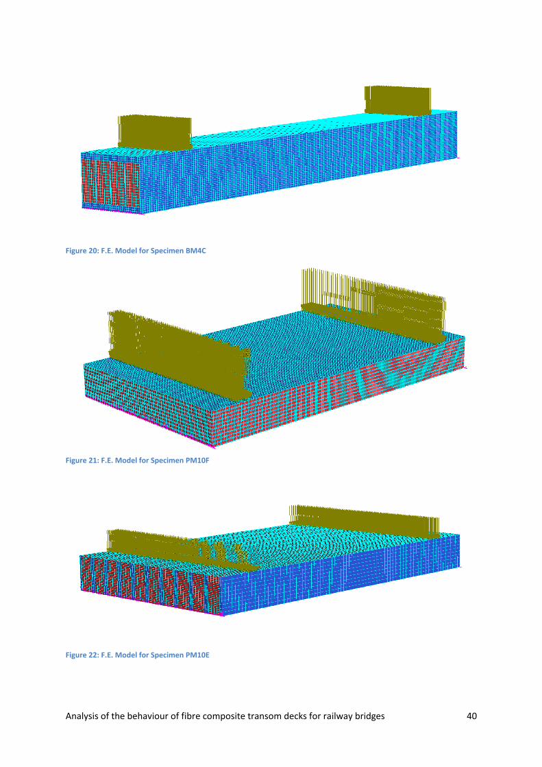
Analysis of the behaviour of fibre composite transom decks for railway bridges 40
Figure 20: F.E. Model for Specimen BM4C
Figure 21: F.E. Model for Specimen PM10F
Figure 22: F.E. Model for Specimen PM10E

Chapter 6 - Finite Element Analysis
S Walker 41
Figure 23: F.E. Model for specimen PM10C
6.2. Modelling Results
6.2.1. Transom Beams 290 w x 209 h
The following section presents results of finite element modelling for beams that were aimed to
mimic the dimensions of existing transoms.
Figure 24: F.E. Model BS1F Shear
Figure 25: F.E. Model BS1F Stress
The maximum stress is concentrated around the node restraints and rails which is not accounted for
with the numerical analysis. The shear in the skins in areas other than the loading and restraint
points is less than their maximum of 27.8 Mpa. The maximum core tensile stress according to the
model is 8.8 Mpa, again, at the location of the nodal restraint. The values otherwise are less than the
core maximum tensile stress of 5.97 Mpa. The beam would seem appropriate for the task.

Analysis of the behaviour of fibre composite transom decks for railway bridges 42
Figure 26: F.E. Model BM4F Shear
Figure 27: F.E.M. BM4F Axial Stress
Again for specimen BM4F the maximum axial stresses are around the nodal restraints and rail edges.
The beam otherwise develops less stress and shear than the maximums for the skin and core.
Figure 28: F.E. Model BM4E Shear

Chapter 6 - Finite Element Analysis
S Walker 43
Figure 29: F.E. Model BM4E Axial Stress
The results for BM4E show that the beam is generally sufficient, with the skins having less than 27.8
Mpa shear in the skin. The axial force is again generally sufficient except for around the rail and
nodal restraints.
Figure 30: F.E. Model BM4C Shear
Figure 31: F.E. Model BM4C Axial Stress
The combination beam shows the most promise with the limited dimensions available when
arranged as a bridge transom beam. It shows reduced stress around the loading points, possibly due
to thicker skin material at these points; there are some rather high shear within the beam edge skins

Analysis of the behaviour of fibre composite transom decks for railway bridges 44
that may cause localised failure. This may be remedied by increasing the thickness of the skin on the
edges of the beam.
6.2.2. Panels 1200 w x 209 h
The following section presents the finite element model results for the panel arrangements.
Figure 32: F.E. Model PM10F Shear
Figure 33: F.E. Model PM10F Axial Stress
It is clear that when the laminations are created wider into a panel of 1200 mm width the stress is
dramatically reduced. The stress for the flatwise panel layout is predominantly compressive. The
concentrations around the nodal restraints and rail may be reduced further through the use of
thicker skin at the top under the rails as shown in specimen BM4C and applied also to the bottom of
the panel. Deflections at mid span are listed at 11.3 mm.

Chapter 6 - Finite Element Analysis
S Walker 45
Figure 34: F.E. Model PM10E Shear
Figure 35: F.E. Model PM10E Axial Stress
The edgewise layout shows that the stresses are a mix of compressive and tensile. The deflection at
mid span is now listed as 6.5 mm which indicates the beam has a higher flexural stiffness as
expected from the numerical calculations, predominantly due to the thickness of the skin in the
edgewise direction providing increased stiffness.
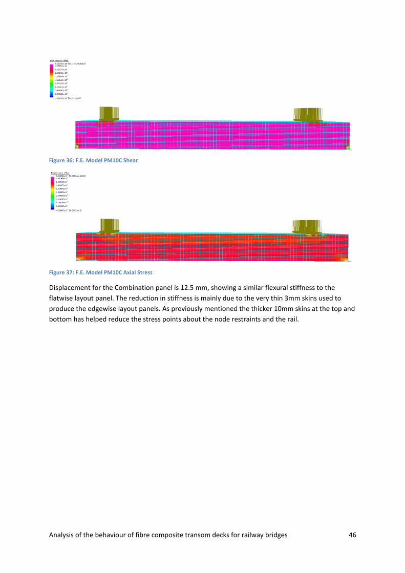
Analysis of the behaviour of fibre composite transom decks for railway bridges 46
Figure 36: F.E. Model PM10C Shear
Figure 37: F.E. Model PM10C Axial Stress
Displacement for the Combination panel is 12.5 mm, showing a similar flexural stiffness to the
flatwise layout panel. The reduction in stiffness is mainly due to the very thin 3mm skins used to
produce the edgewise layout panels. As previously mentioned the thicker 10mm skins at the top and
bottom has helped reduce the stress points about the node restraints and the rail.

Chapter 7 - Conclusions
S Walker 47
Chapter 7 - Conclusions
7. Conclusions
7.1. Summary
A new type of rail bridge transom involving the use of decking panels has been introduced to
improve safety of railway bridges. Current available materials do not meet the criteria for use as
decking panels without having trade-offs in terms of durability, life span or characteristic material
properties. The development of fibre composite technologies that can mimic the desirable
properties of wood without the accompanied drawbacks of durability and limited life has enabled
them to become a viable alternative.
The literature investigation conducted suggests that the fibre composite sandwich can be produced
that mimics the properties of hardwood, and are almost maintenance free along with being fire
resistant. This project is the first to examine a laminated composite sandwich panel constructed
from the unique fibre composite sandwich panel for use as rail bridge decking.
7.2. Major Conclusions
A study has been undertaken on various combinations of skin and core thicknesses of a unique fibre
composite sandwich in a variety of layouts. The following represents the major findings of this study:
Laminating the composite sandwiches together into a layered panel, results in a more stable
section than for an individual sandwich in terms of flexural stiffness.
The greater the skin thickness for layer laminations, the greater was the flexural stiffness of
the panel.
In the flatwise layout the increasing ratio of skin to core with increasing laminations resulted
in an increase in shear capacity.
The flexural stiffness of beams created in an edgewise layout is increased to that of a
flatwise layout for equal skin amounts, which is an advantage due to the lower deflections
for stiffer beams giving better serviceability.
The shear capacity of panels with an edgewise layout is increased to those of flatwise layout,
however, there is significant complexities of the panel construction in both the edgewise
and combination layout; any reduction in shear stress should be considered against this
increased production complexity.
With limited dimensions of width or height or both, the edgewise layout requires the same
total thickness of skin and core no matter how many laminations are used.
Creating another layer of skin onto the edgewise layout panel provides additional bending
capacity but increases the complexity of construction.
7.3. Application to railway transom decking
From the theoretical and finite element analysis of laminated composite sandwich panels it appears
that all the designs listed will cope with the static loads expected for a railway bridge, the
implementation comes down to the designs practicality for production. The most obvious candidate
for production is the laminated flatwise panel with 10 laminations of around 20mm height which is

Analysis of the behaviour of fibre composite transom decks for railway bridges 48
ideal considering the manufacturers ability to mass produce individual sandwich panels in these
dimensions.
7.4. Future recommended research
It is recommended that full scale laboratory load testing should be performed on multiple layer
sandwiches of 1200 mm wide 2400 metre long, 20 mm thick sandwich panels stacked 10 high to
form an overall thickness (including glue lines) of 209 mm in order to confirm the strength of the
panel.
Stress cycling needs to be performed on the panel in order to determine the reaction over time to
the expected repeated loads to provide an estimate of durability.
The ability of the panel to effectively hold rail fastenings without movement or error should be
investigated.
Where dimensions for height and width are limited, the combination orientation of edgewise
laminations with an additional top and bottom skin showed promise. There is an opportunity for
further analysis of the combination arrangement for application as structural members due to the
increase in flexural stiffness and shear capacity.
Finally, a thorough cost/benefit analysis should be undertaken which takes into consideration the
total lifetime cost of the fibre composite panel compared with existing transoms. The cost for fibre
composite panels should decrease as production becomes more automated which should also be
taken into consideration.

References
S Walker 49
References Adams, J 1991, Cost Effective Strategy for Track Stability and Extended Asset Life through Planned Timber Sleeper Retention, Institution of Engineers, Australia, Barton, ACT. Akbiyik, A, Lamanna, AJ & Hale, WM 2007, 'Feasibility investigation of the shear repair of timber stringers with horizontal splits', Construction and Building Materials, vol. 21, no. 5, pp. 991-1000, <http://www.sciencedirect.com/science/article/pii/S0950061806000390>. B4B, 2011, Boral for Builders, Boral National Publication, online,
http://www.boral.com.au/brochures/ordering/PDF/BBP_05402B4B_News_LR%20(3).pdf?pdfName=
BBP_05402B4B_News_LR%20(3).pdf
Bekuit, J.R.B., Oguamanam, D.C.D. and Damisa, O. (2007). A quasi-2D finite element formulation for
the analysis of sandwich beams. Finite Elements in Analysis and Design, 43, 1099-1107.
Bolin, CA, Christopher, AB & Stephen, TS 2013, 'Life Cycle Assessment of Creosote-Treated Wooden Railroad Crossties in the US with Comparisons to Concrete and Plastic Composite Railroad Crossties', Journal of transportation technologies, vol. 3, no. 2, pp. 149-61. Duan, L, Chen, W. F. 1999, Bridge engineering handbook, CRC Press, Boca Raton FL. Esveld, C 2001, Modern railway track, 2nd ed. edn, MRT Productions, The Netherlands. Ferdous, W & Manalo, A 2014, 'Failures of mainline railway sleepers and suggested remedies – Review of current practice', Engineering Failure Analysis, vol. 44, pp. 17-35, <http://www.sciencedirect.com/science/article/pii/S1350630714001344>. Garlock, M, Paya-Zaforteza, I, Kodur, V & Gu, L 2012, 'Fire hazard in bridges: Review, assessment and repair strategies', Engineering Structures, vol. 35, pp. 89-98, <http://www.sciencedirect.com/science/article/pii/S0141029611004408>. Griffin, DWP, Mirza, O, Kwok, K & Kaewunruen, S 2014, 'Composite slabs for railway construction and maintenance: a mechanistic review', The IES Journal Part A: Civil & Structural Engineering, vol. 7, no. 4, pp. 243-62, viewed 2015/08/13, <http://www.tandfonline.com/doi/abs/10.1080/19373260.2014.947909>. Hay, WW 1982, Railroad engineering, 2nd ed. edn, Wiley, New York. Ikarashi, Y, Kaniwa, M-a & Tsuchiya, T 2005, 'Monitoring of polycyclic aromatic hydrocarbons and water-extractable phenols in creosotes and creosote-treated woods made and procurable in Japan', Chemosphere, vol. 60, no. 9, pp. 1279-87, <http://www.sciencedirect.com/science/article/pii/S0045653505001955>. Ivanoff, V 1995, Engineering Mechanics: An Introduction to Statics, Dynamics and Strength of Materials, McGraw-Hill. Loccomposites, Product Brochure, [ONLINE] Available at:
http://www.icsservices.com.au/wkg/pdfs/Carbonlocmanualgeneral5.pdf. <Viewed 10th
February
2015.

Analysis of the behaviour of fibre composite transom decks for railway bridges 50
Manalo, Allan (2011) Behaviour of fibre composite sandwich structures: a case study on railway
sleeper application. [Thesis (PhD/Research)] (Unpublished)
Manalo, AC, Aravinthan, T & Karunasena, W 2010, 'Flexural behaviour of glue-laminated fibre composite sandwich beams', Composite Structures, vol. 92, no. 11, pp. 2703-11, <http://www.sciencedirect.com/science/article/pii/S0263822310000966>. MCKAY, GVEM 2013, 'Recent Australian Developments in Fibre Composite Railway Sleepers', Electronic Journal of Structural Engineering, vol. 13, no. 1, pp. 62-6. Monrroy, M, Ortega, I, Ramírez, M, Baeza, J & Freer, J 2011, 'Structural change in wood by brown rot fungi and effect on enzymatic hydrolysis', Enzyme and Microbial Technology, vol. 49, no. 5, pp. 472-7, <http://www.sciencedirect.com/science/article/pii/S0141022911001864>. P. A. Mendis, 2013, A Review of Behaviour of Prestressed Concrete Sleepers, Special Issue: Electronic Journal of Structural Engineering 13(1). Poisson, F & Margiocchi, F 2006, 'The use of dynamic dampers on the rail to reduce the noise of steel railway bridges', Journal of Sound and Vibration, vol. 293, no. 3–5, pp. 944-52, <http://www.sciencedirect.com/science/article/pii/S0022460X05008047>. Profillidis, VA 1995, Railway engineering, Avebury Technical, Aldershot. Railcorp, 2015, New underbridges, track structure requirements, drainage and waterproofing and
derailment containment devices, Technical Note, Transport for NSQ, Online,
http://www.asa.transport.nsw.gov.au/sites/default/files/asa/railcorp-legacy/disciplines/civil/esc-
310.pdf
StandardsAustralia 2004, 'Australian Standard®Bridge design'. Ticoalu, A, Aravinthan, T & Karunasena, W 2008, 'An investigation on the stiffness of timber sleepers for the design of fibre composite sleepers', in 20th Australasian Conference on the Mechanics of Structures and Materials (ACMSM 20): Futures in Mechanics of Structures and Materials: proceedings of the 20th Australasian Conference on the Mechanics of Structures and Materials (ACMSM 20): Futures in Mechanics of Structures and Materials, T Aravinthan, et al. (eds.), Taylor & Francis (CRC Press), Toowoomba, Australia, pp. 865-70. Van den Bulcke, J, De Windt, I, Defoirdt, N, De Smet, J & Van Acker, J 2011, 'Moisture dynamics and fungal susceptibility of plywood', International Biodeterioration & Biodegradation, vol. 65, no. 5, pp. 708-16, <http://www.sciencedirect.com/science/article/pii/S0964830511000710 http://www.ncbi.nlm.nih.gov/pmc/articles/PMC3993986/pdf/nihms562096.pdf>. Vinden, P, Torgovnikov, G & Hann, J 2011, 'Microwave modification of Radiata pine railway sleepers for preservative treatment', European Journal of Wood and Wood Products, vol. 69, no. 2, pp. 271-9, <http://dx.doi.org/10.1007/s00107-010-0428-8 http://link.springer.com/article/10.1007%2Fs00107-010-0428-8>. Webb, DA 2005, 'Tie Guide', Handbook for Commercial Timbers used by the crosstie industry.

References
S Walker 51
W.Y. Yun, L. Ferreira Prediction of the demand of the railway sleepers: a simulation model for the replacement strategies Int J Prod Econ, 81–82 (2003), pp. 589–595 T. Ngo J. Taherinezhad , M. Sofi & Xu, G & Goodell, B 2001, 'Mechanisms of wood degradation by brown-rot fungi: chelator-mediated cellulose degradation and binding of iron by cellulose', Journal of Biotechnology, vol. 87, no. 1, pp. 43-57, <http://www.sciencedirect.com/science/article/pii/S0168165600004302>. Yong, Yun Huang, The old Rail Bridge, Photograph, viewed 17th August 2015,
< https://commons.wikimedia.org/wiki/File:The_old_rail_bridge.jpg>

Analysis of the behaviour of fibre composite transom decks for railway bridges 52
Appendices
A. Flexural Stiffness flatwise and edgewise For the sandwich having equal distance from the centroid of the beam to the centroid of both skin
layers makes di=d/2
The equation for flexural stiffness is:
(EI) A1
Where E = Young’s Modulus of Elasticity, given in table 4.
I = Second moment of area
The equation for second moment of area about a given axis is :
𝐼 =𝑏𝑑3
12+ 𝐴𝑑𝑖
2 A2
Where the moment of inertia for a rectangle is: 𝑏𝑑3
12 A3
The transfer term for parallel axis area:
𝐴𝑑𝑖2 A4
A= is the area
Di = distance between axis
Combining equation A1 with equation A2 for the sandwich consisting of 1 core and 2 skins gives:
𝐸𝐼 = 𝐸𝑐𝐼𝑐 + 2(𝐸𝑠𝐼𝑠)
𝐹𝑜𝑟 𝑡ℎ𝑒 𝑠𝑘𝑖𝑛𝑠 𝐼𝑠 = 𝑏𝑡3
12+ 𝐴𝑑𝑖
2
𝑏𝑢𝑡 𝑑𝑖 =𝑑
2
∴ 𝐼𝑠 = 𝑏𝑡3
12+ 𝑏𝑡 (
𝑑
2)
2
𝑚𝑎𝑘𝑖𝑛𝑔 𝐸𝐼 = 𝐸𝑐
𝑏𝑐3
12+ 2 [𝐸𝑠
𝑏𝑡3
12+ 𝑏𝑡 (
𝑑
2)
2
]
∴ 𝐸𝐼 = 𝐸𝑐
𝑏𝑐3
12+ 𝐸𝑠 [
𝑏𝑡3
6+ (𝑏𝑡
𝑑
2)
2
]


![STEPHEN R. BASSER (121590) BARRACK, RODOS & BACINE · composite decks, pool decks and walkways,” and able to “conceal cracks and splinters up to 1/4 inch,” to “create[] a](https://img.dokumen.tips/doc/110x75/602b82bbaa682713be35efe1/stephen-r-basser-121590-barrack-rodos-bacine-composite-decks-pool-decks.jpg)