Embed Size (px)
Citation preview

8/8/2019 Analysis of Steam Power Plants OB 2010
http://slidepdf.com/reader/full/analysis-of-steam-power-plants-ob-2010 1/57
ANALYSIS OF STEAM POWER PLANTS
8/8/2019 Analysis of Steam Power Plants OB 2010
http://slidepdf.com/reader/full/analysis-of-steam-power-plants-ob-2010 2/57
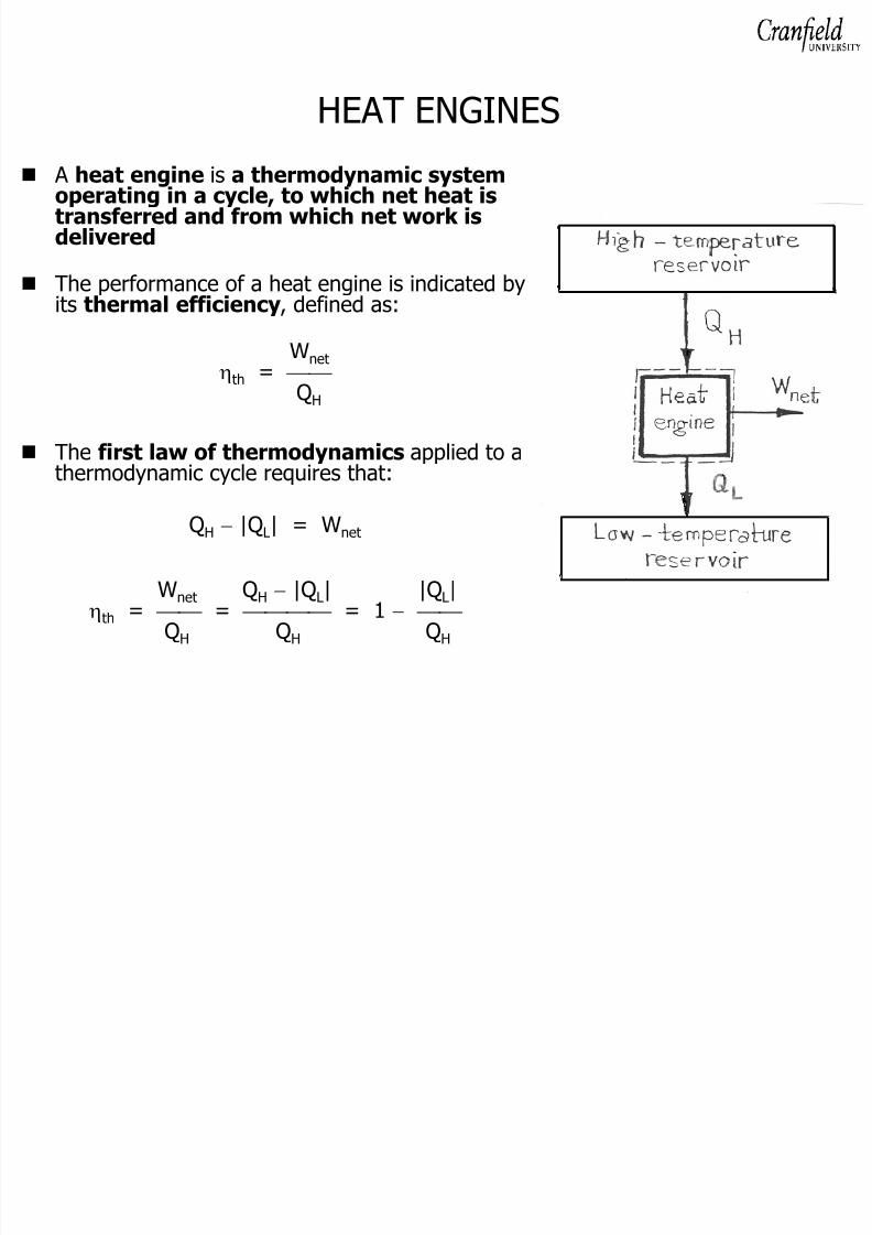
HEAT ENGINES A heat engine is a thermodynamic systemoperating in a cycle, to which net heat istransferred and from which net work isdelivered
The performance of a heat engine is indicated byits thermal efficiency , defined as:
Wnetηth = QH
The first law of thermodynamics applied to athermodynamic cycle requires that:
QH − |Q L| = W net
Wnet QH − |Q L| |Q L|ηth = = = 1 − QH QH QH
8/8/2019 Analysis of Steam Power Plants OB 2010
http://slidepdf.com/reader/full/analysis-of-steam-power-plants-ob-2010 3/57
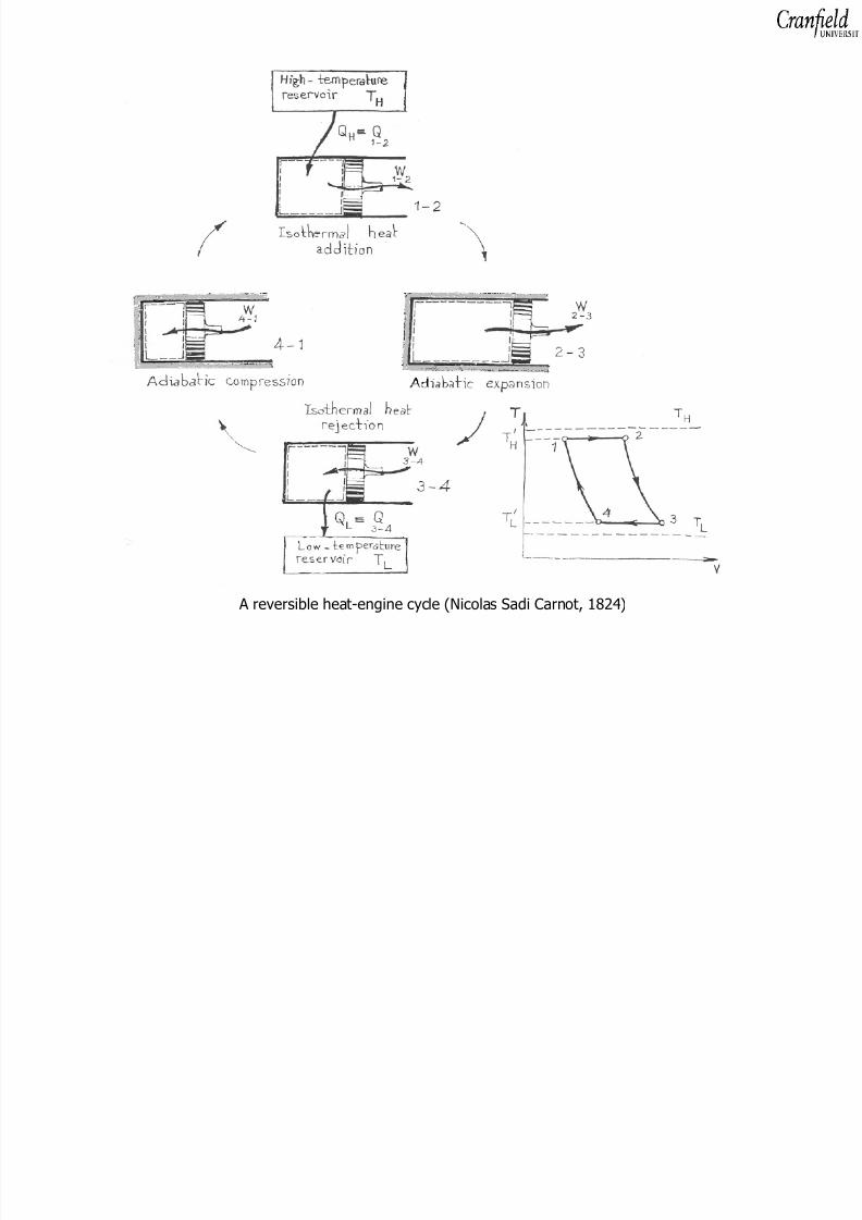
A reversible heat-engine cycle (Nicolas Sadi Carnot, 1824)
8/8/2019 Analysis of Steam Power Plants OB 2010
http://slidepdf.com/reader/full/analysis-of-steam-power-plants-ob-2010 4/57
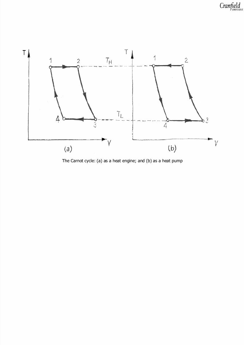
The Carnot cycle: (a) as a heat engine; and (b) as a heat pump
8/8/2019 Analysis of Steam Power Plants OB 2010
http://slidepdf.com/reader/full/analysis-of-steam-power-plants-ob-2010 5/57
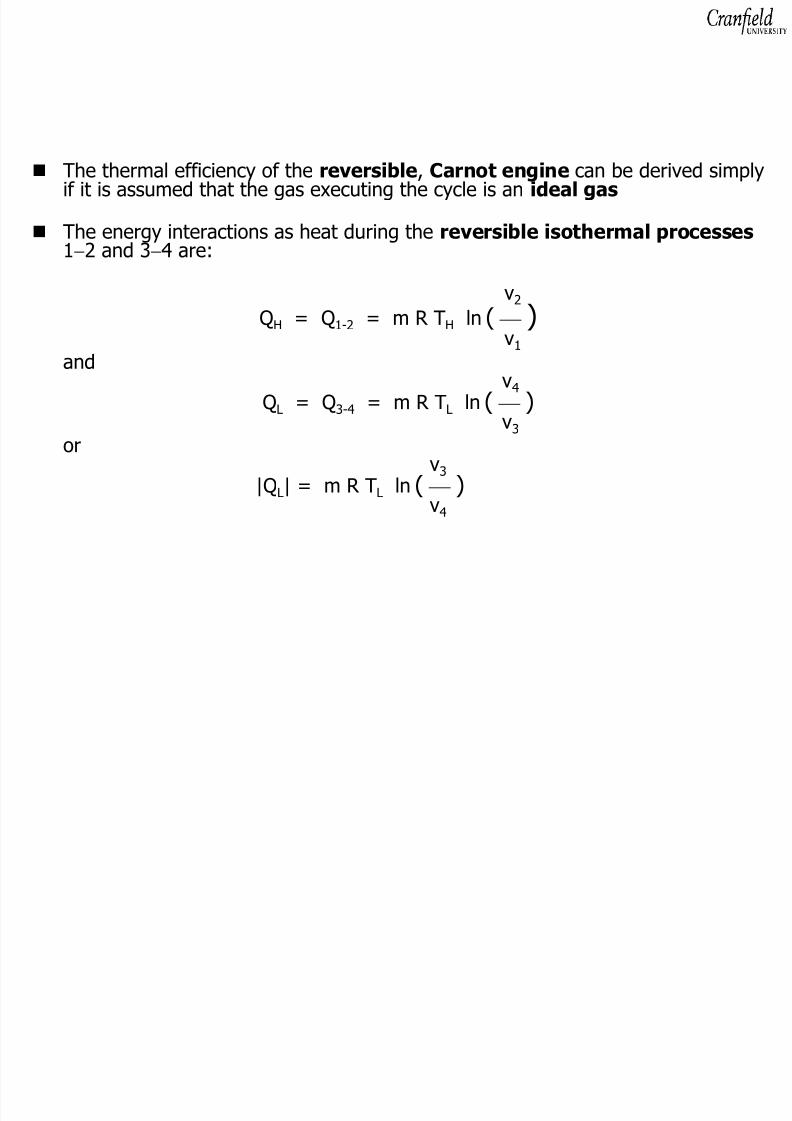
The thermal efficiency of the reversible , Carnot engine can be derived simplyif it is assumed that the gas executing the cycle is an ideal gas
The energy interactions as heat during the reversible isothermal processes1−2 and 3 −4 are:
v2
QH = Q 1-2 = m R T H ln ( )v1and
v4Q
L= Q
3-4= m R T
Lln ( )
v3or
v3|Q L| = m R T L ln ( )
v4

8/8/2019 Analysis of Steam Power Plants OB 2010
http://slidepdf.com/reader/full/analysis-of-steam-power-plants-ob-2010 6/57
For the isentropic processes 2 −3 and 4 −1:
T2 TH v3 (γ −1) = = ( )T3 TL v2
andT1 TH v4 (γ −1)
= = ( )T4 TL v1
v3 v4 v2 v3 = or = v2 v1 v1 v4
8/8/2019 Analysis of Steam Power Plants OB 2010
http://slidepdf.com/reader/full/analysis-of-steam-power-plants-ob-2010 7/57
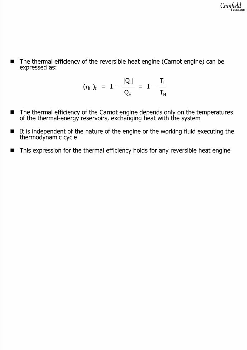
The thermal efficiency of the reversible heat engine (Carnot engine) can beexpressed as:
|Q L| T L(ηth)C = 1 − = 1 −
QH TH
The thermal efficiency of the Carnot engine depends only on the temperaturesof the thermal-energy reservoirs, exchanging heat with the system
It is independent of the nature of the engine or the working fluid executing thethermodynamic cycle
This expression for the thermal efficiency holds for any reversible heat engine

8/8/2019 Analysis of Steam Power Plants OB 2010
http://slidepdf.com/reader/full/analysis-of-steam-power-plants-ob-2010 8/57
The Carnot principle includes two main propositions or corollaries, which areof great use in comparing the performances of cyclic energy converters:
No heat engine, operating between two thermal-energy reservoirs,can be more efficient than a reversible engine operating between
the same two reservoirs All reversible heat engines, operating between two thermal-energyreservoirs, have the same thermal efficiency
The expression for the thermal efficiency of the Carnot engine indicates themaximum possible energy-conversion efficiency of a heat engine operatingbetween the two temperature levels T H and T L

8/8/2019 Analysis of Steam Power Plants OB 2010
http://slidepdf.com/reader/full/analysis-of-steam-power-plants-ob-2010 9/57
STEAM POWER-GENERATION SYSTEMS
Vapour power-systems, using steam as the working fluid developed as a result of the 19th century work of William Rankine , with reciprocating steamengines , at Glasgow University
Steam Rankine-cycle systems remain the principle, most-efficient devices forthermal electric-power generating plants, powered by fossil- and nuclear fuels aswell as renewable energy sources (solar, geothermal and biomass energy)
The Rankine cycle used in power plants is much more complex than the original,simple and ideal Rankine cycle
For practical reasons, modern, steam power-systems employ rotating rather thanreciprocating machinery
8/8/2019 Analysis of Steam Power Plants OB 2010
http://slidepdf.com/reader/full/analysis-of-steam-power-plants-ob-2010 10/57
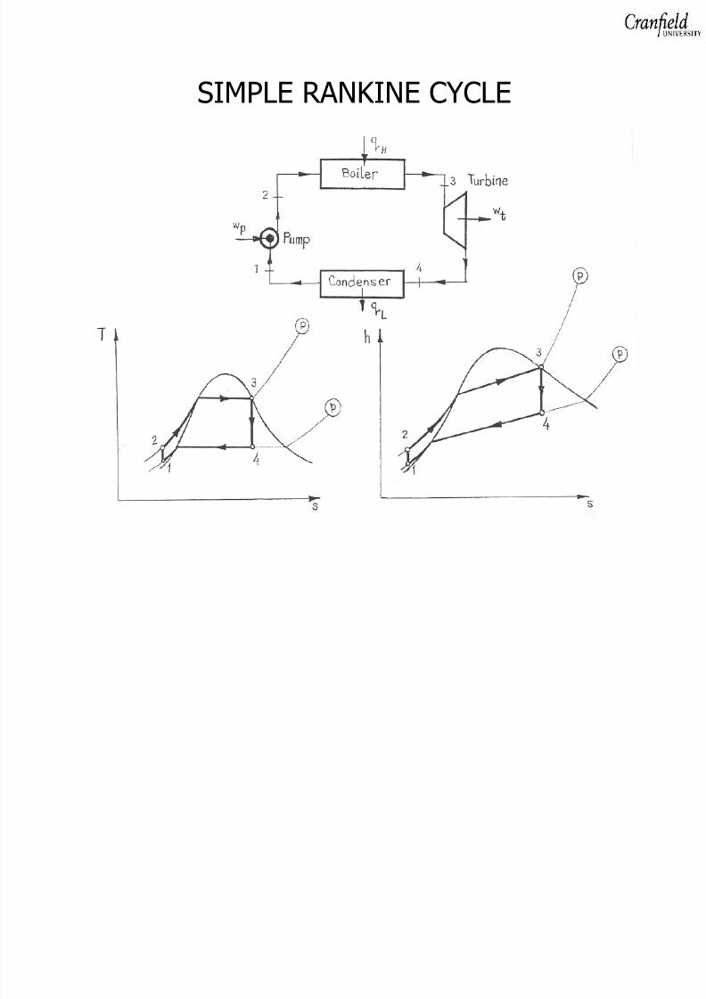
SIMPLE RANKINE CYCLE
8/8/2019 Analysis of Steam Power Plants OB 2010
http://slidepdf.com/reader/full/analysis-of-steam-power-plants-ob-2010 11/57

8/8/2019 Analysis of Steam Power Plants OB 2010
http://slidepdf.com/reader/full/analysis-of-steam-power-plants-ob-2010 12/57
Steam turbine-generator set at a coal-fired power plant, Germany
8/8/2019 Analysis of Steam Power Plants OB 2010
http://slidepdf.com/reader/full/analysis-of-steam-power-plants-ob-2010 13/57
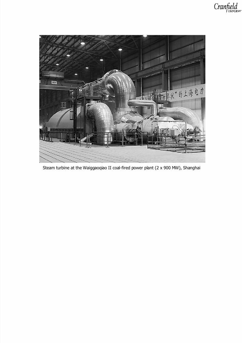
Steam turbine at the Waiggaoqiao II coal-fired power plant (2 x 900 MW), Shanghai
8/8/2019 Analysis of Steam Power Plants OB 2010
http://slidepdf.com/reader/full/analysis-of-steam-power-plants-ob-2010 14/57
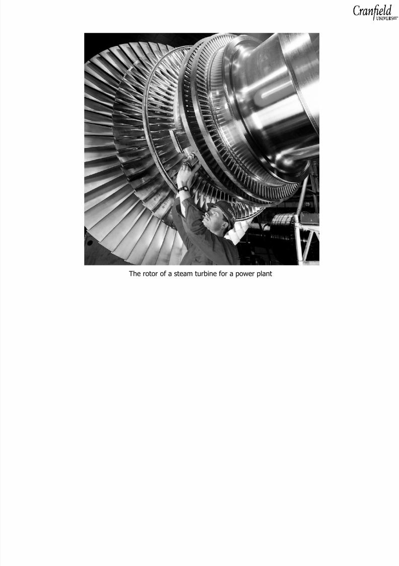
The rotor of a steam turbine for a power plant

8/8/2019 Analysis of Steam Power Plants OB 2010
http://slidepdf.com/reader/full/analysis-of-steam-power-plants-ob-2010 15/57
Steam turbine at for a 500 MW supercritical coal-fired unit at Genesse Power Generatng Plant , Canada
8/8/2019 Analysis of Steam Power Plants OB 2010
http://slidepdf.com/reader/full/analysis-of-steam-power-plants-ob-2010 16/57
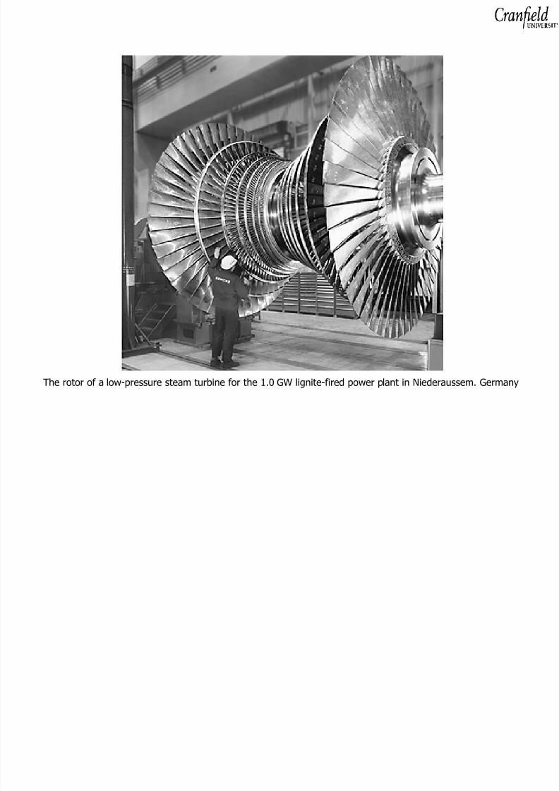
The rotor of a low-pressure steam turbine for the 1.0 GW lignite-fired power plant in Niederaussem. Germany

8/8/2019 Analysis of Steam Power Plants OB 2010
http://slidepdf.com/reader/full/analysis-of-steam-power-plants-ob-2010 17/57
Steam turbine at Civaux nuclear power plant, France

8/8/2019 Analysis of Steam Power Plants OB 2010
http://slidepdf.com/reader/full/analysis-of-steam-power-plants-ob-2010 18/57
The first-law analysis of the Rankine cycle, based on a steady-flow of a unitmass of the working fluid and neglecting changes in kinetic and potentialenergies, leads to the following information:
Heat added in the boiler q H = q 2-3 = h 3 − h2
Work developed by the turbine w t = w 3-4 = h 3 − h4
Heat rejected in the condenser q L = q 4-1 = h 1 − h4
Work input to the feed pump w p = w 1-2 = h 1 − h2
Having no tabular or graphical equation-of-state information for the subcooled(or compressed ) liquid water , it may be treated as an incompressiblefluid and the work input to the pump may be estimated as:
2w
p= h
1− h
2= − ∫ v dp = v
1(p
1− p
2)
1
8/8/2019 Analysis of Steam Power Plants OB 2010
http://slidepdf.com/reader/full/analysis-of-steam-power-plants-ob-2010 19/57
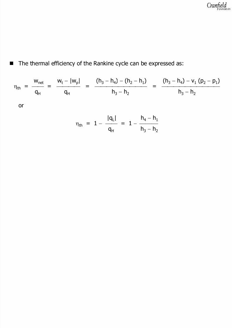
The thermal efficiency of the Rankine cycle can be expressed as:
wnet wt − |w p| (h 3 − h4) − (h 2 − h1) (h 3 − h4) − v1 (p 2 − p1)ηth = = = =
qH qH h3 − h2 h3 − h2
or
|q L| h 4 − h1
ηth = 1 − = 1 − qH h3 − h2
8/8/2019 Analysis of Steam Power Plants OB 2010
http://slidepdf.com/reader/full/analysis-of-steam-power-plants-ob-2010 20/57
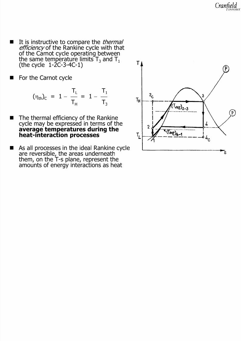
It is instructive to compare the thermal efficiency of the Rankine cycle with thatof the Carnot cycle operating betweenthe same temperature limits T 3 and T 1
(the cycle 1-2C-3-4C-1)
For the Carnot cycle
TL T1
(ηth)C = 1 − = 1 − TH T3
The thermal efficiency of the Rankinecycle may be expressed in terms of theaverage temperatures during theheat-interaction processes
As all processes in the ideal Rankine cycleare reversible, the areas underneaththem, on the T-s plane, represent theamounts of energy interactions as heat
8/8/2019 Analysis of Steam Power Plants OB 2010
http://slidepdf.com/reader/full/analysis-of-steam-power-plants-ob-2010 21/57
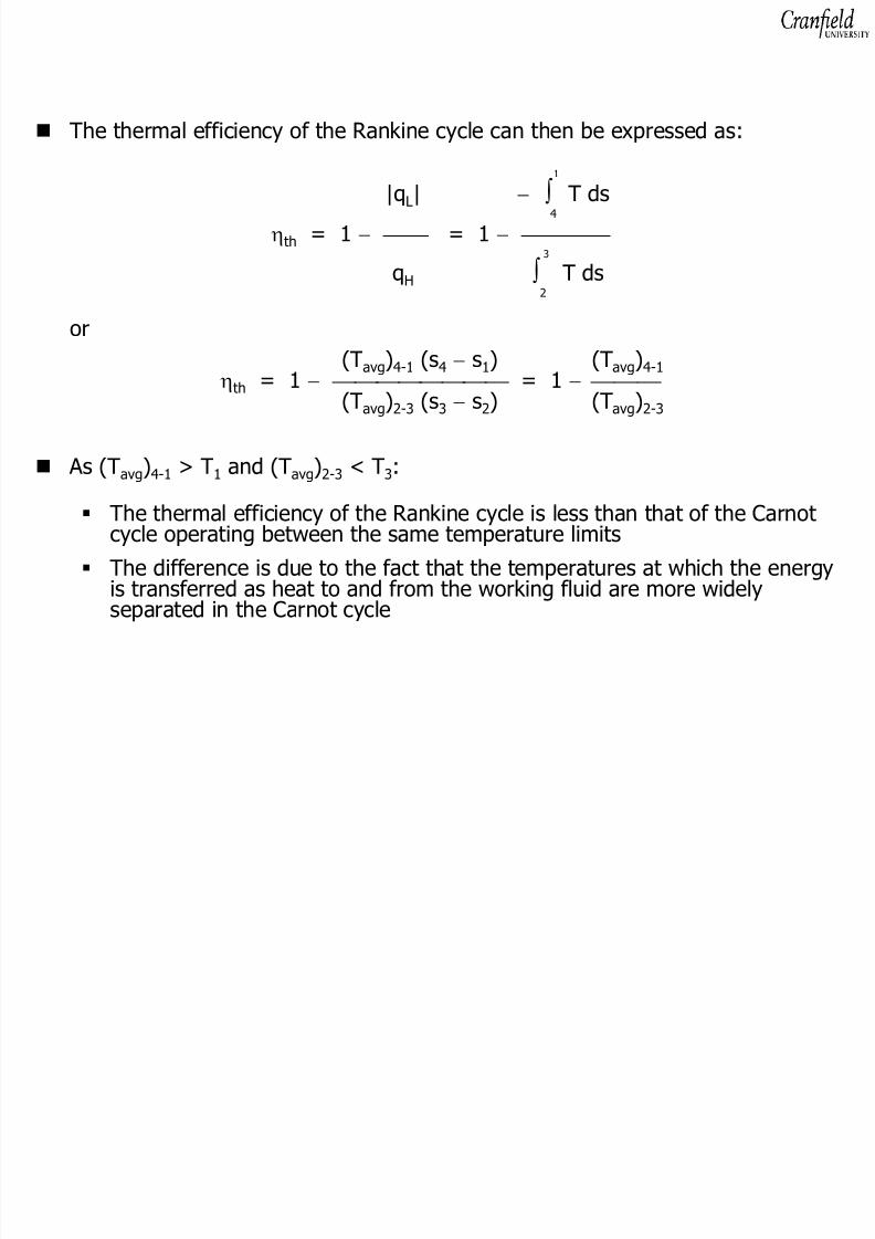
The thermal efficiency of the Rankine cycle can then be expressed as:
1
|q L| − ∫ T ds4
ηth = 1 − = 1 − 3
qH ∫ T ds2
or(Tavg )4-1 (s 4 − s1) (T avg )4-1ηth = 1 − = 1 − (Tavg )2-3 (s 3 − s2) (T avg )2-3
As (T avg )4-1 > T 1 and (T avg )2-3 < T 3:
The thermal efficiency of the Rankine cycle is less than that of the Carnotcycle operating between the same temperature limits
The difference is due to the fact that the temperatures at which the energyis transferred as heat to and from the working fluid are more widelyseparated in the Carnot cycle

8/8/2019 Analysis of Steam Power Plants OB 2010
http://slidepdf.com/reader/full/analysis-of-steam-power-plants-ob-2010 22/57
For improving the thermal efficiency of the simple Rankine cycle, it isdesirable to:
add the heat to the working fluid at the highest possible averagetemperature and remove it at the lowest possible averagetemperature

8/8/2019 Analysis of Steam Power Plants OB 2010
http://slidepdf.com/reader/full/analysis-of-steam-power-plants-ob-2010 23/57
Operate the condenser at a reduced pressure
This would not affect the energy addition in the boiler
A larger enthalpy drop can be obtained in the turbine, increasing the turbinepower output
The reduction of the condenser pressure will result in a modest increase inthe power requirement of the feed pump
A lower limit to the condensing temperature is set by the inlet temperatureof the cooling medium circulating in the condenser and the economic size of the condenser
In power plants, river- or sea-water are usually used as the cooling mediumin the condenser and Cooling towers are used to cool the circulatingwater when water supplies are restricted
The condensing temperature may be made to approach more closely thecirculating-water inlet temperature by providing greater surface area forcondensation and a greater flow rate of circulating water in the condenser

8/8/2019 Analysis of Steam Power Plants OB 2010
http://slidepdf.com/reader/full/analysis-of-steam-power-plants-ob-2010 24/57
Addition of superheating
The extra energy input would permitthe system's operation with a higherturbine inlet enthalpy
As the lines of constant pressure(isobars) diverge on the h-s plane, the
enthalpy drop across the turbine and itspower output increase
Additional energy as heat have to besupplied in the boiler, which offsets thepower gain
Rankine-cycle power plants, using fossilfuels as the primary energy source,usually employ superheat
In this way, a better match ensuesbetween the hot products of combustion and the water in the boiler

8/8/2019 Analysis of Steam Power Plants OB 2010
http://slidepdf.com/reader/full/analysis-of-steam-power-plants-ob-2010 25/57

8/8/2019 Analysis of Steam Power Plants OB 2010
http://slidepdf.com/reader/full/analysis-of-steam-power-plants-ob-2010 26/57
Raising the boiler pressure
This is accompanied by an increase in the working-fluid’s saturationtemperature during the heat-addition process
Leads to an increase in the wetness of steam at the turbine exhaust, whichhas adverse effects on its efficiency and life-time
A modest increase in the power requirement of the deed pump would ensue
8/8/2019 Analysis of Steam Power Plants OB 2010
http://slidepdf.com/reader/full/analysis-of-steam-power-plants-ob-2010 27/57
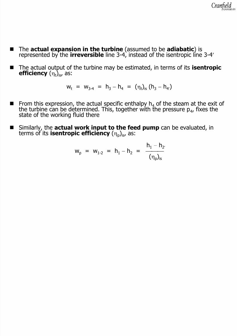
The actual expansion in the turbine (assumed to be adiabatic ) isrepresented by the irreversible line 3-4, instead of the isentropic line 3-4 ′
The actual output of the turbine may be estimated, in terms of its isentropicefficiency (ηt) is, as:
wt = w 3-4 = h 3 − h4 = ( ηt) is (h 3 − h4′)
From this expression, the actual specific enthalpy h 4 of the steam at the exit of the turbine can be determined. This, together with the pressure p 4, fixes thestate of the working fluid there
Similarly, the actual work input to the feed pump can be evaluated, interms of its isentropic efficiency (ηp) is, as:
h1 − h2′wp = w 1-2 = h 1 − h2 =
(ηp) is
8/8/2019 Analysis of Steam Power Plants OB 2010
http://slidepdf.com/reader/full/analysis-of-steam-power-plants-ob-2010 28/57
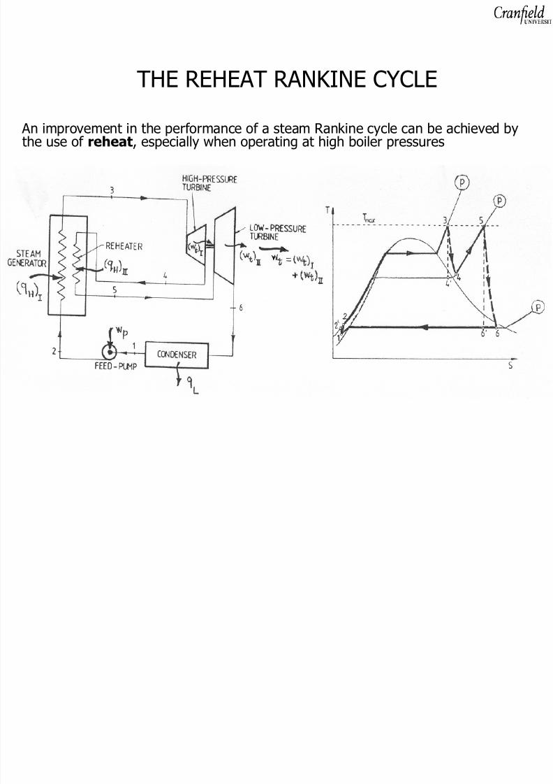
THE REHEAT RANKINE CYCLE
An improvement in the performance of a steam Rankine cycle can be achieved bythe use of reheat , especially when operating at high boiler pressures
8/8/2019 Analysis of Steam Power Plants OB 2010
http://slidepdf.com/reader/full/analysis-of-steam-power-plants-ob-2010 29/57
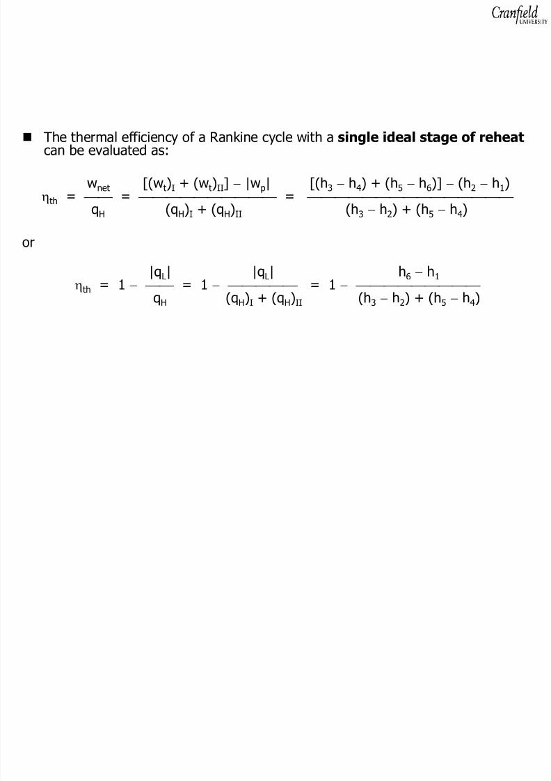
The thermal efficiency of a Rankine cycle with a single ideal stage of reheatcan be evaluated as:
wnet [(w t)I + (w t)II] − |w p| [(h 3 − h4) + (h 5 − h6)] − (h 2 − h1)ηth = = =
qH (q H)I + (q H)II (h 3 − h2) + (h 5 − h4)
or
|q L| |q L| h 6 − h1ηth
= 1 − = 1 − = 1 − qH (q H)I + (q H)II (h 3 − h2) + (h 5 − h4)

8/8/2019 Analysis of Steam Power Plants OB 2010
http://slidepdf.com/reader/full/analysis-of-steam-power-plants-ob-2010 30/57
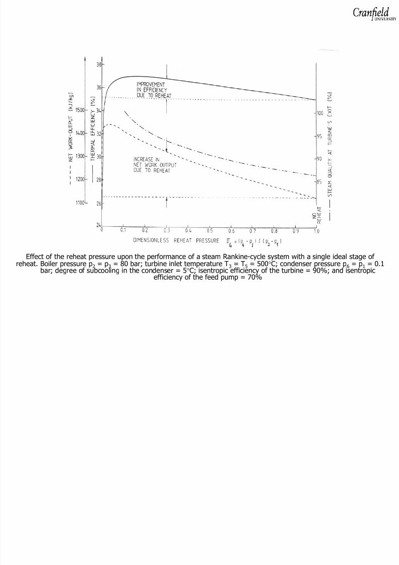
Reheating increases the average effective temperature at which heat is suppliedto the working fluid, and can result in an improvement in the thermal efficiencyof the cycle
Although the net work output of the reheat cycle is more than that of the simpleRankine cycle, more energy as heat is expended in the reheat cycle
Improvement in thermal efficiency depends on the operating conditions of thesystem
The most significant benefit of using reheat is the drier steam obtained at theexhaust of the turbine

8/8/2019 Analysis of Steam Power Plants OB 2010
http://slidepdf.com/reader/full/analysis-of-steam-power-plants-ob-2010 31/57
Modern steam power-plants employ at least a single stage of reheat; someemploy two
More than two stages results in cycle complications and increased capital coststhat are not justified by improvements in thermal efficiency
The reheat cycle has the particular disadvantage that the same amount of flowis circulating through the entire system (the size of the low-pressure turbinestage is considerably larger than that of the high-pressure stage ,
disproportionally so with regard to its power output per unit cost)
8/8/2019 Analysis of Steam Power Plants OB 2010
http://slidepdf.com/reader/full/analysis-of-steam-power-plants-ob-2010 32/57
Effect of the reheat pressure upon the performance of a steam Rankine-cycle system with a single ideal stage of
reheat. Boiler pressure p 2 = p 3 = 80 bar; turbine inlet temperature T 3 = T 5 = 500 °C; condenser pressure p 6 = p 1 = 0.1bar; degree of subcooling in the condenser = 5 °C; isentropic efficiency of the turbine = 90%; and isentropicefficiency of the feed pump = 70%

8/8/2019 Analysis of Steam Power Plants OB 2010
http://slidepdf.com/reader/full/analysis-of-steam-power-plants-ob-2010 33/57
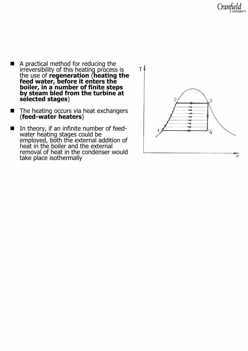
THE REGENERATIVE RANKINE CYCLE
The regenerative cycle is another modification of the Rankine cycle, whichresults in a considerable improvement in thermal efficiency
In simple cycles, the feed water enters the boiler at a temperature well below
the saturation temperature corresponding to the boiler pressureThe initial heating process in the boiler to raise the temperature of liquid waterto the saturation temperature constitutes a major irreversibility in the cycle(large temperature difference between the products of combustion and theliquid water)
This relatively low-temperature heat-addition process greatly reduces thethermal efficiency of the cycle
If the average temperature of this portion of the heat-addition
process could be raised , the thermal efficiency of the cycle wouldmore nearly approach that of the Carnot cycle
8/8/2019 Analysis of Steam Power Plants OB 2010
http://slidepdf.com/reader/full/analysis-of-steam-power-plants-ob-2010 34/57

8/8/2019 Analysis of Steam Power Plants OB 2010
http://slidepdf.com/reader/full/analysis-of-steam-power-plants-ob-2010 35/57
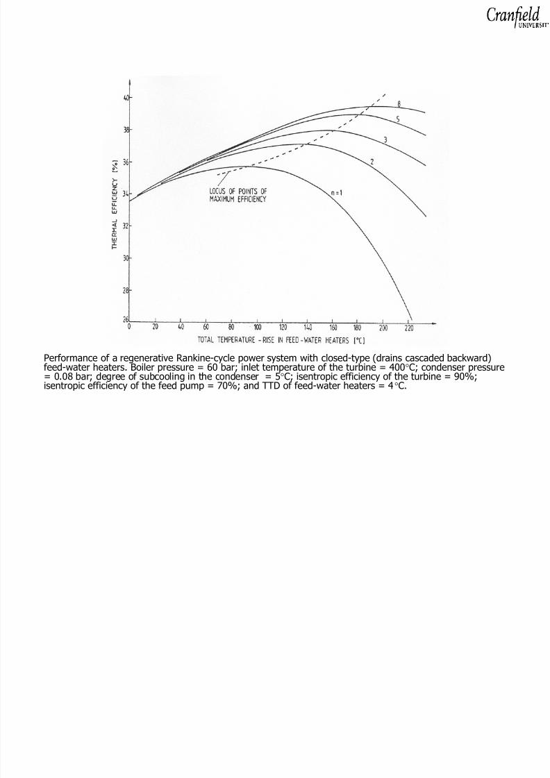
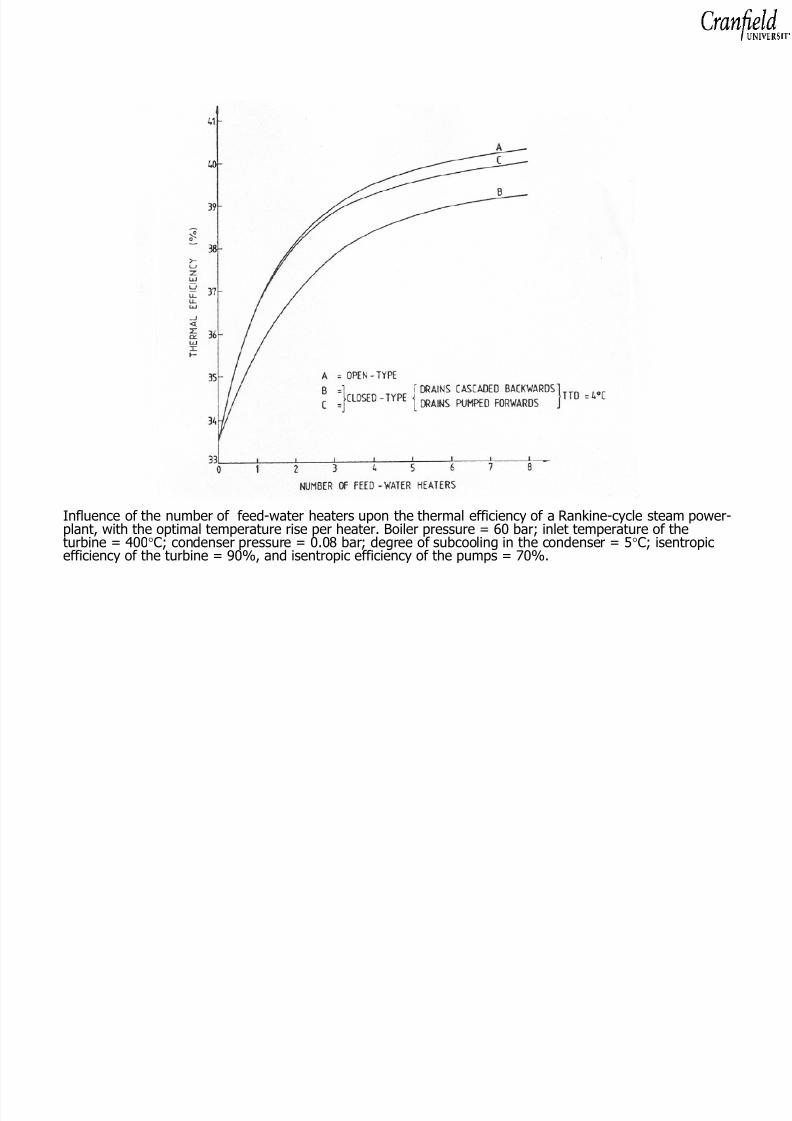
As the number of feed-water heating stages increases, the difference intemperature between the extracted steam and the feed water in each feed-water heater decreases such that the heat-exchange process could be assumed
to take place reversiblyThe performance of this limiting system is that of a Carnot cycle
Modern large steam power plants employ between five and eight feed-waterheating stages
8/8/2019 Analysis of Steam Power Plants OB 2010
http://slidepdf.com/reader/full/analysis-of-steam-power-plants-ob-2010 36/57
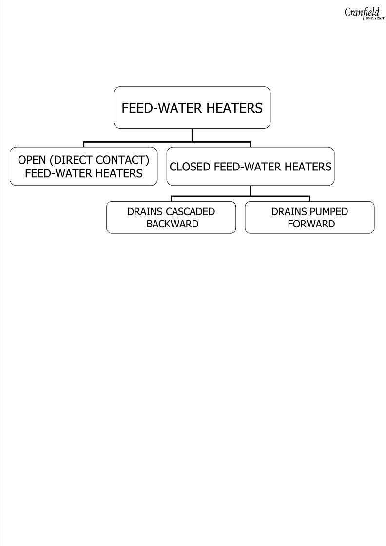
FEED-WATER HEATERS
OPEN (DIRECT CONTACT)FEED-WATER HEATERS CLOSED FEED-WATER HEATERS
DRAINS CASCADEDBACKWARD
DRAINS PUMPEDFORWARD

8/8/2019 Analysis of Steam Power Plants OB 2010
http://slidepdf.com/reader/full/analysis-of-steam-power-plants-ob-2010 37/57
Open (or Direct-Contact) Feed-Water Heaters
In an open feed-water heater, the steam extracted from the turbine ismixed directly with the incoming subcooled feed water to produce,ideally , saturated liquid water at the pressure of the extracted steam
To prevent the occurrence of cavitation in the feed-water pumps, it is preferablein practice to limit the mass of the extracted steam so that the water wouldemerge subcooled from the feed-water heater
Open-type feed-water heaters also serve as dearators (the break-up of waterduring the mixing process helps in increasing the surface area and liberatesdissolved, non-condensable gases that can be vented to the atmosphere)

8/8/2019 Analysis of Steam Power Plants OB 2010
http://slidepdf.com/reader/full/analysis-of-steam-power-plants-ob-2010 38/57
An ideal steam Rankine power system with two stages of open-type feed-water heaters
8/8/2019 Analysis of Steam Power Plants OB 2010
http://slidepdf.com/reader/full/analysis-of-steam-power-plants-ob-2010 39/57

8/8/2019 Analysis of Steam Power Plants OB 2010
http://slidepdf.com/reader/full/analysis-of-steam-power-plants-ob-2010 40/57
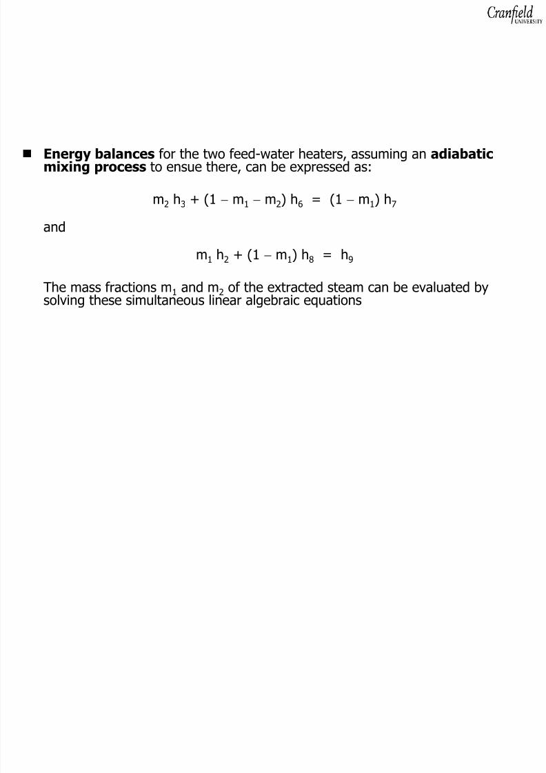
The performance parameters of the cycle can be estimated, per unit mass of steam entering the turbine, as:
Heat added in the boiler q H = h 1 − h10
Output work of the turbine w t = (h 1 − h2) + (1 − m1) (h 2 − h3)+ (1 − m1 − m2) (h 3 − h4)
Total pumping work |w p| = (1 − m1 − m2) (h 6 − h5)
+ (1 − m1) (h 8 − h7) + (h 10 − h9)
Heat rejected in the condenser |q L| = (1 − m1 − m2) (h 4 − h5)

8/8/2019 Analysis of Steam Power Plants OB 2010
http://slidepdf.com/reader/full/analysis-of-steam-power-plants-ob-2010 41/57
Closed-Type Feed-Water Heaters
Closed-type of feed-water heater are the simplest and most commonly usedtype in power plants
They are normally shell-and-tube heat exchangers , with the feed waterflowing inside the tubes and the steam extracted on the shell side (smallcondensers that operate at pressures higher the main-plant condenser)
As the feed water flows inside the tubes of successive feed-water heaters,without mixing with the bled steam, the condensate is pressurised only oncewith a pump that serves simultaneously as a boiler feed pump
In practice, a condensate pump and a boiler feed pump (placed downstream of the feed-water heaters) are often used in order to limit the pressure rise in eachpump

8/8/2019 Analysis of Steam Power Plants OB 2010
http://slidepdf.com/reader/full/analysis-of-steam-power-plants-ob-2010 42/57
The temperature of the feed water at the exit from a closed-type feed-waterheater cannot reach the inlet temperature of the bled steam
A terminal temperature difference (TTD) of between 4 and 6 °C ismaintained practically by the proper design of the heater
The TTD is prescribed as the difference between the saturationtemperature of the bled steam at the extraction pressure and theoutlet temperature of the feed water from the heater

8/8/2019 Analysis of Steam Power Plants OB 2010
http://slidepdf.com/reader/full/analysis-of-steam-power-plants-ob-2010 43/57
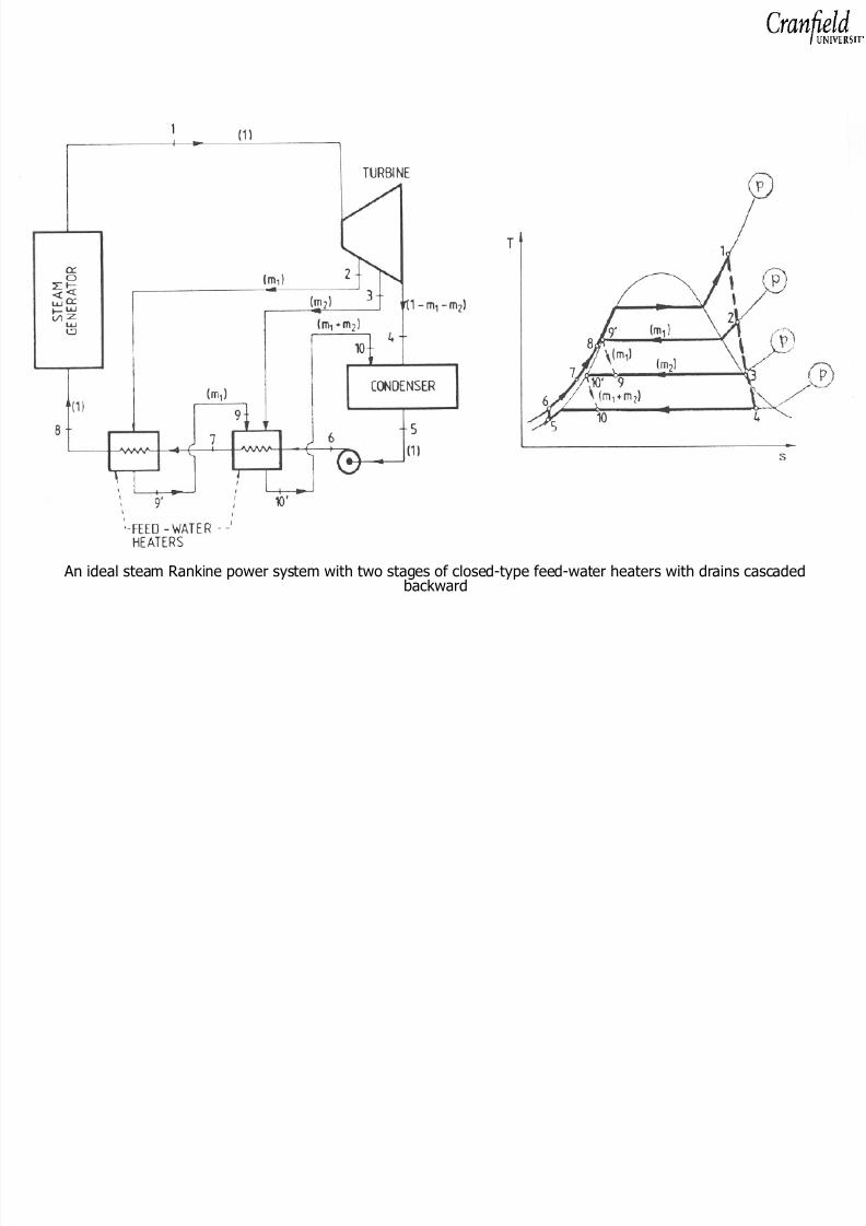
Closed-Type Feed-Water Heaters with the Drains Cascaded Backward
The bled steam condenses in a feed-water heater after transferring part of itsenergy to the feed water
The condensate ( drain ) from this heater, which might be saturated or slightlysubcooled liquid water, is then throttled backward to the next lower-pressurefeed-water heater
Throttling is an irreversible , constant-enthalpy (isoenthalpic ) pressure-
reduction processThe drain of the lowest pressure feed-water heater is led back, with a loss inthe available energy, to the main condenser
8/8/2019 Analysis of Steam Power Plants OB 2010
http://slidepdf.com/reader/full/analysis-of-steam-power-plants-ob-2010 44/57
An ideal steam Rankine power system with two stages of closed-type feed-water heaters with drains cascadedbackward
8/8/2019 Analysis of Steam Power Plants OB 2010
http://slidepdf.com/reader/full/analysis-of-steam-power-plants-ob-2010 45/57
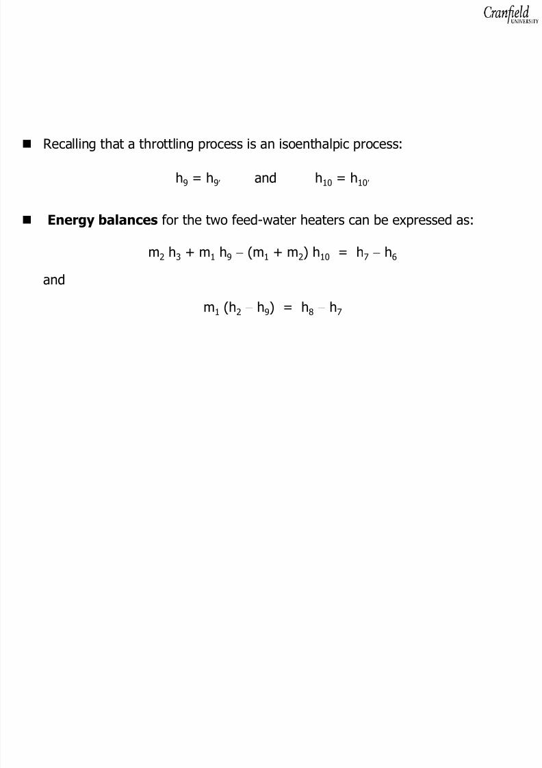
Recalling that a throttling process is an isoenthalpic process:
h9 = h 9′ and h 10 = h 10 ′
Energy balances for the two feed-water heaters can be expressed as:
m2 h3 + m 1 h9 − (m 1 + m 2) h 10 = h 7 − h6
and
m1 (h 2 − h9) = h 8 − h7
8/8/2019 Analysis of Steam Power Plants OB 2010
http://slidepdf.com/reader/full/analysis-of-steam-power-plants-ob-2010 46/57
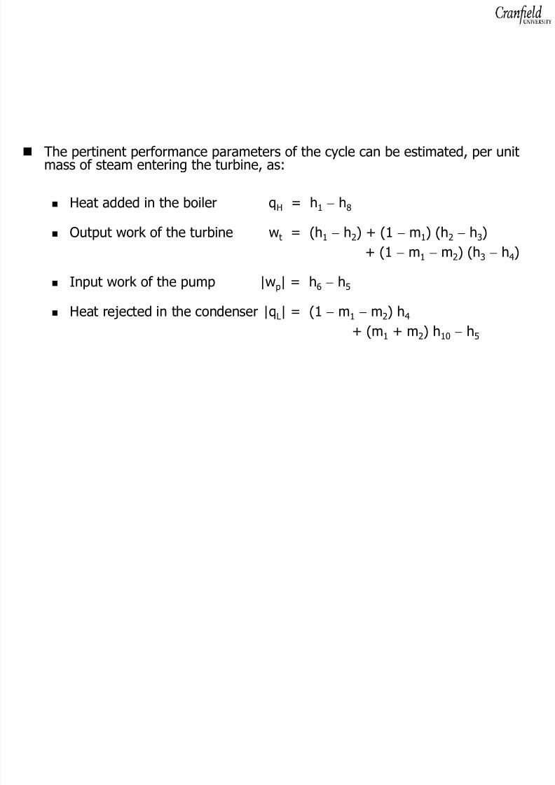
The pertinent performance parameters of the cycle can be estimated, per unitmass of steam entering the turbine, as:
Heat added in the boiler q H = h 1 − h8
Output work of the turbine w t = (h 1 − h2) + (1 − m1) (h 2 − h3)+ (1 − m1 − m2) (h 3 − h4)
Input work of the pump |w p| = h 6 − h5
Heat rejected in the condenser |q L| = (1 − m1 − m2) h 4
+ (m 1 + m 2) h 10 − h5

8/8/2019 Analysis of Steam Power Plants OB 2010
http://slidepdf.com/reader/full/analysis-of-steam-power-plants-ob-2010 47/57

8/8/2019 Analysis of Steam Power Plants OB 2010
http://slidepdf.com/reader/full/analysis-of-steam-power-plants-ob-2010 48/57
An ideal steam Rankine power system with two stages of closed-type feed-water heaters with drains pumped forward

8/8/2019 Analysis of Steam Power Plants OB 2010
http://slidepdf.com/reader/full/analysis-of-steam-power-plants-ob-2010 49/57
The drain from a heater is assumed to mix adiabatically with the feed water in themain line downstream of that heater:
(1 − m1) h 13 = (1 − m1 − m2) h 7 + m 2 h12
and
h14 = (1 − m1) h 8 + m 1 h11
Energy balances of the two feed-water heaters can be expressed as:
m2 (h 3 − h10) = (1 − m1 − m2) (h 7 − h6)
and
m1 (h 2 − h9) = (1 − m1) (h 8 − h13)

8/8/2019 Analysis of Steam Power Plants OB 2010
http://slidepdf.com/reader/full/analysis-of-steam-power-plants-ob-2010 50/57
The performance parameters of the cycle can now be estimated, per unit mass of steam entering the turbine, as:
Heat added in the boiler q H = h 1 − h14
Output work of the turbine w t = (h 1 − h2) + (1 − m1) (h 2 − h3)+ (1 − m1 − m2) (h 3 − h4)
Total pumping work |w p| = (1 − m1 − m2) (h 6 − h5)
+ m 2 (h 12 − h10) + m 1 (h 11 − h9)
Heat rejected in the condenser |q L| = (1 − m1 − m2) (h 4 − h5)

8/8/2019 Analysis of Steam Power Plants OB 2010
http://slidepdf.com/reader/full/analysis-of-steam-power-plants-ob-2010 51/57
Choice of the Type and Placement of Feed-Water Heaters
In general, the choice of feed-water heater type depends upon many factors,including:
Designer optimisationPractical considerationsCost
Accordingly, there are a variety of cycle designs

8/8/2019 Analysis of Steam Power Plants OB 2010
http://slidepdf.com/reader/full/analysis-of-steam-power-plants-ob-2010 52/57
There are features that are, however, rather common:
One open-type feed-water heater , which doubles as a dearator , isusually placed near the middle of the feed-water heating system, where thetemperature is most conducive to the release of non-condensable gases
Because of its simplicity, the closed-type feed-water heater with thedrains cascaded backward is the most-common type, used before andafter the dearator heater
One closed feed-water heater with the drains pumped forward is
often used as the lowest-pressure feed-water heater to pump all theaccumulating drains back into the main feed-water line

8/8/2019 Analysis of Steam Power Plants OB 2010
http://slidepdf.com/reader/full/analysis-of-steam-power-plants-ob-2010 53/57
Pressures at which steam is to be bled from the turbine, in order to achieve themaximum increase in the thermal efficiency of the Rankine-cycle system, can beevaluated by a complete optimisation of the cycle
Such a task entails the use of large, complex and usually not readily-availablecomputer models
Design considerations might impose certain constrains on the selection of theoptimal extraction points

8/8/2019 Analysis of Steam Power Plants OB 2010
http://slidepdf.com/reader/full/analysis-of-steam-power-plants-ob-2010 54/57
A simple selection criterion is usually employed in practice: equal temperaturerises are to be achieved in the feed-water heaters , with the optimaltemperature rise per heater , ( ∆T)opt , given by
(Ts)B − (Ts)C
(∆T)opt = n + 1
(Ts)B saturation temperature of the steam corresponding to the boiler pressure
(Ts)C saturation temperature of the steam corresponding to the condenserpressuren number of the feed-water heaters employed
8/8/2019 Analysis of Steam Power Plants OB 2010
http://slidepdf.com/reader/full/analysis-of-steam-power-plants-ob-2010 55/57
8/8/2019 Analysis of Steam Power Plants OB 2010
http://slidepdf.com/reader/full/analysis-of-steam-power-plants-ob-2010 56/57

8/8/2019 Analysis of Steam Power Plants OB 2010
http://slidepdf.com/reader/full/analysis-of-steam-power-plants-ob-2010 57/57