Embed Size (px)
Citation preview

1
KAUNAS UNIVERSITY OF TECHNOLOGY
FACULTY OF MECHANICAL ENGINEERING AND DESIGN
DEPARTMENT OF PRODUCTION ENGINEERING
Vitalijus Grižauskas
ANALYSIS OF SOLID FUEL BOILER DESIGN
FOR PERFORMANCE COEFFICIENT
IMPROVEMENT
Final project for Master degree
Academic supervisor:
Assoc. Prof. Dr. M. Rimašauskas
Kaunas, 2015

2
KAUNAS UNIVERSITY OF TECHNOLOGY
FACULTY OF MECHANICAL ENGINEERING AND DESIGN
DEPARTMENT OF PRODUCTION ENGINEERING
ANALYSIS OF SOLID FUEL BOILER DESIGN FOR
PERFORMANCE COEFFICIENT IMPROVEMENT
Final project for Master degree
Prepared by Stud. Vitalijus Grižauskas, MEM 3/9
Supervisor Assoc. Prof. Dr. Marius Rimašauskas
Reviewer Assoc. Prof. Dr. Sigitas Kilikevičius
KAUNAS, 2015
(Signature) (Date)
(Signature) (Date)
(Signature) (Date)

3
KAUNAS UNIVERSITY OF TECHNOLOGY
FACULTY OF MECHANICAL ENGINEERING AND DESIGN
DEPARTMENT OF PRODUCTION ENGINEERING
(Faculty)
Vitalijus Grižauskas
(Student's name, surname)
621H77003 Industrial Engineering and Management
(Title and code of study programme)
Analysis of solid fuel boiler design for performance
coefficient improvement
DECLARATION OF ACADEMIC HONESTY
29 May 2015
Kaunas
I confirm that a final project by me, Vitalijus Grižauskas, on the subject “Analysis of
solid fuel boiler design for performance coefficient improvement" is written completely by
myself; all provided data and research results are correct and obtained honestly. None of the
parts of this thesis have been plagiarized from any printed or Internet sources, all direct and
indirect quotations from other resources are indicated in literature references. No monetary
amounts not provided for by law have been paid to anyone for this thesis.
I understand that in case of a resurfaced fact of dishonesty penalties will be applied to
me according to the procedure effective at Kaunas University of Technology.
(name and surname filled in by hand) (signature)

4
Grižauskas, V. Kieto kuro katilo konstrukcijos analizė naudingumo koeficiento
gerinimui. Magistrantūros studijų baigiamojo darbo vadovas Assoc. Prof. Dr. Marius
Rimašauskas; Kauno Technologijos Universitetas, mechanikos inžinerijos ir dizaino
fakultetas, gamybos inžinerijos katedra.
Kaunas, 2015. 53 p.
SANTRAUKA
Įvadiniame magistro darbo skyriuje pateiktas temos aktualumas, darbo tikslas (lengvai
naudojamo 3D katilo modelio sukūrimas ir testavimas.
Pirmajame skyriuje išnagrinėti pramoninių katilų variantai bei jų panaudojimo būdai
kasdieniniame gyvenime, darbo principas ir pateikti keli aspektai susieję su katilo saugumu.
Antrajame skyriuje aprašomi katilo efektyvumo principai ir pateiktos esamo tiriamo
gaminio technines charakteristikos kartu su katilo pajungimo schema ir jos veikimo principu.
Malkomis kūrenamas kietojo kuro vandens šildymo katilas skirtas įvairios paskirties pastatų,
su uždara šildymo sistema, šildymui ir karšto vandens ruošimui
Trečiame ir ketvirtame skyriuose pateikti naujajam katilo modeliui visi siūlomi
atnaujinimai su 3D CAD vaizdais, bei katilo atliktųjų testų naudingumo koeficiento ir kiti
reikalaujamų bandymų parametrai. Katilas buvo išbandytas pagal LST EN 303-5 standarte
nurodytus bandymų metodus padedantis nustatyti katilo šiluminė galia bei padės išaiškinti
degimo produktų CO,CO2 koncentracijas.
Penktąjį skyrių sudaro abiejų katilų išlaidu sąrašai kurie parado ant kiek skiriasi senojo
bei naujojo katilų išlaidu elementai, pridėtine verte it gamykline savikaina.
Išvadose apibendrinami pasiekti rezultatai ir gauta informacija apie naująjį katilo B-
25E modelio eksploatacinės savybes .

5
Grižauskas, V. Analysis of solid fuel boiler design for performance coefficient
improvement. Master degree final project supervisor Assoc. Prof. Dr. Marius Rimašauskas;
Kaunas University of Technology, faculty of Mechanical Engineering and Design,
Department of Production Engineering.
Kaunas, 2015. 53 p.
SUMMARY
In the introductory chapter of the master work the importance of the theme is presented
as well as the aim of the work (development of 3D CAD model of the boiler and its testing)
The first chapter industrial boiler types are presented and their use in everyday life,
their work principal and a few aspects considering safety issues.
The second chapter shows the boiler efficiency principals are shown as well as the
technical characteristics of the experiment boiler version is presented along with the heating
system and the work principle of a heating boiler fired with wood logs designed for heating
various premises with closed heating systems and for production of domestic hot water
The third and fourth chapters present new upgrades for the boiler with 3D CAD model,
as well as all the test results that were performed which show the boiler performance
coefficient and other required parameters. The boiler was tested according to the LST EN
303-5 standards, by which the boilers thermal power and the concentrations of CO, CO2 will
be shown.
The fifth chapter contains list of expenses of both new and old boilers, which show all
the expense elements, factory costs and added value of both products.
The conclusions summarize results of the tests and received information about the new
B-25E boiler performance.
6
KAUNO TECHNOLOGIJOS UNIVERSITETAS
MECHANIKOS INŽINERIJOS IR DIZAINO FAKULTETAS
Tvirtinu:
Gamybos inžinerijos (parašas, data)
katedros vedėjas
(vardas, pavardė)
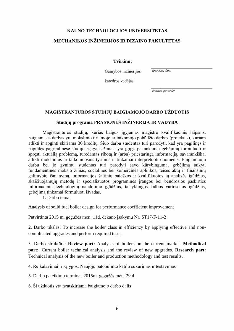
MAGISTRANTŪROS STUDIJŲ BAIGIAMOJO DARBO UŽDUOTIS
Studijų programa PRAMONĖS INŽINERIJA IR VADYBA
Magistrantūros studijų, kurias baigus įgyjamas magistro kvalifikacinis laipsnis,
baigiamasis darbas yra mokslinio tiriamojo ar taikomojo pobūdžio darbas (projektas), kuriam
atlikti ir apginti skiriama 30 kreditų. Šiuo darbu studentas turi parodyti, kad yra pagilinęs ir
papildęs pagrindinėse studijose įgytas žinias, yra įgijęs pakankamai gebėjimų formuluoti ir
spręsti aktualią problemą, turėdamas ribotą ir (arba) prieštaringą informaciją, savarankiškai
atlikti mokslinius ar taikomuosius tyrimus ir tinkamai interpretuoti duomenis. Baigiamuoju
darbu bei jo gynimu studentas turi parodyti savo kūrybingumą, gebėjimą taikyti
fundamentines mokslo žinias, socialinės bei komercinės aplinkos, teisės aktų ir finansinių
galimybių išmanymą, informacijos šaltinių paieškos ir kvalifikuotos jų analizės įgūdžius,
skaičiuojamųjų metodų ir specializuotos programinės įrangos bei bendrosios paskirties
informacinių technologijų naudojimo įgūdžius, taisyklingos kalbos vartosenos įgūdžius,
gebėjimą tinkamai formuluoti išvadas.
1. Darbo tema:
Analysis of solid fuel boiler design for performance coefficient improvement
Patvirtinta 2015 m. gegužės mėn. 11d. dekano įsakymu Nr. ST17-F-11-2
2. Darbo tikslas: To increase the boiler class in efficiency by applying effective and non-
complicated upgrades and perform required tests.
3. Darbo struktūra: Review part: Analysis of boilers on the current market. Methodical
part:. Current boiler technical analysis and the review of new upgrades. Research part:
Technical analysis of the new boiler and production methodology and test results.
4. Reikalavimai ir sąlygos: Naujojo patobulinto katilo sukūrimas ir testavimas
5. Darbo pateikimo terminas 2015m. gegužės mėn. 29 d.
6. Ši užduotis yra neatskiriama baigiamojo darbo dalis

7
Išduota studentui Vitalijui Grižauskui
Užduotį gavau Vitalijus Grižauskas
(studento vardas, pavardė) (parašas, data)
Vadovas Assoc. Prof. Dr. M.Rimašauskas
(pareigos, vardas, pavardė) (parašas, data)

8
Table of Contents
Introduction………………………………………………………………………………...….9
1. DESIGN OVERVIEW OF AN INDUSTRIAL BOILER………………………………...11
1.1 Operation principle of industrial heating boilers……………………………………….12
1.2 Use of boiler systems in everyday practice………………………………………….…14
1.3 Safety issues……………………………………………………………………………16
2. TECHNICAL DATA AND WORKING SCHEME OF THE CURRENT HEATING
BOILER...................................................................................................................................17
2.1 Technical data………………………………………………………………………......17
2.2 Current boiler working scheme and house heating system……………………………..18
2.3 Efficiency……………………………………………………………………………….20
2.4 CAD view of the proposed new boiler………………………………………………….22
3. TECHNICAL UPGRADES……………………………………………………………….23
3.1 Regulation of primary and secondary air supply……………………………………….23
3.2 Separately assembled chimney and turbulence plates……………………………….…27
3.3 Additional upgrades……………………………………………………………………29
4. TESTING RESULTS OF THE NEW UPGRADED BOILER……………………….......33
4.1 Test objective description and characteristics………………………………………….34
4.2 Environmental conditions during the tests……………………………………………..36
4.3 Test equipment and measuring instruments……………………………………………36
4.4 Test fuel……………………………………………………………………………...…37
4.5 Test results……………………………………………………………………………...38
4.6 Electrical consumption…………………………………………………………………45
4.7 Waterside resistance……………………………………………………………………46
5. COST ANALYSIS………..………………………………………………………...….…49
CONCLUSIONS……………….…………………………………………………………..51
REFERENCE LIST………………………………………..…………………………...……52
APPENDIX A, B, C, D….…………………...………………………………………..…...53

9
Introduction
Heat can be called as the essence of all life. Such assessment can be observed when the
refrigerator breaks down and our groceries come alive after a short time. If heat came only
from the sun’s rays, large areas of the earth would be uninhabitable for man. Artificial
heating (thermal heat) is therefore necessary, depending on the geographic position and
season of the year. In addition to this, there are also a great number of technical processes
that are only made possible through heat, for example, cooking, boiling and cleaning
processes in the food and drink industry. But in many other branches, too, such as the paper,
building, chemical or textile industry, many processes function only with heat (process heat).
Boilers are pressure vessels designed to heat water or produce steam, which can then be used
to provide space heating and/or service water heating to a building. In most commercial
building heating applications, the heating source in the boiler is a natural gas fired burner. Oil
fired burners and electric resistance heaters can be used as well. Steam is preferred over hot
water in some applications, including absorption cooling, kitchens, laundries, sterilizers, and
steam driven equipment.
Boilers have several strengths that have made them a common feature of buildings. They
have a long life, can achieve efficiencies up to 95% or greater, provide an effective method of
heating a building, and in the case of steam systems, require little or no pumping energy.
However, fuel costs can be considerable, regular maintenance is required, and if maintenance
is delayed, repair can be costly. Boilers are often one of the largest energy users in a building.
For every year a boiler system goes unattended, boiler costs can increase approximately 10%.
Boiler operation and maintenance is therefore a good place to start when looking for ways to
reduce energy use and save money.
Relying on this I have chosen for my Research Project – Solid fuel boiler design study for
performance coefficient improvement.
The main aim of this work is to improve a heating boiler by removing or replacing older
components and adding new ones.

10
The aim of the work is to design and test a new version of a 25kW solid fuel boiler with
an improved performance coefficient
The objectives will be:
1) To analyze alternative boiler types that exist on the market.
2) To analyze the currently given heating boiler and perform reverse engineering
operations.
3) To present and apply new improvements for the current heating boiler for
efficiency improvement.
4) Create a 3D visualization of the new improved boiler.
5) To test the performance of the new boiler with the applied upgrades.
6) To analyze the cost expenses of the new designed heating boiler to make sure
its cost efficient.

11
1. Design overview of an industrial boiler
Unlike pressure cookers industrial boilers can take much higher pressures. Such boilers are
welded from thick steel plates that are up to 35 mm thick, making pressures of 30 bar and
more possible. A stable, robust design is also essential – if a boiler of this type were to
collapse, explosive forces comparable to the explosive power of a ton of gelignite would be
released (milk boiling over in a pressure cooker is nothing in comparison to this). A thermal
output of up to 38 MW is possible from a single boiler, which corresponds approximately to
the power of 500 average VW Golf cars. Up to five boilers can be combined economically. A
boiler of this type, filled with water and ready for function, can weigh as much as 165 tons,
which corresponds to the weight of 120 VW Golfs. At full capacity a boiler of this size
converts 3 000 liters of fuel oil or a corresponding amount of natural gas to thermal or
process heat every hour. This would be sufficient to heat more than 2 000 houses [12].
Hot water or steam boilers are relatively similar in design (Fig.1.1). The boiler pressure
vessel is a horizontal, cylindrical tube closed at both sides with an end plate and insulated all
around. There is a flame tube (1st pass) in this pressure vessel, which is fired through a
burner and an internally situated reversing chamber that reverses the flue gases and leads
them back in the 2nd smoke tube pass. On the front of the boiler is an external reversing
chamber, which again reverses the flue gases and leads them to the end of the boiler in the
3rd smoke tube pass. Hot water boilers are normally completely filled with water during
operation. Steam boilers on the other hand are only 3/4 filled with water; the upper quarter is
the steam space. Because of the huge volume of water and the multi-stage lead-through of the
flue gases, some types of boilers like these boilers are also called three-pass shell boilers [9].
1. Waste gas connection to chimney
2. Smoke tube pass (2nd pass)
3. 1st Flame tube
4. Burner
5. Smoke tube pass (3rd pass)
Figure 1.1 Sectional drawing of a three pass shell boiler [9]
1
2 4
3
5

12
1.1 Operation principal of industrial heating boilers
The design purpose of a heating boiler is for heating industrial and residential areas,
manufacturing shops and other buildings with a closed heating system. Control and
regulation devices are installed in the boiler, which automatically maintain the set water
temperature, ensure economically efficient usage of the boiler and safe operation. Boilers of
this type are designed to burn wood, partially generating gases. Gas is generated from the
burning firewood in the upper combustion chamber of the boiler and burned in the lower
chamber. The intensity of gas generation and combustion is regulated by the frequency and
duration of air inflow into the combustion chambers.
The heart of an industrial boiler system is a hot water or steam boiler (Fig. 1.2) operated with
a certain kind of fuel. The boiler heats up or evaporates the water inside it, which is then
transported to the consumers via pipe systems. In case of hot water the transport energy is
generated by pumps, in case of steam the transport is based on inherent pressure. The cooled
water or the condensed steam returns to the boiler where it can be heated again. Loss of water
must be compensated by treated fresh water to avoid corrosion. Flue gases created by
combustion are discharged into the atmosphere through a chimney. Particularly efficient
systems additionally use the residual heat in the flue gases [9].
Advantages of the boiler are the following:
• Gas generating combustion ensures effective burning of wood and a high efficiency
coefficient since the burning process takes place at a high temperature of 900°C;
• The controlled heat output is within the range field of 40-100%. The electronic controller
automatically assumes control of the boiler, by adjusting the ventilator inflowing into the
combustion chambers on or off, or by setting the optimal speed of its rotation.
• The volume of the fuel chamber is increased therefore the combustion period of one fuel
load is even longer
• Complete fuel combustion ensures cost-efficient fuel usage;
• The optimal amount of times for the removal of ashes is 1-2 times per week.

13
Boilers operate on the principle of wood gasification. During the pyrolysis process,
combustible wood gases are generated from fuel loaded in the upper chamber of the boiler,
and later these gases are burned down in the lower chamber at a high temperature of about
900°C. Wood gasification has advantages over conventional wood firing, because higher
combustion temperatures are achieved, and consequently, the solid fuel is fired down more
completely with less ashes remaining as residuals of the combustion process. Less unburned
but combustible gases, such as carbon monoxide CO, are emitted out into the atmosphere.
Another benefit of such a boiler is its capability to regulate the heat output as mentioned
before in the 40-100% range [1].
Other benefits are:
• The boiler heat exchanger parts which are in contact with combustion are manufactured
from 6 mm thick special boiler steel, and other parts - from 4 mm steel sheets.
• The combustion duration of one fuel load is from 5 to 8 hours. If a boiler operates at 30% of
its rated power, the firing time is extended to 8-12 hours.
• The operation of the boiler is user-friendly and simple.
• Have two types of control units - thermostatic and electronic and in some cases an option to
be equipped with one or another of the type units mentioned [10].
• Boilers with an electronic control unit have an electronic controller which controls the
boiler operation more effectively; the boiler reacts more precisely and quickly to the
changing combustion conditions. Therefore, the combustion process results in better fuel
Figure 1.2 Solid fuel heating boilers [11]

14
economy, the duration of one fuel load firing is extended, less pollution is emitted into the
environment, and the control of combustion is easier.
• An emergency cooling coil loop is installed. It prevents the boiler from overheating in case
of electricity power failure or a circulation pump stop during the boiler’s operation [11].
1.2 Use of boiler systems in everyday practice
Industrial hot water boiler systems for generating thermal heat are very similar to the
household heating boilers in our cellars. The main difference is that industrial boilers are
dimensioned significantly larger, so their heating capacity is not only sufficient for a family
home but also for hotels, hospitals, skyscrapers, industrial buildings or entire districts. When
using process heat generated by steam boiler systems the individual applications are far more
versatile. They are used in many industry sectors [12].
Laundries and cleaning firms
This is an example of what steam is used for. It is just easier to get rid of spots and dirt
when the washing water is heated. A washing machine at home does the same, however
with electrical heating. In large laundries this would be inefficient as electrical energy is
too expensive. Steam can also be perfectly used for downstream processes like pressing,
using the mangle, ironing or finishing. We know this process from steam-ironing at
home; steam simply removes all creases.
Food industry
Food must often be heated or boiled during processing. Thus this industrial sector
obviously needs plenty of thermal energy. However, some steam applications are still
stunning; a good example is potato processing.
Breweries
Most people know that a good and tasty beverage consists of hops, malt and water.
However, before enjoying the beverage there is a complex production process. Malt has
to be ground coarsely and mixed with water. The brewer calls this mashing. The mash
must be heated to various temperatures in two to four hours. The steam we previously
generated with the steam boiler. Subsequently, hops are added and the mixture has to cool

15
down. Then yeast is added and triggers the fermentation so that the beverage gets the
desired effect. Depending on the type the beverage still has to mature for up to three
months until it can be filled in bottles or barrels [6].
Building materials industry
Large amounts of steam are also necessary for the production of moulded bricks. The
basic materials like sand, lime, water, etc. are mixed and pressed to relatively loose stone
compounds. We remember that from making mud pies in the sandbox. Subsequently, the
stones are transported to a huge pressure vessel (autoclave) which is then closed and
steam is injected. The stones are to harden at a temperature of approximately 200 °C and
a pressure of about 16 bar for a certain period of time and can then be withdrawn as
finished stones. [6]
Sewer pipe rehabilitation
If there is a drain leakage, then the problem can either be solved by means of excavation
works at the underground pipes and renewal of the sewage pipe systems or with
rehabilitation tubes. These tubes are over dimensioned hoses that are inserted in the pipes
without excavation work and then inflated with steam. The plastic hose attaches itself to
the sewage pipe under application of pressure and temperature and the pipe can continue
to be used for many years [12].
… and many other industries
� Agriculture � Animal food industry � Automotive industry � Bakeries
� Ceramic industry � Cheese dairies � Chemical industry � Dairies � Distilleries
� Dyeing factories � Electrical industry � Food packaging industry � Fruit processing
� Glass fibre production � Greenhouses � Hospitals � Metal-working industry
� Paper industry � Pharmaceutical industry � Plastics � Primary industry � Print office

16
1.3 Safety Issues
All combustion equipment must be operated properly to prevent dangerous conditions or
disasters from occurring, causing personal injury and property loss. The basic cause of boiler
explosions is ignition of a combustible gas that has accumulated within the boiler. This
situation could arise in a number of ways, for example fuel, air, or ignition is interrupted for
some reason, the flame extinguishes, and combustible gas accumulates and is reignited.
Another example is when a number of unsuccessful attempts at ignition occur without the
appropriate purging of accumulated combustible gas.
There is a tremendous amount of stored energy within a boiler. The state change of
superheated water from a hot liquid to a vapour (steam) releases an enormous amount of
energy. For example, 1 ft3 of water will expand to 1600 ft3 when it turns to steam. Therefore,
if you could capture all the energy released when a 30 gallon home hot water tank flashes
into explosive failure at 332oF, you would have enough force to send the average car
(weighing 2,500 lbs) to a height of nearly 125 feet. This is equivalent to more than the height
of a 14 story apartment building, starting with a lift off velocity of 85 miles per hour [5].
Boiler safety is a key objective of the National Board of Boiler and Pressure Vessel
Inspectors. This organization reports and tracks boiler safety and the number of incidents
related to boilers and pressure vessels each year. Their work has found that the number one
incident category resulting in injury was poor maintenance and operator error. This stresses
the importance of proper maintenance and operator training [5].
Boilers must be inspected regularly based on manufacturer’s recommendations. Pressure
vessel integrity, checking of safety relief valves, water cut-off devices and proper float
operation, gauges and water level indicators should all be inspected. The boiler’s fuel and
burner system requires proper inspection and maintenance to ensure efficient operation [3].

2. Technical data and working scheme of the current heating boiler
2.1 Technical data
Table 2.1 the boiler which will be up for improvements is called G-25E
Boiler type Wood gasification
central heating boiler
Rated output, kW 25
Type of boiler control Electronic (E) or
thermostatic
Type of fan In-feeding
Efficiency rate (wood logs), % 82
Heated area (when rate of thermal conductivity of building=
2,5), m2
180-250
Boiler temperature setting range, °C 65...85
Fuel
Wood logs; sawdust,
wooden chips and peat
briquettes
Duration of one fuel load combustion, h. 4...12
One heating season fuel consumption (wood logs), m3 18-25
Fuel chamber length, mm 546
Maximum appropriate humidity of fuel, % 20
Filling chamber capacity, l 105
Boiler water content, l 62
Boiler operating pressure, bar 2,0
Emergency water cooling loop power, kW 15
Minimum temperature of returning water, °C 65
Maximum allowable temperature of water in boiler, °C 95
Minimum draught, Pa 22

18
Boiler dimensions,
mm
height (H) 1156
width (B) 646
depth (L) 965
Threaded connection, G‘‘ G1 1/2
Flue gases duct diameter, mm 152
Average temperature of flue gases, °C 188
Filling opening dimensions, mm 285x350
Weight (netto), kg 310
Electrical consumed power, W (230 V 50 Hz) 25
2.2 Current boiler working scheme and house heating system:
Figure 2.1 Working principle scheme of the current boiler [2]

19
Description of the House Heating System Scheme. (Fig. 2.2) The house heating system
with an accumulation tank could be divided functionally into two circles: heat production and
heat consumption. Both circles operate independently and interact in the accumulation tank.
The heat production circle consists of a boiler, Laddomat 21 thermostatic mixing unit with a
circulation pump installed in it, expansion vessel, fittings and accumulation tank. The
intended use of this circle is to charge the accumulation tank only. To charge the tank, the
boiler could operate on its maximum heat output and outflowing water temperature 85°C.
That mode of boiler operation is optimal for the boiler and combustion process itself. The heat
consumption circle uses the heat accumulated in the tank. The circle consists of a room
thermostat or a programmed control processor, room or/and outside temperature sensors, 3-
way servo drive, mixing valve, underfloor heating system, radiators, piping, fittings. The
programmed processor controls a 3-way mixing valve, which allows more or less heat (45-
60°C) into the radiators, according to demand. This way of heat consumption allows the
heating of the house as long as the tank stores heat independently from the boiler[4].
Figure 2.2 Heating system [3]

20
2.3 Efficiency
The percentage of the heat energy contained in the fuel that is captured by the working fluid
(e.g. water) in the current boiler is defined as the combustion efficiency of the boiler (Fig.2.3).
Combustion efficiencies of 80% or higher are usually possible for hot water boilers and low
pressure steam boilers for commercial buildings [2].
Complete combustion results when a hydrocarbon fuel such as natural gas or oil burns and
produces only carbon dioxide, water and heat. If there is insufficient oxygen and/or poor
mixing of fuel and oxygen, then incomplete combustion will occur resulting in other products
of combustion including carbon monoxide and unburned fuel [5].
When incomplete combustion occurs, the chemical energy of the fuel is not completely
released as heat and the combustion efficiency is reduced. This is also a safety concern as
unburned fuel could ignite in the stack and cause an explosion. Boilers must be tuned to
achieve complete combustion. One strategy to ensure complete combustion is to provide some
amount of excess air. However, as shown in the figure below, a small amount of excess air
will improve combustion efficiency, but a large amount will reduce efficiency [5].
Figure 2.3 Combustion Efficiency vs. Excess Air [12]

21
For high overall boiler efficiency, the heat released by combustion must be efficiently
transferred into the working fluid. Any heat not transferred into the fluid will be lost through
the boiler shell or the flue gas. The temperature of the flue gasses in the boiler stack is a good
indicator of this heat transfer and thus the efficiency. There are practical limits to how low the
stack temperature can be. The temperature will be higher than the working fluid in the boiler.
In non-condensing boilers, it must be high enough so that the water vapour in the exhaust gas
does not condense and bathe the heat transfer surface in the corrosive condensate. Condensing
natural gas boilers are designed and built with materials designed to resist corrosion. As such,
they may have exhaust temperatures less than 150°F. Capturing the heat from the condensate
can result in combustion efficiencies of greater than 90% [12].

22
2.4 CAD view of the new proposed boiler
Figure 2.4 General view of the simple boiler
A – front view; B – Rear view; C – top view; D - section.
1. Front control panel; 2. Fuel chamber door; 3. Primary air regulation shutter; 4. Secondary
air regulation shutter; 5. Combustion chamber door; 6.Adjustable support legs; 7. Handle of
the upper flue damper; 8. Smoke temperature sensor; 9. Water drain nipple; 10. Return water
pipe; 11. Connections of the cooling serpentine; 12. Flow water pipe; 13. Rear control panel;
14. Flue; 15. Exhaust fan with the protective shield; 16. Flue cleaning cap; 17. Sensor
immersion pocket ½” of the safety temperature limiter 95°C valve; 18. Rooftop cover; 19.
Water temperature sensor; 20. Safety ventilator shutdown 95°C thermostat sensor; 21. Upper
combustion chamber opening to the flue; 22. Primary air inlet openings; 23. Ceramic burner;
24. Secondary air inlet openings; 25. Segments of the ceramic basket; 26. Opening to the flue;
27. Bleed valve.

23
3. TECHNICAL UPGRADES
3.1 Regulation of primary and secondary air supply
There is a simple combustion triangle containing three elements that are required in order for
combustion to take place. These elements are: fuel, heat (ignition) and air (Fig.3.1). The
requirements for both fuel and ignition are obvious. However the requirements for air are
trickier and are often ignored. Without any one of these elements the combustion process
would stop and the combustion triangle would collapse [5].
Figure 3.1 Combustion triangle
If the combustion air supply is closed off, the fire starts to smoke, because the air supply is
exhausted. Incomplete combustion occurs and carbon monoxide is generated. The fire then
goes out, but often before the flame detection system can act to close the fuel safety shutoff
valve(s). The accumulation of fuel is re-ignited as oxygen seeps in through cracks and
crevices; a furnace explosion frequently occurs with disastrous effects on personnel and
property [3].
Unlike the original boiler design (fig 3.2), the possibility to be able to regulate the primary
and secondary air supply in the boiler would increase the efficiency of the boiler since it
would be possible to adjust the burning intensity of the fuel. The idea behind this upgrade is
to make two additional air supply vents of the right diameter in front of the boiler through
which air could flow in to the upper chamber and the ceramic burner. The air supply could be
regulated by adjustable shutter [7].

24
The work principle of this new design aspect would be as follows: a proportion of the primary
and secondary air supply is set in the factory and in most cases does not require additional
adjusting. Despite of this, the proportion could be regulated to meet individual requirements.
Push the face panel 1 (Fig.3.3) leftwards until halting and remove it. Unscrew two nuts 2,
remove washers and take off the air preparation casing 3. To regulate the primary air, loosen
nuts 6 and move the shutter 7. To adjust the secondary air, loosen nuts 4 and move the shutter
5. When regulating air supply, pay attention that the shutter would not close the primary air
supply openings diameter by more than 35%. The secondary air slots area should not be
closed by more than 25% in any case.
Figure 3.3 Old (right) and new (left) solid fuel heating boilers
Figure 3.2 Regulation of primary and secondary air supply [6]
Primary and
secondary air
supply

25
Air flow channel
Extra air flow channel
Extra airflow channel. Two extra airflow tubes (Fig. 3.4) will allow a larger amount of air to
get through to the top end of the upper chamber through the primary air supply vent. The
extra air would give the boiler extra power and would improve the burning process.
To achieve the goal of the research, a set of experiments were conducted using an
experimental stand which is intended for biomass boiler testing. The experimental stand is
shown in (Fig. 3.5). The laboratory stand consisted of a 25 kW pellet boiler, monitoring
equipment, a heat accumulation tank, and a heat exchanger for boiler cooling. For
determination of flue gas chemical composition (NOx, CO, O2), the flue gas analyser Testo
350XL was used. All concentrations were calculated under equal conditions – at 10% of O2.
Flue gas temperature, chemical composition, amount of dust content in flue gas flow rate,
chimney draught, fuel consumption, and thermal performance of the boiler were monitored
during the test. The K-type thermocouples were used for the flue gas measuring.
Figure 3.4 CAD model of the air flow tube

26
502 The water flow rate was measured using a magnetic flow meter. PT 100 temperature
sensors were used for water temperature measuring. The pressure into the flue gas stack was
regulated manually and was determined using the differential manometer DPT ± 100-R2-Az-
D-Span. For determination of fuel consumption, the pellet boiler was put onto the industrial
weighing platform Svenska Vag HCPS-4 and changes in the weight were recorded
automatically. All data was gathered scientifically using Campbell data and was transferred to
a PC for data processing.
Figure 3.5. The principal scheme of the boiler stand [2]
The nomenclature used in Fig. 10: B – mass of the test fuel (kg h-1), Mw – water flow rate
(kg h-1), Q – heat output (kW), B heat input (kW), Qb – chemical heat losses in the flue
gases, referred to the unit of mass of the test fuel, (kJ kg-1) ta – flue gas temperature (°C), pa
– draught in the chimney (Pa), tb.in – boiler input temperature (°C), tb.out – boiler output
temperature (°C).
The boiler efficiency was calculated according to the standard EN 303-5:2001 using the direct
method. The amount of the fuel used, produced heat, and the net calorific value were taken
into account for the boiler efficiency calculations.

27
3.2 Separately assembled chimney and turbulence plates
Separately assembled chimney. In order to increase
productivity the choice was made to simplify and make
a separately assembled chimney (Fig. 3.6). For
manufacturing, the benefits of assembly line production
are enormous. An inherent part of the idea of assembly
lines is that each item produced from a certain product
line is as close to identical as possible. This allows quick
and easy assembly throughout the process, and it also
means that maintenance and replacement of worn or
broken parts is a much simpler task down the road.
Separately assembled chimney would remove an extra
hydraulic analysis that is necessary to test for any leaks in
the boiler. This would save a lot of time and resources
during the production process. In addition the chimney
will be designed so, that on the top there will be an
additional hood in between which water will be contained
surrounding the chimney from all sides, thus improving
the heat reduction.
Turbulence plates used for capturing more heat from the hot
exhaust smoke by increasing the smoke travel distance from
the exhaust to the chimney thus reducing its temperature from
400oC to about 150
oC (Fig.3.8). The turbulence plates are
made from simple steel S235JR with a 4mm thickness. It
forces the exhaust smoke to hold, become turbulent and thus
transfer more heat to the adjacent heat exchanger. The core of
the device consists of the turbulence plates, positioned at an
angle in the rectangular shaped flue channel of the boiler. The
inspection aperture 1 is installed on the top part of the flue
channel (Fig. 3.7), covered with a screw-on cover with a
gasket. This aperture is used for cleaning the flue channel and
placing/removing the turbulence plates.
Figure 3.6 Chimney CAD model
Figure 3.7 Turbulence plate technology
1. Inspection aperture; 2.Turbulence
plates; 3. Poker; 4.Heat exchanger of the
boiler flue.

28
The turbulence plates 2, shown (Fig. 3.7), maintain their position in the flue due to their force
of gravity alone. They are inserted into the flue channel or removed using a poker 3, which is
provided with the boiler. Poker 3 (Fig.3.7) is bent at an angle of approximately 80° to the
handle, so that the hooked plate does not slide off. In order to be able to hook the turbulence
plate 2 with a poker, a hole has been made in its upper part for hooking with a poker. The
plate rests upon the heat exchanger 4 of the boiler flue on four supports: two bottom and two
upper supports.
When inserting the plate 2 with a poker 3
into the flue channel, first the lower
position is found, and after slightly
loosening the poker, yet without removing
it from the hole, the plate is allowed to
descent onto the opposite side of the heat
exchanger due to the force of gravity until it
touches the wall of the heat exchanger with
its upper supports. Then the tool can be
removed and the next plate can be installed
in a similar way. Turbulence plates
decrease the temperature of the exhaust
smoke. The boiler can be operated without
the plates, but then greater losses of heat
through the chimney will occur. Turbulence
plates decrease the temperature of the
exhaust smoke. The boiler can be operated
without the plates, but then greater losses of
heat through the chimney will occur.
To summarize, the benefits from such improvements are:
The chimney has a “water shirt" from both sides. This improves heat transfer.
Flue duct fitted with turbulence plates, which increase the path the smoke needs to
travel through the chimney improving the heat exchange
Turbulence plates reduce the smoke temperature by 40 oC-100
oC
The plates don’t melt to the chimney since they only touch in a few points. They are
easy to take out and clean up.
Turbulence plates have a simple construction
NOTE: Additional boiler design changes will be applied in the new model
Figure 3.8 Smoke temperature in the chimney

29
Upper standard door
Lover standard door
Figure 3.9.1. Standard boiler door temperature test results
3.3 Additional upgrades
Heat resistant boiler doors
With the old boiler model it was noticed that the boiler doors during the burning process
would start to heat up higher than the allowable temperature of 90 o
C that is permissible by
the EN-303-5 standards. Such problems affect the boiler performance and can cause safety
issues for the consumer.
To get a better understanding on how much exactly do the upper and lower boiler chamber
doors over heat, a test was performed with a help of a heat sensor during a 1 hour burning
process by using standard doors during testing the boiler temperature was 83 o
C and the
surrounding temperature was 12 oC. The results were as follows (Fig.3.9.1):

30
Lover upgraded door Upper upgraded door
The test results show that the boiler door temperature during the burning process exceed he
allowable temperature. To resolve the issue additional free 5mm space was added to make an
additional 2 layers of air. In addition an extra metal screen was added to withstand heat (Fig.
3.9.2)
After applying these upgrades and performing the same testing process, the results were as
follows (Fig. 3.9.3):
Old
New
Figure 3.9.2 Old and new door models
Figure 3.9.3 Upper and lower upgraded door temperature results

31
Conclusion: The test results show that additional 2 layers of air and an extra metal screen
doe’s show promise and match the requirements of the EN-303-5 standard and will be applied
in the new boiler model.
Rectangular vault
Replacing the original shape of the vault with a rectangular one (Fig. 3.9.4). This would
simplify the production process of the part since it would require a simple bending operation
and also would make the part easier to place during the assembly process and increasing the
upper chamber volume. The only possible disadvantage is, that the part would require more
material to produce, thus increasing the financial costs.
NOTE: This upgrade will not be applied in the new boiler model.
Figure 3.9.4 CAD of old and new boiler model

32
Conclusions
1. Higher efficiency coefficient will be supported by lower smoke temperature tc° C,better
insulation,more efficient heat take-off, improved heat exchanger.
2. The new improvements look promising assuming the testing results will be positive,
however the big question is whether or not they will be cost effective.
3. To be sure if the improvements will be successful additional performance tests to make
sure, that there are no flaws.

33
4. Testing results of the new upgraded boiler
TEST METHOD
Boiler was tested in accordance with test methods described in the standard LST EN 303-
5:2012 (EN 303-5:2012). In addition, concentrations of emissions were measured according
to requirements of the standard LST CEN/TS 15883:2009 (CEN/TS 15883:2009). Dust
concentration was measured according to requirements of the standards LST EN 303-5:2012
(EN 303-5:2012) and LST EN 13284-1:2006 (EN 13284-1:2001).
TEST OBJECTIVES
The objective of the tests is to control conformity of the solid fuel boiler(s) with the applied
new upgrades with performance and security requirements of European standard NF EN 303-
5
TEST RESULTS
Test results are presented in pages below.
NOTE: Test results are assigned only for the product under the test.
SUMMARY CONCLUSION
Operating parameters of the water heating boiler under test conform to the requirements of 4
class described in the standard LST EN 303-5:2012 (EN 303-52012) except the requirements
of electrical safety (4.3.9.2) and electromagnetic compatibility (4.3.9.3) that have not been
tested.

34
4.1 TEST OBJECT DESCRIPTION AND CHARACTERISTICS
Purpose
Water heating boiler fired with wood logs designed for heating various premises with closed
heating system and for production of domestic hot water.
Construction
The new boiler in testing is designed to burn wood logs using gas generation principle. Boiler
consists of two combustion chambers and heat exchanger. Burning wood logs releases
(generates) combustible gas in the upper combustion chamber of the boiler. Formed
combustible gases are sucked into the ceramic burner placed at the bottom of the upper
combustion chamber, there mixes with supplied secondary air and finally burns in the lower
combustion chamber. Flue gases from the bottom combustion chamber flow into the heat
exchanger. Special plates are mounted in the heat exchanger for better heat exchange.
Dampers for the primary and secondary air supply are mounted on the front of the boiler
under removable decorative shield. Primary and secondary air supply is adjusted manually by
dragging the grids of the dampers and selecting necessary areas of air supply through the
holes. Air is drawn into the combustion chamber by exhauster. The combustion process is
adjusted by a controller. The boiler is equipped with the emergency cooling coil. The frame of
the boiler is welded from sheet steel and covered with decorative thermal insulating shields.
Upper combustion chamber is loaded with fuel manually. The boiler during the test is
presented in the figure 4.1.
Figure 4.1 Boiler overall view during test.

35
Safety and other devices
Table 4.1 Safety and other devices
Basic technical data declared by manufacturer
Nominal heat output 25 kW
Efficiency 85%
Boiler class in accordance with EN 303-5 3
Flue gas temperature 150 oC
Maximum operating pressure 2 bar
Maximum operating temperature 87 oC
Boiler water capacity 70 l
Overall dimensions 648x1038x1200 mm

36
4.2 ENVIROMENTAL CONDITIONS DURING THE TESTS
Atmospheric pressure mm Hg st. 746÷767
Ambient air temperature oC 16.3÷22.9
Ambient air humidity % 32.9÷43.5
4.3 TEST EQUIPMENT AND MEASURING INSTRUMENTS
Table 4.3 List of test equipment and measuring instruments

37
4.4 TEST FUEL
Table 4.4. Test fuel parameters
*uncertainties given in the absolute values.

38
4.5 TEST RESULTS
Pressure test
The boiler was tested according to requirements of subsection 5.4.1 of the standard EN 303-
5[8]
Test duration 10 min. The leakage and noticeable permanent deformation not appeared.
Conclusion: The tightness and resistance to pressure of the boiler conform to the
requirements of subsection 5.4.1 of the standard EN 303-5. The type test pressure is 2xPS
using hydraulic pressure (PS is the maximum permissible operating pressure). During the
duration of the test no leakage or deformation occurred.
Soundness of gas side
The test is not applicable because the boiler operates at a negative pressure.
Nominal heat output, efficiency and combustion period
The boiler nominal heat output, efficiency and combustion period were set according to
requirements of subsection 5.2, 5.3, 5.7, 5.8, and 5.10 of the standard EN 303-5.
The measuring instruments (subsection 5.2) are selected in such a way that the error limits do
not exceed:
For efficiency ±3% points;
CO: ± 10% of the measured value or ±10 ppm (whichever is greater);
THC: ± 10% of the measured value or ± 5 ppm, (reference gas: Propane or
Methan)
NOx: ±5% of the measured value or ± 15ppm(whichever is greater);
O2: ±5% of the measured value or 0.4% volume(whichever is greater);
CO2: ±5% of the measured value or 0.4% volume(whichever is greater);
Dust: ± 10mg/m3 of the measured value;

39
Test fuel
Fuel of commercial quality is used for testing heating boilers and characteristics of the type of
fuel as declared by the manufacturer according to Table 4.5. For the purposes of wood test
fuels birch, oak, spruce or hornbeam can be used as declared by the manufacturer.
Table 4.5 test fuels
To determine the heat output, boiler efficiency, combustion period, composition of the
combustion gas, exit flue temperature, draught and emission properties, the boiler is operated
throughout the tests within the heat output range. At nominal heat output the boiler is operated
in such a way that continuous running is possible (with thermostat cut-off prevented). The
minimum heat output on boilers shall be regulated automatically by a control device without a
manual intervention. The boiler is to be brought to operating temperature before the start of
any measurements. The ambient air temperature shall be between 15 oC and 30
oC.
The draught is to be set according to the minimum draught to manufacturer’s instructions. In
the test the mean value of the draught shall not vary from the specified value of the
manufacturer by more than ±3.0 Pa.
During the test period, manual intervention in the form of poking or raking or any adjustment
was not permitted.

40
The uncertainty shall be calculated with 95 % confidence interval.
Duration of initial ignition period was 188 min, burned quantity of fuel – 26.17 kg.
Settings of the control devices:
Water operating temperature 87 oC
Opening of primary air damper 6 mm
Opening of secondary air damper 16 mm
Table 4.6 Nominal heat output test results
*uncertainty given in the absolute value.
Diagrams of inlet and outlet water temperatures, flue gas temperature and nominal heat output
are given in Figure 4.1.
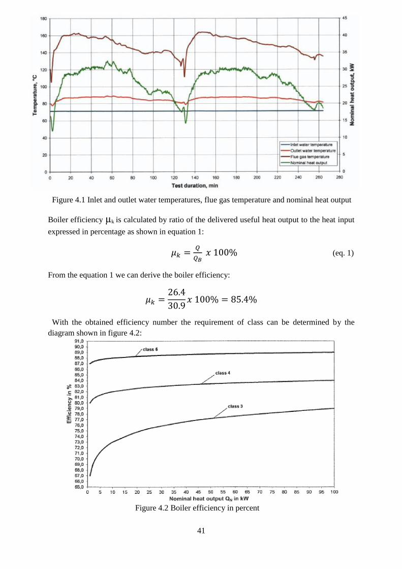
41
Figure 4.1 Inlet and outlet water temperatures, flue gas temperature and nominal heat output
Boiler efficiency µk is calculated by ratio of the delivered useful heat output to the heat input
expressed in percentage as shown in equation 1:
𝜇𝑘 =𝑄
𝑄𝐵 𝑥 100% (eq. 1)
From the equation 1 we can derive the boiler efficiency:
𝜇𝑘 =26.4
30.9𝑥 100% = 85.4%
With the obtained efficiency number the requirement of class can be determined by the
diagram shown in figure 4.2:
Figure 4.2 Boiler efficiency in percent

42
Conclusion: After applying new upgrades the efficiency of the boiler conforms to the
requirements of 4 class which is an improvement from the previous 3rd
class. The combustion
period as stated by the manufacturer at nominal heat output was 2h. During testing the heat
output specified by the manufacturer was determined within ±8%, the nominal heat output
was achieved during the combustion periods as claimed by the manufacturer. The nominal
heat output and combustion period conform to the requirements of subsections 4.4.5 and 5.8.2
of the standard EN 303-5.
Minimum heat output
The test is not applicable because the manufacturer does not declare the minimum heat output
and specifies that the boiler shall be operated with accumulator tank.
The emissions values
CO2, CO, OGC and NOx concentrations
CO2, CO, OGC and NOx concentrations were measured according to requirements of
subsections 5.2, 5.3, 5.9 and 5.10 of the standards EN 303-5 and to requirements of the
standard EN 15883
Table 4.7 CO2, CO, OGC and NOx concentrations
*value given at O2 concentration of 10%.
Diagrams of CO2, CO, OGC and NOx concentrations at nominal heat output are given in
Figures 4.3 and 4.4.

43
Figure 4.3 CO2 and CO concentrations at nominal heat output
Figure 4.4 OGC and NOx concentrations at nominal heat output
Combustion must be low-emission. The class requirements must be satisfied if the emission
values shown in the Table 4.8 are not exceeded when operating at nominal heat output or, in
the case of boilers with heat output range, when operating at nominal heat output and
minimum heat output.

44
Table 4.8: Emission limits
a Referred to dry exit flue gas, 0
oC, 1013mbar.
b Boilers of class 3 for type E-fuels in this Table and marked with classification E-fuels and e-
fuels do not need to fulfil the requirements for the dust emissions. The actual value has to be
stated in the technical documentation and shall not exceed 200 mg/m3 at 10% O2.
Conclusion: The emissions value of CO conforms to the requirements of class 3 and
emissions value of OGC conforms to the requirements of class 4 described in Table 4.8 of
emission limits of the standard EN 303-5.
Dust concentration
Dust concentration was measured according to requirements of the standards EN 303-5 and
EN 13284-1.
Dust sampling was carried out with an automatic isokinetic particulate sampling system. Dust
collection filters used in the device was filled with glass wool. Equipment used for
conditioning and weighing of the filters conforms to the requirements of the standard EN
13284-1. Samplings of the dust was carried out according to requirements of subsection 5.9.2
of the standard EN 303-5, where the arithmetic average CO2 or O2, CO, OGC (and NOx where
appropriate) contents are determined over the entire test period at nominal heat output. To

45
determine the dust content the test period is divided into at minimum 4 equal time sections.
The measurements begin in each case at the start of the sections, with the first measurement
taken when the test begins. Time per filter is limited to 30 min. The suction time per filter is ≥
30 min. The average dust content is determined from a minimum of 4 values. Sampling of
overall blank was carried out, and after sampling filters and rinsing solutions were processed
according to requirements of the standard EN 13284-1. Filters and cruets with precipitate of
rinsing solutions were dried 1 hour at 160oC temperature.
Table 4.9. Dust concentration at nominal heat output
*value given at O2 concentration of 10 %.
Expanded uncertainty of measurement of dust concentration is ±4.2%.
Conclusion: Dust concentration conforms to the requirements of the class 5 4 described in
Table 6 of emission limits of the standard EN 303-5.
4.6. Electrical consumption
Electrical consumption was measured according to the requirements of subsection 5.8.5 of the
standard EN 303-5. The average electrical power consumption during stand by shall be
measured for a minimum duration of 10 min and is stated in watts.
Table 4.9.1. Electrical consumption*
*tests were made by non-accelerated test method.
46
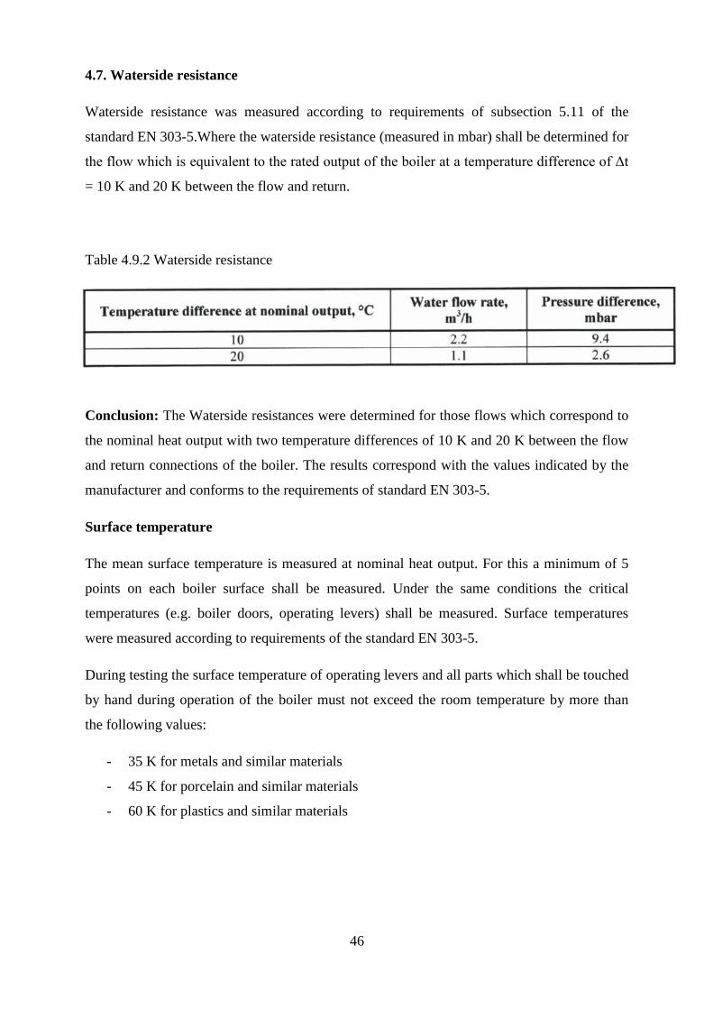
4.7. Waterside resistance
Waterside resistance was measured according to requirements of subsection 5.11 of the
standard EN 303-5.Where the waterside resistance (measured in mbar) shall be determined for
the flow which is equivalent to the rated output of the boiler at a temperature difference of Δt
= 10 K and 20 K between the flow and return.
Table 4.9.2 Waterside resistance
Conclusion: The Waterside resistances were determined for those flows which correspond to
the nominal heat output with two temperature differences of 10 K and 20 K between the flow
and return connections of the boiler. The results correspond with the values indicated by the
manufacturer and conforms to the requirements of standard EN 303-5.
Surface temperature
The mean surface temperature is measured at nominal heat output. For this a minimum of 5
points on each boiler surface shall be measured. Under the same conditions the critical
temperatures (e.g. boiler doors, operating levers) shall be measured. Surface temperatures
were measured according to requirements of the standard EN 303-5.
During testing the surface temperature of operating levers and all parts which shall be touched
by hand during operation of the boiler must not exceed the room temperature by more than
the following values:
- 35 K for metals and similar materials
- 45 K for porcelain and similar materials
- 60 K for plastics and similar materials

47
Table 4.9.3 Surfaces temperatures
Conclusion: The surface temperature of the outside of the boiler (including the bottom and
doors but except the flue gas outlet and maintenance openings of natural draft boilers) did not
exceed the room temperature by more than the allowable 60K and thus the temperatures of
boiler surfaces conform to the requirements of the standard EN 303-5.
Function check of the temperature controller and safety temperature limiter
Function check of the temperature controller and safety temperature limiter was carried out
according to requirements of standard EN 303-5. The water-side flow rate shall comply with
that specified from the nominal heat output test. The flow temperature of 75 o
C shall not be
exceeded at the start of the test.
Outlet water temperature from the boiler has reached 96.8 oC and did not exceed the
allowable temperature of 100 oC with temperature controller switched on.
After switching off the temperature controller, water temperature reached 94.8 oC, the
temperature limiting device interrupted the boiler operation (the exhauster switched off).
After 4 min. temperature reached 100.7 oC and did not exceed the allowable temperature of
110 oC. During the test CO concentration reached 1.4% and did not exceed the allowable
concentration of 5%. The boiler operation was restored manually switching on emergency
switch.
Conclusion: Functioning of the temperature controller and safety temperature limiter
conform to the requirements of the standard EN 303-5.

48
Function test on the device for dissipating excess heat
Function check of the device for dissipating excess heat was carried out according to
requirements of the standard EN 303-5. The firing is adjusted so that it corresponds to the
nominal heat output QN of the boiler, a steady state condition is reached and the outlet
pressure at the flue gas section is according to the nominal heat output. For the evaluation of
the temperatures and the CO-concentrations only mean values at a maximum average time of
one minute shall be considered.
When the boiler was operated at the nominal heat output the temperature controller was
switched off and transfer of heat to the heating system was cut off. During the test water
temperature reached 96.7 o
C and did not exceed the allowable temperature 110 o
C. During the
test CO concentration reached 0.5 % and did not exceed the allowable concentration of 5%.
Conclusion: The safety heat exchanger or other devices for dissipating excess heat does
ensure that a maximum boiler water temperature of 100oC is not exceeded. Functioning of the
device for dissipating of heat excess conforms to the requirements of the standard EN 303-5.
Loss of combustion air supply
Loss of combustion air supply test was carried out according to requirements of the standard
EN 303-5. The safety of the heating boiler shall be checked at maximum heat input under the
following conditions:
Failure of the combustion air fan;
Failure to close of the adjustable combustion air supply.
In each case only one failure shall be simulated.
The CO concentrations in the boiler shall not exceed 5 Vol. %
When the boiler was operated at the nominal heat output the exhauster was switched off.
During the test CO concentration reached 1.7% and did not exceed the allowable
concentration of 5%.
Note: Test was made by non-accredited test method.
Conclusion: Operation of the boiler during the loss of combustion air supply test conforms to
the requirements of subsection 4.3.5 of the standard EN 303-5.

49
Note: Expanded uncertainty is stated as the standard uncertainty multiplied by the coverage
factor k=2, which for a normal distribution corresponds to a coverage probability of
approximately 95%. The standard uncertainty has been evaluated in accordance with EA-
4/02.
5. Cost analysis
The cost expenses for the new boiler must be similar to that of the previous one, but at the
same time have better efficiency then its previous predecessor. The necessary in-depth cost
calculations were made for both new and old boilers and presented in the table 5.1 and table
5.2 A detailed cost analysis of both boilers is presented in the appendix section.
Table 5.1 boiler G-25E cost expenses
Boiler G-25E (old version) cost expenses
Cost elements Eur/pcs
1. Materials + packaging 512
2. Galvanic coating -
3. Transportation costs 17
4. Staff expenses 238
5. Workshop costs 753
6. Operating expenses 58
7. Factory costs 826
8. Profit 88
9. Price 915
Added value 387

50
Table 5.2 boiler B-25E cost expenses
Conclusion: The two tables show, that the cost expenses between two boilers are nearly
identical and won’t require additional funding in to its production. This means that the new
upgrades are cost effective while the boiler technical characteristics are increased.
Boiler B-25E (new version) cost expenses
Cost elements Eur/pcs
1. Materials + packaging 528
2. Galvanic coating -
3. Transportation costs 17
4. Staff expenses 238
5. Workshop costs 772
6. Operating expenses 58
7. Factory costs 830
8. Profit 96
9. Price 926
Added value 397

51
6. Conclusions
1. In this project I have introduced the main types of heating boilers, that are offered on
the market.
2. Have analyzed the current older version of the boiler, performed the necessary reverse
engineering operations and analyzed all the currently occurring issues.
3. After examining the collected data, presented new feasible upgrades in CAD models
that need to be applied to the new version of the boiler.
4. The 3D CAD version of the new B-25E boiler was created for a better understanding
on how the new upgrades will operate and to make sure that they will be simple and
practical.
5. The testing of the new boiler was performed in accordance with standards standard
LST EN 303-5:2012 (EN 303-5:2012). The test results show that the new boiler
upgrades are functional and the goal of increasing the boiler class from 3 to 4 was
achieved.
6. The cost expenses were analyzed and the results show that the new upgrades won’t
require additional funding, which means that the new upgraded B-25E boiler is cost
efficient.

52
7. Reference list
[1]Capehart, B., Turner, W. and Kennedy, W., 2006. Guide to Energy Management.
[2]ASHRAE Handbook, HVAC Systems and Equipment, 2008.
[3]Boiler and Heaters, Improving Energy Efficiency, Canadian Industry Program for Energy
Conservation, August 2001.
http://oee.nrcan.gc.ca/publications/infosource/pub/cipec/boilersheaters.PDF
[4]Federal Energy Management Program Fact Sheet, PNNL, January 2005.
http://www1.eere.energy.gov/femp/pdfs/om_combustion.pdf
[5]FEMP O&M Best Practices, a Guide to Achieving Operational Efficiency, U.S. Department of
Energy, August 2010. http://www1.eere.energy.gov/femp/pdfs/omguide_complete.pdf
[6]Efficient Boiler Operations Sourcebook, Fourth Edition, F. William Payne and Richard E.
Thompson, 1996.
[7]The Control of Boilers, 2nd Edition, Sam G. Dukelow, 1991.
[8]Heating boilers – PART 5: Heating boilers for solid fuels, hand and automatically stoked,
nominal heat output of up to 500 kW – Terminology, requirements, testing and marking.
European standard. 2012
[9] Industrial Boiler types for beginners 2010 http://www.bosch-
industrial.com/files/BR_IndustrialBoiler_Beginners_en.pdf
[10] http://en.wikipedia.org/wiki/Thermostat
[11] Fuel Quality Guide Ignition and Combustion 2005
http://www.cimac.com/cms/upload/workinggroups/WG7/
[12] How Boilers Work. F. William Payne 2008 http://www.bosch-
industrial.com/files/BR_IndustrialBoiler_Beginners_en.pdf


![HEATING CIRCUIT CONTROLLER WITH SOLID FUEL BOILER2].pdf · HEATING CIRCUIT CONTROLLER WITH SOLID FUEL BOILER ... PRELIMINARY START-UP– enables blocking the boiler return temp](https://img.dokumen.tips/doc/110x75/5b5bf7397f8b9a2d458eb2be/heating-circuit-controller-with-solid-fuel-2pdf-heating-circuit-controller.jpg)