Embed Size (px)
Citation preview
Analysis of Gas Turbine Systems forSustainable Energy Conversion
Marie Anheden
Doctoral Thesis
Department of Chemical Engineering and TechnologyEnergy Processes
Royal Institute of TechnologyStockholm, Sweden
2000
TRITA-KET R112ISSN 1104-3466
ISRN KTH/KET/R--112--SE

Contact information:Royal Institute of TechnologyDepartment of Chemical Engineering & TechnologyEnergy ProcessesS-100 44 StockholmSweden
Copyright Marie Anheden, 2000.All rights reserved.
Printed in SwedenKTH, HögskoletryckerietStockholm 2000


iii iii
Abstract
Increased energy demands and fear of global warming due to the emission ofgreenhouse gases call for development of new efficient power generation systemswith low or no carbon dioxide (CO2) emissions. In this thesis, two different gasturbine power generation systems, which are designed with these issues in mind, aretheoretically investigated and analyzed.
In the first gas turbine system, the fuel is combusted using a metal oxide as anoxidant instead of oxygen in the air. This process is known as Chemical LoopingCombustion (CLC). CLC is claimed to decrease combustion exergy destruction andincrease the power generation efficiency. Another advantage is the possibility toseparate CO2 without a costly and energy demanding gas separation process. Thesystem analysis presented includes computer-based simulations of CLC gas turbinesystems with different metal oxides as oxygen carriers and different fuels. An exergyanalysis comparing the exergy destruction of the gas turbine system with CLC andconventional combustion is also presented. The results show that it is theoreticallypossible to increase the power generation efficiency of a simple gas turbine systemby introducing CLC. A combined gas/steam turbine cycle system with CLC is,however, estimated to reach a similar efficiency as the conventional combined cyclesystem. If the benefit of easy and energy-efficient CO2 separation is accounted for, aCLC combined cycle system has a potential to be favorable compared to a combinedcycle system with CO2 separation.
In the second investigation, a solid, CO2-neutral biomass fuel is used in a small-scale externally fired gas turbine system for cogeneration of power and districtheating. Both open and closed gas turbines with different working fluids aresimulated and analyzed regarding thermodynamic performance, equipment size, andeconomics. The results show that it is possible to reach high power generationefficiency and total (power-and-heat) efficiency with the suggested system. Theeconomic analysis reveals that the cost of electricity from the EFGT plant iscompetitive with the more conventional alternatives for biomass based cogenerationin the same size range (<10 MWe).
Keywords: power generation, Chemical Looping Combustion, CO2 separation,oxygen carrier, biomass fuel, closed cycle gas turbine, externally fired gas turbine


v v
List of Appended Papers
This thesis is based on the following papers, referred to by Roman numerals I-VII.[I] Chemical-Looping Combustion - Efficient Conversion of Chemical Energy in
Fuels into Work
Anheden, M., Näsholm, A.-S., Svedberg, G.
IECEC’95, 30th Intersociety Energy Conversion Engineering Conference, Orlando, Fl,
USA, 1995, Proceedings, D.Y. Goswami et al., ed., ASME, New York, NY, Vol. 3,
pp. 75-81.
[II] Chemical-Looping Combustion in Combination with Integrated Coal GasificationAnheden, M., Svedberg, G.
IECEC’96, 31st Intersociety Energy Conversion Engineering Conference, Washington,
D.C., USA, 1996, Proceedings, W.D Jackson et al., ed., IEEE, Piscataway, NJ, Vol. 3,
pp. 2045-2050
[III] Exergy Analysis of Chemical-Looping Combustion SystemsAnheden, M., Svedberg, G.
Energy Conversion and Management, Vol. 39, No. 16-18, pp. 1967-1980, 1998, (Also
in FLOWERS’97, Florence World Energy Research Symposium, Florence, Italy,
1997, Proceedings G. Manfrida et al., ed., pp. 889-901)
[IV] Aspects on Closed Cycle Gas Turbines. Literature Report
Anheden, M., Ahlroth, M.Royal Institute of Technology, Dept. of Chemical Engineering & Technology, EnergyProcesses, 1997, TRITA-KET R73, ISSN 1104-3466, ISRN KTH/KET/EP--73--SE
[V] System Studies on a Biomass Fired CHP Closed Cycle Gas Turbine with a CFBFurnaceAnheden, M., Ahlroth, M.ECOS’98, Efficiency, Cost, Optimization, Simulation and Environmental Aspects ofEnergy Systems and Processes, Nancy, France, 1998, Proceedings A. Bejan et al., ed.,Vol. II, pp. 651-658
[VI] Externally Fired Gas Turbine Cycles for Small Scale Biomass Cogeneration
Anheden, M., Ahlroth, M., Martin, A.R., Svedberg, G.IJPG’99, International Joint Power Generation Conference, Burlingame, CA, USA,1999, Proceedings, Vol. 1, pp. 129-137
[VII] Thermodynamic Performance Analysis and Economic Evaluation of ExternallyFired Gas Turbine Cycles for Small Scale Biomass CogenerationAnheden, M., Martin, A.R.Final manuscript submitted to ASME TURBO EXPO 2000, Munich, Germany, 2000
The papers are appended at the end of the thesis.


vii vii
Contents
Abstract ...............................................................................................iii
List of Appended Papers..................................................................... v
Contents..............................................................................................vii
1 Introduction ................................................................. 1
1.1 Scope of the Work...........................................................................................2
2 Background.................................................................. 3
2.1 World Fuel Consumption and Energy Utilization...........................................32.2 The Greenhouse Effect and CO2 Mitigation....................................................32.3 Biomass Energy ..............................................................................................5
3 The Gas Turbine ......................................................... 7
3.1 Introduction.....................................................................................................73.2 The Closed Cycle Gas Turbine .......................................................................83.3 Gas Turbine Fuels .........................................................................................103.4 Environmental Performance..........................................................................11
3.4.1 CO2 Capture from Gas Turbines ............................................................11
4 Gas Turbine System with Chemical LoopingCombustion .................................................................... 13
4.1 Introduction...................................................................................................134.2 Description of Process...................................................................................144.3 CLC and Reduction of Combustion Exergy Destruction ..............................164.4 Environmental Performance of CLC - Separation of CO2 and Suppression of
NOx................................................................................................................184.5 Objectives of CLC Study ..............................................................................184.6 Studies of CLC Power Generation Systems..................................................19
4.6.1 CLC Gas Turbine System with Methane as a Fuel ................................194.6.2 CLC System with Gasified Coal as a Fuel .............................................24
viii
4.7 Discussion of Results and Conclusions ........................................................274.7.1 Identification of Critical Issues and Suggestions for Future Work ........29
5 Closed and Open Externally Fired Gas Turbines forPower Generation from Biomass Fuels .......................31
5.1 Introduction...................................................................................................315.2 Principal Description of Externally Fired Gas Turbines...............................325.3 Objectives of EFGT Study............................................................................335.4 Study of EFGT for Small-Scale Cogeneration..............................................34
5.4.1 System Configuration ............................................................................345.4.2 Thermodynamic Results ........................................................................375.4.3 Size of Equipment..................................................................................415.4.4 Economics..............................................................................................435.4.5 Comparison with Other Biomass Based Technologies ..........................45
5.5 Discussion and Conclusions .........................................................................475.5.1 Suggestions for Future Work and Identification of Critical Issues ........49
6 Concluding Remarks.................................................50
7 Acknowledgements ....................................................51
8 References...................................................................52
9 Nomenclature .............................................................57

ix ix

x

11 1
Introduction
1 Introduction
The world’s energy demand is projected to grow significantly over the next 20years. This increase will be a result of economic growth, industrial expansion, highpopulation growth, and urbanization, especially in the developing countries. Themajor part of this energy demand is believed to be met by using non-renewable fossilfuels with a limited supply. As a global community, the question we have to face is:How can we provide the energy service demanded by growing populations, yetreduce the total primary energy from non-renewable energy sources?Two technological solutions that have been suggested are:• To increase the energy conversion efficiency of existing and future energy
conversion processes by various technological advancements. This decreases thefuel consumption per unit of activity.
• Promote and further develop use of renewable energy sources like solar, windand biomass.Another important issue is the environmental impact associated with energy
conversion. Until a few years ago, the primary concern about energy impacts on theenvironment was of a local nature. The focus was on the negative consequences ofmining these fuels and the emissions of sulfur oxides (SOx), nitrogen oxides (NOx),and uncombusted hydrocarbons. Today, there is an increased awareness of thelikeliness of a global climate change associated with emissions of so-calledgreenhouse gases. The emission of carbon dioxide, CO2, from combustion of fossilfuels is now identified as a threat to the global population. The challenge that wehave to meet is:How can we decrease the CO2 emissions to the atmosphere associated withenergy conversion?Possible strategies to resolve this problem include:• Increase the energy conversion efficiency of existing and future energy
conversion processes.• Increased utilization of energy sources with lower carbon intensity, i.e. use of
fuels that emit less CO2 per unit of useful energy.• Increased utilization of CO2-neutral energy sources.• Capture and sequestration of CO2 from power plants and other sources before it
is emitted to the atmosphere.• Increased carbon sequestration by enhancing natural sinks, such as the terrestrial
biosphere and the oceans in up-take and storage of carbon.The studies presented in this thesis originate from the two questions stated
above. The overall objective is to investigate power plants that provide for a high fuelconversion efficiency. The plants studied also directly reduce the emissions of CO2
by either providing for energy efficient capture of CO2 or utilizing a CO2 neutral fuel.

2
Analysis of Gas Turbine Systems for Sustainable Energy Conversion
Another common theme is that the investigated systems involve gas turbine-basedpower generation.
1.1 Scope of the WorkThe objective of the first study, Papers I-III, is to investigate the possibilities of
decreasing the destruction of “useful energy” (also called exergy), on combustionwith a novel combustion process called Chemical Looping Combustion (CLC).Decreased exergy destruction during combustion would provide possibilities for anincreased overall efficiency of the power generation process. Chemical LoopingCombustion also makes possible easy and energy conserving separation of the CO2
formed on combustion of the fuel.In Paper I, a gas turbine system with methane as the fuel and NiO as the oxygen
carrier in the Chemical Looping Combustion system is studied from athermodynamic point of view. The calculated performance of the CLC gas turbinesystem is compared to the performance of a similar system with conventionalcombustion. This study is repeated with Fe2O3 as oxygen carrier in a MS Thesisproject under supervision of the author (Welin-Berger, 1995). In Paper II, a study ona CLC gas turbine system with gasified coal as the fuel is presented. Theperformance of the system, when using different oxygen carriers is evaluated. Thethird paper, Paper III, is focused on exergy analysis of the systems presented inPapers I and II. The works in Papers I-III are summarized in Chapter 4 in this thesis.
The second study, Papers IV-VII, explores gas turbine based cogeneration ofpower and heat from a renewable, CO2-neutral biomass fuel. The objective of thestudy is to reach both a high electric and total efficiency in a small-scale plant. Thisis to be accomplished at a competitive cost of the generated electricity. The plantsstudied contain closed and open externally fired gas turbines.
Paper IV summarizes the previous theoretical work on closed cycle gas turbines(CCGT) and operating experience from actual plants built. Paper V presents resultsfrom a thermodynamic analysis of a small-scale CCGT plant with a biomass firedcirculating fluidized bed (CFB) furnace. The variations in performance when usingdifferent working fluids - N2, He and mixture of He and CO2 - are reported. InPaper VI, the thermodynamic analysis in Paper V is complemented with aninvestigation of the dependency of working fluid selection on the equipment size. Inaddition, the study is supplemented with a comparison between open and closedcycle gas turbines. An economical analysis of the gas turbine systems in Papers Vand VI is finally introduced in Paper VII. The differences between the gas turbinecycles, both in equipment size and performance, related to the selection of workingfluid and configuration are translated into economic terms. A comparison is alsomade between the proposed gas turbine system and conventional and emergingtechnologies for small-scale biomass cogeneration. The investigations inPapers IV-VII are summarized in Chapter 5 of the thesis.

33 3
Background
2 Background
This chapter will give the reader some general background on the world’spresent fuel consumption and its projection for future use, with an emphasis on thepower generation sector. The greenhouse effect and different options to reduce CO2
emissions from the power generation industry are briefly discussed. Finally, specialimplications related to solid biomass fuel utilization are introduced.
2.1 World Fuel Consumption and Energy UtilizationDriven by increasing population and economic growth, global demand for
energy is increasing. By extending past trends of energy consumption into the future,the International Energy Agency, IEA, projects that the global primary energyconsumption is going to increase from about 110 000 TWh (or 9 400 Mtoe) in 1996to 160 000 TWh (or 13 700 Mtoe) in 2020. This implies substantial growth in energydemand and CO2 emissions. The main sources of energy today are fossil fuels likeoil, coal, and natural gas. These fuels are thought to continue to supply the major partof the world’s energy demand in the foreseeable future, with an increase in the use ofnatural gas (IEA, 1998).
In the utilization of energy, IEA projects that the demands for electricity andtransport will continue their upward trends. Fossil fuel demand for stationary services(mainly heating of buildings and processes) tend to flatten out in OECD regions butcontinues upward in China and developing countries as industrialization increasesrapidly. The energy demand for power generation follows electricity demand, but isslightly reduced as new generating plants with higher efficiency are introduced.
Regarding power generation, an increased use of natural gas is foreseen by IEA.However, coal based power plants are still expected to supply the main capacity inthe power generation sector. Electric power generation from renewable fuels isexpected to increase but is still at a low level.
These forecasts do not account for policy changes, changes in the economicgrowth rate, or the estimated resources and reserves of respective fuels as well as anynew technological breakthroughs in the power-generating sector. However, changesin these sectors over the next couple of years will have a significant impact on thefuture energy system. It is therefore important that we are aware of this fact whenmaking decisions, so that we can provide for sustainable development.
2.2 The Greenhouse Effect and CO2 MitigationHuman activity in the modern world has disturbed the composition of the
atmosphere. This has led to some of the major environmental issues of our time -ozone depletion, acid rain, and now global warming/climate change due to theenhanced greenhouse effect.

4
Analysis of Gas Turbine Systems for Sustainable Energy Conversion
Activities resulting in emission of extra amounts of greenhouse gases, especiallyCO2, N2O, CH4 and CFCs, alter the amounts of radiation trapped by the atmosphereand therefore may have an effect on climate. Measurements show that theconcentration of CO2, for instance, has increased from a pre-industrial concentrationof about 280 ppmv to 358 ppmv in 1994 (Adams et al., 1997). Recordings also showthat the average temperature on earth has increased by about 0.3° to 0.6°C since thelate 19th century - when these instrumental records began. The natural variations intemperature make it difficult to scientifically prove this temperature increase;however, in 1995 IPCC (UN’s international expert panel for climate issues)concluded that “the balance of evidence suggests a discernable human influence onthe global climate”.
If the rate of climate change can be limited, then human societies and ecosystemswill find it easier to adapt. The way to slow the rate of change is to reduce emissionsof greenhouse gases. In December 1997, climate change negotiators representing 155parties to the UN Framework Convention on Climate Change met in Kyoto, Japan.They left the conference with a protocol for subsequent signature and ratification byparties, stating reduction of 1990 or 1995 emission levels of six greenhouse gases(carbon dioxide, methane, nitrous oxide, hydrofluorocarbons, perfluorocarbons andsulphur hexafluoride) by year 2008-2012. For example, the EU commitment is toreduce the emissions by 8% and the USA by 7% (Jefferson, 1998).
Of all the greenhouse gases, CO2 contributes the most (about 55%) to theincreased greenhouse effect, if both the concentration and how much the gascontributes to the greenhouse effect are taken into account. One of the largest sourcesof CO2 emissions is power generation using fossil fuels. In the EU and the UnitedStates, the power generation sector contributes with approximately 1/3 of the totalCO2 emissions. In Sweden, the contribution from the power generation sector islower (about 18%) since the dominating part of electricity is generated in nuclearpower plants or hydro power plants almost without any CO2 emissions. A contrastbetween CO2 emissions in Sweden and the USA, based on the source, is shown inFigure 2.1.
In the future, the share of global CO2 emission from the power industry sectormay increase due to the industrialization of the developing countries and continuedelectrification of the industrial and building sectors in the developed countries.
Sweden
Manufact., Construction
Industry26%
Transport37%
Other sectors
19%
Other 0%
Energy Industry
18%
Figure 2.1 CO2 Emissions from fuel combustion by sectors in Sweden (total52.7 Mtonnes CO2) and USA (total 5 375 Mtonnes CO2), year 1997
(UNFCCC, 1999).
USA
Transport30%
Manufact., Construction
Industry21%
Energy Industry
37%
Other 1%
Other sectors
11%
55 5
Background
On a longer-term perspective, even the transportation sector may be electrified.Therefore, ways of reducing CO2 emissions from power plants are now beinginvestigated.
There are a variety of options available for reducing greenhouse gas emissions.In most cases, the least expensive options involve reducing emissions at the source –for example, improving the efficiency of using fossil fuels. The fuel utilization canalso be increased through cogeneration of heat and power. Substitution, e.g.,replacing a high carbon fuel with a low carbon fuel, can achieve useful reductions atrelatively low cost, where supplies are available. However, to make deep reductionsin emissions typically requires more extended measures such as changing from fossilfuels to renewable sources, for instance utilization of biomass fuels. Enhancement ofthe natural sinks of carbon, such as the oceans and forests, has also been discussed.
Only in the past few years has serious considerations been given to technologieswhich would allow deep reductions in greenhouse gas emissions while continuing touse fossil fuels, the so-called carbon sequestration option. Carbon sequestration canbe defined as the capture and secure storage of carbon that would otherwise beemitted to or remain in the atmosphere. The idea is to keep carbon emissionsproduced by human activities from reaching the atmosphere by capturing anddiverting them to secure storage, or to remove carbon from the atmosphere byvarious means and store it. Carbon sequestration should be seen as a complement tothe strategy of improving efficiency and increasing the use of non-fossil fuels. Inparticular, the option of capturing the CO2 emitted at the power plant on combustionis seen as technically feasible and could be implemented relatively quickly. Thecaptured CO2 would then be disposed in the deep ocean and geological formationslike deep aquifers, exhausted gas and oil reservoirs, and unmineable coal seams.Atmospheric carbon can also be captured and sequestered by enhancing the ability ofterrestrial or ocean ecosystems to absorb it naturally and store it in a stable form.These options are considered to be able to store the anthropogenic CO2 emissionsover a vast amount of time (Herzog and Vukmirovic, 1999).
However, the option of CO2 capture and storage provide a number of challengesthat must be addressed. One challenge is to reduce the cost and efficiency penaltyassociated with capture. Various options for CO2 separation from power plants arepresently being investigated. Another challenge is to verify the feasibility of CO2
storage in various geological and ocean reservoirs. This includes understanding ofthe long term fate of the CO2 and addressing environmental and safety concerns.
2.3 Biomass EnergyRenewable energy is any energy source that can be either replenished
continuously or within a moderate timeframe. These energy supplies can be endlessresources such as the sun, the wind, and the heat of the earth, or they can bereplaceable such as plants. In contrast, fossil fuels like oil, coal, and natural gas formso slowly in comparison to our rate of energy use that they are considered finite orlimited resources.
Renewable power generation sources include solar power, biomass power, windpower, hydropower, and geothermal power. Biomass power is one of the most

6
Analysis of Gas Turbine Systems for Sustainable Energy Conversion
favorable sources in this category for a number of reasons. With proper harvestingpractices, biomass is a sustainable resource that can be found in most regions of theworld. The combustion of biomass produces nearly zero net CO2 emissions and, withclean combustion techniques, emits low levels of unburned hydrocarbons, NOx, andSO2. Figure 2.2 illustrates the biomass fuel utilization cycle.
Fuels included in the biomass category are mainly wood (logs, bark, sawdust,and energy plantations), straw, energy grasses, and digester liquors from pulp mills.Sometimes refuse and peat are included in this category. In the industrializedcountries, biomass fuels are used in four main areas - the forest product industry,district heating plants, the residential sector, and electricity production - while indeveloping countries, biomass is mostly used for cooking and heating.
The use of biomass energy for power generation has increased over the lastdecade. Most biomass power plants operating today are using a steam boiler andsteam turbine. The majority of plants is used for combined heat and powergeneration. Grate firing is dominating but development of the fluidized bedcombustion technology has made it possible to increase the utilization of variousbiomass and waste products in both power and heat generation.
A number of different new technologies are presently being developed forbiomass based power generation to increase the power conversion efficiency. Themain R&D challenges connected to biomass based power production includeresolving issues around ash chemistry, NOx reduction, improving materials, anddeveloping sufficient energy crops for feedstocks. Long term demonstrations ofadvanced technology concepts are also necessary.
heat
electricity
residues
chips
ashes
carbon dioxide
Figure 2.2 Biomass based power generation and the carbon and mineralcycle (from Yan et al., 1997).
77 7
The Gas Turbine
3 The Gas Turbine
Gas turbines are selected as the prime mover for power generation in bothstudies in this thesis. The main reason for this selection is that gas turbines are able tooperate at a high efficiency when utilizing a high temperature heat source. The focusin this chapter is on special gas turbine related issues important to the studies inChapter 4 and 5, e.g. the special characteristics of closed cycle gas turbines, thetechnologies available for using solid fuels, and the approaches for separating CO2.
3.1 IntroductionA simple gas turbine is comprised of three main sections: a compressor, a
combustor and a turbine. The gas turbine operates on the principle of the Braytoncycle where compressed air is mixed with fuel and burned under constant pressureconditions. The resulting hot gas is expanded through a turbine to perform work.
The simple cycle gas turbine power plants designed to be suitable for electricutility applications have the advantage of high power output for a relatively smallsize and weight, low initial cost, rapid installation, short start-up times, fuelflexibility, and zero water consumption for cooling. A typical gas turbine for electricutility applications has a power output range between 50 kW and 240 MW.
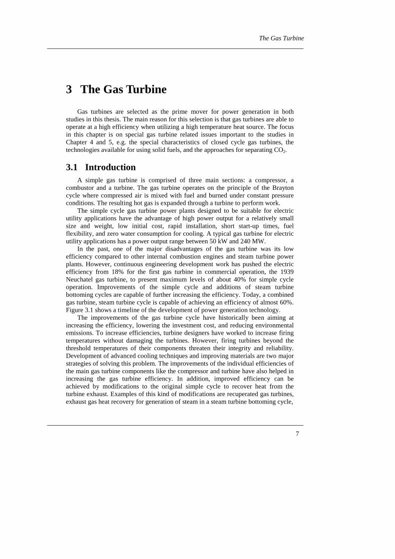
In the past, one of the major disadvantages of the gas turbine was its lowefficiency compared to other internal combustion engines and steam turbine powerplants. However, continuous engineering development work has pushed the electricefficiency from 18% for the first gas turbine in commercial operation, the 1939Neuchatel gas turbine, to present maximum levels of about 40% for simple cycleoperation. Improvements of the simple cycle and additions of steam turbinebottoming cycles are capable of further increasing the efficiency. Today, a combinedgas turbine, steam turbine cycle is capable of achieving an efficiency of almost 60%.Figure 3.1 shows a timeline of the development of power generation technology.
The improvements of the gas turbine cycle have historically been aiming atincreasing the efficiency, lowering the investment cost, and reducing environmentalemissions. To increase efficiencies, turbine designers have worked to increase firingtemperatures without damaging the turbines. However, firing turbines beyond thethreshold temperatures of their components threaten their integrity and reliability.Development of advanced cooling techniques and improving materials are two majorstrategies of solving this problem. The improvements of the individual efficiencies ofthe main gas turbine components like the compressor and turbine have also helped inincreasing the gas turbine efficiency. In addition, improved efficiency can beachieved by modifications to the original simple cycle to recover heat from theturbine exhaust. Examples of this kind of modifications are recuperated gas turbines,exhaust gas heat recovery for generation of steam in a steam turbine bottoming cycle,

8
Analysis of Gas Turbine Systems for Sustainable Energy Conversion
Figure 3.1 Gas and steam turbine efficiency evolution, McDonald (1994).
the STIG cycle, the HAT cycle, and the chemically recuperated cycle. Descriptionsof these advanced configurations can, for instance, be found in Korobitsyn (1998).
3.2 The Closed Cycle Gas TurbineThe gas turbine working fluid circuit can be arranged in two ways: either with an
open circuit or a closed circuit. In the closed cycle gas turbine, the gas turbineexhaust is recycled to the compressor after being cooled and thereby forms a closedworking fluid circuit, while in the open cycle the turbine exhaust is released to theenvironment, as shown in Figure 3.2. In addition, the heat is supplied to the closedcycle through a heat exchanger, instead of direct combustion of the fuel in theworking fluid circuit as in the open cycle. The open cycle configuration is the mostcommon configuration. Worldwide, only about 20 closed cycle gas turbines havebeen built. The perhaps most well-known closed cycle gas turbine plant is theOberhausen II plant built in the former Federal Republic of Germany. This plant wascommissioned in 1974 and used helium as working fluid.
Fuel
Air
Heat supplied by heat source
Heat rejected to heat sink
Figure 3.2 Simple open cycle gas turbine and closed cycle gas turbine.

99 9
The Gas Turbine
The advantages of the closed cycle gas turbine have been exemplified manytimes in literature, see for example McDonald (1985). The following is a summary ofthe most important advantages:• wide range of applicationsThe closed cycle gas turbine is potentially applicable to a wide range of areasincluding electric power generation, marine propulsion, space power systems,underwater propulsion systems, and in terrestrial transportation systems such asbuses and rail units.• adaptability to a wide range of heat source optionsThe closed cycle gas turbine is capable of handling a wide range of heat sourceoptions. This includes dirty combustible fuels like coal, peat, wood, biomass, refuseetc. and also clean fossil fuels like oil and natural gas. Stored thermal energy and heatfrom chemical reactions and solar energy can also be utilized. Nuclear heat sourceslike fission reactors and radioisotopes have also been investigated. Future use offusion reactors also represents a potential heat source.• no need for pressurized fuelSince there is no direct contact between fuel and the turbine working fluid, there isno need of pressurizing the fuel. This saves on compression work in the case of usinga gaseous fuel. It also simplifies systems with solid fuels, since the complication offeeding a solid into a pressurized system is avoided.• operational fuel flexibilityThe closed cycle gas turbine is adaptable to a quick change of heat source if the fuelsupply changes. It is also less sensitive to changes in the fuel quality.• freedom in working fluid selectionThe closed cycle gas turbine uses the same working fluid repeatedly and gases otherthan air can be used when their thermodynamic and transport properties areadvantageous. Gases such as nitrogen, carbon dioxide, helium, argon, krypton, xenonand various gas mixtures have been suggested as suitable working fluids.• cleanliness of working fluidSince the working fluid is contained in a closed system, it can be kept free ofmoisture and contaminants including those arising from the combustion process.Theoretically, all dangers of fouling or eroding the blades of the compressors orturbines are eliminated. The possibilities of depositions on heat exchanger surfacesare likewise eliminated. Therefore, long life and unattended operation can beexpected.• possibility of pressurization of the whole systemWith a closed cycle gas turbine, it is possible to pressurize the whole system. In thisway, the required flow area within turbomachinery, ducts and heat exchangers can beminimized. Reduced equipment size can give lower capital cost and also give a lowerweight and size to the system. High pressure also improves the heat transfercharacteristic of the working fluid.• part-load operation with high efficiencyWith a pressurized closed system, it is possible to change the power output bychanging the pressure level instead of reducing the turbine inlet temperature as in anopen cycle gas turbine. The volume flow through the machine remains the same

10
Analysis of Gas Turbine Systems for Sustainable Energy Conversion
while the mass flow changes and this, in combination with a constant turbine inlettemperature, yields a good aerodynamic efficiency over a wide power range.• containment of working fluidIn certain applications, a continuous rejection of the gas turbine working fluid to theatmosphere is undesirable for safety or environmental reasons. This is the case whenthe working fluid represents the primary cooling medium in a nuclear reactor andtherefore may have been contaminated with radioactive material. Containment of theworking fluid also enables the gas turbine to operation in environments where normalair-breathing machines can not be used due to the lack of gaseous atmosphere, like inspace and in under water applications.
Of course, these advantages of the closed cycle gas turbine system do not comewithout some offsetting costs. Selecting a closed cycle gas turbine for any particularapplication must be proven cost effective considering the following offsetting costs:• heat source system including cycle high temperature heat exchanger• components made structurally suitable for high system pressures and
temperatures• cycle heat rejection heat exchanger and system• working fluid gas management systemAnother disadvantage is the lower maximum allowable heat addition temperature ofa closed cycle gas turbine compared to an open cycle gas turbine. The lowermaximum temperature is a result of temperature limitations on the heat source heatexchanger. This limits the maximum power conversion efficiency of the closed cyclegas turbine.
3.3 Gas Turbine FuelsToday the principal fuels burned in industrial gas turbines are natural gas,
petroleum distillates, residual fuel oil, propane, blast furnace gas, and butane. Effortsto enable gas turbines to operate on solid fuels like coal and biomass are presentlybeing undertaken. Other potential fuels to be used in gas turbines include methanol,hydrogen, and vegetable oil.
The development of coal and biomass gasification systems to produce a cleangas that can be directly combusted in a gas turbine combustor is an option beingconsidered. This technology is applied in Integrated Gasification Combined Cycle(IGCC) systems. Gasification is also considered as an option for gas turbine basedpower generation from bagass, an organic waste product from sugar manufacturing,or black liquor, a mixture of spent cooking chemicals and organic substances fromthe chemical pulp cooking process.
Another alternative for integrating solid fuel combustion in the gas turbinesystem is pressurized fluidized bed combustion, PFBC. Here, the gas turbinecompressor supplies compressed air to a fluidized bed combustor. The hotcombustion products are expanded in a turbine and the exhaust heat is recovered in asteam turbine bottoming cycle. The PFBC technology is mainly considered to besuitable for coal.
A third alternative is using an externally (or indirectly) fired gas turbine. In anexternally fired gas turbine, combustion products never directly contact the gas

1111 11
The Gas Turbine
turbine. Rather, the combustion products transfer heat through a high temperatureheat exchanger to a working fluid, such as air, that drives the turbine. In this way thefuel cleaning requirements can be lessened.
The efficiency of all the above mentioned technologies with a gas turbine steamturbine combined cycle is estimated to reach 40% (LHV) with today’s technology.Future projections show a potential of reaching an efficiency just exceeding 50%,(Hazard, 1985). Power generation using both closed and open externally fired gasturbines is the main topic in Chapter 5 of the thesis.
3.4 Environmental PerformanceUpon comparison, gas turbines have very low pollutant emissions, particularly
when operating with natural gas. Their high efficiencies especially when operating incombined cycle or in cogeneration mode make the emissions per unit of generateduseable energy low. Implementing modifications to the combustion process cansignificantly reduce most of the air pollutants, such as NOx, CO and organicsubstances. Substantial efforts have been made to develop different emissionreduction techniques, especially to develop low NOx gas turbines. Gasification ofsolid fuels provides for ways of removing pollutants like sulfur from the fuel gasbefore it is combusted. In pressurized fluidized bed combustion, a sorbent such aslimestone or dolomite is used to capture sulfur released by the combustion. Theexternally fired gas turbine systems can be integrated with combustion systems thathave low emissions, like atmospheric fluidized bed combustion systems.
The ways of eliminating CO2 emissions from gas turbines is a new area ofresearch. Here the studies have focused on two approaches: either enabling the gasturbine to operate on a CO2-neutral fuel like biomass, or using a fossil fuel and thencapturing the CO2 formed instead of venting it into the atmosphere.
3.4.1 CO2 Capture from Gas Turbines
The goal of CO2 separation and capture is to isolate CO2 in concentrated formthat enables efficient transport and storage. The carbon contained in the fuel caneither be separated from the flue gas in a post-combustion approach or before theactual combustion process in a pre-combustion approach.
The post-combustion approach is suitable for old power plants since no changesare required for the power generation process. However, an alternate, more advancedpost-combustion approach has been suggested, which increases the concentration ofCO2 in the flue gas through the use of oxygen for the combustion instead of using air.To maintain thermal conditions in the combustion zone and prevent overheating ofthe combustor liner materials, some of the flue gas would be recycled to the furnace,giving this approach the name “CO2 recycle technology”. Since the key to separatingCO2 from flue gas is to remove the CO2 from the nitrogen, eliminating the airremoves the primary source of nitrogen, which greatly simplifies the flue gas clean-up. However, an expense now arises from the production of the oxygen.
In pre-combustion separation, the hydrocarbon fuel is chemically shifted toobtain a fuel gas rich in H2 and with the carbon in the form of CO2. This reduces the

12
Analysis of Gas Turbine Systems for Sustainable Energy Conversion
size of the flow to be treated in the capture stage and increases the CO2 concentrationcompared to the post-combustion approach.
The CO2 in the exhaust or fuel stream has to be removed from the other streamconstituents in the next stage of the process. With conventional methods, CO2 can beabsorbed from gas streams by contact with amine-based solvents or cold methanol. Itcan also be removed by adsorption on activated carbon or other materials or bypassing the gas stream through special membranes. The pressure, temperature, otherconstituents present, concentration of CO2 and the total volume to be treateddetermines which technology is best suited (IEA, 1993), (DOE, 1999). Several ofthese methods are commercially available. However, they have not yet been appliedat the scale required for use as part of a CO2 emissions mitigation strategy.
Historically, CO2 capture processes have required significant amounts of energy,which reduces the power plant’s net power output and increases the cost ofelectricity. Table 3.1 shows typical penalties associated with CO2 capture both as thetechnology exists today and how it is expected to evolve in the next 10-20 years,together with the estimated cost of electricity. Both the conventional coal and naturalgas case use similar capture technologies, but because natural gas is less carbonintensive than coal, it has a lower energy penalty (Herzog et al., 1997).
To reduce the energy requirements and bring the cost of CO2 capture toacceptable levels will most likely require a combination of the following:• Increased base power plant efficiencies.• Reduced capture process energy needs.• Improved integration of the capture process with the power plant.One novel method that combines all these requirements is Chemical LoopingCombustion, CLC. It has been identified by US DOE as a method that could have asignificant potential for combining power generation with fossil fuels and CO2
separation (DOE, 1999). Chemical Looping Combustion is described in further detailin the following chapter.
Table 3.1 Typical energy penalties due to CO2 capture using conventionaltechniques, and estimated cost of electricity (COE) (Herzog et al., 1997,Herzog and Vukmirovic, 1999). The energy penalty is defined as percent
reduction in power output compared to the same plant without CO2 capture.Energy PenaltyPower plant type
Today FutureCOE
($/MWhe)Incremental
COE ($/MWhe)Conventional Coal,(Pulverized coal)
27-37% 15% 70-80 23-31
Natural Gas,NGCC
15-24% 10-11% 50-60 19-21
Advanced Coal,IGCC
13-17% 9% 60-70 11-17

1313 13
Gas Turbine System with Chemical Looping Combustion
4 Gas Turbine System with ChemicalLooping Combustion
4.1 IntroductionIn 1983, Horst Richter and Karl Friedrich Knoche introduced a new combustion
process where the fuel is oxidized by an oxygen carrier, i.e. an oxygen-containingcompound (Richter and Knoche, 1983). This combustion process was later given thename Chemical Looping Combustion (CLC). The main objective of introducing CLCat that time was to increase the energy conversion efficiency of thermal power plantsby decreasing the combustion exergy loss. However, lately this process has gainedattention as being a promising way of integrating combustion and CO2 separation inpower plants.
The research on CLC described in this thesis has been focused on systemsimulations of gas turbine based power generation with Chemical LoopingCombustion. The main interest has been to study the exergy losses in the combustionsystem, while the CO2 separation has been of secondary interest. Similar studies havebeen performed at Dartmouth College, USA (Harvey and Richter, 1994, Harvey,1994), the Tokyo Institute of Technology, Japan (Ishida et al., 1987, 1997, Ishida andJin, 1994a, Jin and Ishida, 1997). Bisio et al. (1998) repeated the calculationspresented by Ishida and Jin (1994a). Results in the form of electric efficiency (ηe, netelectric power generated per fuel input) from these system simulations aresummarized in Table 4.1. In 1995, Tokyo Electric Power Co., Inc. patented aChemical Looping Combustion gas turbine system (US Pat. 5,447,024).
Table 4.1 Results from CLC power generation system simulations.OxygenCarrier
Fuel System ηe
(% LHV)Reference
Fe2O3/FeO CH4 Fuel reformingGT (1100°C)
50% Ishida et al, 1987
NiO/Ni CH4 Humid airGT (1200°C/1100°C)
55% Ishida and Jin, 1994a
Fe2O3/Fe3O4 CH4 Fuel reformingFuel cell
GT (1180°C)
69% Harvey and Richter, 1994
NiO/Ni Coal Coal gasificationHumid air
GT (1200°C)
51% Jin and Ishida, 1997
NiO/Ni H2 Humid airGT (1350°C)
67% Ishida et al., 1997

14
Analysis of Gas Turbine Systems for Sustainable Energy Conversion
Development of oxygen carriers and reactor systems has been performed at theTokyo Institute of Technology (Ishida and Jin, 1994b, 1997, Ishida et al., 1996, 1998,1999, Jin et al., 1998, 1999) and the National Institute for Resources andEnvironment (NIRE), Japan, (Hatanaka et al., 1997). In 1998 TDA Inc., USA, wasawarded a research contract under US DOE’s program for novel carbon sequestrationtechniques to investigate the potential of their “Sorbent Energy Transfer System,SETS” which seems identical to a Chemical Looping Combustion system with acombined cycle power generation system. The project is presently focusing ondeveloping an oxygen carrier and a reactor system. Chalmers University ofTechnology, Sweden together with the Royal Institute of Technology has also beenawarded research contracts to develop oxygen carriers and reactors and to performsystem simulations. The Swedish projects are financed by the Environmental Sectionat Chalmers University of Technology and the University of Gothenburg, by theSwedish National Energy Administration under the program “Thermal Processes forElectricity Production”, and by Ångpanneföreningen (ÅF).
4.2 Description of ProcessThe fundamental differences between conventional combustion and ChemicalLooping Combustion are demonstrated in this chapter. Two simple schematics ofpower generating systems with conventional combustion and Chemical LoopingCombustion are given in Figures 4.1a and b.
In the conventional combustion process, the hydrocarbon fuel CaHb and air enterthe combustor. The fuel reacts with the oxygen, O2, in the air and is oxidized tocarbon dioxide, CO2, and water, H2O, according to reaction (4.1) below, with avisible flame.
C222ba H + OH 2
b + CO a O
4
ba HC ∆→
++ (4.1)
This reaction is exothermic, i.e. heat equal to ∆HC is released. The heated excess airand combustion products leave the combustor.
In Chemical Looping Combustion, the overall combustion reaction takes place intwo reaction steps in two separate reactors as shown in Figure 4.1b. In the so-calledreduction reactor (Red), the fuel is oxidized by the oxygen carrier, i.e. the metaloxide MeO.
a b
OxAir
C Ha b
2CO
2HO
ExcessAir
Condenser
MeMeO
Controlvolume
Red
Air
C Ha b
ExcessAir
2CO
2HO
Combustor
PowerGenerationSystem
PowerGenerationSystem
PowerGenerationSystem
Figure 4.1 a) System with conventional combustion.b) System with Chemical Looping Combustion.

1515 15
Gas Turbine System with Chemical Looping Combustion
The metal oxide is reduced to a metal or a metal oxide with a lower oxidationnumber, Me, in the reaction with the fuel, reaction (4.2). To regenerate the oxygencarrier, it is transported to the second reactor, the oxidation reactor (Ox), where it isreoxidized by oxygen in the air according to reaction (4.3). Both reactions proceedwithout a visible flame.
The net reaction over the two Chemical Looping Combustion reactors isequivalent to the conventional combustion reaction. This is verified by addingreaction (4.2) and (4.3) and observing that the sum is the conventional combustionreaction.
Me 2
b + 2a+OH
2
b+CO aH+MeO
2
b + 2a+HC 22redba
→∆
(4.2)
ox2 H+MeO 2
b2aO
4
b+a+Me
2
b2a ∆
+→
+ (4.3)
C222ba H + OH 2
b + CO a O
4
ba HC ∆→
++ (4.4)
To confirm this conclusion, a control volume is drawn to enclose the two ChemicalLooping Combustion reactors. It can then be seen that the same material is enteringthe CLC system, i.e. fuel and air and exiting, i.e. excess air and combustion products,as in the conventional combustor. The metal/metal oxide is circulated between thetwo CLC reactors and never leaves the system.
Chemical Looping Combustion is best suited for gaseous fuels like methanesince the reaction rate has to be sufficiently high to allow the process equipment incontinuous operation to be reasonable sized. Solid fuels like coal can be used if theyare first gasified and then oxidized in the Chemical Looping Combustion system. Thesame procedure can be used for liquid fuels.
Metal oxides with metals from families VIIA and VIIIA of the periodic table,such as NiO, Fe2O3 and Mn3O4, were initially suggested to be suitable as oxygencarriers from a thermodynamic point of view (Richter and Knoche, 1983, Harvey,1991). The experimental work today is focused on using NiO or other Ni-based metaloxides (Tokyo Institute of Technology), different iron oxides (Chalmers), and iron-and copper-based oxides (TDA Inc.). The oxygen carrier is thought to be supplied tothe system in the form of particles. The addition of inert materials to the particles isanother area of research. Adding YSZ (Yttria Stabilized Zirconia), TiO2 or Al2O3 hasbeen suggested by Ishida et al. (1998). The inert material plays the role of an oxideion conductor to enhance the ion permeability in the solid. It also increases theparticle’s porosity. Increased porosity increases the diffusion rate of reactants andproducts to and from the interior of the particle, which in turn leads to an increasedoverall reaction rate. The inert materials also improve the physical strength of theparticles and prevent undesirable fragmentation.
Attempts have been made to suggest a suitable design for the oxidation andreduction reactors. Harvey and Richter (1994) suggest using two isothermal fluidizedbed reactors with alternating valves. This allows the operation of a reactor to beswitched from oxidation to reduction and vise versa without transporting the solids toanother reactor. The oxidation reaction is run under atmospheric conditions while the
+

16
Analysis of Gas Turbine Systems for Sustainable Energy Conversion
Air
Fuel
Excess air
CO2+H2OOxidationreactor Reduction
reactor
Figure 4.2 CLC reactor system suggested by Mattisson and Lyngfelt(1999).
reduction reaction is pressurized. Notable is also that the heat requirements of thetwo reactors are exactly matched. Grönkvist (1995) tried to design and size thereactors for the system described in Paper I. Grönkvist found that the best type ofreactor for the oxidation reaction is a fluidized bed reactor. For the endothermicreaction in the reduction reactor, a counter-current moving bed is considered the bestchoice since it is possible to achieve a high conversion of both phases in such areactor. Mattisson and Lyngfelt (1999) suggest using a circulating fluidized bedreactor with an external fluidized bed reactor connected to the return leg, Figure 4.2.A high gas velocity that entrains the solid particles is used in the oxidation reactor.The gas and the solids are separated in a cyclone and the particles fall down throughthe return leg to the reduction reactor, a bubbling fluidized bed. Particle locks keepthe gas streams from flowing from one reactor to the other.
4.3 CLC and Reduction of Combustion ExergyDestruction
Chemical Looping Combustion is one of several methods that are claimed toreduce combustion exergy losses. Exergy, also known as availability, is a measure ofthe maximum useful work that can be obtained when a system is brought to a state ofequilibrium with the environment in a reversible process. Due to the irreversibility ofthermal processes, the work obtained is always less than the maximum work. Hence,by analyzing the exergy flows within a system, imperfections can be pinpointed andquantified. Also, different sorts of energy can be directly compared in exegetic terms.For more detailed information about exergy analysis, see for instance Moran (1989)or Szargut et al. (1988).
The major loss of exergy in conventional thermal power plants occurs in thecombustion process. Up to as much as 20-30% of the exergy content of the fuel canbe destroyed. The high level chemical energy bound in the fuel is downgraded to lowlevel thermal energy in the highly unordered and irreversible reaction between the

1717 17
Gas Turbine System with Chemical Looping Combustion
fuel and oxygen in the combustor. This energy degradation decreases the totalefficiency whereby the fuel energy is finally converted to electricity in a thermalpower plant (Dunbar and Lior, 1991). The exergy efficiency of the conventionalcombustion process increases with a decrease in excess air or an increase in airpreheater temperature and pressure. The efficiency is also affected by the molecularstructure of the fuel. The combustion exergy efficiency decreases with hydrocarbonchain length and increases with an increase in unsaturated bonds (Steward et al.,1998).
Beretta et al. (1992), suggested that preheating fuel and air at a certain pressureto a temperature corresponding to the temperature where the mixture exists inequilibrium, and then starting the reaction by cooling the mixture, wouldtheoretically result in a reversible combustion. The exergy content of the fuel wouldthen not be destroyed. However, for standard hydrocarbons, this reaction schemewould require extreme preheating or an extreme dilution of the hydrocarbon fuel. Forthe method to be practical, a suitable reaction scheme needs to be identified thatallows for a lower equilibrium temperature which is suitable for current technologymaterials without having the fuel highly diluted.
Using fuel cells to convert the chemical energy directly into electricity is anotherway of improving the fuel energy utilization for simple fuels like hydrogen, H2, andcarbon monoxide, CO. In a fuel cell, oxidation of the fuel by direct reaction betweenfuel and air is prevented. The energy released is directly converted into an electriccurrent, thus avoiding generation of large amounts of thermal energy. Fuel cells stillsuffer from some technical and economic drawbacks that have hindered a widercommercial application. Considerable resources are presently invested worldwide tofurther improve and develop fuel cells.
CLC has attracted interest as a method to decrease combustion exergy losses.This depends on the reaction path and thermodynamics of the two-step CLC reaction.The reactions are performed in a more ordered way than the conventionalcombustion reaction since direct contact between fuel and the combustion air isprevented. Instead the overall reaction takes place in two solid/gas phase reactions.The reaction between the fuel and the oxygen carrier MeO is usually endothermic,i.e. heat equal to ∆Hred is consumed. The reaction takes place at a medium-lowtemperature with recovery of heat at a medium temperature level. This heat can betaken from the exhaust of a gas turbine, for instance. The reoxidation of the oxygencarrier is exothermic, i.e. heat equal to ∆Hox is released. According to Hess law or asimple energy balance, the sum of heat of reaction for reaction (4.2) and (4.3) isequal to the heat of combustion, ∆HC. This means that the oxidation reaction,reaction (4.3), must have a higher heat of reaction than the conventional combustionreaction. As a result, more heat is released at a high temperature through recovery ofthermal energy at a low temperature, compared to conventional combustion. TheChemical Looping Combustion system is thereby acting as a chemical heat pumpsystem in upgrading the low-level energy to high-level energy. Therefore, theirreversible exergy destruction is thought to be less than in conventional combustionof the fuel, i.e. the exergy content of the released fuel energy should be betterpreserved. When this exergy is utilized efficiently in the subsequent powergeneration system, the overall thermal efficiency can be increased.

18
Analysis of Gas Turbine Systems for Sustainable Energy Conversion
4.4 Environmental Performance of CLC - Separation ofCO2 and Suppression of NOx
One significant advantage in Chemical Looping Combustion is that thecombustion products CO2 and H2O leave the reduction reactor as a separate streamundiluted by excess air, Figure 4.1b. In this way it is easy to separate the greenhousegas CO2 to be stored or utilized in an environmentally safe way. All that is needed toget an almost pure CO2 product is to condense the water vapor and remove the liquidwater as shown in Figure 4.1b. This is to be compared to the costly and energy-demanding separation processes that are required for separating CO2 from the mixedexhaust from the conventional combustor, as described in Chapter 3.4.1.
In addition, in the CLC combustion process, the fuel and air go through differentreactors with no flame, which provide an opportunity to thoroughly suppress thegeneration of NOx (Ishida and Jin, 1996).
4.5 Objectives of CLC StudyThe main objectives of the CLC study presented in Papers I-III have been the
following:
• Model a gas turbine, (GT), based power generating system with CLC that can beconstructed using existing conventional equipment to as large extent as possible.The CLC oxidation reaction temperature should be adapted to temperatures usedin conventional gas turbines. The main objective of the system is to generatepower at high efficiency.
• Investigate the possibilities of using the CLC GT system with different fuels.• Compare CLC GT system with different metal oxides as oxygen carriers.• Compare the performance of the CLC GT system with the performance of a
similar GT system with conventional combustion.• Perform an exergy analysis of the proposed CLC GT system and locate the
points of exergy destruction. The CLC reactions are of particular interest. Theresults from the CLC GT system exergy analysis are to be compared with theresults from an exergy analysis of the GT system with conventional combustion.
• Identify critical components and processes in the CLC system.
Aspen Plus, a program commonly used by engineers in the process and energyindustries, has been used for the simulations. The program contains an array ofpredefined components, along with an extensive database of thermophysicalproperties. With the different system components and connectivity specified, energyand mass balances are computed sequentially until convergence is attained. Theexergy of each stream is then computed using thermodynamic data from the AspenPlus stream result-file.

1919 19
Gas Turbine System with Chemical Looping Combustion
4.6 Studies of CLC Power Generation Systems
4.6.1 CLC Gas Turbine System with Methane as a Fuel
The purpose of the investigation presented in Paper I and continued by Welin-Berger (1995) is to determine if it is possible to reach a high electric efficiency with aless complex CLC gas turbine configuration than the systems presented by Ishida etal., 1987 and Ishida and Jin, 1994a. Methane, CH4 (the main component of naturalgas) is used as a fuel and NiO or Fe2O3 is used as oxygen carrier. The performance ofthe CLC systems is compared to a gas turbine system with conventional combustionof the fuel. The detailed exergy analysis in Paper III reveals whether or not thecombustion exergy loss is decreased by introducing Chemical Looping Combustioninto the system as a replacement for conventional combustion.
4.6.1.1 System DescriptionThe system introduced in Paper I is a Chemical Looping Combustion gas turbine
system with reheat. Reheat denotes that the system has two combustors, one at thehigh pressure where the first combustion takes place with full combustion of the fueland then a second combustor at an intermediate pressure where additional fuel issupplied and fully combusted. Design data used for the gas turbine system is takenfrom a state-of-the-art gas turbine, in this case the ABB’s gas turbines GT24/26.Following the specifications for GT24/26, the maximum turbine inlet temperature isset to 1235°C and the maximum pressure is set to 30 bars for GT system 1 with air asthe working fluid. Turbines for expanding the gases from the reduction reactors areadded to increase the power production.
Nickel oxide, NiO, is used as an oxygen carrier in the study in Paper I,Figure 4.3. The NiO particles are reduced to Ni by the fuel. The reactors arepressurized to allow a direct connection with the gas turbine system.
Air
Ni
Methane Methane
NiO
Exhaust 2Exhaust 1Exhaust 1
Red A
GT1AGT1B
GT2A GT2BExhaust 1-Excess air
Exhaust 2-carbon dioxide+water
Ox B
Red B
Ox A
Hx A Hx B
Figure 4.3 CLC gas turbine system with NiO as oxygen carrier andmethane as a fuel.

20
Analysis of Gas Turbine Systems for Sustainable Energy Conversion
The compressed air is introduced to the oxidation reactors where it reacts with Niaccording to reaction (4.5).
NiO 4O 2Ni 4 2 →+ (4.5)
This reaction is exothermic and the temperature of the outgoing excess air and NiO israised to 1235°C. The conversion of Ni to NiO is assumed to be 100%. The reactor ismodeled as a fluidized bed reactor. In the reduction reactors, NiO is reduced bymethane to Ni according to reaction (4.6).
Ni 4OH 2CONiO 4CH 224 ++→+ (4.6)
Again the conversion of NiO and CH4 is assumed to be 100%. This reaction isendothermic, i.e. heat from the reactant NiO and heat transferred from the excess airin the heat exchanger are consumed. The reduction reactor is thought to be either afluidized bed or a moving bed reactor with a reactor outlet temperature of 435°C.The pressure of the methane introduced into loop A is 30 bars and into loop B is15 bars. Both exhausts from the oxidation reactor and the reduction reactor areexpanded through gas turbines, GT2 A and B, to generate power.
Changes were later made to the original ASPEN PLUS input file by replacingthe original oxygen carrier NiO with hematite, Fe2O3 (Welin-Berger, 1995). Tworeaction schemes with Fe2O3 were examined. In the first scheme, the fuel reduces thehematite particles to magnetite, Fe3O4, according to reaction (4.7):
4322324 OFe 8OH 2COOFe 12CH ++→+ (4.7)
The reaction in the oxidation reactor is an oxidation of magnetite with oxygen.
32243 OFe 12O 2OFe 8 →+ (4.8)
However, this system was later abandoned due to the temperature limitationsimposed by the reactions and the resulting complicated process layout. In addition,the electric efficiency of this system was found to be low. Instead, it was determinedto use a system where the oxygen carrier Fe2O3 is reduced to wustite, FeO.
FeO 8OH 2COOFe 4CH 22324 ++→+ (4.9)
In the oxidation reactor the wustite is reoxidized to hematite:
322 OFe 4O 2FeO 8 →+ (4.10)
Equilibrium calculations show that the maximum temperature allowed in theoxidation reactors is 1197°C and 1179°C for reactor A and B respectively. At highertemperatures Fe2O3 is unstable and converts to Fe3O4. Equilibrium calculations alsoreveal that the temperature in the reduction reactors has to be above 400°C forreaction (4.9) to take place. The original CLC system configuration is thereforechanged, allowing some of the heat remaining in exhaust 2 to be transferred to the

2121 21
Gas Turbine System with Chemical Looping Combustion
reduction reactors. However, this additional heat transfer is not enough to raise theminimum reaction temperature to 400°C. Therefore, an inert component, ZrO2
(1.15 kmole/kmole Fe2O3), has been added to the two loop subsystems to transferenough heat from the oxidation reactor to the reduction reactor. ZrO2 was chosen asthe heat carrier since ZrO2 stabilized by yttria (YSZ) has been used in some CLCexperiments with acceptable results (Ishida et al., 1996).
4.6.1.2 ResultsThe performance of the two CLC systems is compared with the performance of a
similar reheat GT system using conventional combustion. In Table 4.2, theperformances of the systems are compared on the basis of their electric efficiencies,ηe. As shown, there is a significant improvement in electric efficiency for the two gasturbine systems with CLC over the system with conventional combustion. Of the twoCLC systems, the system with Fe2O3 as oxygen carrier has the highest electricefficiency.
In this comparison, it is important to remember that the results are for powergeneration systems only containing gas turbines. The temperatures of the exhauststreams are high enough for additional power to be generated in a gas turbinebottoming cycle using the exhaust streams as the heat source. The potential of powergeneration in a bottoming cycle is estimated by calculating the physical exergy givenup by the exhaust when cooled to 100°C. By definition, this value represents thetheoretical maximum power that can be generated in a bottoming cycle using theexhaust heat down to a temperature of 100°C. However, due to external and internal
Table 4.2 Electric efficiency for gas turbine systems with methane as fuel.GT Electric Efficiency (% LHV)
CLC with NiO/Ni 44.4CLC with Fe2O3/FeO 45.8Conventional Combustion 39.5
30
35
40
45
50
55
60
65
70
0 20 40 60 80 100
% Exergy Efficiency, Bottoming Cycle
To
tal E
lect
ric
Eff
icie
ncy
(%
)
NiO/Ni
Fe2O3/FeO
Conv.
Figure 4.4 Total electric efficiency vs. bottoming cycle exergy efficiency.

22
Analysis of Gas Turbine Systems for Sustainable Energy Conversion
irreversibilities in a real bottoming cycle, the physical exergy in the exhaust can notfully be converted to power. To be able to estimate a realistic total efficiency of acombined cycle with CLC or conventional combustion, only a part of the physicalexergy is assumed to be converted into power in the bottoming cycle. Figure 4.4shows the total electric efficiency as a function of the percentage of the physicalexergy converted into power. The exergy efficiency of a conventional bottomingsteam cycle, defined this way, is around 40-70%, depending on the number ofpressure levels and steam data. Figure 4.4 reveals that in this exergy efficiency range,the electrical efficiency for the CLC combined cycle systems is 53-60%, which isslightly higher than for the system using conventional combustion. The difference inefficiency between the system using NiO and Fe2O3 as an oxygen carrier in the sameexergy efficiency range is small. Therefore, for a combined cycle configuration nooxygen carrier seems better than the others based on electric efficiency.
Looking at the total amount of solid material in the two loops per unit of powergenerated, Table 4.3, NiO seems to be more practical as an oxygen carrier, since thissystem has a lower flow rate of solids per MW power generated. A lower mass flowrate per unit of power is advantageous in that the additional power requirements fortransportation of the solids in the loop are likely to be lower. A low volume flow rateper unit of power is beneficial in that the size and thereby the capital cost of the loopprocess equipment can be kept low. This indicates that NiO would be a better choiceas an oxygen carrier. It is therefore concluded that NiO seems to be the betteralternative of the two oxygen carriers considered, and the rest of the analyses areconsequently only for NiO as the oxygen carrier.
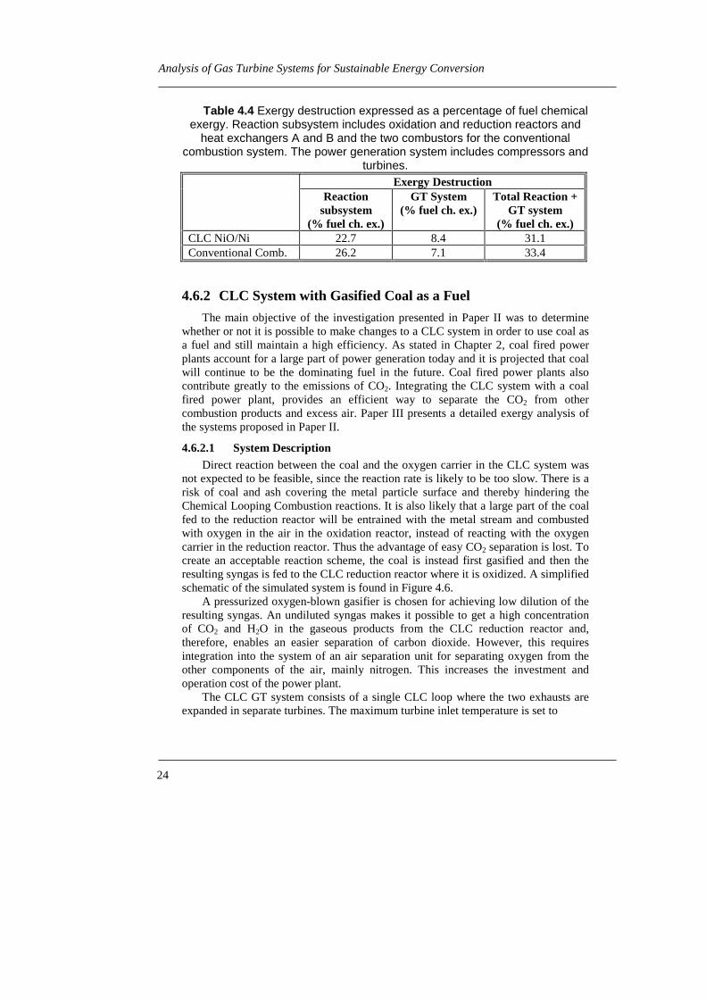
In Paper III, a detailed exergy analysis of the CLC gas turbine system with NiOas an oxygen carrier and the gas turbine system with conventional combustion ispresented. The Grassmann Diagrams in Figure 4.5 reveal the magnitude and locationof exergy destruction in these systems. In Table 4.4 the total exergy destruction in thedifferent subsystems is presented. The exergy destruction is less in the CLC reactionsystem than in the conventional combustion. The total exergy destruction includingpower generation is less using the CLC system than using the conventional system.
Table 4.3 Theoretical flow rates of solid per MW power produced. Thesolid mass and volume flow rates are based on NiO and Fe2O3 + ZrO2
respectively (Anheden, 1997). The volume flow does not include particlepores and bed voids.
Solid Power Density((kg/s)/MWe)
Solid Power Density((cm3/s)/MWe)
CLC with NiO 0.84 123CLC with Fe2O3 3.28 659

2323 23
Gas Turbine System with Chemical Looping Combustion
Power53.55%
Air0%
50.56%
Loss2.98%
Com
pres
sor
Ni89.67% O
xida
tion
Rea
ctor
A
Loss13.89%
NiO23.68%
102.66%
Tur
bine
1A
80.35%
Loss0.84%
Power21.47%
Exhaust 114.48%
Red
uct
ion
Rea
ctor
A
16.11%
Methane79.26%
HX A
Loss 4.33%
Exhaust 120.66%
Loss2.63%
Oxi
datio
n re
acto
r B
Hx B
Exhaust 13.97%
Loss 1.27%
Loss 0.13%
Methane21.68%
Loss0.46%
Loss0.07%
Mix
Loss0.004%
Red
B
Tur
bine
1B
Loss4.04%
Power33.38%
Power32.07%
Power1.90%14.66%
Tur
bin
e 2A
Exhaust 2a 12.69%
Tur
bine
2B
Loss0.43%Power
7.41%
Exhaust 28.73%
Exhaust 2b 1.94%
Exhaust 2b3.89%
Exhaust 126.32%
5.66%
Ni24.57%
NiO6.49%
Exhaust 195.81%
Exhaust 2a7.55% 16.58%
a)
Methane77.63%
43.06%Power45.60%
Air0% Loss
2.54%
Com
pres
sor
Com
bust
or 1
Loss21.11%
99.57%78.73%
Power20.06%
Tur
bine
1
Com
bust
or 2
Loss0.78%
Methane23.30%
Loss5.12%
Turb
ine
2
96.91%
Loss3.80%
Power37.96%
Exhaust29.61%
b)
Figure 4.5 Grassman diagrams. Exergy expressed as percentage of fuelchemical exergy. a) Chemical Looping Combustion GT system. b) GT system
with conventional combustion.
24
Analysis of Gas Turbine Systems for Sustainable Energy Conversion
Table 4.4 Exergy destruction expressed as a percentage of fuel chemicalexergy. Reaction subsystem includes oxidation and reduction reactors and
heat exchangers A and B and the two combustors for the conventionalcombustion system. The power generation system includes compressors and
turbines.Exergy Destruction
Reactionsubsystem
(% fuel ch. ex.)
GT System(% fuel ch. ex.)
Total Reaction +GT system
(% fuel ch. ex.)CLC NiO/Ni 22.7 8.4 31.1Conventional Comb. 26.2 7.1 33.4
4.6.2 CLC System with Gasified Coal as a Fuel
The main objective of the investigation presented in Paper II was to determinewhether or not it is possible to make changes to a CLC system in order to use coal asa fuel and still maintain a high efficiency. As stated in Chapter 2, coal fired powerplants account for a large part of power generation today and it is projected that coalwill continue to be the dominating fuel in the future. Coal fired power plants alsocontribute greatly to the emissions of CO2. Integrating the CLC system with a coalfired power plant, provides an efficient way to separate the CO2 from othercombustion products and excess air. Paper III presents a detailed exergy analysis ofthe systems proposed in Paper II.
4.6.2.1 System DescriptionDirect reaction between the coal and the oxygen carrier in the CLC system was
not expected to be feasible, since the reaction rate is likely to be too slow. There is arisk of coal and ash covering the metal particle surface and thereby hindering theChemical Looping Combustion reactions. It is also likely that a large part of the coalfed to the reduction reactor will be entrained with the metal stream and combustedwith oxygen in the air in the oxidation reactor, instead of reacting with the oxygencarrier in the reduction reactor. Thus the advantage of easy CO2 separation is lost. Tocreate an acceptable reaction scheme, the coal is instead first gasified and then theresulting syngas is fed to the CLC reduction reactor where it is oxidized. A simplifiedschematic of the simulated system is found in Figure 4.6.
A pressurized oxygen-blown gasifier is chosen for achieving low dilution of theresulting syngas. An undiluted syngas makes it possible to get a high concentrationof CO2 and H2O in the gaseous products from the CLC reduction reactor and,therefore, enables an easier separation of carbon dioxide. However, this requiresintegration into the system of an air separation unit for separating oxygen from theother components of the air, mainly nitrogen. This increases the investment andoperation cost of the power plant.
The CLC GT system consists of a single CLC loop where the two exhausts areexpanded in separate turbines. The maximum turbine inlet temperature is set to

2525 25
Gas Turbine System with Chemical Looping Combustion
ASU
AirSyngas
MeOMe
CLC-loop
GasifierSystemO2
Coal slurryAsh Sulfur
N2
Air
GT
GT
HRSG
ST
Excess Air
CO2 + H2O
Figure 4.6 Schematic process layout for CLC gas turbine combined cyclesystem with coal as fuel.
1280°C and turbine inlet pressure 17 bars; data likely to be used in future industrialgas turbines.
Three different oxygen carriers are tested, NiO, Fe2O3 and Mn3O4. The reactionschemes are as follows:
NiOO 0.5 + Ni 2 → (4.11)
NiOH 0.37CO 0.63NiOCH 0.0004H 0.36+CO 0.63 2242 ++→++ (4.12)
322 OFeO 0.5 + FeO 2 → (4.13)
FeO 2OH 0.37CO 0.63OFeCH 0.0004H 0.36+CO 0.63 223242 ++→++ (4.14)
432 OMnO 0.5 + MnO 3 → (4.15)
MnO 3OH 0.37CO 0.63OMnCH 0.0004H 0.36+CO 0.63 224342 ++→++ (4.16)
It is assumed that all reactions undergo 100% conversion of the fuel and oxygencarrier. These assumptions are verified through equilibrium composition calculations.
The basic CLC-loop layout used is the same as in Figure 4.3, however, somemodifications were necessary due to differences in the heat of reaction dependingupon which oxygen carrier is chosen and the fuel composition, Paper II. Unlike theother CLC systems presented, the reaction in the reduction reactor using Mn3O4 asthe oxygen carrier is exothermic, reaction (4.16). The reactor is cooled by re-circulating CO2 from the separation condenser to prevent the temperature fromexceeding the maximum temperature of 1280°C. The oxidation reaction, (4.15), alsoproceed with an adiabatic temperature of 1280°C.
To increase the overall power efficiency, the heat remaining in the CLC gasturbine system exhausts is used to generate steam in a heat recovery steam generator(HRSG) connected to a steam bottoming cycle. If CO2 separation is desirable, thewater vapor in the reduction reactor exhaust stream is condensed. The gaseousproduct, consisting mostly of CO2, can then be separated and disposed of in anenvironmentally safe way.

26
Analysis of Gas Turbine Systems for Sustainable Energy Conversion
4.6.2.2 ResultsThe main results from the simulations of the CLC GT systems using coal as a
fuel are presented in Table 4.5 and Figure 4.7. The results are based on a flow rate of15 kg coal/s into the gasifier, (LHV ≈ 25 MJ/kg). The performance of the CLC gasturbine combined cycle systems are compared to a gas turbine combined cyclesystem where the syngas is combusted in a conventional way. The potential ofgenerating additional power in a bottoming cycle has been estimated by calculatingthe physical exergy given up by the CLC system exhaust streams when cooling to100°C in the HRSG. The exergy of the heat removed in the syngas cooler in thegasification system has also been included.
First of all, comparing the net power output from the gas turbines in the CLC andconventional combustion systems, it is found that the CLC NiO and Mn3O4 systemsand conventional combustion system have power outputs in the same range. TheCLC Fe2O3 system has a 9% higher output than the conventional system. When thepotential of generating power in a bottoming steam turbine system is included, it isfound that the CLC NiO and Mn3O4 and the conventional combustion system haveoutputs in the same range, while the CLC Fe2O3 system has a somewhat lowermaximum output. The differences in power output diminish, as seen in Figure 4.7,
Table 4.5 Results from simulations of CLC and conventional combustion
systems with coal as fuel. GTTotW ,� stands for the total net power generated in
the CLC gas turbine system minus the power consumed in the ASU, Paper II.
GTTotW ,� (MW)
CLC NiO 120CLC Fe2O3 132CLC Mn3O4 118Conventional combustion 121
100
120
140
160
180
200
220
240
260
0 20 40 60 80 100Exergy Efficiency, Bottoming Cycle (%)
Wto
t (M
W) Ni
FeMnConv
Figure 4.7 Total net power generated by gas turbine and steam turbinesystems as a function of the exergy efficiency of the bottoming steam turbine
system, Paper II.
.

2727 27
Gas Turbine System with Chemical Looping Combustion
Table 4.6 Exergy losses in the reaction subsystem (oxidation andreduction reactor, heat exchanger alt. combustor) and power generation
system (compressor of air to combustor or oxidation reactor plus gasturbines). Losses expressed as a percentage of the syngas chemical exergy
at environmental temperature and pressure.Exergy Destruction
ReactionSubsystem
(% fuel ch. ex.)
GT System(% fuel ch. ex.)
Total Reaction+ GT System
(% fuel ch. ex.)CLC NiO 19.98 6.73 26.71CLC Fe2O3 20.07 8.79 28.87CLC Mn3O4 20.02 6.40 26.42Conventional comb. 22.88 6.51 29.38
when the exergy efficiency of which the physical exergy can be converted into powerin the steam turbine system is accounted for. In the range 60-67% exergy efficiency,which is a reasonable exergy efficiency for the bottoming cycle defined this way, allfour systems have similar power output.
A detailed analysis of the exergy destruction in the CLC gas turbine systemswith NiO and Fe2O3 is presented in paper III and with Mn3O4 in Anheden (1997).The resulting Grassmann Diagrams are found in these publications. In Table 4.6, thetotal loss of exergy in the reaction subsystem and power generation subsystem iscomputed, along with the total loss of exergy in the CLC GT system.
The losses caused by the reactions are significantly lower in all the CLC reactionsystems compared to the conventional combustion. If power generation is included inthe analysis, the Fe2O3 system is found to have higher exergy destruction in the gasturbines than the others, due to the high flow rate of air. Totally, the exergydestruction is lowest in the Mn3O4 CLC GT system followed by the NiO system. TheFe2O3 system has a somewhat higher total exergy destruction and the system withconventional combustion has the highest total exergy destruction of the systemsconsidered.
Simulation results also show that the mass and volume flow of solids in the NiOCLC system was significantly less than in the CLC systems with Fe2O3 or Mn3O4 asthe oxygen carriers.
4.7 Discussion of Results and ConclusionsThe present investigation explores the thermodynamics of simple gas turbine
cycle systems and combined cycle systems with Chemical Looping Combustion. Theeffect of using NiO, Fe2O3 and Mn3O4 as oxygen carriers is investigated.It has been generally observed that the combustion exergy destruction and the totalexergy destruction in the CLC gas turbine systems are less when using NiO, Fe2O3 orMn3O4 as oxygen carrier than the destruction observed in a gas turbine system withconventional combustion of the fuel. The electric efficiency for the CLC simple gasturbine system is in some cases higher than for a gas turbine system with

28
Analysis of Gas Turbine Systems for Sustainable Energy Conversion
conventional combustion. In these cases, heat from the GT exhaust has beenrecovered in the reduction reactor.
In a combined cycle application, the systems with CLC and conventionalcombustion have similar electric efficiencies, with a small potential advantage for theCLC systems. This indicates that there is only a minor thermodynamic advantage ofusing CLC in a combined cycle configuration. There are two main reasons why amajor advantage for CLC in a combined cycle system is not observed. First, a part ofthe exergy saved in the CLC process is in the form of a difference in concentrationbetween the constituents of exhaust streams and the environment. This exergy cannot be utilized for thermal power generation. Secondly, due to the increased heat ofreaction of the oxidation reaction relative to the conventional combustion reaction, ahigher flow rate of air is necessary to limit the temperature of the gaseous productstream to the maximum allowable turbine inlet temperature. This increased flow rateof air increases the loss of exergy with the exhaust stream leaving the HRSG at100°C. In the case of Mn3O4 as an oxygen carrier, the last observation does not hold,since the oxidation reaction is less exothermic than the conventional combustionreaction. The air flow rate is then lower than in the conventional combustion process.However, the higher inert gas flow rate for cooling the reduction reactor increases theexergy lost to the environment with the gaseous reduction reaction exhaust streaminstead.
The main advantage of CLC is considered to be connected to the integration ofCO2 separation into the combustion process. When including CO2 separation, it islikely that the CLC systems would have a lower energy penalty and a higher electricefficiency than a comparable system with conventional combustion combined withseparation of CO2. Theoretically, the only penalty connected to CO2 separation in theCLC process is the compression of CO2. This is only a very small part of the energypenalty for conventional power plants with CO2 separation reported in Table 3.1.
Of the oxygen carriers studied, NiO seems preferable. However, moreexperimental data is needed before a definite decision can be made in choosing theoptimal oxygen carrier. The performance of the plant using NiO as an oxygen carrieris satisfactory. The mass- and volume flow rates of the Ni oxygen carrier in its twooxidation forms are significantly lower than for the other oxygen carriers. Anotheradvantage of Ni is that it has fewer oxide forms than Fe and is therefore less sensitiveto changes in, for instance, temperature, excess air and pollutants that might alter thereaction path. Reactivity tests performed at Tokyo Institute of Technology alsoshowed a higher reaction rate and degree of conversion for Ni than for Fe. It was alsoshown that particles of Fe2O3 had a tendency to crack after repeated cycles ofoxidation and reduction, (Ishida and Jin, 1994b and 1997). As a consequence there isa risk of dust formation. This is undesirable since it can cause loss of oxygen carrierin the loop and in addition, the turbine is also very sensitive to solid particles in theexpanding gas stream. On the other hand, Ni is more expensive and has a morenegative effect on the environment than Fe. The lack of experimental data in the caseof Mn as an oxygen carrier makes it difficult to evaluate this option. However, nomajor thermodynamic advantage can be seen in using Mn.
Another area that should be addressed is the addition of inert material to theoxygen carrier. Even though the addition of this material has positive effects on the
2929 29
Gas Turbine System with Chemical Looping Combustion
reaction rate, the performance of the GT system is decreased. This is due to thetransportation of sensible heat from the oxidation reactor to the reduction reactorwith the inert material. This in turn decreases the possibilities of exhaust heatrecovery in the reduction reactor and thereby decreases GT cycle performance, asshown in Figure 7, Paper I. The same effect is seen if the oxidation conversionefficiency of the oxygen carrier is less than 100%.
A difference in thermodynamic performance of the CLC system is noticeddepending on fuel composition used. Using CH4 as a fuel improves the exhaust heatrecovery compared to using syngas. The reason for this is that the reaction betweenthe oxygen carrier and the syngas is less endothermic and, therefore, less exhaustheat can be recovered in the reduction reactor.
4.7.1 Identification of Critical Issues and Suggestions for FutureWork
During the modeling of the CLC systems, a number of assumptions have beenmade regarding the CLC systems’ performance. It is necessary to collect moreexperimental data under realistic conditions to be able to check the validity of theseassumptions. The simulation models can then be used to predict the full potential ofintegrating Chemical Looping Combustion in a power generation system moreaccurately. Among the critical operating parameters are reactor operatingtemperature, reaction kinetics, reaction conversion efficiency, reaction products andinduced pressure drops. The properties of the particle such as mechanical strength,porosity etc. are also of importance. Design of process equipment is another issuethat need careful considerations. Finally, optimization of the power generationsystem from both a thermodynamic and economic perspective including the specialimplications connected to separation of CO2 is necessary.
The operating temperature of the reactors and the induced pressure drops are twoof the critical operating parameters that directly affect the electric efficiency. Thetemperature in the oxidation reactor determines the turbine inlet temperature, whilethe temperature of the reduction reactor controls the temperature level of therecoverable exhaust heat. The operating temperature is, above all, dependent onwhich oxygen carrier is chosen. The temperature is limited by the melting orvaporization point of the solid constituents and the desired reaction products, reactionrates and degree of conversion. The pressure drop is primarily dependent on reactorconfiguration and the amount of solid material in the reactors.
The degree of conversion of the fuel in the reduction reactor is another importantconcern. If full conversion can not be realistically achieved, a way of separating andrecycling the unreacted fuel or some other way of utilizing the energy content of thefuel has to be found.
One of the most important issues deals with choosing an oxygen carrier. Thestudy presented in this thesis has focused on the thermodynamic effects of differentoxygen carriers. There are still other issues that need more thorough investigation.An oxygen carrier that has a sufficient rate of reaction for both the oxidation andreduction reaction needs to be found. Any side reactions, for instance carbonformation, that may occur need to be identified and avoided. Reactions leading to a

30
Analysis of Gas Turbine Systems for Sustainable Energy Conversion
deactivation of the oxygen carrier also have to be identified. If deactivation can notbe completely avoided, an oxygen carrier regeneration process might be necessary.The rate of sintering, agglomeration, and fragmentation of the solid material needs tobe investigated so that these rates can be kept to a minimum. Another issue to beaddressed is whether to use an inert material or not since the reactivity and strengthof the solid material is greatly affected by the material used. The inert material’s costand possible side reactions are also important. For instance, Ishida and Jin (1997)showed that carbon deposition from the fuel on solid particles of NiO/YSZ wasrelated to the zirconium-content of the particle. The size and structure of the particlesare also expected to have a significant influence on the reactivity, since the reactionrate is thought to be limited by transportation of reactants and products to and fromthe particle interior. Suitable particle manufacturing methods that give a highlyreactive particle suited for cyclic use in a CLC system need to be developed.
Most of the issues mentioned can only be resolved through experimental workunder realistic operating conditions. Therefore, one of the key issues to continue thiswork on CLC is to perform experiments. However, computer simulations can still beused to give information on the effect of certain design parameters on systemperformance and help in identifying desirable operating conditions.
Careful design of the equipment required for CLC is needed. The pressure dropover the reactors needs to be low since this directly affects the performance of thepower generation system. Development of high temperature filters that minimizes theemission of dust from the oxygen carrier is another important design problem.Experience with this type of filter can probably be collected from the development offilters for PFBC and IGCC plants.
Continued power generation system design and optimization and simulationsconcentrating on the implications associated with CO2 separation are required. If theprimary objective for using CLC is for its CO2 separation capability, a slightlydifferent plant configuration than the one described in this thesis might be preferable,since the CO2 is to be delivered at a high pressure (about 74 bars) for efficienttransportation and storage. By opting not to expand the exhaust from the reductionreactor, the CO2 leaves the system at a high pressure. The heat remaining in theexhaust could be utilized in the bottoming cycle. This scheme saves some power forCO2 compression and possibly increase the overall electric power conversionefficiency from fuel to CO2-disposal. TDA Inc. has estimated an energy penalty ofabout 5% for a similar configuration (DOE Fossil Energy, 1999).
Alternate ways of improving the gas turbine system’s performance should alsobe investigated, concentrating on heat recovery. Studies have, for instance, shownthat using a gas turbine system with humidification of the air and the fuel has apositive influence both on the power conversion efficiency through improved heatrecovery and decreases the rate of carburization of the oxygen carrier (Ishida and Jin,1994a, Bisio et al., 1998, Ishida and Jin, 1997, Ishida et. al, 1998).

3131 31
Closed and Open Externally Fired Gas Turbines for Power Generation from Biomass Fuels
5 Closed and Open Externally Fired GasTurbines for Power Generation fromBiomass Fuels
5.1 IntroductionThere are a number of thermal power technologies, both existing and under
development, which can be employed with a solid fuel like biomass. Most of theexisting biomass fired plants involve a steam-Rankine cycle; but in terms ofthermodynamic performance, cycles featuring gas turbines offer the greatest potentialfor high efficiencies compared to conventional steam-Rankine systems. Theintegrated gasification combined cycle (IGCC) is probably the most well knownemerging technology for integrating solid biomass fuels with gas turbines. However,a number of serious technical obstacles remain with IGCC, mostly related to gascleanup (i.e., elimination of particulates and reduction of alkali levels). As analternative to both steam-Rankine and IGCC technologies, externally fired gasturbine (EFGT) systems offer a number of advantages. For instance, since the gasturbine is indirectly fired, EFGT systems are capable of utilizing a variety of furnacetypes and pollution controls, including many of the well-proven technologiesfeatured in steam-based systems. Aside from higher efficiencies, EFGT systems havean advantage over steam-Rankine systems in that operating pressures are reduced(< 40 bar) and feed water treatment is not needed. Because the gas turbine in a EFGTcycle utilizes a clean working fluid, contamination of sensitive turbomachinerycomponents is much less of an issue as compared to IGCC.
Studies of externally fired gas turbines have been performed by a number ofdifferent research organizations and power equipment manufacturers. The main partof the research has been considering coal as the fuel, but lately, the use of biomassfuels has been gaining increased attention. This investigation has focused onexploring the use of EFGT cycles for biomass-fueled, small-scale cogeneration. Athermodynamic and economic performance analysis is presented for both open andclosed EFGT cycle configurations.
A number of externally fired gas turbines were built in Western Europe duringthe 1930’s to 1960’s. They were fueled with dirty fuels like coal, mine gas, blastfurnace gas etc. The gas turbines were built with a closed working fluid circuit andthe leading manufacturer was Escher Wyss AG, Switzerland. About 20 closed cyclegas turbines were built during this period. As the supply of cheap clean fuels likenatural gas and oil, suitable for direct combustion in the gas turbine, increased andthe trend for gas turbine inlet temperature increased, the interest in externally firedclosed cycle gas turbines faded. However, in the mid-1970s, as the decreased

32
Analysis of Gas Turbine Systems for Sustainable Energy Conversion
availability and subsequent increase in cost of clean fossil fuels were forecast to leadto an increased use of coal, various development activities of externally fired gasturbines were initiated in the United States. During this time, closed cycle gasturbines were also considered for power generation in high temperature gas coolednuclear reactors. Paper IV summarizes the development and operating experience onclosed cycle gas turbines together with equipment considerations. Information onclosed cycle gas turbines can also be found in McDonald (1985) and Pietsch (1985).
US Department of Energy, DOE, has in recent years supported developmentprograms for open externally fired gas turbines, including the Externally FiredCombined Cycle (EFCC) development program initiated in 1987. In addition, therelated Combustion 2000 program, together with the High Performance PowerSystem, (HIPPS) program were initiated in 1992. The companies that are or havebeen involved in different stages of the system and equipment studies are FosterWheeler, United Technologies, Hague International Stone & Webster, Allison andWestinghouse. In Europe, Ansaldo, ENEL (the Italian national utility) and researchinstitutions have been engaged in prospective studies of externally fired gas turbinessince 1992 with funding from the European Union (Consonni et al., 1996). TheNetherlands Agency for Energy and Environment has included EFCC in its NewEnergy Conversion Technologies Program (Korobitsyn, 1998). In Belgium, theTERMIE program of the European Commission and the VLIET program of theFlemish Government support a demonstration project of a combined heat and power(CHP) externally fired gas turbine plant. The plant is fueled by the product gas froma biomass gasifier (Marroyen et al., 1999). In Sweden, the Swedish National Boardfor Industrial and Technical Development (NUTEK) and later the Swedish NationalEnergy Administration (STEM) support studies of biomass fueled externally firedgas turbines. The studies include both EFCCs and evaporative externally fired gasturbine cycles (Yan et al., 1994, Eidensten et al., 1996) as well as the study of smallscale open and closed externally fired gas turbine systems presented in Papers V-VII.Yan (1998) and Korobitsyn (1998), have compiled summaries of the worldwideresearch on open EFGT cycles, together with a review of the predicted performanceof the different configurations.
5.2 Principal Description of Externally Fired GasTurbines
Figure 5.1 shows the directly fired gas turbine and the externally fired gasturbine. The externally fired gas turbine is different from the directly fired gasturbine in that the combustion process takes place outside the working fluid circuit.This has the following implications:
• The combustion process takes place at atmospheric pressure.• A high temperature heat exchanger is required to transfer heat to the gas turbine
working fluid.• Clean air is expanded through the turbine.

3333 33
Closed and Open Externally Fired Gas Turbines for Power Generation from Biomass Fuels
AirFurnace
HTHx
Cooler
Gaseous,clean fuel
Air
a) b)
Figure 5.1 a) Externally fired open or closed gas turbine. b) Directly firedgas turbine.
Because of this, it is possible to use a solid fuel without the complication of how tofeed it into a pressurized system. The demands on the quality of the combustionproducts (contents of solids, tars, corrosive components etc.), are decreased since theheat exchanger is less sensitive than the turbine. Low quality gaseous and solid fuelscan then be used without complicated clean-up equipment. There are two differentbasic configurations of the externally fired gas turbine, Figure 5.1a; the open cycleconfiguration and the closed cycle configuration as described in Chapter 3.2.
The challenge for the externally fired cycle is to develop a high temperature heatexchanger (HTHx) that is capable of supplying a high turbine inlet temperature, inaddition to withstanding the stresses imposed by the working conditions and theconstituents in the combustion gases. Two important issues to consider for using hightemperature heat exchangers are the size and cost of these units. The maximumallowable temperature is dependent on the furnace and heat exchanger material,configuration and the quality of the fuel, especially its ash chemistry. As a generalrule, nickel-based super alloys allow turbine inlet temperatures to reach 800-825°C.More advanced oxide dispersion (ODS) alloys can withstand temperatures ofapproximately 950°C up to 1100°C. A ceramic heat exchanger made from siliconcarbide composites is capable of operating at levels of 1000°C and is expected toallow levels of 1370°C in the future. In the open externally fired gas turbine cycle,additional clean gaseous fuel can be combusted in a topping combustor locatedbehind the high temperature heat exchanger, so called top-firing. This configurationincreases the turbine inlet temperature and thereby the thermal efficiency. The hightemperature heat exchanger designs that have been suggested include different typesof gas-gas heat exchangers or fluidized bed heat exchangers. More information abouthigh temperature heat exchanger materials and design is compiled in Paper IV,Yan (1998), and Korobitsyn (1998).
5.3 Objectives of EFGT StudyThe main objectives of the study on the closed and open externally fired gas
turbines presented in Papers IV-VII have been to:

34
Analysis of Gas Turbine Systems for Sustainable Energy Conversion
• Summarize previous research and operating experience on closed cycle gasturbines.
• Drawing on the conclusions from this review, suggest a closed externally firedgas turbine configuration suitable for the Swedish energy system and calculateits performance for a specified application.
• Examine the effects of using different working fluids in closed cycle gasturbines.
• Compare the performance of open and closed externally fired gas turbines.• Investigate the economic feasibility of the suggested systems.• Compare the thermodynamic and economic results from the EFGT study with
the thermodynamic and economic performance of present and emergingcompeting technologies.
The thermodynamic performance of the studied systems was calculated using theprocess simulation software Aspen Plus. The performance of the individual systemcomponents was estimated using state-of-the-art component efficiencies as reportedin Papers V-VII. Equipment size estimates were made using known correlations. Theequipment cost of the plants was estimated based on quotas from equipmentmanufacturers and other reliable sources.
5.4 Study of EFGT for Small-Scale CogenerationAfter completing the literature review, Paper IV, it was concluded that the most
suitable application for closed externally fired gas turbines, from a Swedishperspective, would be for small-scale, decentralized cogeneration of power and heatfrom a biomass fuel. It is not considered feasible to include a topping or bottomingpower cycle to increase the electric efficiency in this case. The high fuel utilizationresulting from cogeneration will compensate for the relatively low electric efficiencyimposed by the temperature limitations in the high temperature heat exchanger. Thegenerated heat could be utilized for district heating, which is already a commonpractice in Sweden today. The proposed gas turbine system could also be anattractive option in certain industries that already have a tradition of cogeneration,such as the pulp and paper industry or the lumber industry. Biomass is a CO2 neutral,domestic fuel that is presently available as a byproduct from the well-developedforest industry. A future possible change in the farming practice to production ofenergy crops would further increase the supply of biomass fuels. A plant size of<10 MWe is considered suitable for this study. In this size range, the gas turbinecycle would still be able to operate with a high electric efficiency, while theefficiency of the conventional steam Rankine cycle is low. The capital cost of theclosed cycle gas turbine plant is believed to be relatively low compared to a steamturbine plant of the same size.
5.4.1 System Configuration
Figure 5.2 illustrates the layout of the different system configurations consideredin this study.

3535 35
Closed and Open Externally Fired Gas Turbines for Power Generation from Biomass Fuels
Recuperator
Turbine LP Compressor HP Compressor
Air preheater
CFB furnace
Flue gas
Air
Biomass
1.
2.
3.
4.
Ash
10.
Fan
9.
7.2.
8.
7.2.
5. 6.
a)
Recuperator
Turbine LP CompressorHP Compressor
Air preheater
CFB furnace
Flue gas
Air
Biomass
1.
2.
3. 2.
4.
Ash
10.
Air
8.
Fan
V1
V27.2.
5. 6.
b)1. Flue gas condenser 5. First-level intercooler (IC1)2. District heat 6. Second-level intercooler (IC2)3. External bed heat 7. Cooling water exchanger (EBHX) 8. First-level postcooler (PC1)4. Flue gas heat exchanger 9. Second-level postcooler (PC2) (FGHX) 10. Flue gas condensate
Figure 5.2 Externally fired gas turbine cycles. a) closed configurationb) open configuration
A more detailed description listing the primary input parameters are found in PaperV, VI, and VII. A brief description of the combustion and gas turbine subsystems isgiven in the following chapters.
5.4.1.1 Combustion SubsystemAs shown in Figure 5.2, an atmospheric circulating fluidized bed (CFB) furnace
is selected for the combustion subsystem, as CFB furnace technologies featurepositive attributes such as fuel flexibility, high combustion efficiency, and inherentlylow NOx levels. A CFB furnace is also capable of combusting fuels with a highmoisture content, up to 60% (wt). In the systems in Figure 5.2, the combustionsection of the CFB furnace is refractory lined so the heat is transferred to the cycle

36
Analysis of Gas Turbine Systems for Sustainable Energy Conversion
via the flue gas heat exchanger (FGHX) and the external bed heat exchanger(EBHX). The CFB furnace is designed for solid biomass firing at a fuel input rate of7.7 MW (LHV) in the form of chips or sawdust. The size of the plant corresponds toa research-scale CFB plant located at Chalmers University of Technology inGothenburg, Sweden.
The design characteristics of the combustion subsystem are carefully chosenwith respect to corrosion/erosion issues and material availability. The two-stageheating in the FGHX and EBHX minimizes corrosive effects, since the highesttemperature heat exchange occurs in the EBHX using heated sand from the CFBinstead of the more aggressive products of combustion. The working fluidtemperature is limited to 550°C in the FGHX in order to keep tube temperatures atlevels where corrosion problems connected to the melting of alkali salts frombiomass are lessened. Even though the EBHX experiences the most severeconditions, high-grade steel alloys appear to be suitable because temperatures andpressures are relatively low (i.e., 850°C and 12 bar maximum). In addition, becauseof the high heat transfer rate in the EBHX, the unit’s size and cost can be reduced.
Lastly, the combustion air is preheated using heat from the flue gas. Theremaining heat in the flue gas is recovered for district heating purposes in the flue gascondenser. Here both the sensible and latent heat of the flue gas is utilized as the fluegas is cooled below its dew point and a part of the water content condensed. Flue gascondensation is also used for emission control. The condenser acts as an efficientparticle filter and some gaseous pollutants are also captured.
5.4.1.2 EFGT SubsystemIn keeping with future trends in gas turbine systems, various state-of-the-art
components have been selected for use with the EFGT cycles, Figure 5.2. A highperformance recuperator is used in combination with intercooling for enhanced heatrecovery. District heat is provided from the intercooler and postcooler at the sametime as the compressor inlet temperatures are lowered. The working fluid is heated to550°C in the FGHX. The final heating of the working fluid takes place in the EBHX.The maximum temperature of the working fluid is set to 800°C. Blade cooling of theturbine should therefore not be necessary. A pressure of 2 bar(a) has been assumedfor the low pressure compressor inlet, as this value balances heat transfer advantageswith the need to keep stresses at a minimum.
Two different operation options have been considered. In the one-level coolingmode, the district heating network provides for all the cooling. This places a limit onthe post- and intercooler working fluid outlet temperature to 65°C. Additionalcooling using 15°C cooling water is considered in the two-level cooling mode inorder to boost power output. The post- and intercooler working fluid outlettemperature is then reduced to 30°C.
The three working fluids chosen for the closed EFGT system shown inFigure 5.2(a) – helium (He), nitrogen (N2), and a helium/carbon dioxide (He/CO2)mixture – represent gases which are nontoxic, nonflammable, relatively low in cost,and compatible with a wide range of materials. These working fluids have beenselected based on previous investigations on the influence of gas turbine workingfluid on cycle performance, heat transfer, turbomachinery design etc. presented in

3737 37
Closed and Open Externally Fired Gas Turbines for Power Generation from Biomass Fuels
Chapter 4 of Paper IV. From a heat transfer point of view, He is advantageous sinceit has a high value of thermal conductivity, while N2 closely resembles air as aworking fluid, implying that standard turbomachinery could be more easily utilized.Even though N2 has similar thermodynamic and fluiddynamic properties as air, N2
provides a non-oxidative environment in the heat exchangers, which prohibitsoxidative corrosion. Previous studies identified a 60% He/40% CO2 mole fractionmixture as a working fluid which exhibits desirable characteristics related to heattransfer and turbomachinery requirements (Lee et al., 1982, Pierce 1981).
The open cycle configuration, Figure 5.2 b, allows for either series or parallelcoupling with the furnace. Valve V1 may be adjusted so that 100% combustion air isfed to the furnace via the gas turbine exhaust (series flow case, Air-s), while theremaining gas (about 80% of the total flow) is passed through the postcooler toproduce district heat. In contrast, the parallel flow case (Air-p) allows for the gasturbine and the furnace to operate independently.
5.4.2 Thermodynamic Results
5.4.2.1 Efficiencies as a function of Pressure RatioThe goal of the simulations was to determine the operating conditions yielding
maximum power output for each cycle configuration and working fluid under thegiven restrictions. With the fuel input fixed, the pressure ratio πr is thus the primaryvariable for analysis. Figure 5.3 illustrates three key subsystem performanceefficiencies as a function of πr for the CFB EFGT cycle system, using air andHe/CO2 as the working fluid.
In the performance analysis, electric efficiency is the key value of interest. It canbe shown that the electric efficiency, ηe, is equal to the product of the gas turbinecycle thermal efficiency, ηth,c, the furnace efficiency, ηf, and the generator efficiency,ηgen, eq. 5.1:
0,0
0,1
0,2
0,3
0,4
0,5
0,6
0,7
0,8
0,9
1,0
2,8 3,0 3,3 3,5 3,8 4,0 4,3 4,5 4,8 5,0 5,3 5,5 5,8 6,0
πr
η f
η th,c
T ap = 550 C T ap < 550 C
η e
Figure 5.3 EFGT cycle system thermodynamic performance versuscompressor pressure ratio, two-level cooling: closed symbols, He/CO2; open
symbols, air (parallel), Paper VI and VII.

38
Analysis of Gas Turbine Systems for Sustainable Energy Conversion
genfcthe ηηηη ⋅⋅= , (5.1)
The cycle thermal efficiency, defined as cycle power output divided by heat input tothe cycle, describes the cycle power conversion efficiency. The furnace efficiency,defined as the heat transferred to the cycle (in this case through the heat exchangersEBHX and FGHX) divided by the fuel supplied to the furnace, characterize thefurnace-to-cycle heat integration while the generator efficiency specifies thegenerators ability to transform mechanical power into electric power.
The cycle thermal efficiency shows a trend characteristic for recuperated cycles:after reaching a maximum, ηth,c continues to drop at higher pressure ratios due todecreased recuperation. Optimum conditions for the electrical efficiency do notnecessarily coincide with cycle thermal efficiency because of furnace-to-cycle heatcoupling. As can be seen from eq. 5.1, aside from a dependency upon cycle thermalefficiency, ηe is also dependent upon the amount of heat supplied by the furnace,which can be quantified by the furnace efficiency. At low pressure ratios, thetemperature at the recuperator cold side outlet is sufficiently high so that the amountof heat available to the cycle is limited. As the pressure ratio is raised, the cycle isable to extract increasing amounts of heat from the furnace, thus augmenting ηf andηe. A leveling out of these parameters occurs once the furnace air preheattemperature Tap falls below the design condition, as the heat input to the cycle beginsto level off at this point. For the configurations shown in Figure 5.3, this point isreached at πr = 5, and at higher pressure ratios ηe is relatively constant. Hence, thedesign point has been selected to correspond with this location.
Another key figure that describes the performance of the system is the totalefficiency. It is defined as the total usable energy leaving the system, i.e. in this casethe electric power plus the heat transferred to the district heating network, divided bythe fuel heat input. The simulations show that the total efficiency decreases withincreasing pressure ratio as the temperature of the flue gas entering the flue gascondenser decreases.
5.4.2.2 Results at Design Point Pressure RatioTable 5.1 shows the resulting thermodynamic performance for the different
system variations at the design point with component efficiencies according toPaper VI and VII.
Table 5.1 EFGT cycle thermodynamic performance results. Assumedcomponent efficiencies according to Paper VI and VII.
He He/CO2 N2 Air-series Air-parallelcooling 1 2 1 2 1 2 1 2 1 2πr 2.8 2.8 5.2 5.1 4.8 4.8 5.5 5.4 5.0 4.9
eW! (MW) 2.36 2.71 2.49 2.83 2.50 2.84 2.57 2.74 2.73 2.89
dhQ! (MW) 5.75 3.99 5.60 4.12 5.60 3.99 5.18 4.38 4.48 3.70
ηe 30.7 35.3 32.5 36.8 32.6 37.0 33.4 35.7 35.5 37.6ηtot 105.5 87.2 105.4 90.4 105.5 89.0 100.8 92.7 93.8 85.7

3939 39
Closed and Open Externally Fired Gas Turbines for Power Generation from Biomass Fuels
The value of πr at the design point depends primarily on the specific heat ratio,γ = cp/cv, of the working fluid used, with a high value on γ giving a low πr. Thespecific heat ratio for He is 1.67 while it varies between 1.3 and 1.4 for the otherworking fluids.
Influence of Working Fluid and Cooling for Closed CyclesFor the closed EFGT cycles, He shows slightly lower electric efficiency
compared to the He/CO2 mixture and N2, which have nearly identical values. Withrespect to power output, the best performance is achieved with two-levelpost/intercooling, which results in an increase in electrical efficiency of nearly fivepercentage points for each of the cases considered (i.e. 35-37% (LHV) as comparedto 31-33%) due to the lower compressor inlet temperatures. On the other hand, one-level post/intercooling maximizes the total efficiency (ηtot), as additional district heatis produced in favor of electricity. The total efficiency is 106% (LHV) with one-levelcooling compared to 87-90% with two-level cooling (ηtot can rise above 100% sinceflue gas condensation is employed). With one-level cooling, all the heat supplied tothe cycle is either converted to power or used for district heating. However, withtwo-level cooling, heat is rejected to the environment with the cooling water, thuslower total efficiencies are seen. With one-level cooling, the total efficiency isindependent of the working fluid. However, with two-level cooling, a certainvariation in total efficiency is observed with respect to working fluid used. Thisobservation is explained by the different behavior of the working fluids’ specific heatcapacity, cp, on variations in temperature. The mass flow rate of the working fluid isdetermined so that the working fluid temperature in the EBHX is increased from 550to 800°C with a constant heat duty at the design point. From an energy balance forEBHX, it can be concluded that pcm ⋅� over EBHX has the same value regardless of
the working fluid. At lower temperature levels, the cp for N2 and CO2 decreases whileit remains constant for He. As a consequence, the heat loss with the cooling waterwhen cooling from 65°C to 30°C in the inter- and postcooler is lower with N2 andHe/CO2 as the working fluid than with He.
Open vs. Closed CyclesIn comparing open and closed cycle configurations, it is generally found that the
closed EFGT cycles have a higher total efficiency. In the closed cycles, the heatremaining in the exhaust exiting the postcooler is recycled and brought to a highertemperature level through compression, as opposed of being vented to theatmosphere as in the open cycle. On the other hand, the open EFGT cycles have ahigher electric efficiency due to the lower LP compressor inlet temperature (ambienttemperature). The exception to this general observation is in the series connectedopen EFGT cycle with two level cooling. In this case, the electrical efficiency islowered due to the higher turbine back-pressure required to overcome the CFBfurnace pressure drop, and the total efficiency is increased because turbine exhaust isused as combustion air.
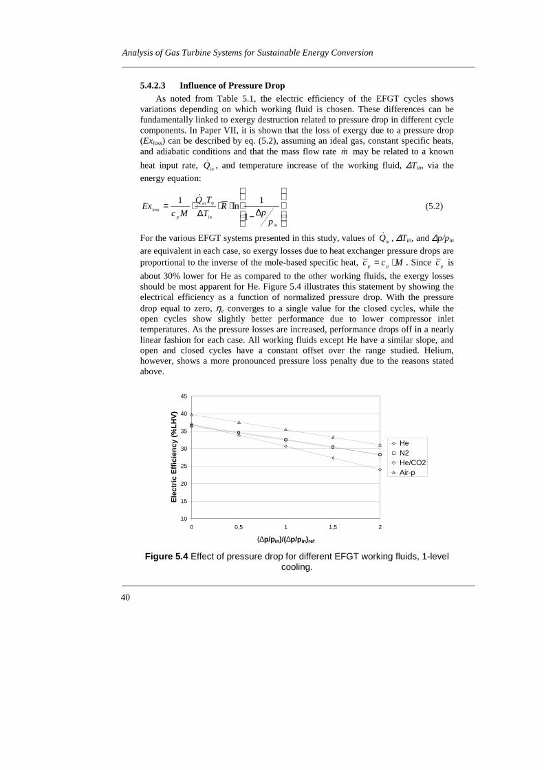
40
Analysis of Gas Turbine Systems for Sustainable Energy Conversion
5.4.2.3 Influence of Pressure DropAs noted from Table 5.1, the electric efficiency of the EFGT cycles shows
variations depending on which working fluid is chosen. These differences can befundamentally linked to exergy destruction related to pressure drop in different cyclecomponents. In Paper VII, it is shown that the loss of exergy due to a pressure drop(Exloss) can be described by eq. (5.2), assuming an ideal gas, constant specific heats,and adiabatic conditions and that the mass flow rate m� may be related to a known
heat input rate, inQ� , and temperature increase of the working fluid, ∆Tin, via the
energy equation:
∆−⋅⋅
∆⋅=
in
in
in
p
loss
pp
RT
TQ
McEx
1
1ln
1 0�
(5.2)
For the various EFGT systems presented in this study, values of inQ� , ∆Tin, and ∆p/pin
are equivalent in each case, so exergy losses due to heat exchanger pressure drops areproportional to the inverse of the mole-based specific heat, Mcc pp ⋅= . Since pc is
about 30% lower for He as compared to the other working fluids, the exergy lossesshould be most apparent for He. Figure 5.4 illustrates this statement by showing theelectrical efficiency as a function of normalized pressure drop. With the pressuredrop equal to zero, ηe converges to a single value for the closed cycles, while theopen cycles show slightly better performance due to lower compressor inlettemperatures. As the pressure losses are increased, performance drops off in a nearlylinear fashion for each case. All working fluids except He have a similar slope, andopen and closed cycles have a constant offset over the range studied. Helium,however, shows a more pronounced pressure loss penalty due to the reasons statedabove.
10
15
20
25
30
35
40
45
0 0,5 1 1,5 2
(∆p/pin)/(∆p/pin)ref
Ele
ctri
c E
ffic
ien
cy (
%L
HV
)
HeN2He/CO2Air-p
Figure 5.4 Effect of pressure drop for different EFGT working fluids, 1-levelcooling.

4141 41
Closed and Open Externally Fired Gas Turbines for Power Generation from Biomass Fuels
5.4.2.4 Influence of Component EfficienciesThe results presented in Table 5.1 are obtained while assuming rather high but
still realistic component efficiencies. The influence on the electric efficiency of thesecomponent efficiencies is of interest.
The turbomachinery, i.e. compressors and turbine, efficiency has a stronginfluence on the electric efficiency by decreasing the cycle thermal efficiency,eq. 5.1. A difference of 6-8 percentage points in electric efficiency is found when theelectric efficiencies obtained in Paper V, with assumed compressors and turbineisentropic efficiencies of 0.85, are compared with the results obtained in Paper VIand VII, with polytropic turbine and compressor efficiencies of 0.90. (A polytropicefficiency of 0.90 is at the design point in the cases studied approximately equivalentto a compressor isentropic efficiency of 89% and a turbine isentropic efficiency of92%).
By observing Figure 5.4, it can be concluded that the electric efficiency is greatlyaffected by the pressure drops induced in the heat exchangers. The numerous heatexchangers make the system very sensitive to this loss. As mentioned inChapter 5.4.2.3, using He as working fluid further increases the sensitivity topressure drops, compared to the other working fluids studied.
The effectiveness of the recuperator affects the internal heat recovery in the cyclewhich in turn affects the cycle thermal efficiency and thereby the electric efficiency.The sensitivity analysis in Paper V shows that when the effectiveness is decreasedfrom 0.95 to 0.90 the electric efficiency decreases with less than 0.5 percentagepoints.
The influence of the air preheating temperature has also been investigated. Thisparameter influences the exhaust heat recovery and thereby the furnace efficiency.Simulations have shown that the electric efficiency is lowered by approximately2 percentage points for every 100°C decrease in air preheat temperature.
5.4.3 Size of Equipment
The size of the gas turbine cycle equipment as a function of the working fluidused is investigated in Paper VI. The size of the equipment is of interest since it hasan influence on the cost of the plant.
The size of all of the heat exchangers in the cycle has been calculated, assumingequivalent relative pressure drops regardless of working fluid and configuration,Figure 5.5. In general, the largest total heat transfer areas result when two-levelpost/intercooling is utilized. The closed cycle configuration is especially sensitive inthis circumstance, as two additional heat exchangers are required for increasedcooling. Cycle configuration and working fluid have little influence on the FGHXsize, since heat transfer is limited on the flue gas side rather than the tube side, asseen in Figure 5.5. For the other components, heat transfer depends more strongly onthe cycle-side characteristics, as the EBHX, postcoolers, and intercoolers have largefilm coefficients external to the cycle. In this instance, He exhibits the smallest areas,although the He/CO2 mixture has comparable values. Cycles featuring N2 or air,conversely, require more substantial heat transfer areas, especially with respect topostcoolers and intercoolers. He features the smallest recuperator size, and the

42
Analysis of Gas Turbine Systems for Sustainable Energy Conversion
differences between the working fluids roughly correspond to those shown withpostcoolers and intercoolers, Paper VI.
Simplified analytical techniques derived from Cohen et al. (1986) and Hunter(1994) have been used to calculate the dimensions of the turbomachinery to form abasis for comparison of the influence of the working fluid on this component group.The number of stages required for the turbine and compressors and their approximatedimensions are shown in Paper VI. As illustrated in Figure 5.5, turbomachinery sizeis most closely related to the type of working fluid used. The small difference seenbetween the number of stages and dimensions of the closed cycle gas turbine with N2
as the working fluid and the two open cycle gas turbines is related to the lowervolumetric flow rate resulting from pressurization of the closed cycle. Heliumrequires about three to four times the number stages compared to the open cycles forboth the turbine and the compressors, which is mainly due to its high specific heat.
The size of the heat exchangers and the turbomachinery can be further reducedfor closed cycle gas turbines by increasing the absolute pressure level. In Paper VII,it was found that the heat transfer areas in some heat exchangers could be reduced bya factor of 2-3 from the baseline case when the maximum pressure was set to 30 bars.However, this does not necessarily translate into cost reductions. Operating atelevated pressures increase the requirements on the strength of the material andmight decrease component efficiencies which leads to increased cost and decreasedthermodynamic performance.
0
50
100
150
200
250
300
350
400
FGHX EBHX PC1 PC2 IC1 IC2
Are
a (m
2 )
He
He/CO
N
air (series)
air (parallel)
2
2
0
2
4
6
8
10
12
LPCompressor
HPCompressor
Turbine
Num
ber
of S
tage
s He
He/CO
N
air (series)
air (parallel)
2
2
Figure 5.5 Size of heat exchangers and number of compressor andturbine stages, two-level cooling.

4343 43
Closed and Open Externally Fired Gas Turbines for Power Generation from Biomass Fuels
Although He has been shown to have the best performance in terms of heatexchanger size, the necessity of more complex turbomachinery may negate thisbenefit. The system featuring a He/CO2 mixture lies between the two extremes. Itrequires about half the number of compressor and turbine stages compared to thepure He case. Additionally, the heat transfer area required is less than for air and N2
working fluid.
5.4.4 Economics
Paper VII accounts for an approximate economic analysis of the externally firedgas turbine cycle systems.
An estimate of the installed equipment cost for each EFGT system configurationwas performed by collecting information from equipment manufacturers and otherreliable sources. The costs presented are for the first plant built and does thereforenot include any advantages of mass production.
The calculated installed equipment costs for the 8 MWf plant with differentworking fluids and configurations ranges from 7.3 to 7.9 M$, with the lowest cost forHe one-level cooling and the highest cost for Air-s two-level cooling. Calculationsshow that specific total plant costs range from 3300-3800 $/kWe. The error range forthese estimations is estimated to be ± 20%. Further details on these calculations,together with the individual equipment costs, may be found in a report byAnheden (1999).
The total plant costs are relatively independent of the particular EFGT systemconfiguration. An investigation of how the total installed equipment cost is dividedbetween the different components shows that the CFB furnace and the powergenerating equipment make up the major part of the installed equipment cost. TheCFB furnace and the power generation equipment each contribute with about 1/3 ofthe total equipment cost for all of the EFGT systems studied. The cycle-side heatexchangers comprise 12-17% of the total equipment cost, depending on workingfluid and cycle configuration. When exploring the influence of the working fluid, itcan be seen that the closed cycle gas turbine systems with non-conventional workingfluids have lower heat exchanger costs (and marginally lower total costs) due to thebenefits of pressurization and higher heat transfer coefficients.
The economic viability of the EFGT systems is determined by calculating thecost of electricity, (COE), for the different plant configurations. An estimate of theCOE can be obtained by assuming that this cost is made up of four terms: capitalcharges based on annualized total plant cost; fuel cost; operation and maintenancecosts; and return on district heating. District heat credit is calculated from theavoided costs for purchasing and running a biomass fueled hot water boiler. Theresulting COE as a function of operating hours is found in Figure 5.6 together withthe crediting used for district heat, (COH). A 5% interest rate and 25 years economiclife are used in the calculations.
As can be seen, COE is strongly dependent on the annual full load hours. Thismeans that it is important to have high plant availability and a high demand of theproducts, i.e. heat and power, during a major part of the year. The average annualoperating period for this kind of municipal heat and power production plant inSweden is approximately 4000-5000 full load hr/yr.

44
Analysis of Gas Turbine Systems for Sustainable Energy Conversion
40
50
60
70
80
90
100
110
3000 4000 5000 6000 7000 8000
Annual full load hours
CO
E (
$/M
Wh
e)
10
15
20
25
30
35
CO
H (
$/M
Wh
h)
He-2N2-2He/CO2-2Air-p-2Air-s-2He-1N2-1He/CO2-1Air-p-1Air-s-1HWC
Figure 5.6 COE as a function of operating hours for 8 MWf EFGT cyclesystems and the COH used for crediting of produced district heat (suffix 1 or
2 used to denote level of cooling).
A higher operating time is expected if the plant is used for industrial cogeneration,with a demand for process heat throughout the year instead of just during the coldseason. A possible application lies with the sawmill industry with a heat demand thatwould cover operating times of up to 7000-8000 hr/yr. Comparing the different plantconfigurations, the closed cycles with one-level post- and intercooling reveals thelowest COE, with a cost of about 75-60 $/MWhe for 4000-5000 hr/yr. The calculatedCOE for the open cycle configurations with one level post/intercooling is somewhathigher, ranging between 81-67 $/MWhe, for the same operating time. Using two levelcooling results in a slightly higher COE primarily due to the lower district heatgeneration. With 7000 hr/yr, the COE is about 49-58 $/MWhe.
One major uncertainty in the analysis is the cost of the turbomachinery for theclosed cycle gas turbines, especially with He and He/CO2 working fluid. The samecost has been used for all turbomachinery in the above analysis. However, in additionto the costs associated with added stages in the case of He and He/CO2 working fluid,the necessity of having specially designed turbomachinery will also increase the costof this component. It is, therefore, of interest to determine the allowableturbomachinery cost increase leading to a maximum allowable penalty in COE.Results show that with 4000 full load hours per year, the additional cost ofturbomachinery for He or He/CO2 working fluid should be limited to approximately25% of the baseline turbomachinery cost in order to keep total plant costs below areasonable margin. For N2 working fluid, a modest modification of existingturbomachinery is expected, since the thermophysical properties of N2 are similar toair. The closed cycle gas turbine with N2, however, operates at a higher pressure atthe compressor inlet and turbine outlet (2 bar(a)), leading to a reduction in size via amore favorable volume-specific power output. It is estimated that this improvement,in economic terms, would translate into a slight reduction (about 5%) in total specificplant cost and COE.

4545 45
Closed and Open Externally Fired Gas Turbines for Power Generation from Biomass Fuels
One of the major discussions during the course of collecting economic data wasdetermining the material needed for the EBHX. After consultation with equipmentmanufacturers, stainless steel SS2333-23 was finally selected since the sulfur contentof the fuel is low and erosion was thought to be of greatest concern. However, shoulda more exclusive alloy be required, the cost of the EBHX is estimated to increase byup to a factor of three. A sensitivity analysis shows that increasing the EBHX cost bythis factor raises the capital cost by less than 5%, which also leads to a similarincrease in COE with an operating period of 4000 hr/yr.
5.4.5 Comparison with Other Biomass Based Technologies
To place the thermodynamic and economic results presented for the 8 MWf
EFGT systems into perspective, a comparison is made to conventional and emergingtechnologies for small-scale heat and power generation from biomass fuels. Theselected configurations for comparison include conventional steam turbinecogeneration plants, with and without flue gas condensation. A small-scale IGCCplant and a diesel engine plant fueled with a vegetable oil have also been included inthe study, as they represent emerging technologies for biomass-based cogeneration.A comparison is also made with an existing 3 MWe steam turbine plant in Malå,Sweden, which has nearly the same size as the EFGT systems considered in thisstudy. However, the Malå plant does not have a flue gas condenser. The thermal andeconomic data for these systems are summarized in Table 5.2.
Comparing the electrical efficiency of the EFGT plants, Table 5.1, with thesteam turbine plants shows that the 2.5-3 MWe EFGT cycles are capable of reachingelectrical efficiencies that are on the same level as a 50 MWe steam turbine plant incogeneration operation; moreover, high total efficiencies are retained. The electricalefficiency of the EFGT plants is, however, lower than that of the IGCC plant and thediesel engine, although total efficiencies are higher.
To be able to compare the different plant configurations’ total efficiency whiledistinguishing between heat and power generation, a dimensionless number calledcogeneration effectiveness, κ, based on fuel consumption has been developed. It isdefined as the extra fuel required for separate generation of power and heat, dividedby the fuel consumption in the cogeneration plant, eq (5.3).
Table 5.2 Thermal and economic data for small-scale biomasscogeneration plants. Data for the first five alternatives has been taken fromAleberger et al. (1995), while the data for the last alternative is reported by
Sjöö (1998).Bio ST
1KBio ST
2KBio ST
3KBio-IGCC Bio Diesel
(Veg. Oil)Malå
Bio STElectric power (MW) 25 50 10 30 9 3District heat (MW) 62 125 30 30 10 11Electric Efficiency (%LHV) 31 31 27 42 37 18Total Efficiency (%LHV) 110 110 108 85 80 85Investment ($/kWe) 2 200 2 005 2 329 3 234 1 100 3 019

46
Analysis of Gas Turbine Systems for Sustainable Energy Conversion
Table 5.3 Cogeneration effectiveness. Numbers in parenthesis refer totwo-level cooling. Reference values, ηel, ref = 42% (LHV) (150 MWe
condensing Bio ST cycle), ηdh, ref = 110%, Paper VII.EFGT
N2
EFGTair-s
EFGTair-p
Bio ST3K
Bio ST2K
MalåST
Bio-IGCC
κ 0.44 (0.35) 0.41 (0.37) 0.38 (0.33) 0.38 0.46 0.04 0.40
1,,,
,,, −−
+=−+
=refdh
etot
refe
e
cogenf
cogenfdhfelf
Q
QQQ
ηηη
ηη
κ�
���(5.3)
The calculated number gives the fuel saved through cogeneration as opposed toseparate generation, per fuel input to the cogeneration plant. These fuel savings canbe translated into reductions in emissions of environmentally harmful substances andconservation of fuel resources. The calculated κ:s for the solid biomass fueled plantsare found in Table 5.3. The cogeneration effectiveness of the EFGT plants compareswell with both the steam turbine plants and the IGCC plant. The closed EFGT cyclearrangement seems to be preferable to the open cycle arrangement, and one-levelcooling better than two-level cooling, from this perspective, since theseconfigurations give a higher value on κ. The cogeneration effectiveness of the Malåplant appears to be low, which is mostly due to the lack of flue gas condensation.
An economic comparison between the different biomass-fired plants has alsobeen conducted, as illustrated in Figure 5.7. The COE for the EFGT systems is about80% higher than the 10-50 MWe conventional steam-based technology whenconsidering an operating period of 4000-5000 hr/yr. If a comparison is made betweenthe EFGT systems and the small scale Malå plant, the difference in COE is reducedto about 30%. It is noteworthy that both the IGCC plant and the diesel engine-basedalternative have higher COE’s (about 30% and 170%, respectively) than the EFGTsystems. The extremely high costs associated with the diesel engine-based system areprimarily due to the expense of the vegetable oil, (75 $/MWhf as opposed to13.75 $/MWhf for solid biomass fuel). The IGCC plant is penalized by its highcapital cost and low district heating production resulting from a low total efficiency.The high capital cost is the main reason for the high COE of the EFGT plants incomparison with steam turbine plants. The EFGT plant capital cost is, however,expected to decrease if these plants are put into mass production.
In order to compare the plants on a more equal basis, the EFGT systems arescaled to match the size of the Bio ST 3K plant and the IGCC plant in terms ofdistrict heat production (30 MWdh), keeping electrical and total efficiencies constant,Paper VII. In addition, a second resizing of the EFGT is considered whereby the fuelinput is matched to that of the Malå plant. (Scaling based on district heat output is notappropriate here since the Malå plant does not utilize flue gas condensation.) Thecomparison shows that the COE for the EFGT systems lies in the same range as thesteam turbine plant, especially for intermediate or prolonged yearly operating hours,Paper VII. The EFGT systems have a definite advantage when compared to IGCC atthis size, as the COE’s are only half as large. Favorable COE’s are also demonstratedfor the EFGT systems as compared to the Malå plant.
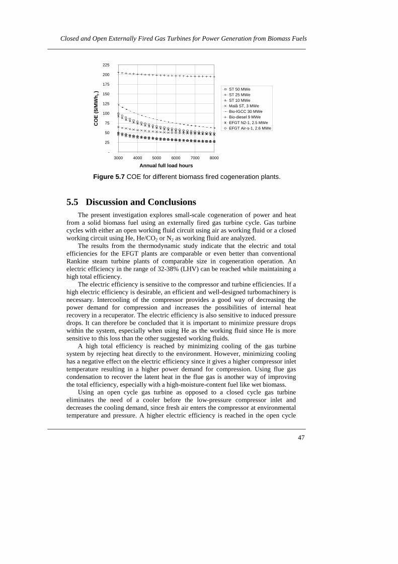
4747 47
Closed and Open Externally Fired Gas Turbines for Power Generation from Biomass Fuels
-
25
50
75
100
125
150
175
200
225
3000 4000 5000 6000 7000 8000
Annual full load hours
CO
E (
$/M
Wh e
) ST 50 MWeST 25 MWeST 10 MWeMalå ST, 3 MWeBio-IGCC 30 MWeBio-diesel 9 MWeEFGT N2-1, 2.5 MWeEFGT Air-s-1, 2.6 MWe
Figure 5.7 COE for different biomass fired cogeneration plants.
5.5 Discussion and ConclusionsThe present investigation explores small-scale cogeneration of power and heat
from a solid biomass fuel using an externally fired gas turbine cycle. Gas turbinecycles with either an open working fluid circuit using air as working fluid or a closedworking circuit using He, He/CO2 or N2 as working fluid are analyzed.
The results from the thermodynamic study indicate that the electric and totalefficiencies for the EFGT plants are comparable or even better than conventionalRankine steam turbine plants of comparable size in cogeneration operation. Anelectric efficiency in the range of 32-38% (LHV) can be reached while maintaining ahigh total efficiency.
The electric efficiency is sensitive to the compressor and turbine efficiencies. If ahigh electric efficiency is desirable, an efficient and well-designed turbomachinery isnecessary. Intercooling of the compressor provides a good way of decreasing thepower demand for compression and increases the possibilities of internal heatrecovery in a recuperator. The electric efficiency is also sensitive to induced pressuredrops. It can therefore be concluded that it is important to minimize pressure dropswithin the system, especially when using He as the working fluid since He is moresensitive to this loss than the other suggested working fluids.
A high total efficiency is reached by minimizing cooling of the gas turbinesystem by rejecting heat directly to the environment. However, minimizing coolinghas a negative effect on the electric efficiency since it gives a higher compressor inlettemperature resulting in a higher power demand for compression. Using flue gascondensation to recover the latent heat in the flue gas is another way of improvingthe total efficiency, especially with a high-moisture-content fuel like wet biomass.
Using an open cycle gas turbine as opposed to a closed cycle gas turbineeliminates the need of a cooler before the low-pressure compressor inlet anddecreases the cooling demand, since fresh air enters the compressor at environmentaltemperature and pressure. A higher electric efficiency is reached in the open cycle

48
Analysis of Gas Turbine Systems for Sustainable Energy Conversion
system when the environmental temperature is lower than the compressor inlettemperature of the closed cycle system, assuming all the other parameters are thesame. However, the total efficiency of the open cycle system is lower since sensibleheat leaves the open system with the exhaust.
Using a closed gas turbine cycle system allows for pressurization of the low-pressure side of the gas turbine and thereby more compact and possibly lessexpensive equipment. The closed cycle arrangement improves the part loadperformance of the system, which is of importance if the system is expected tooperate at part load for extended periods of time.
Using a CFB furnace to supply the heat to the EFGT system seems to be atechnically reliable solution. CFB combustion gives low emissions and is suitable forsolid, high moisture content fuels like biomass, peat or solid waste products. Lettingthe final heating of the working fluid take place in an external fluidized bed heatexchanger where the heating is provided by the sand from the CFB-furnace preventsdirect contact between the corrosive flue gases and the high temperature heatexchanger material. Corrosive and fouling effects should therefore be decreasedcompared to gas- to flue gas heat exchangers. The high heat transfer rate in theexternal fluidized bed also decreases the heat transfer area requirements and the costof this piece of equipment compared to a gas-gas heat exchanger.
It has been shown that of the working fluids studied, He requires less cycle sideheat transfer area relative to the other suggested working fluids. However, thenumber of stages on the turbine and compressor is increased. The He/CO2 mixtureoffers a good combination of small heat transfer area and reasonable number ofcompressor and turbine stages. Using N2 as the working fluid, on the other hand,makes it easier to use standard turbomachinery designed for air as the working fluidwhile the risk of oxidative corrosion is decreased.
The economic analysis shows the major part of the equipment cost is made up ofthe CFB furnace and the power generating equipment. The total plant cost isestimated to 3.3-3.8 k$/kWe for a first commercial plant. It is not likely that thedecrease in heat exchanger cost, in the case of using He or He/CO2 mixture as theworking fluids, outweighs the cost of redesigning the turbomachinery for a small-scale plant. Therefore, a closed cycle system using N2 or air as the working fluid oran open cycle system seems to be the most preferable options.
The cost of electricity is estimated to 73-84 $/MWhe for 4000 hr/yr of full loadoperation for the 8 MWf cogeneration plant. EFGT plants offer the advantage of ahigher electric efficiency at a comparable or possibly lower COE when compared toconventional steam turbine plants in a small scale (<10 MWe). A lower COE isshown in comparison with a small-scale IGCC plant or a vegetable oil fueled dieselengine. The COE of the 8 MWf plant seems high when compared to the estimatedCOE of 30-40 $/MWhe of new fossil fuel based power plants or the 1998 averageprice of electricity of about 15 $/MWhe on the spot market at the Nordic PowerExchange, Nordpool, (Swedish National Energy Administration, 1999). A subsidy orhigher costs of fossil fuels, for instance through an increased CO2 tax, is needed tomake power generation with biomass fuels in this scale profitable. Another case thatwould make the small scale EFGT cycle economically competitive is if the fuel couldbe obtained practically free of charge as a waste product from an industrial operation.

4949 49
Closed and Open Externally Fired Gas Turbines for Power Generation from Biomass Fuels
It is also important to remember that the economical evaluation of the EFGT planthas been made for a single-unit plant. Mass production of the plant is likely to furtherreduce the capital cost and thereby make it more cost competitive.
5.5.1 Suggestions for Future Work and Identification of CriticalIssues
The development of high temperature material and the design and constructionof high temperature heat exchangers are believed to be the main areas of futureresearch and development of externally fired gas turbine systems. Construction of acombustion system that minimizes the risks of fouling and corrosion of the heatexchanger is desirable. The integration between the high temperature heat exchangerand the combustion device is another important area to be investigated.
Different schemes for integration of a heat recovery system with the gas turbinecycle system and the combustion system should be further examined. A study onevaporative heat recovery through humidification of the gas turbine working fluidhas been performed (Ahlroth et al., 2000). The study shows that a slight increase inelectric efficiency can be expected.
It might turn out to be more appropriate to optimize the gas turbine system withrespect to low equipment cost rather than electric efficiency. The use of inexpensivebut less efficient equipment such as a low-cost turbine and compressor system basedon turbo charger technology could prove to be economically viable. Intercooling ofthe compressor through injection of water that evaporates rather than using anintercooler heat exchanger is another idea that has been suggested but not yetexamined from an economic point of view, (Bardi, 1999).
Regarding the closed cycle gas turbines, the turbomachinery needs to bemodified to allow for efficient operation with a positive pressure at the compressorinlet and turbine outlet. If a working fluid with fluid properties other than air is used,the compressor and turbine require redesigning.
It is necessary to develop a dynamic model of the EFGT plant. This would allowstudies of operational transients. A control system needs to be specially designed forEFGT plant. A procedure for start-up, shut-down and load changes have to beidentified. If a CFB furnace like the one proposed in this thesis is to be employed,development of an advanced control system is necessary so that the temperaturefluctuations in the CFB can be controlled.
The most critical issue for a commercial breakthrough for externally fired gasturbines today is the successful operation of a demonstration plant. Proven highavailability and reliability of the combustion system and the high temperature heatexchanger are of vital importance, since these are critical issues that affecting thewillingness to invest in this technology.

50
Analysis of Gas Turbine Systems for Sustainable Energy Conversion
6 Concluding Remarks
It is notoriously difficult to predict the future, but that should not stop us frommaking our plans on the basis of where present trends are leading us and consideringwhat actions or events could alter these trends. Reductions in the use of fossil fuelresources and other measures to prevent rapid changes in the climate due togreenhouse gas emissions are today thought to be necessary to provide for asustainable development. Although the effects of increased CO2 levels on globalclimate are uncertain, there is scientific consensus that a significant increase ofatmospheric CO2 concentrations could have a variety of serious environmentalconsequences. We, therefore, need to continue to develop efficient energy conversionprocesses and utilize renewable energy sources so that we can save fuel resourcesand reduce environmentally harmful emissions related to human activities.
Using Chemical Looping Combustion to provide for energy efficient separationof CO2 from power plants using fossil fuels is one of many promising technologies inthe transaction to a energy system built on renewable, CO2 neutral energy sources.Developing technologies like externally fired gas turbine power plants for efficientcogeneration of power and heat from a renewable and CO2 neutral solid biomass fuelwith high overall fuel utilization even in a small-scale conserves natural resources.The predicted technical difficulties for the implementation of these technologiesshould not prevent us from investigating them but rather drive us to find the solutionsto the problems.

5151 51
Acknowledgements
7 Acknowledgements
First, I would like to express my gratitude to Professor Gunnar Svedberg forgiving me the opportunity to conduct this research. His guidance and confidence inme is gratefully appreciated.
I would also like to take the opportunity to thank my past and present colleaguesat Energy Processes, KTH for providing a fun and creative work environment. Aspecial thanks is given to my project co-workers over the years - Mikael Ahlroth,Dr. Andrew Martin, and Ann-Sofi Näsholm. The fruitful discussions we have hadhave been invaluable to me and have made the work behind this thesis moreinspiring. Professor Mats Westermark is acknowledged for his thoughtful commentsduring the second part of my study. Dr. Jinyue Yan, Lars Eidensten and Niklas Ågrenare recognized for sharing their knowledge in both the fields of thermodynamics andcomputers, and Margareta Lilliesköld for help with various practical arrangements.Charlotte Dejfors, Katarina Maunsbach, and Eva Thorin are especially thanked fortheir friendship and support.
My closest family also needs to be acknowledged for encouraging me in mywork during times of frustration. In addition, J. Michael Twardy deserves mygratitude for helping me with the English language in this thesis and for his patiencewith me.
Finally, the financial support from KTH and the Swedish National EnergyAdministration under the program “Thermal Processes for Electricity Production” isgratefully acknowledged.

52
Analysis of Gas Turbine Systems for Sustainable Energy Conversion
8 References
Adams D., Freund P., Smith A., 1997, Technical Responses to Climate Change, IEAGreenhouse Gas R&D Programme
Ahlroth, M., Dalili, F., Anheden, M., Svedberg, G., System Analysis of PartflowHumidified Closed Cycle Gas Turbines Fueled by Biomass, draft submitted to ECOS2000, Twente, The Netherlands, July 5-7, 2000
Aleberger, A., Litzén, K.-A., Schwartz, J., 1995, Kostnader för vissa typer av el- ochvärmeproduktionsanläggningar (Costs for Certain Types of Power and DistrictHeating Plants), Technical Report, ALSA Kraft och Värme Konsult AB (in Swedish)
Anheden, M., 1999, Economic Evaluation of Externally Fired Gas Turbine Cyclesfor Small Scale Biomass Cogeneration. Research Progress Report, Royal Institute ofTechnology, Dept. of Chemical Engineering and Technology, Energy Processes,Stockholm, Sweden
Anheden, M., 1997, Analysis of Chemical-Looping Combustion Systems for PowerGeneration, Licentiate Thesis, Royal Institute of Technology, Stockholm, Sweden,TRITA KET R62, ISSN 1104-3466, ISRN KTH/KET/--62--SE
Bardi, S., 1999, Biomass Fired Closed Cycle Gas Turbine with Water Injection,M Sc. Thesis, Royal Institute of Technology, Dept. of Chemical Engineering andTechnology, Energy Processes and University of Florence, Dipartimento diEnergetica “Sergio STECCO”, Advisors: M. Anheden and G. Manfrida
Beretta, G.P., Lezzi, A.M., Niro, A., Silvestri, M., 1992, On the Concept of aReversible Flame, proceedings FLOWERS’92, Florence, Italy, S.S. Stecco et al., ed.,pp. 165-177
Bisio, G., Marletta, L., Rubatto, G., 1998, Two-Step Fuel Oxidation to ImproveEfficiency in the Conversion of Chemical Exergy into Work, proceedings IECEC´98,Colorado Springs CO, August 2-6
Cohen, H., Rogers, G.F.C., Saravanamuttoo, H.I.H., 1996, Gas Turbine Theory,4th ed., Longman Group Ltd., Harlow, UK
Consonni, S., Macchi, E., Farina, F., 1996, Externally Fired Combined Cycles(EFCC). Part A: Thermodynamics and Technological Issues, presented atInternational Gas Turbine and Aeroengine Congress & Exhibition, Birmingham, UK,June 10-13, 1996

5353 53
References
DOE, 1999, Working Paper on Carbon Sequestration Science and Technology. DraftFebruary 1999, ed. Reichle, D. et al., Office of Science, Office of Fossil Energy,U.S. Department of Energy
DOE Fossil Energy, 1999, Energy Department to Fund Further Studies of SixConcepts for Capture, Disposing of Greenhouse Gases,http://www.fe.doe.gov/techline/tl_seq2.html
Dunbar, W.R., Lior, N., 1991, Understanding Combustion Irreversibility, AES-Vol.25/HTD-Vol. 191, Second Law Analysis – Industrial and EnvironmentalApplications, ASME, pp. 81-90
Eidensten, L., Yan, Y., Svedberg, G., 1996, Biomass Externally Fired Gas TurbineCogeneration, J. of Engineering for Gas Turbines and Power, Vol. 118, July 1996,pp. 604-609
Grönkvist, S., 1995, Modeling Two Phase Gas-Solid Reactors for a ChemicalLooping Combustion System, M.Sc. Thesis no. 10/94, Royal Institute of Technology,Dept. of Chemical Engineering & Technology, Energy Processes, Stockholm,Sweden, Advisors: H. Richter, G. Svedberg, M. Anheden
Harvey, S.P., 1994, Reversibility of Combustion Processes, Ph.D. Thesis, ThayerSchool of Engineering, Dartmouth College, NH, USA
Harvey, S.P., 1991, A Systematic Study of the Irreversibility of CombustionProcesses Using Metal Oxides as Oxygen Carriers, Research progress report, ThayerSchool of Engineering, Dartmouth College, Hanover, NH, March 29, 1991
Harvey, S.P., Richter, H., 1994, A High-Efficiency Gas Turbine Power GenerationCycle with Solid Oxide Fuel Cell Technology and Chemical Looping FuelCombustion, Proceedings 1994 International Mechanical Engineering Congress andExposition, Chicago, Illinois, November 6-11, 1994, AES-Vol 33, Thermodynamicsand the Design, Analysis and Improvement of Energy Systems, ASME 1994
Hatanaka, T., Matsuda S., Hatano, H., A New Concept Gas-Solid Combustion System“MERIT” for High Combustion Efficiency and Low Emissions, ProceedingsIECEC’97, Honolulu, Hawaii, July 27- August 1, Vol. 1, pp. 944-948
Hazard, 1985, Gas Turbine Fuels, Sawyer’s Gas Turbine Engineering Handbook, 3rded., Vol. III, Ch. 4, ed. Sawyer, J.W., Turbomachinery International Publications,Norwalk, Con., USA
Herzog, H.J., Vukmirovic, N., 1999, CO2 Sequestration: Opportunities andchallenges, presented at the Seventh Clean Coal Technology Conference, Knoxville,Tennessee
54
Analysis of Gas Turbine Systems for Sustainable Energy Conversion
Herzog, H., Drake, E., Adams, E., 1997, CO2 Capture, Reuse, and StorageTechnologies for Mitigating Global Climate Change. A White Paper. Final Report,DOE Order No. DE-AF22-96PC01257, Energy Laboratory, Massachusetts Instituteof Technology
Hunter, I.H., 1994, Design of Turbomachinery for Closed and Semi-Closed GasTurbines Cycles, MSc Thesis Cranfield University, School of MechanicalEngineering
IEA, 1998, World Energy Prospects to 2020, Paper prepared by the InternationalEnergy Agency for the G8 energy ministers’ meeting, Moscow, March 31-April 1,www.iea.org/g8/world/index.htm
Ishida, M., Jin, H., 1997, CO2 recovery in a Power Plant with Chemical LoopingCombustion, Energy Conversion and Management, Vol., 38 Suppl., pp. S187-S192
Ishida, M., Jin, H.,1996, A Novel Chemical-Looping Combustor without NOxFormation, Research Notes, Industrial and Engineering Chemistry, Vol. 35,pp. 2469-2472
Ishida, M., Jin, H., 1994a, A New Advanced Power-Generation System UsingChemical looping Combustion., Energy, Vol. 19, No. 4, pp. 415-422.
Ishida, M., Jin, H., 1994b, A Novel Combustor Based on Chemical-looping Reactionsand its Reaction Kinetics, J. of Chemical Engineering of Japan, Vol. 27, No. 3,pp. 296-301.
Ishida, M., Yamamota, M., Saito, Y., 1999, Experimental Works on InnovativeChemical-Looping Combustion, proceedings ECOS´99, June 8-10, Tokyo, Japan,pp. 306-310
Ishida, M., Jin, H., Okamoto, T., 1998, Kinetic Behavior of Solid Particle inChemical Looping Combustion: Suppressing Carbon Deposition and Reduction,Journal of Energy and Fuel No. 12, pp. 223-229
Ishida, M., Jin, H., Okamoto, T., 1997, Hydrogen Fueled Gas Turbine Cycle withChemical Looping Combustion, Proceedings of the 3rd International Conference onNew Energy Systems and Conversions, Russia
Ishida, M., Jin,H., Okamoto, T.,1996, A Fundamental Study of a New Kind ofMedium Material for Chemical-looping Combustion, Energy & Fuels, Vol. 10,pp. 958-963
Ishida, M., Zeng, D., Akehata, T., 1987, Evaluation of a Chemical-looping Power-Generation System by Graphical Exergy Analysis, Energy, Vol. 12, No. 2,pp. 147-154.

5555 55
References
Jefferson, M., 1998, The Kyoto Conference and Protocol, World Energy Council,Workgroup on Potential Climate Change, Report No. 8, December 1997, updatedJuly, 1998
Jin, H., Ishida, M., 1997, A New and Advanced IGCC Power Plant with Chemical-Looping Combustion, proceedings TAIES’97, Beijing, China, June 10-13, 1997,pp. 548-553
Jin, H., Okamoto, T., Ishida, M., 1999, Development of a Novel Chemical LoopingCombustion: Synthesis of a Solid Looping Material of NiO/NiAl2O4, Industrial &Engineering Chemistry Research, Vol. 38, No. 1 Jan. 1999, pp. 126-132
Jin, H., Okamoto, T., Ishida, M., 1998, Development of a Novel Chemical LoopingCombustion: Synthesis of a Looping Material with a Double Metal Oxide ofCoO-NiO, Energy & Fuels No. 12, pp. 1272-1277
Korobitsyn, M., 1998, New and Advanced Energy Conversion Technologies.Analysis of Cogeneration, Combined and Integrated Cycles, Ph.D. Thesis,Laboratory of Thermal Engineering, University of Twente, the Netherlands,ISBN 90 365 1107 0
Lee, J.C, Campbell, J., Wright, D.E., 1981, Closed Cycle Gas Turbine WorkingFluids, Journal of Engineering for Power, Vol. 103, pp. 220-228
Marroyen, D., Bram, S., De Ruyck, J., 1999, Progress of an Externally FiredEvaporative Gas Turbine for Small Scale Biomass Gasification, Presented at ASMETURBO EXPO´99, International Gas Turbine and Aeroengine Congress &Exhibition, Indianapolis, USA, June 7-10, 1999
Mattisson, T. Lyngfelt, A., Förbränning med syrebärare: En teknik för att avskiljaCO2 med små energiförluster, (Combustion with Oxygen Carrier. A Technique forSeparation of CO2 with Small Energy Losses), in Swedish, Presented at Energitinget,Eskilstuna, 1999
McDonald, C.F., 1994, Heat Exchanger Ubiquity in Advanced Gas Turbine Cycles,IGTI-Vol 9, proceedings ASME COGEN TURBO POWER´94, October 25-27,Portland, Oregon, pp. 681-703
McDonald, C.F., 1985, Large Closed Cycle Gas Turbine Plants, Sawyer’s GasTurbine Engineering Handbook, 3rd ed., Vol II, Ch. 8, ed. Sawyer, J.W.,Turbomachinery International Publications, Norwalk, Con., USA
Moran, M.J., 1989, Availability Analysis. A Guide to Efficient Energy Use. Correcteded., ASME Press, NY

56
Analysis of Gas Turbine Systems for Sustainable Energy Conversion
Pierce, B.L., 1981, The Influence of Recent Heat Transfer Data on Gas Mixtures(He-Ar, H2-CO2) on Closed Cycle Gas Turbines, Journal of Engineering for Power,Vol. 103, pp. 114-117
Pietsch, A., 1985, Closed Cycle Gas Turbines 50 MW and Smaller, in Sawyer’s GasTurbine Engineering Handbook, 3rd ed., ed. Sawyer, J.W., Vol III, Chapter 9,Turbomachinery International Publications
Richter, H.J., Knoche, K., 1983, Reversibility of Combustion Processes, Efficiencyand Costing. Second Law Analysis of Processes, ACS symposium Series 235, (R.A.Gaggioli, ed.), Washington D.C., pp. 71-85.
Sjöö, J., Skellefteå Kraft, personal communication
Steward, F.R., Zhang, J., Karman, D., 1998, Exergetic Efficiency of CombustionProcesses, proceedings ECOS´98, Nancy, France, 8-10 July, Vol. I, pp. 227-233
Swedish National Energy Administration, 1999, Swedish Electricity Market 1998,ET 57:1999
Szargut, J., Morris, D.R., Steward, F.R., 1988, Exergy Analysis of Thermal,Chemical, and Metallurgical Processes, Hemisphere Publishing Corp., NY
UNFCCC, 1999, http://www.unfccc.de
Welin-Berger, M., 1995, Chemical Looping Combustion System with Fe2O3 asOxygen Carrier, M.Sc. Thesis no 8/94, Royal Institute of Technology, Dept. ofChemical Engineering & Technology, Energy Processes, Stockholm, Sweden,Advisors: M. Anheden and G. Svedberg
Yan, J., 1998, Externally Fired Gas Turbines – The State of the Art of Research andEngineering Development, Technical Report, Royal institute of Technology, Dept. ofChemical Engineering and Technology/Energy Processes, TRITA-KET R87,ISSN 1104-3466, ISRN KTH/R--87--SE
Yan, J., Alvfors, P., Eidensten, L., Svedberg, G., 1997, Future Biomass PowerGeneration, Mechanical Engineering, Vol. 119, No. 10, pp. 94-96
Yan, Y., Eidensten, L., Svedberg, G., 1994, Performance Evaluation of BiomassExternally Fired Evaporative Gas Turbine System, IGTI-Vol 9, Proceedings ASMECOGEN-TURBO POWER´94, Portland, Oregon, October 25-27, pp. 663-671

5757 57
Nomenclature
9 Nomenclature
cp specific heat, constant pressure (J/kg-K)pc specific heat , constant pressure (J/mole-K)
cv specific heat, constant volume (J/kg-K)Ex exergy flow rate (J/s), (W)∆H heat of reaction (J/kg)M molecular weight (kg/kmole)m! mass flow rate (kg/s)p pressure (N/m2)∆p pressure drop (N/m2)∆p/pin component pressure drop relative to
inlet pressure(-)
Q! heat transfer rate (J/s)
cinQ ,! cycle heat transfer rate, FGHXEBHX QQ !! + (J/s)
R universal gas constant, mole based (J/mole-K)T temperature (K)W! power (J/s), (W)
Greekγ specific heat ratio, cp/cv (-)ηe electric efficiency, fe QW !! (-) LHV
ηf furnace efficiency, fcin QQ !!,
(-) LHV
ηgen generator efficiency, axe WW !! (-)
ηth,c cycle thermal efficiency, cinax QW ,!! (-)
ηtot total efficiency, ( ) fdhe QQW !!! + (-) LHV
πr total pressure ratio, pco/pci (-)κ cogeneration effectiveness (-)
Suffix1 one-level cooling2 two-level coolingp parallels series

58
Analysis of Gas Turbine Systems for Sustainable Energy Conversion
Subscript0 environmental conditionap air preheaterax axisC combustionci LP compressor inletco HP compressor outletcogen cogeneration plantdh district heat, district heat plante electricity, electricel electric power plantf fuelGT gas turbinein in (through EBHX)loss lossOx oxidationRed reductionref referenceTot total
AcronymsASU Air Separation UnitCC Combined CycleCCGT Closed Cycle Gas TurbineCFB Circulating Fluidized BedCFC chlorofluorocarbonsCHP Combined Heat and PowerCLC Chemical Looping CombustionCOE Cost of ElectricityCOH Cost of Heatch chemicalDOE (US) Department of EnergyEBHX External Bed Heat ExchangerEFCC Externally Fired Gas Turbine Combined CycleEFGT Externally Fired Gas TurbineEU European Unionex exergyFGHX Flue Gas Heat ExchangerGT Gas TurbineHAT Humid Air TurbineHP High-pressureHRSG Heat Recovery Steam GeneratorHTHx High Temperature Heat ExchangerHWC Hot Water CentralHx Heat exchangerIC Intercooler

5959 59
Nomenclature
IEA International Energy AgencyIGCC Integrated Gasification Combined CycleIPCC Intergovernmental Panel on Climate ChangeLHV Lower Heating ValueLP Low-pressureLWR Light-Water ReactorMe metal (or metal oxide with low oxidation number)MeO metal oxideNGCC Natural Gas Combined CycleODS Oxide-dispersion StrengthenedOECD the Organization for Economic Cooperation and DevelopmentOx Oxidation reactorPC PostcoolerPFBC Pressurized Fluidized Bed CombustionRed Reduction ReactorSETS Sorbent Energy Transfer SystemST Steam TurbineSTIG Steam Injected Gas TurbineV ValveYSZ Yttria Stabilized Zirconia