Embed Size (px)
Citation preview
IAEA Technical Meeting on ECRH Physics and Technology for ITER, July 14-16, 2003, Kloster Seeon, Germany
Analysis of Fast Neutron Streaming in the Waveguide Channels of the ECRH System in the ITER Upper Port
U. Fischer(*), Y. Chen, R. Heidinger, Y. Luo(**), E. Stratmanns, H. Tsige-Tamirat
Association FZK-Euratom, Forschungszentrum Karlsruhe , P.O Box 3640,
D-76021 Karlsruhe, Germany, (*)e-mail: [email protected] (**)Academia Sinica, Institute for Plasma Physics, Hefei, China
Abstract A neutronics analysis has been conducted to investigate the streaming effect of fast neutrons in the waveguide channels of the ITER upper port ECRH launcher with the objective to assess the radiation loads to the beam windows. A suitable computational approach based on the Monte Carlo technique has been established to enable proper 3D calculations for the ITER upper port using geometry models generated by a newly developed interface programme from the underlying CAD models. The analyses show that the design limit for the fast neutron fluence of 1020 m-2 for a CVD diamond window can be met with straight waveguides in the ITER upper port launcher. Further analyses are required for the lay-out and optimisation of the launcher shielding to ensure that the required radiation dose limits inside the port can be met as well.
I. Introduction The windows of the ECRH system in ITER are subjected to high radiation loads caused by fast neutrons streaming through the waveguide channels. For high power CVD diamond windows, a maximum target fluence of 1020 m-2 was specified to limit the degradation of the thermal conductivity to a tolerable level. Dog-leg type and double bend waveguide channels are considered to mitigate the neutron streaming along the waveguide and thereby reduce the radiation load to the windows. Straight waveguide channels would be favourable, however, to facilitate both the design and the maintenance of the ECRH system. This analysis has been conducted to investigate the streaming of fast neutrons in the ECRH waveguide channels with the objective to assess the neutron fluence at the beam windows for different types of waveguide channels. A two-step approach has been applied to this end using, first, simplified geometry models to develop a suitable computational approach for the streaming calculations based on the Monte Carlo technique and, second, apply this approach to the streaming analysis of the ECRH launcher in the ITER upper port.
The computational approach is discussed in some detail in the following section. Next the results of simplified model calculations are presented which have been performed with the objective to verify the computational approach and to analyse the streaming effect in straight, double bend and dog-leg type waveguides by calculating the neutron flux profiles along the channels. Results of 3D streaming calculations, performed for two variants of the remote steering ECRH launcher in the ITER upper port are presented in the succeeding section.
2
II. Computational approach Monte Carlo methods are most suitable for calculating the neutron streaming through penetrations since individual particle histories are tracked without any numerical approximations while, at the same time, the full 3D problem geometry is taking into account without any severe limitations. Deterministic methods such as the SN procedure rely on numerical approximations of the transport equation which, in general, are not well suited for streaming problems and require, in addition, the use of simplified geometry. The simulation of the neutron streaming through small and long waveguide channels such as those of the ECRH system in the ITER upper port (5cm times 5cm, 500 cm length) is, however, a difficult task for a Monte Carlo calculation. The use of variance reduction techniques along with suitable calculation models is required to track the neutrons down the waveguide ducts and arrive at a sufficient statistical accuracy for the neutron radiation at the exit of the wave guide channel. A dedicated two-step approach is applied to this end. In the first step a simplified geometry model is used to develop a suitable computational approach for the streaming calculations based on the Monte Carlo technique and to calculate, on this basis, the neutron flux profiles along the waveguide channels for different variants under consideration. The use of the point detector estimator has been identified as the most efficient technique for calculating the neutron flux profiles. This is because at every Monte Carlo event during the history of a neutron (from its birth to its loss by absorption or leakage) the contribution to the specified point detector tally is calculated by means of an analytical formula. Thus there is no need to track a large number of neutrons through the waveguide channel up to its end where the scoring is to be made. The use of the point detector, however, requires the use of non-reflective boundary conditions since (fictitious) contributions from events external to the reflection surface (i. e. outside the model) cannot be taken into account. To overcome this limitation, two sequential Monte Carlo runs are performed. In the first run a model with reflective boundaries is used to calculate the source distribution on a surface at the entrance of the waveguide. This surface source is then used in the second run when calculating the streaming trough the waveguide channel by the point detector estimator. The first run with reflecting boundary surfaces is required to ensure no source neutrons get lost and thus provide the proper distribution of neutrons entering the waveguide channel. In the second run, i. e. the very streaming calculation, the waveguide is surrounded by a cylindrical shield of sufficient thickness to ensure sufficient absorption with negligible losses of neutrons out of the shield. The use of a reflective boundary is avoided in this calculation by using a cylindrical surface for the outer boundary. This approach is applied in the second step for the calculation of the neutron streaming in the waveguides of the ECRH launcher in the ITER upper port. Use is made of a 3D model devised by the RF home team for a 20° torus sector of ITER for Monte Carlo calculations with the MCNP code [1]. ECRH launcher systems including waveguides, mirrors, front shield and blanket opening duct were integrated into the upper port taking into account two design variants as proposed by FOM Rijnhuizen. The MCNP models of the launchers were generated from suitably modified CATIA models by converting them into the semi-algebraic geometry representation of the MCNP code using, for the first time, a newly developed interface programme which processes the CAD geometry data stored on the STEPS output

3
file. In this way no uncertainties were introduced with regard to the positioning and orientation of the waveguides in the 3D MCNP model with integrated ECRH launcher. The use of reflective boundary surfaces cannot be avoided with the 3D model. The following measures ensure the point detector calculation is not affected: (i) placement of the surface source at the entrance of the waveguides, (ii) killing of neutrons with flight direction into the vacuum chamber (note that the surface source correctly takes into account all neutrons coming from the plasma chamber and the surrounding), (iii) surrounding the waveguides by a sufficient thick shielding mixture. In effect, this is equivalent to a separate streaming calculation for the waveguides with the correctly positioned ECRH launcher and the correct neutron source distribution in space, angle and energy. III. Simplified model calculations As noted above, simplified model calculations were performed to establish a suitable Monte Carlo computational procedure and analyse design options such as straight, double bend and dog-leg type waveguide channels. The basic model consists of a square waveguide duct of the dimensions 4.9 cm (width) x 4.9 cm (height) x 500 cm (length) surrounded by a 80 cm thick shield mixture of 80% SS-316 and 20% water. The model for the calculation of the surface source includes a plasma chamber with a volumetric neutron source distribution and an inboard shield as shown in Fig. 1. The dimensions and the assumed neutron source distribution are typical for the ITER mid-plane when modelled in one-dimensional geometry. Fig. 1: Simplified model used for the calculation of the surface source at the waveguide entrance. The geometry model used for the streaming calculations with the point detector estimator includes only the outboard section (with waveguide channel and surrounding shielding) due to the use of the surface source at the waveguide entrance, see Fig. 2 for the simplified model with straight waveguide.
Fig. 2: Simplified model for the streaming calculation of straight waveguide with surface source at waveguide entrance indicated.
Plasma volume source
80% SS-316, 20% H2O
surface source
waveguide duct
80% SS-316, 20% H2O
inboard outboard

4
The attenuation of the fast (E> 0.1 MeV) neutron flux as calculated for the straight waveguide is shown in Fig. 3 as a function of the distance from the waveguide entrance. There is also included the contribution of uncollided neutrons which reach the detector directly from the source without any interaction. It is noted that the neutron flux in the waveguide duct is dominated by uncollided neutrons after a duct depth of ≈ 200 cm. The attenuation factor at the exit of the waveguide amounts to 3.8 ⋅10-6 . Assuming a fast neutron flux density of φ = 1 ⋅1013 cm-2⋅s-1 as derived from a 3D calculation for the ITER upper port based on the previous ECRH front steering design [2] results in a fast neutron flux of 3.8⋅107 cm-2s-1 at the waveguide exit, i. e. the location of the window. Based on these assumptions, the corresponding fast fluence over one full power year would amount to 1.2⋅1019 m-2, i. e. well below the limit of 1.0⋅1020 m-2.
Fig. 3: Attenuation profile of the fast (E> 0.1 MeV) neutron flux density along the straight waveguide (simplified model calculation). The following two design options were considered as means for mitigating the streaming effect in the waveguide: (i) a dog-leg type configuration with two double bends located 50 cm from the entrance, separated by 30 cm with an offset of 3 channel widths, see Fig. 4, and, (ii) a double bend located again 50 cm from the entrance with an offset of 3 channel widths, see Fig. 5.
0 100 200 300 400 5001E-6
1E-5
1E-4
1E-3
0,01
0,1
1 Straight waveguide
Atte
nuat
ion
fact
or a
long
wav
egui
de
Distance from front surface (cm)
Fast (E>0.1 MeV) neutrons Uncollided neutrons

5
Fig. 4: Simplified model for the streaming calculation of waveguide variant with dog-leg type double bends and surface source at the waveguide entrance.
Fig. 5: Simplified model for the streaming calculation of waveguide variant with two double bends and surface source at the waveguide entrance. The fast neutron flux attenuation profiles as calculated for the two waveguide variants are compared in Fig. 6 to the case of the straight waveguide. It is noted that an additional attenuation by about two orders of magnitude can be obtained when integrating the double bends. The corresponding attenuation factors at the exit of the waveguide amount to 2.1 ⋅10-8 and 4.8 ⋅10-8 for the dog-leg type and the double bend duct, respectively. There is a negligible interference of neighbouring waveguides as shown by the result for the double bend duct with two lines separated by one channel width of shielding material.
30 cm 50 cm
50 cm

6
Fig. 6: Fast (E> 0.1 MeV) neutron flux attenuation profiles along waveguides with straight ducts, dog-leg type and two bends (simplified model calculations). IV. 3D Analyses for ECRH systems in the ITER upper port The neutron radiation load to the ECRH window depends on the neutron flux at the waveguide entrance and its attenuation along the waveguide duct. The attenuation, in turn, depends on the size and the length of the duct, the surrounding material, and, in addition, on the angular distribution of the source neutrons streaming into the waveguide duct. A full 3D analysis is required to take into account the actual boundary conditions of the considered ECRH system in the ITER upper port. This is in particular true for the neutron flux at the entrance of the waveguide which depends on the size and location of the ECRH front shield opening, and the angular distribution of the source neutrons which depends, among others, on the location and spatial orientation of the waveguide ducts.
IV.A. FOM launcher design with 2x4 horizontal arrangement of straight waveguides To avoid any potential uncertainty which could be introduced by uncertain or unjustified model assumptions, the 3D analyses were conducted on the basis of the 3D MCNP model of ITER including the ECRH launcher system as provided by the CATIA based launcher model. The basic MCNP model is shown in Figs. 7 as provided by the RF home team. Fig. 8 shows the 3D model of the FOM launcher design with a 2x4 horizontal arrangement of straight waveguides. The model shown has been optimised for the automated conversion into a MCNP geometry model. Fig. 9 shows a vertical cross-section of the upper port section after integration of the ECRH launcher. Note that the space around the waveguides was filled with shielding material.
0 100 200 300 400 5001E-9
1E-8
1E-7
1E-6
1E-5
1E-4
1E-3
0,01
0,1
1
At
tenu
atio
n fa
ctor
alo
ng w
aveg
uide
Distance from front surface (cm)
Straight waveguide Dog leg-type duct Double bend (single line) Double bend (two lines)

7
Upper port section (vertical cut)
Vertical cross-section of full torus sector model Upper port section (horizontal cut) Fig. 7: 3D MCNP model of ITER (20° torus sector centreline) with plugged upper port.
Fig. 8: Vertical cross-section of the upper port section with integrated ECRH launcher
80% SS-316, 20% H2O waveguides
mirrors

8
Fig. 9: Vertical cut trough ECRH launcher with waveguides labels indicated. Analogous to the simplified model calculations, two sequential Monte Carlo runs were performed, the fist one to calculate the neutron source distribution at a surface close to the opening in the launcher front shield, the second one to calculate the neutron streaming through the waveguide ducts by means of the point detector method. The neutron flux density at the entrance of the waveguide ducts was calculated in both Monte Carlo runs to ensure they give identical results. In this way the use of a correct surface source distribution was assured for the streaming calculation. Fast neutron flux profiles were calculated for three (out of eight) waveguide channels labelled C1, C2 and C3 as shown in Fig. 8. The resulting profiles are displayed in Fig. 10. The neutron flux at the entrance of the waveguides is higher than with the previous ITER front steering design due the fact that the entrance is closer to the plasma. The fast neutron flux density amounts to 2.75, 3.0 and 2.3⋅1013 cm-2s-1 at the entrance and 3.59, 4.55 and 5.16⋅108 cm-2s-1 at the exit of the waveguides C1, C2 and C3, respectively. The corresponding attenuation factors amount to 1.3⋅10-5 , 1.5⋅10-5 and 2.4⋅10-5. The fast neutron fluence at the location of the window would accumulate over one full power year of ITER operation to 1.13, 1.44 and 1.63⋅1020 m-2 , respectively, i. e. slightly more than the limit of 1020 m-2 specified for the CVD diamond window. According to the present operation scenarios, ITER will achieve, however, no more than half a full power year over the scheduled lifetime of 20 years. The neutron flux at the entrance of the waveguides can be reduced by reducing the size of the opening in the front shield. The maximum effect can be assessed by extending the front panel entirely over the opening (i. e. artificially closing the opening). This measure resulted in reduced fast flux densities by about 10%, both at the entrance and the exit of the waveguide ducts. The integration of steel ribs into the front panel opening is, therefore, no strong issue with regard to reducing the streaming effect in the waveguides.
C2
C3
C1

9
Fig. 10: Fast (E> 0.1 MeV) neutron flux profiles along waveguides in ITER upper port (2x4 horizontal arrangement of straight waveguides, FOM design March 2003).
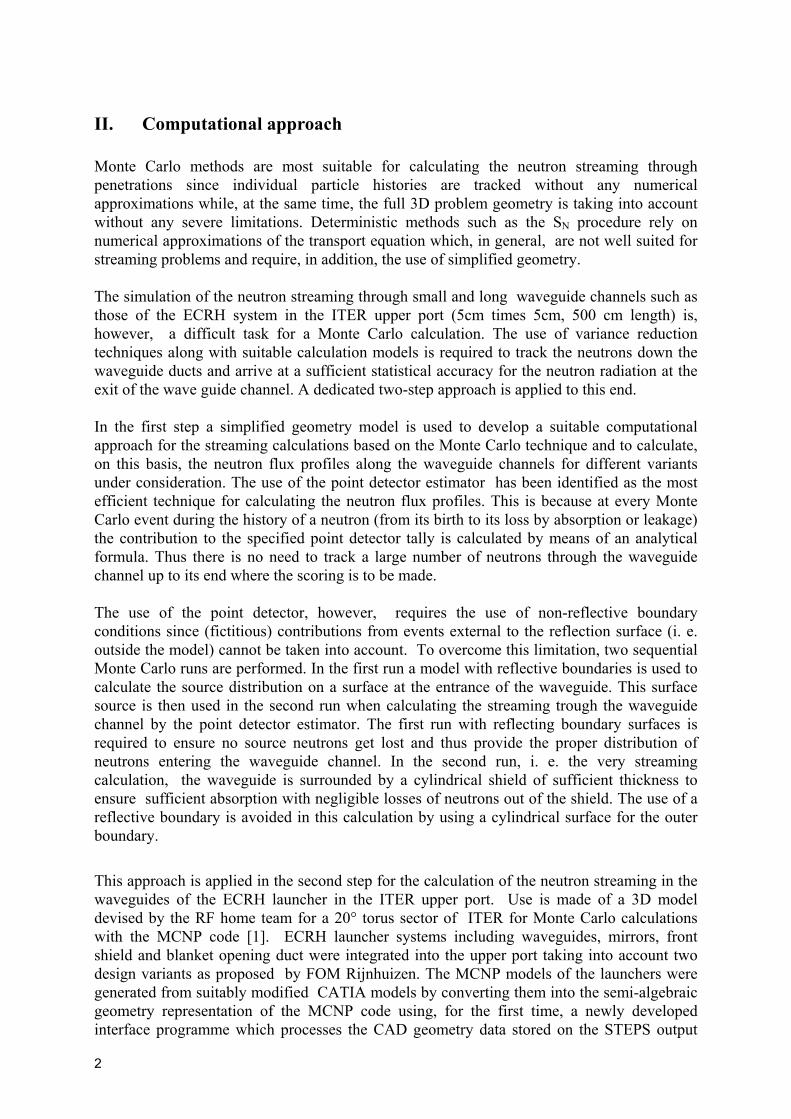
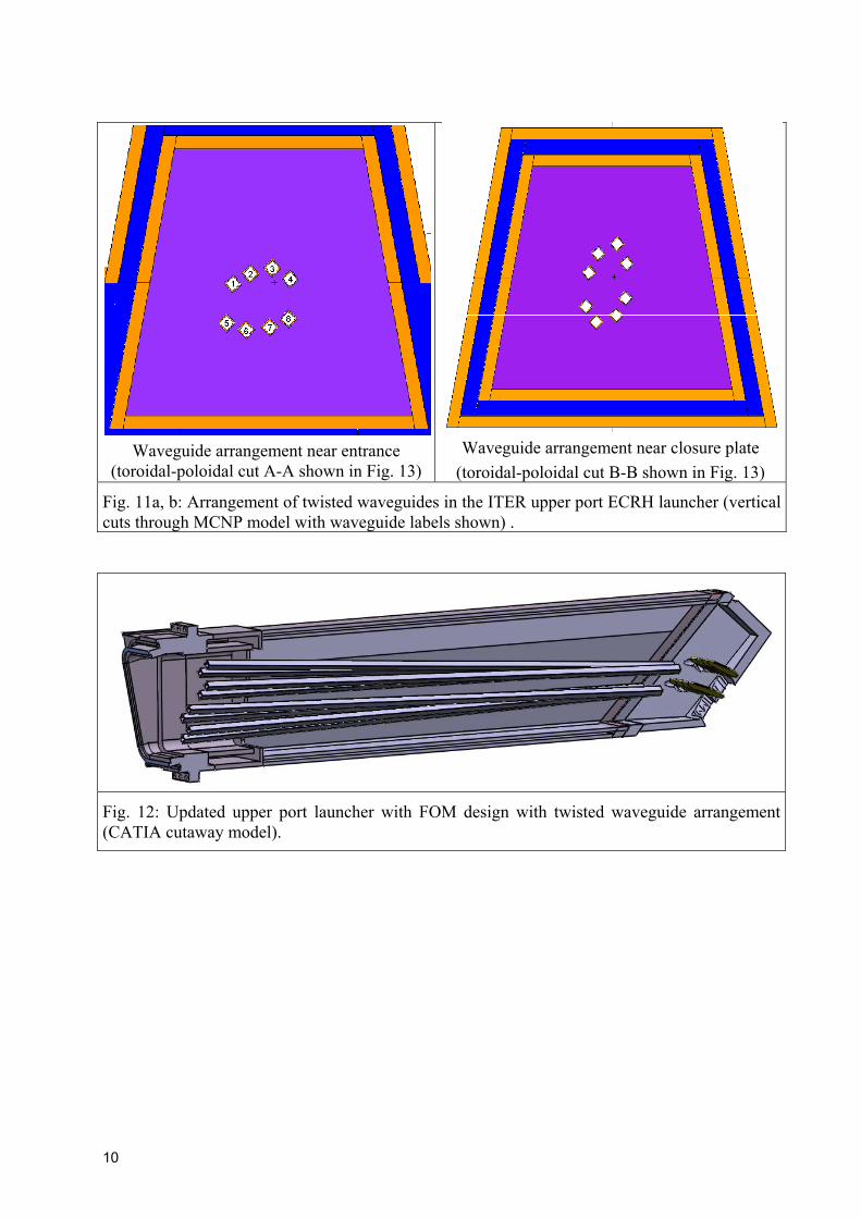
IV.B. FOM launcher design with twisted waveguides A new launcher design with a twisted orientation of the waveguides was proposed by FOM to avoid interference of the waveguide pipes with the launcher structural walls. The waveguides are oriented ins such a way that a 2x4 horizontal arrangement at the entrance transforms into a vertical 4x2 arrangement at the closure plate, see Fig. 11 a, b [3]. This launcher design was integrated into the recently updated ITER Upper Port Plug model, see Fig. 12. By making use of the CAD interface programme, the new launcher model was then converted through several iterations into a MCNP model and, eventually, integrated into the upper port of the 3D torus sector model A vertical cross-section of the MCNP model in the upper port section is shown in Fig. 13. Note that the waveguide entrance is more recessed from the plasma as compared to the 2x4 horizontal design while at the same time the front shield opening is increased. As all of the waveguides have different spatial orientiations (which may result in different attenuation profiles), neutron streaming calculations were performed for all eight waveguide ducts. Table I presents the resulting fast neutron flux densities at the entrance and the exit of the waveguides along with the attenuation factors. Fig. 14 shows the profiles for the waveguides label C1, 4, C6 and C8.
0 100 200 300 400 5001,0x108
1,0x10⁹
1,0x10¹⁰
1,0x10¹¹
1,0x10¹²
1,0x10¹³
1,0x10¹⁴
ECRH upper port launcher FOM design March 2003
Fast
neu
tron
flux
dens
ity [c
m-2*s
-1]
Distance from waveguide exit [cm]
C1 C2 C3
10
Waveguide arrangement near entrance (toroidal-poloidal cut A-A shown in Fig. 13)
Waveguide arrangement near closure plate (toroidal-poloidal cut B-B shown in Fig. 13)
Fig. 11a, b: Arrangement of twisted waveguides in the ITER upper port ECRH launcher (vertical cuts through MCNP model with waveguide labels shown) .
Fig. 12: Updated upper port launcher with FOM design with twisted waveguide arrangement (CATIA cutaway model).
11
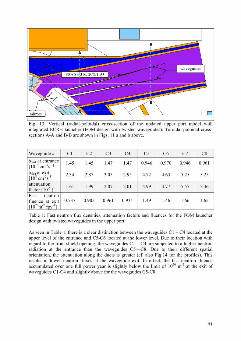
Fig. 13: Vertical (radial-poloidal) cross-section of the updated upper port model with integrated ECRH launcher (FOM design with twisted waveguides). Toroidal-poloidal cross-sections A-A and B-B are shown in Figs. 11 a and b above. Waveguide # C1 C2 C3 C4 C5 C6 C7 C8 φfast at entrance [1013 cm-2s-1]
1.45 1.45 1.47 1.47 0.946 0.970 0.946 0.961
φfast at exit [108 cm-2s-1]
2.34 2.87 3.05 2.95 4.72 4.63 5.25 5.25
attenuation factor [10-5 ]
1.61 1.99 2.07 2.01 4.99 4.77 5.55 5.46
Fast neutron fluence at exit [1020m-2 fpy-1]
0.737 0.905 0.961 0.931 1.49 1.46 1.66 1.65
Table 1: Fast neutron flux densities, attenuation factors and fluences for the FOM launcher design with twisted waveguides in the upper port. As seen in Table 1, there is a clear distinction between the waveguides C1 – C4 located at the upper level of the entrance and C5-C6 located at the lower level. Due to their location with regard to the front shield opening, the waveguides C1 – C4 are subjected to a higher neutron radiation at the entrance than the waveguides C5—C8. Due to their different spatial orientation, the attenuation along the ducts is greater (cf. also Fig.14 for the profiles). This results in lower neutron fluxes at the waveguide exit. In effect, the fast neutron fluence accumulated over one full power year is slightly below the limit of 1020 m-2 at the exit of waveguides C1-C4 and slightly above for the waveguides C5-C8.
80% SS-316, 20% H2O
mirrors
waveguides
A
A
B
B

12
Fig. 14: Fast (E> 0.1 MeV) neutron flux profiles along waveguides in updated ITER upper port with FOM twisted waveguide launcher design. V. Conclusions A suitable computational approach based on the Monte Carlo technique has been established for calculating the streaming of neutrons in small and long ducts such as the waveguides of the ECRH launcher in the ITER upper port. Two sequential Monte Carlo calculations are required, a first one to provide the neutron source distribution at the waveguide entrance and a second one to calculate the streaming effect in the waveguide ducts by applying the Monte Carlo point detector estimator for the neutron flux calculation. This approach can be applied with any complex 3D geometrical configuration such as the ITER torus sector model with the ECRH launcher integrated in the upper port. By using Monte Carlo geometry models of the launcher generated from the underlying CAD models through a newly developed interface programme, any uncertainties and deficiencies of the 3D geometry models are avoided. Based on the current design of the ECRH upper port launcher by FOM Rijnhuizen assuming straight waveguides, the fast neutron fluence accumulated over one full power year was shown to be at a level around1020 m-2. Thus the design limit for a CVD diamond window to limit the degradation of the thermal conductivity can be met with straight waveguides in the upper ECRH port. This applies even more when taking into account a real operation scenario since ITER will achieve no more than half a full power year over its scheduled lifetime of 20 years. With regard to the radiation load to the CVD window, the use of dog-leg type or double bend waveguides thus can be avoided in the ITER upper port.
0 100 200 300 400 5001,0x108
1,0x10⁹
1,0x10¹⁰
1,0x10¹¹
1,0x10¹²
1,0x10¹³
Updated ECRH upper port launcher FOM design twisted waveguides
Fast
neu
tron
flux
dens
ity [c
m-2*s
-1]
Distance from waveguide entrance [cm]
C1 C4 C6 C8

13
Further analyses are required for the lay-out and optimisation of the shielding of the launcher to ensure that the required radiation dose limits inside the port can be met as well.
Acknowledgement This work has been performed in the framework of the nuclear fusion programme of Forschungszentrum Karlsruhe and is supported by the European Union within the European Fusion Technology Programme
References
[1] J.F. Briesmeister (Ed.), MCNP - A General Monte Carlo N-Particle Transport Code, Version 4C, Los Alamos National Laboratory, Report LA-13709-M, April 2000.
[2] H. Iida, V. Khripunov, L. Petrizzi, ITER Nuclear Analysis Report, G 73 DDD 2 01-06-06 W0.1, June 2001, pp. 92-94.
[3] B.S.Q. Elzendoorn et al, Design description of the remote-steering ECW upper-port launcher for ITER, this conference.