Embed Size (px)
Citation preview

Proceedings of the 1st Thermal and Fluid Engineering Summer Conference, TFESC August 9-12, 2015, New York City, USA
TFESC-12869
*Corresponding Author: [email protected]
1
ANALYSIS OF DISSOLVED GAS IN THE APPLICATION OF
LIQUID PISTON GAS COMPRESSION Longzhong Huang1*, Terrence W. Simon1, Perry Y. Li1, Edward J. Hummelt2
1 Mechanical Engineering Department, University of Minnesota,
111 Church St. S.E., Minneapolis MN, 55455 2 Eaton Corporation, W126 N7250 Flint Drive, Menomonee Falls, WI, 53051
ABSTRACT
Liquid piston compression technology is being explored as a way to achieve high-pressure gas compression in
Compressed Air Energy Storage (CAES) systems. When combined with a porous medium, a liquid piston
compressor is able to provide near-isothermal compression, and high efficiency. However, the gas being
compressed can dissolve into the liquid resulting in loss of compressed gas output. Also, the dissolved gas in the
liquid lines can cause aeration that causes damage to pumps and valves. To understand this gas transport
phenomenon in the liquid and to evaluate the total amount of gas dissolved, a numerical model was developed.
Dispersion due to the porous medium is found to be the dominant mode of mass transfer. The dispersion
coefficient is calculated based on an experimental correlation that is given in terms of flow velocity, porous
medium geometry and molecular diffusion coefficient. The numerical model is used to investigate a case study
in which a water liquid piston is used for air compression. The amount of dissolved gas under various conditions
is calculated, such as gas concentration of the inlet flow to the compressor and discharge pressure to the storage
tank at the end of compression. The effects of different types of liquids are also quantified by applying in the
model the different solubility values of gases in liquids.
KEY WORDS: Liquid piston, Dissolved gas, Porous media, Dispersion, Mass transfer
1. INTRODUCTION
Liquid piston compression has been proposed for various gas compression applications, one of which is the
compressor/expander in a high pressure compressed energy storage system [1, 2]. A liquid piston
compressor/expander utilizes a column of liquid to compress and subsequently expand the gas above it [3]
Compared to a traditional reciprocating solid piston, the liquid piston is able to eliminate gas leakage and
sliding friction. In addition, a porous medium can be put inside the compression chamber that the liquid can
also pass through. The solid porous medium, with its significant increase in surface area, is able to absorb
heat energy from the gas in real time improving the efficiency of the compression process. Reference [1]
found that the liquid piston compressor consumed 19% less energy than the reciprocating piston compressor
in the application of air compression with a pressure ratio of 9.5:1 and a cycle frequency of 20 Hz [3]. Using
this concept, an energy storage system for offshore wind turbines was designed [4-6]. The wind energy is
used to drive the liquid piston to compress air so that the energy is stored in the compressed air. This system
is more flexible and the efficiency is higher than a traditional wind power plant. Different types of porous media, such as metal foams and interrupted plates were investigated with liquid piston flow using CFD
methods [7-11] and experimentally [4-6]. It was found that the porous medium is effective in absorbing heat
from the compressed gas and makes the compression a nearly isothermal process. In all these studies, the
focus has been on compression efficiency and heat transfer. To our knowledge, no one has investigated the
mass transfer that also occurs within the compression chamber during the compression process.
Although conceptually simple, the interfaces between liquid and gas allows for gas sorption and
desorption to occur during the compression and intake stroke, respectively. The overall effect is to decrease
the total mass of gas that is delivered by the machine, thus decreasing compression efficiency. Residual
dissolved gas in the liquid can also cause aeration problems as it goes through the rest of the hydraulic

TFESC-12869
2
system. Thus, it is important to understand mass transfer of dissolved gas in the liquid and to predict the gas
solution and dissolution in the liquid under liquid piston compression. However, the local flow is complex
due to the existence of a porous medium. The complex flow generates considerable mixing, which enhances
mass transfer. This mixing is called dispersion and is a common element in chemical engineering systems.
Cussler et al. [12] discussed the dispersion concept and the factors that affect it in fluid systems. Dispersion
rate is strongly dependent on the flow velocity. At low flow velocities, the magnitude of dispersion is similar
to diffusion. At high flow velocities, the dispersion coefficient is almost linear to flow velocity. The type of
porous medium is another important factor that affects the dispersion coefficient. Different types of porous
media will generate different flow fields and, thus, affect the mixing differently. Delgado [13] summarized
the topic for packed beds, which are widely used in chemical engineering. They developed empirical
correlations for dispersion coefficients based on experimental data. These correlations can be used to predict
dispersion for many applications. In this study, a computation model is established to understand the mass
transfer processes of gas solution in a liquid when the liquid is compressing the gas. The model results can
be used in the design of a degassing system, if one is needed.
2. NUMERICAL MODEL
In the application of a liquid piston for energy storage, the liquid is pumped into a compression chamber
containing a porous medium and a charge of gas. As the liquid enters, the gas is compressed heating the gas
and simultaneously transferring most of the compression heat into the porous medium. Thus, the energy
stored inside the gas mainly as mechanical pressure energy. At the end of the compression stroke, an exhaust
valve opens allowing the gas to be transferred from the compression chamber to a storage tank. After the gas
is expelled, exhaust and intake valves close and open, respectively, while the liquid is withdrawn from the
compression chamber. This allows a fresh charge of gas to enter the compression chamber readying it for the
next compression cycle.
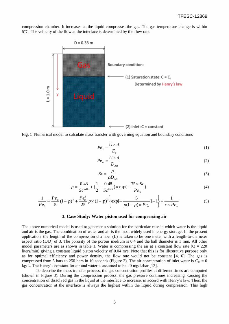
A numerical model is developed to calculate the mass transfer that occurs during the compression
and intake process (Figure 1). The compression chamber is a cylinder with a length of one meter and
diameter of 0.33 meter that is filled with small spheres of 1.0 mm diameter stacked to a porosity of 0.4. The
porous medium is effective in absorbing the thermal energy of the compressed gas during compression but
also causes pressure drop as liquid passes through it. The large pressure gradient in the axial direction of the
compression chamber allows the flow through the porous media to be modeled as one-dimensional flow.
When the liquid is compressing the gas, the gas is inclined to dissolve into the liquid.
The gas concentration in the liquid (C) changes due to dispersion and convection. Dispersion
describes the mixing and transport of gas in a liquid as it flows through a porous medium which is
proportional to the dispersion coefficient and the gradient of gas concentration. The speed of the velocity
determines the rate of the convection term. The governing equation that describes the mass transfer process
is thus given by:
y
CU
y
CE
t
Cz
2
2
The dispersion coefficient Ez (PeL = U×d/ Ez) is calculated based on an experimental correlation which is a
function of flow velocity, ball diameter, diffusion coefficient, and Schmidt number [13] (equations (1~5)).
The dimensionless Peclet number (PeL) is used to describe the ratio of convection to dispersion. It is used to
obtain the correlation. The diffusion coefficient (DAB) of gas through a liquid is calculated based on the
Wilke and Chang equation [14]. For boundary conditions, the concentration of the interface between gas and
liquid is calculated from Henry’s law [12], which states that the concentration is proportional to the gas
pressure and a constant (Ci (y= interface) = P×kH). Henry’s constant, kH, which is dependent only on
temperature, describes the solubility of gas in the liquid. The source of the liquid is assumed to be at constant
concentration Cin. Thus, the boundary condition at the inlet concentration of the compression chamber is (C =
Cin). For initial conditions, the initial gas pressure and temperature are given. The pressure and temperature
of the gas is calculated by ideal gas law. The initial gas concentration in the liquid is also given. The gas
pressure used to calculate the gas concentration at the interface is the same as the gas pressure inside the
TFESC-12869
3
compression chamber. It increases as the liquid compresses the gas. The gas temperature change is within
5°C. The velocity of the flow at the interface is determined by the flow rate.
Fig. 1 Numerical model to calculate mass transfer with governing equation and boundary conditions
z
LE
dUPe
(1)
AB
mD
dUPe
(2)
ABD
Sc
(3)
)75
exp()48.0
2
1(
48.015.015.0
mPe
Sc
ScScp
(4)
mm
mm
L PePepppp
Pep
Pe
Pe
11]
)1(
5exp[)1(
25)1(
5
1 32
2 (5)
3. Case Study: Water piston used for compressing air
The above numerical model is used to generate a solution for the particular case in which water is the liquid
and air is the gas. The combination of water and air is the most widely used in energy storage. In the present
application, the length of the compression chamber (L) is taken to be one meter with a length-to-diameter aspect ratio (L/D) of 3. The porosity of the porous medium is 0.4 and the ball diameter is 1 mm. All other
model parameters are as shown in table 1. Water is compressing the air at a constant flow rate (Q = 220
liters/min) giving a constant liquid piston velocity of 0.04 m/s. Note that this is for illustrative purpose only
as for optimal efficiency and power density, the flow rate would not be constant [4, 6]. The gas is
compressed from 5 bars to 250 bars in 10 seconds (Figure 2). The air concentration of inlet water is Cin = 0
kg/L. The Henry’s constant for air and water is assumed to be 20 mg/L/bar [12].
To describe the mass transfer process, the gas concentration profiles at different times are computed
(shown in Figure 3). During the compression process, the gas pressure continues increasing, causing the
concentration of dissolved gas in the liquid at the interface to increase, in accord with Henry’s law. Thus, the
gas concentration at the interface is always the highest within the liquid during compression. This high

TFESC-12869
4
concentration drives gas into the liquid due to the concentration difference and the penetration rate is
determined by the dispersion coefficient. A steep concentration curve near the interface is clearly seen in the
figure due to the rapid increase of interface concentration associated with the rapidly rising gas pressure
(Figure 2). After the gas reaches its highest pressure (250 bars), the discharge valve opens and the gas is
expelled from the compression chamber to a storage tank with minimal pressure drop. At the end of the
discharge process, the exhaust valve closes and the intake valve opens to draw in a fresh charge of air for the
next compression cycle. During the intake process (t >10s), the gas pressure decreases rapidly as the liquid
recedes, which causes the gas concentration at the interface to drop to a low level (5 bar). However, some
distance into the liquid, the gas concentration remains high. Here, the liquid is supersaturated and the gas
may nucleate to form bubbles. In this simulation, all the nucleated gas is assumed to remain entrained in the
liquid (buoyancy forces ineffective). The bubble concentration (Figure 4) is calculated by subtracting the
saturation concentration (equal to the gas concentration at the gas to liquid interface) from the local gas
concentration. As the intake stroke progresses, it is observed that the gas disperses over the length of the
liquid column with a concentration distribution that is lognormal in appearance (Figure 3). In addition, gas
continues to exit the liquid at the gas to liquid interface decreasing the total amount of gas still contained
within the liquid.
The amount of gas sorbed by the liquid is important because it affects the volumetric efficiency of
the machine. The total dissolved gas is calculated by integrating the concentration profile through the liquid
volume. Figure 5 shows the increase of total mass of air in the water for one compression. At the end of the
compression cycle, 0.9 gram of air is dissolved into the water, which is about 0.45% of the total initial air
mass. During the intake process, about 0.65 gram of the air comes out of the liquid through the interface and
re-enters into the compression chamber. So 0.25 gram of the air is in the liquid at the end of the full stroke. It
is worth noting that this residual gas raises the concentration of the gas in the liquid in the next compression
cycle, and unless removed, can reduce volumetric compression efficiency and cause cavitation within the
machine.
Table 1 Air conditions and Parameters of water piston to compress air

TFESC-12869
5
Fig. 2 Pressure of air inside the compression chamber

TFESC-12869
6
Fig. 3 Air concentration in the water at different times.
Fig. 4 Bubble concentration in the water at different times.

TFESC-12869
7
Fig. 5 Amount of Air in water at different times.
4. Various effects on dissolved gas in the liquid
To further characterize the dissolved gas in the liquid piston, effects such as solubility of gas in the liquid
and the compression chamber geometry are considered.
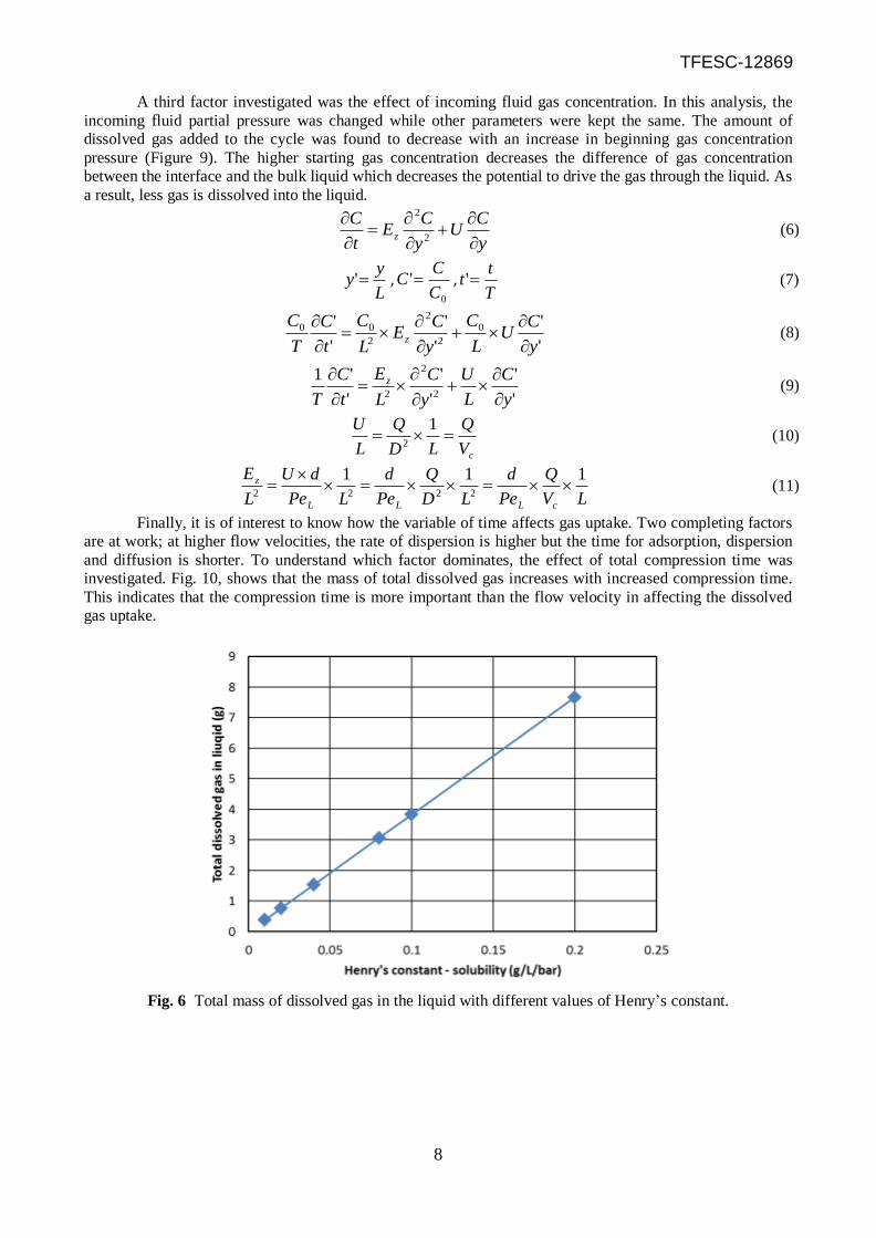
First, the solubility of gas in the liquid, as described by Henry’s law, was investigated. High
solubility indicates high saturated gas concentration in the liquid for a given pressure. The chemical makeup
of the gas and liquid and their temperature are major factors leading to different solubilities of the gas in the
liquid. Henry’s law provides the equation to describe solubility, C = P×kH, in which C is gas concentration in
the liquid, P is the gas partial pressure adjacent to the liquid interface and kH is Henry’s constant. Figure 6
shows the total dissolved gas in the system for different values of Henry’s constant. In this study, Henry’s
constant is the only parameter that is changed. It is clear that, in this case, since Cin = 0 [kg/L], the total
dissolved gas is linear with Henry’s constant. The partial pressure of gas in the liquid is another important
parameter in the application since it will determine the possibility of cavitation in pumps, lines and valves
that may be in the system. It is found that the partial pressure of gas in the liquid is constant, regardless of the
value of Henry’s constant. To confirm this result, the governing equations for gas concentration (C) in the
liquid as well as boundary conditions were rewritten as an explicit function of partial pressure (P) (Figure 7).
The result shows the governing equation to be independent of Henry’s constant. From this we conclude that
for the same compression pressure profile, the partial pressure of gas in the liquid will also be the same.
Another factor that may affect the amount of dissolved gas in the liquid is the geometry of the
compression chamber. Table 2 shows five different compression chambers with different length-to-diameter
aspect ratios, but with the same total volume. It was found that total amount of dissolved gas decreases with
an increase of length-to-diameter ratio (L/D). To explain this behavior, the original governing equation
(equation (6)) is normalized by length, time and concentration (y’ = y/L, C’ = C/C0, t’ = t/T). The final
normalized equation is expressed as equation (9) in which y’, C’, t, are normalized position, concentration,
time and L, C0, T are length of compression chamber, inlet concentration, and total compression time. The
coefficient on the convection term, U/L, can be transformed to the ratio of flow rate to total volume of
compression chamber (Q/Vc) in equation (10). The flow rate and total volume are kept the same in the five
cases, which indicates that the convection term is not affected by L/D. The coefficient for the dispersion term,
Ez/L2, is transformed to the product of d/PeL, Q/Vc, and 1/L in equation (11). The ball diameter (d) is kept the
same and the Peclet number (PeL) is also the same for the five cases, which indicates that the values of d/PeL
are the same. Thus, the coefficient of dispersion term decreases with increases of length of the compression
chamber. As the convection term doesn’t change, the total mass transfer rate decreases with an increase of
length of the compression chamber. We conclude that the total dissolved gas content decreases with
increases of length-to-diameter ratio (L/D) of the compression chamber.
TFESC-12869
8
A third factor investigated was the effect of incoming fluid gas concentration. In this analysis, the
incoming fluid partial pressure was changed while other parameters were kept the same. The amount of
dissolved gas added to the cycle was found to decrease with an increase in beginning gas concentration
pressure (Figure 9). The higher starting gas concentration decreases the difference of gas concentration
between the interface and the bulk liquid which decreases the potential to drive the gas through the liquid. As
a result, less gas is dissolved into the liquid.
y
CU
y
CE
t
Cz
2
2
(6)
L
yy ' ,
0
'C
CC ,
T
tt ' (7)
'
'
'
'
'
' 0
2
2
2
00
y
CU
L
C
y
CE
L
C
t
C
T
Cz
(8)
'
'
'
'
'
'12
2
2 y
C
L
U
y
C
L
E
t
C
T
z
(9)
cV
Q
LD
Q
L
U
12
(10)
LV
Q
Pe
d
LD
Q
Pe
d
LPe
dU
L
E
cLLL
z 1112222
(11)
Finally, it is of interest to know how the variable of time affects gas uptake. Two completing factors
are at work; at higher flow velocities, the rate of dispersion is higher but the time for adsorption, dispersion
and diffusion is shorter. To understand which factor dominates, the effect of total compression time was
investigated. Fig. 10, shows that the mass of total dissolved gas increases with increased compression time.
This indicates that the compression time is more important than the flow velocity in affecting the dissolved
gas uptake.
Fig. 6 Total mass of dissolved gas in the liquid with different values of Henry’s constant.

TFESC-12869
9
Fig. 7 Governing equations and boundary conditions in the form of partial pressure (P) of gas in liquid
Table 2 Compression chamber with different geometries
Fig. 8 Total mass of dissolved gas in the liquid with different values of L/D.

TFESC-12869
10
Fig. 9 Additional dissolved gas in the liquid with different values of inlet partial pressure.
Fig. 10 Total mass of dissolved gas in the liquid with different values of total compression time.
6. CONCLUSIONS
The uptake and transport of dissolved gas in the application of a liquid piston compression machine was
investigated. A numerical model was developed that describes the transient mass transfer of the gas over a
full compression cycle. The change in gas concentration was found to be governed by dispersion and
convection effects with the dispersion coefficient calculated using published empirical correlations. The
numerical model successfully calculates the transport of gas within the liquid and was used to obtain a
solution for the specific case of water compressing air. For the model problem, the rate of rise in gas
concentration was found to be steep due to the rapid increase of gas pressure inside compression chamber

TFESC-12869
11
and the total gas uptake was calculated to be less than 0.45% of the starting air mass. Using the numerical
model, the effects of solubility of gas in the liquid and the effects of the compression chamber geometry on
dissolved gas content were investigated. The results can be used to guide a choice of fluid and compression
chamber. The total dissolved gas was found to be linear to the solubility of the gas in liquid as described by
Henry’s law. Moreover, the gases partial pressure profile was determined to be independent of the gases
solubility, a result that was validated by analysing the governing equations. The effects of compression
chamber geometry were also evaluated. An increase in the length-to-diameter ratio (L/D) was found to
decrease the gas dissolved in the liquid and the normalized governing equations were used to analyse this
L/D effect. It is found that increasing L/D decreases dispersion and, thus, decreases dissolved gas content in
the liquid. Finally, the rate of gas uptake was found to decrease with higher gas concentration in the
incoming liquid and gas uptake was found to increase with increasing compression time. This result suggests
that the time for dispersion and diffusion dominates over the effect flow velocity has on the dispersion
coefficient. Overall, the developed model was found to be a useful tool for analysing the uptake and transfer
of absorbed gas within a liquid piston compression machine.
Acknowledgment: The information, data, or work presented herein was funded in part by the Advanced
Research Projects Agency-Energy (ARPA-E), U.S. Department of Energy, under Award Number DE-
AR0000258.
Disclaimer: The information, data, or work presented herein was funded in part by an agency of the United
States Government. Neither the United States Government nor any agency thereof, nor any of their
employees, makes any warranty, express or implied, or assumes any legal liability or responsibility for the
accuracy, completeness, or usefulness of any information, apparatus, product, or process disclosed, or
represents that its use would not infringe privately owned rights. Reference herein to any specific
commercial product, process, or service by trade name, trademark, manufacturer, or otherwise does not
necessarily constitute or imply its endorsement, recommendation, or favoring by the United States
Government or any agency thereof. The views and opinions of authors expressed herein do not necessarily
state or reflect those of the United States Government or any agency thereof.
NOMENCLATURE
PeL: Peclet number for dispersion
Pem: Peclet number for diffusion
Sc: Schmidt number
DAB
: diffusion coefficient (m2/s)
Ez: dispersion coefficient (m2/s)
U: fluid velocity (m/s)
Vc: total volume of compression chamber (L)
d: ball diameter (m)
τ: tortuosity factor (0.7 for sphere)
L: Length of compression chamber (m)
C: Gas concentration (kg/L)
D: Diameter of compression chamber (m)
kH: Henry’s constant (kg/L/bar)
P: Pressure (Pa)
Q: liquid flow rate (m3/s)
ρ: density (kg/m3) μ: viscosity (Pa·S)
Ci: Saturated gas concentration (kg/L)
REFERENCES
[1] Li, P. Y., Loth, E., Simon, T. W., Van de Ven, J. D., and Crane, S. E., “Compressed air energy storage for offshore wind
turbines,” in Proc. International Fluid Power Exhibition (IFPE), Las Vegas, USA, 2011.
[2] Saadat, M. and Li, P. Y., “Modeling and control of an open accumulator compressed air energy storage (CAES) system for
wind turbines", Applied Energy. Vol. 137, pp. 603-616, Jan 2015
[3] Van de Ven, J. D. and Li, P. Y., “Liquid piston gas compression,” Applied Energy, pp. 1-10, (2008).
[4] Yan, B., Wieberdink, J., Shirazi, F., Li, P. Y., Simon, T. W. and Van de Ven, J.D., “Experimental study of heat transfer
enhancement in a liquid piston compressor/expander using porous media inserts”, (In review)
[5] Wieberdink, J., “Increasing efficiency and power density of a liquid piston air compressor / expander with porous media heat
transfer elements”, M.S. Thesis, Department of Mechanical Engineering, University of Minnesota, Dec. 2014.

TFESC-12869
12
[6] Yan, B., “Compression/expansion within a cylindrical chamber: application of a liquid piston and various porous inserts” M.S.
Thesis, Department of Mechanical Engineering, University of Minnesota, 2013
[7] Zhang, C., Yan, B., Wierberdink, Li, P. Y., Van de Ven, J. D., Loth, E. and Simon, T. W., “Thermal analysis of a compressor
for application to compressed air energy storage”, Applied Thermal Energy, Vol. 73:2, pp.1402-1411, Dec 2014.
[8] Saadat, M. and Li, P. Y., “Modeling and control of a novel compressed air energy storage system for offshore wind turbine,” in
Proc. American Control Conference, pp. 3032-3037, Montreal, Canada, 2012.
[9] Zhang, C, Saadat, M, Li, P. Y. and Simon T. Heat transfer in a long, thin tube section of an air compressor: an empirical
correlation from CFD and a thermodynamic modeling. In: Proceedings of the 2012 ASME International Mechanical
Engineering Congress, Houston, TX, no. #86673; 2012.
[10] Zhang, C., Shirazi, F. A., Yan, B., Simon, T. W., Li, P. Y. and Van De Ven, J., “Design of an interrupted-plate heat exchanger
used in a liquid-piston compression chamber for compressed air energy storage,” Proc. of the ASME 2013 Summer Heat
Transfer Conference, Minneapolis, Minnesota, (July 2013). Conference Proceeding
[11] Zhang, C., Wieberdink, J. H., Shirazi, A. F., Yan, B., Simon, T. W. and Li, P. Y., “Numerical investigation of metal-foam
filled liquid piston compressor using a two-energy equation formulation based on experimentally validated models,
Proceedings of the ASME 2013 International Mechanical Engineering Congress and Exposition, (2013). Conference
Proceeding
[12] Cussler, E., Diffusion: Mass Transfer in Fluid Systems, Cambridge, (1997).
[13] Delgado J. M. P. Q., “A critical review of dispersion in packed beds,” Heat Mass Transfer, 42, pp. 279-310, (2006).
[14] Wilke C. R. and Chang P., “Correlation of diffusion coefficients in dilute solutions,” A.I.Ch.E. Journal, pp. 264-270, (1955).