Embed Size (px)
Citation preview

* Corresponding author. +1 540 231 1776; [email protected]
ANALYSIS OF A LATENT THERMOCLINE ENERGY STORAGE SYSTEM FOR CONCENTRATING SOLAR POWER PLANTS
Karthik Nithyanandam1, Ranga Pitchumani1* and Anoop Mathur2 1Advanced Materials and Technologies Laboratory, Department of Mechanical Engineering, Virginia Tech, Blacksburg,
Virginia 24061, USA; 2 Terrafore Inc., 100 South 5
th Street, Suite 1900, Minneapolis 55402, USA.
ABSTRACT: The primary purpose of a thermal energy storage system in
a concentrating solar power (CSP) plant is to extend the opera-
tion of plant at times when energy from the sun is not ade-
quate by dispatching its stored energy. Storing sun’s energy in
the form of latent thermal energy of a phase change material
(PCM) is desirable due to its high energy storage density
which translates to less amount of salt required for a given
storage capacity. The objective of this paper is to analyze the
dynamic behavior of a packed bed encapsulated PCM energy
storage subjected to partial charging and discharging cycles,
and constraints on charge and discharge temperatures as en-
countered in a CSP plant operation. A transient, numerical
analysis of a molten salt, single tank latent thermocline energy
storage system (LTES) is performed for repeated charging and
discharging cycles to investigate its dynamic response. The
influence of the design configuration and operating parameters
on the dynamic storage and delivery performance of the sys-
tem is analyzed to identify configurations that lead to higher
utilization. This study provides important guidelines for de-
signing a storage tank with encapsulated PCM for a CSP plant
operation.
INTRODUCTION Concentrating solar power (CSP) generation is becoming
attractive for meeting current and future energy needs. A key
requirement to make this energy option competitive is through
the use of a thermal energy storage unit. Storing energy for
future use allows the power plant to operate continuously dur-
ing periods of intermittent sun, reduces the mismatch between
the energy supply and demand by providing load leveling and
helps to conserve energy by improving the reliability and per-
formance of energy system Thermal energy can be stored as
either sensible or latent heat. Most of the thermal energy stor-
age systems in operation are based on sensible heat storage.
However, storing heat in the form of latent heat of fusion of
phase change material (PCM) in addition to sensible heat sig-
nificantly increases the energy density. For example, the ener-
gy required to melt one kilogram of sodium nitrate (latent
heat) is 75 times higher compared to the energy required to
raise the temperature of one kilogram of sodium nitrate by 1K
(sensible heat). Thus thermal storage systems using PCM as
storage medium have the advantage of being compact in size.
However, a major technology barrier that is limiting the use of
latent thermal energy of PCM is the higher thermal resistance
provided by its intrinsically low thermal conductivity. This
requires large heat transfer surface area of interaction between
the working fluid and PCM in order to maintain high heat
rates, typically required in power plants. Several efforts [1–6]
were made to improve the heat transfer rates. However, a
promising approach is to increase the heat transfer area by
incorporating the PCM mixture in small capsules using suita-
ble shell materials. For example, PCM stored in capsule diam-
eters of 10 mm possess surface area of more than 600 square
meters per cubic meter of capsules. Research to find suitable
materials and process to encapsulate high temperature PCM
mixtures is underway [7]. In this paper, we discuss the effec-
tiveness of using latent heat when PCM melts and solidifies
inside small capsules by direct contact with a heat transfer
fluid.
A single-tank thermocline storage system packed with
spherical capsules containing PCM is considered in the pre-
sent work. The working of latent thermocline energy storage
(LTES) system in a CSP involves the exchange of heat be-
tween the HTF and the packed bed of spherical PCM capsules.
The operation of a LTES constitutes the charging and dis-
charging processes. During charging, hot HTF from the solar
power tower enters the LTES from the top and heat transfer
between the HTF and PCM takes place thus effecting the
melting of PCM at a constant temperature. As hot HTF enters
the tank, the existing cold fluid in the tank is forced from the
bottom to return to the solar field. During discharging, cold
fluid is pumped from the bottom of the LTES resulting in the
solidification of the PCM within the capsules and the hot fluid
exiting the top of the tank is directed to the power block for
steam generation. Buoyancy forces ensure stable thermal strat-
ification of hot and cold fluids within the tank. The charging
process takes place during the day when solar energy is avail-
able while discharging is effected whenever the sun is not
available or when there is a peak demand in electricity. The
charging and discharging process combined is referred to as
one cycle and repeated cycles subjected to partial charging and
Proceedings of the ASME 2012 6th International Conference on Energy Sustainability ES2012
July 23-26, 2012, San Diego, CA, USA
ES2012-91389
1 Copyright © 2012 by ASME

discharging process may limit the rate of phase change of
PCM and decrease the utilization of the tank. This paper fo-
cuses on investigating the dynamic thermal behavior of LTES
to develop guidelines for the design of latent thermocline
thermal energy storage tank for a CSP plant.
Numerous works on the numerical modeling of sensible
heat storage in packed beds are found in the literature [8–15].
As a pioneering work, Schumann et al. [9] presented the first
numerical study on modeling of the packed bed which is wide-
ly adopted in the literature. The model enables prediction of
the temporal and axial variation of the HTF and filler bed
temperatures in a thermocline tank. Van Lew et al. [14] adopt-
ed the Schumann model to analyze the performance of ther-
mocline energy storage system embedded with rocks as filler
material. The efficiency of solving the governing equations
using the method of characteristics was discussed. Ismail and
Henriquez [16] presented a mathematical model for predicting
the thermal performance of cylindrical storage tank containing
spherical capsules filled with water as PCM. The model was
used to investigate the influence of the working fluid inlet
temperature, flow rate of the working fluid and material of the
spherical capsule of 77 mm diameter during the solidification
process. Felix Regin et al. [17] and Singh et al. [18] presented
a brief review of the works performed in the thermocline stor-
age system till date. Felix Regin et al. [19] also reported the
modeling of thermocline energy storage system with embed-
ded PCM capsules. The modeling follows the Schumann’s
equation except that the dependent variable for energy equa-
tion of filler bed is enthalpy and not temperature. The re-
sistance developed during the solidification phase change pro-
cess was accounted for by a decrease in the heat transfer coef-
ficient between the HTF and the filler bed. Hänchen et al. [20]
employed the Schumann’s equation to discuss the effects of
particle diameter, bed dimensions, fluid flow rate and the solid
filler material on the dynamic performance of thermocline
storage system. Uniform charging and discharging times were
considered and the efficiency of the system as a function of
cycles was monitored. Wu and Fang [21] analyzed the dis-
charging characteristics of a solar heat storage system with a
packed bed of spherical capsules filled with myristic acid as
PCM. The influence of HTF mass flow rate, inlet temperature
and the porosity of packed bed were studied.
Although several articles on the thermocline tank packed
with sensible filler materials is reported, relatively few works
on the performance of a latent thermocline energy storage
system is found in the literature. To the author’s knowledge, a
thorough modeling of solidification and melting process of
encapsulated PCM in a thermocline energy storage system and
a comprehensive study of the dynamic performance of the
system subjected to constraints dictated by the power plant
operation is lacking in the literature. To this end, the objective
of the present study is to develop a detailed model of a ther-
mocline storage system containing spherical capsules filled
with PCM and investigate the influence of the design and op-
erating parameters on the dynamic performance of the system
to identify configurations that lead to higher system utiliza-
tion. A further contribution is that while most of the studies in
the literature pertain to low temperature LTES, the present
study focuses on a high temperature LTES system which can
be installed in CSP plants.
MATHEMATICAL MODEL
Figure 1a illustrates a schematic of a thermocline storage
tank of height Ht and radius Rt packed with spherical capsules.
For the sake of clarity in illustration, the capsules are schemat-
ically shown to be arranged in an ordered fashion. However,
in reality, as the PCM capsules are piled up pressing each oth-
er from the top to bottom the packing scheme may vary and
the porosity of the packed bed for a fixed diameter of spherical
capsules can range from 0.26–0.476 [22]. The red colored
arrows indicate the direction of hot HTF during charging
while the blue colored arrows indicate the direction of cold
HTF as it enters the storage system during discharging. The
inner radius of the capsules filled with PCM (yellow shade) is
represented by Rc, while the thickness of the capsule wall is
denoted by b as depicted in Fig. 1b.
The flow of the HTF is considered incompressible. The
PCM is assumed to be homogeneous without any impurities
and isotropic such that the physical properties are independent
of direction. This assumption affects the melting (solidifica-
tion) rate of the PCM although the effect of which on micro-
encapsulated PCM as considered here would be negligible.
The outer surface of the thermocline tank is considered to be
adiabatic and a uniform radial distribution of the HTF flow is
assumed which was also confirmed from a detailed computa-
tional analysis of the system (not discussed here). Since the
Peclet number of the HTF flow in the thermocline tank is large
(Pe >> 100) the axial heat conduction in the HTF is negligible
[23]. The Biot number of the transient heat conduction in a
single PCM spherical capsule is small enough that lumped
heat capacitance method is applicable; however a transient
radial energy equation in the PCM is solved for to calculate
the spatial and temporal temperature variation and melt inter-
face location. Thermal expansion and shrinkage of PCM in the
spherical capsules is not accounted for in the present study and
the density of solid and liquid phase of the PCM is considered
to be same. Thermal conduction between the spherical PCM
capsules is neglected because of the large contact resistance.
The melting and solidification process within a PCM is mod-
eled by the enthalpy-porosity technique as introduced by
Voller et al. [24]. By this approach, the porosity in each cell is
set equal to the liquid fraction, in the cell, which takes either
the value of 1 for a fully liquid region, 0 for a solid region, or
0 < < 1 for a partially solidified region (mushy zone). Based
on the foregoing assumptions, the governing energy equations
in the axi-symmetric coordinate system (z-r) shown in Fig. 1a
for the HTF and encapsulated PCM phase are as follows:
21
,
3)(4
)1(3
2 RTRT
fT
pT
bc
Rz
fT
tR
f
mf
cf
t
fT
fc
fcRr
(1)
)(1 2
,2 r
Trk
rrt
T
Thc
p
effp
p
p
lpp
(2)
where RT1 and RT2 in Eq. (1) denote the thermal resistance
offered by radial heat conduction in the capsule wall and con-
vective heat transfer between the HTF and filler phase
2 Copyright © 2012 by ASME
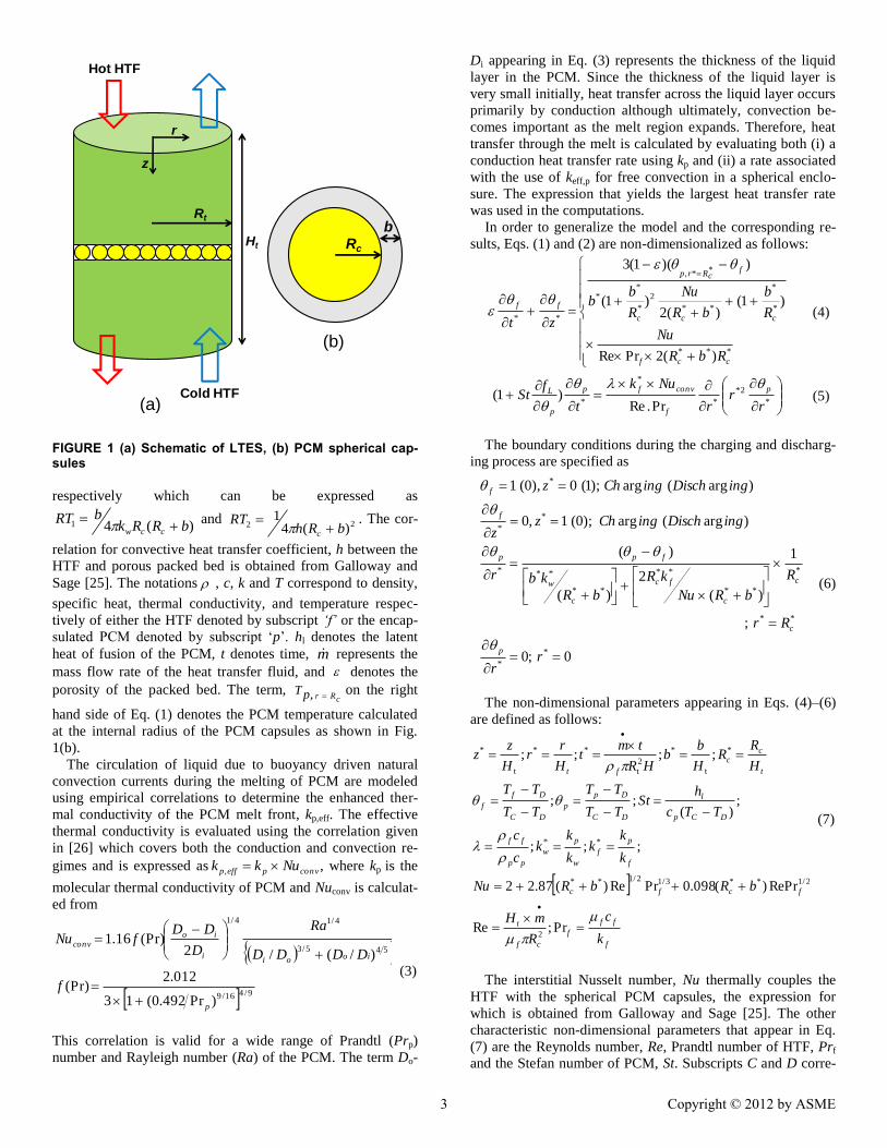
FIGURE 1 (a) Schematic of LTES, (b) PCM spherical cap-sules
respectively which can be expressed as
)(41 bRRkbRT
ccw
and 22 )(4
1bRh
RTc
. The cor-
relation for convective heat transfer coefficient, h between the
HTF and porous packed bed is obtained from Galloway and
Sage [25]. The notations , c, k and T correspond to density,
specific heat, thermal conductivity, and temperature respec-
tively of either the HTF denoted by subscript ‘f’ or the encap-
sulated PCM denoted by subscript ‘p’. hl denotes the latent
heat of fusion of the PCM, t denotes time, m represents the
mass flow rate of the heat transfer fluid, and denotes the
porosity of the packed bed. The term, cRrpT
, on the right
hand side of Eq. (1) denotes the PCM temperature calculated
at the internal radius of the PCM capsules as shown in Fig.
1(b).
The circulation of liquid due to buoyancy driven natural
convection currents during the melting of PCM are modeled
using empirical correlations to determine the enhanced ther-
mal conductivity of the PCM melt front, kp,eff. The effective
thermal conductivity is evaluated using the correlation given
in [26] which covers both the conduction and convection re-
gimes and is expressed as convpeffp Nukk , , where kp is the
molecular thermal conductivity of PCM and Nuconv is calculat-
ed from
9/416/9
45545/3
4/14/1
)Pr492.0(13
012.2(Pr)
)/(/2(Pr)16.1
p
iooii
ioconv
f
DDDD
Ra
D
DDfNu
(3)
This correlation is valid for a wide range of Prandtl (Prp)
number and Rayleigh number (Ra) of the PCM. The term Do-
Di appearing in Eq. (3) represents the thickness of the liquid
layer in the PCM. Since the thickness of the liquid layer is
very small initially, heat transfer across the liquid layer occurs
primarily by conduction although ultimately, convection be-
comes important as the melt region expands. Therefore, heat
transfer through the melt is calculated by evaluating both (i) a
conduction heat transfer rate using kp and (ii) a rate associated
with the use of keff,p for free convection in a spherical enclo-
sure. The expression that yields the largest heat transfer rate
was used in the computations.
In order to generalize the model and the corresponding re-
sults, Eqs. (1) and (2) are non-dimensionalized as follows:
***
*
*
**
2
*
**
**,
**
)(2PrRe
)1()(2
)1(
))(1(3
ccf
ccc
fcRrp
ff
RbR
Nu
R
b
bR
Nu
R
bb
zt
(4)
*
2*
*
*
* Pr.Re)1(
rr
r
Nuk
t
fSt
p
f
convfp
p
L
(5)
The boundary conditions during the charging and discharg-
ing process are specified as
The non-dimensional parameters appearing in Eqs. (4)–(6)
are defined as follows:
f
ff
f
cf
t
fcfc
f
p
f
w
p
w
pp
ff
DCp
l
DC
Dp
p
DC
Df
f
t
cc
ft
k
c
R
mH
bRbRNu
k
kk
k
kk
c
c
TTc
hSt
TT
TT
TT
TT
H
RR
H
bb
HR
tmt
H
rr
H
zz
Pr;Re
;RePr)(098.0PrRe)(87.22
;;;
;)(
;;
;;;;
2
2/1**3/12/1**
**
*
t
*
2
t
**
t
*
(7)
The interstitial Nusselt number, Nu thermally couples the
HTF with the spherical PCM capsules, the expression for
which is obtained from Galloway and Sage [25]. The other
characteristic non-dimensional parameters that appear in Eq.
(7) are the Reynolds number, Re, Prandtl number of HTF, Prf
and the Stefan number of PCM, St. Subscripts C and D corre-
Rc
b
Hot HTF
Cold HTF
z
r
Rt
Ht
0;0
;
1
)(
2
)(
)(
)arg (arg);0 (1,0
)arg (arg);1 (0),0 (1
*
*
**
*
**
**
**
***
*
*
*
rr
Rr
R
bRNu
kR
bR
kbr
ingDischingChzz
ingDischingChz
p
c
c
c
fc
c
w
fpp
f
f
(6)
(a)
(b)
3 Copyright © 2012 by ASME
spond to the hot inlet HTF temperature during charging and
the cold inlet HTF temperature during discharging, respective-
ly.
The numerical simulations started from a charge process
assuming that the tank is completely discharged resulting in
the following initial conditions for the HTF and filler phase
The complete set of governing equations is discretized us-
ing the finite volume approach and the melting/solidification
of the PCM is modeled using the fixed-grid enthalpy approach
as presented by Voller et al. [24]. In order to accurately pre-
dict the liquid fraction in the fixed grid enthalpy-based proce-
dure, the liquid fraction in each computational cell, in con-
junction with the temperature predicted by the equation for
encapsulated PCM, should be updated at each iteration within
a time step. In the present case, the enthalpy iterative updating
scheme of the liquid fraction takes the following form for a
pure PCM, which melts at constant temperature:
)(1,0
1 ni
nipp
i
ini
ni Fc
a
a
(9)
In the above equation, ai is the coefficient of i for the ra-
dial nodal point i in the discretized equation of the energy
equation for PCM, n is the iteration number, is a relaxation
factor, which is set to 0.01 for the present case, and F-1
is the
inverse of latent heat function which takes the value of Tm for
a pure substance. The coupled system of governing equations
is solved by implicit method and the solution is advanced in
time using Runge-Kutta time stepping scheme. After careful
examination of the grid refinement process, a grid interval size
of 0.003 is chosen in the axial direction within the thermocline
tank and the encapsulated PCM within the spherical capsules
is discretized into 10 uniform zones in the radial direction. The
non-dimensional time step chosen for the study was
0001.0* t .
The numerical model allowed for modeling all the physical
heat transfer processes that occur within the system namely,
the convective heat transfer between the HTF and the filler
phase, the radial thermal conduction in the wall, the conduc-
tion in the solid PCM, conduction and natural convection
within the liquid PCM. The outputs from the model comprise
the transient axial variation of temperature in the HTF, the
transient radial variation of temperature and the melt fraction
contour of PCM within the capsule at any axial location. The
transient total energy available within the system ( *TQ ) is
composed of sensible energy ( *SQ ) and latent energy ( *
LQ )
components calculated as the summation of energy stored in
all the PCM capsules and the HTF which can be determined
from the following expressions
p
j
q
ic
iip
fS
R
zVzQ
1 1
*
3*
*
,**)1(
(10a)
p
j
q
ic
iiL
R
zVStQ
1 1
*
3*
** )1(
(10b)
where i represents the radial node at any axial location, j. p
and q denotes the total number of discretized finite volumes in
the axial direction of the tank and radial direction of the cap-
sules respectively. The performance metrics characterizing the
behavior of the system analyzed in the present work are the
cyclic total utilization (*
max,
*
, TDTT QQU ) and latent utiliza-
tion (*
max,
*
, LDLT QQU ) where *,DTQ ( *
,DLQ ) denote the total
(latent) energy discharged in a cycle which is obtained by sub-
tracting the total, *TQ (latent, *
LQ ) energy available within the
system, at the end of the discharging process form the total
energy available within the system at the end of the charging
process of the corresponding cycle. *max,TQ and *
max,LQ repre-
sent the maximum total and latent storage capacity of the tank
which can be easily obtained from Eqs. (10a) and (10b) as-
suming 1, pf and 1 .
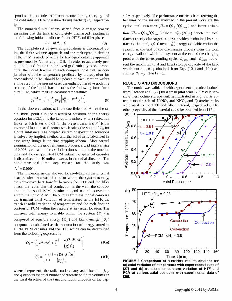
RESULTS AND DISCUSSIONS The model was validated with experimental results obtained
from Pacheco et al. [27] for a small pilot scale, 2.3 MW h sen-
sible thermocline storage tank as illustrated in Fig. 2a. A eu-
tectic molten salt of NaNO3 and KNO3 and Quartzite rocks
were used as the HTF and filler material, respectively. The
other properties of the material could be obtained from [27].
FIGURE 2 Comparison of numerical results obtained for (a) axial variation of temperature with experimental data of [27] and (b) transient temperature variation of HTF and PCM at various axial positions with experimental data of [28].
0.0
0.2
0.4
0.6
0.8
1.0
0.0 0.2 0.4 0.6 0.8 1.0
Avera
ge T
em
pe
ratu
re, avg
Axial Position, z*
t = 0.0 h
t = 0.5 h
t = 1.0 h
t = 1.5 h
t = 2.0 h
30
40
50
60
70
80
0 20 40 60 80 100 120 140 160
Te
mp
era
ture
, T
[oC
]
Time, t [min]
HTF, z/HT = 0.25
Conduction +Convection
Conduction
PCM, z/HT = 0.5
Figure 2
(a)
(b)
0;0 pf (8)
4 Copyright © 2012 by ASME

The experimental results obtained for the transient discharging
profile of the HTF temperature for every 30 minutes up to a
maximum of 2 hours are denoted by markers. The initial con-
dition corresponds to the final charging state of the first cycle,
which was also carried out for 2 hours. To analyze the perfor-
mance of sensible thermocline system with the developed
model for latent thermocline energy storage system, the non-
dimensional PCM melting temperature, m is set to a value
greater than 1 and the Stefan number of the filler material, St
is set to 0. The numerically simulated axial temperature distri-
butions of the average temperature between the HTF and filler
particle for the various time instants as reported in [27] are
represented by the colored lines in Fig. 2a. Within the experi-
mental uncertainty, the agreement between experimental data
and numerical results is quite satisfactory. Fig. 2b shows the
comparison of the numerical results obtained from the present
model with experimental data obtained from Nallusamy et al.
[28] for a packed bed thermocline system filled with spherical
capsules of diameter 55 mm. The capsules were filled with
paraffin wax which melts at 60 °C and water was selected as
the HTF. It is observed that prediction of melting rate of the
PCM with convection assisted model leads to a sound agree-
ment with the experimental data than a conduction only mod-
el. Neglecting the free convection effects within the PCM pre-
dicts a slower melting rate which is not in accordance with the
obtained experimental data. Hence it is important to account
for the buoyancy driven natural convection currents which
ensues during the charging process by suitably varying the
effective thermal conductivity of the PCM as discussed in the
previous section. Acceptable agreement with experimental
results ensures the validity of the model and the parametric
studies conducted using the model is discussed in the reminder
of this section.
The operating and design parameter considered in the pre-
sent study are the Reynolds number, Re and non-dimensional
capsule radii, *
cR respectively. The default case pertains to
; 0005.0* cR
; 6000Re
;105 8* b
;25.0 Ste
; 125.0m
;5Pr f
;1
;1* wk
1* pk . The Reynolds
number and the capsule radius have a significant effect on the
pressure drop across the tank which dictates the parasitic
pump power and cost. Hence the non-dimensional pump work
during discharge is also monitored in the present study to
study the effects of Reynolds number and the non-dimensional
capsule radius ( *
cR ) on the pump work. The non-dimensional
pump work during discharge can be obtained from, 2*** Pr).(ReDp tpW where the non-dimensional pressure
drop can be expressed as, mRpp t2* and the pressure
drop p for flow through a porous obtained from Ergun’s
expression [29].
Figure 3a shows the axial temperature distribution of the
HTF, f at the end of charging and discharging process of the
latent thermocline storage system corresponding to fourth cy-
cle. Initially at t* = 0, the tank is in a completely discharged
state as established by Eq. (8). The numerical computation
started from a charge process with the hot HTF entering the
top of the tank at z* = 0. Charging was continued until the
temperature of the cold HTF which exits the tank at z* = 1 and
goes to the solar field reaches a certain maximum temperature
as dictated by the solar power tower operation. For a given
solar heat flux, as the inlet temperature of the HTF into the
solar power tower increases, the outlet temperature of the HTF
from the tower which is directed towards the power block also
increases. In order to maintain the CSP plant design outlet
temperature, correspondingly the HTF mass flow rate has to
be decreased which will affect the overall efficiency of the
plant operation in generating the required power output. The
charging cut-off temperature, referred to as C from this point
on, is thus established by the above mentioned constraint.
After the charge process, the temperature distribution in the
tank is taken as the initial condition for the subsequent dis-
charge process. During discharge, cold HTF is directed into
the tank bottom at z* = 1 and the exiting hot HTF collected
from the top of the tank is pumped to the power block for
Rankine cycle superheated steam generation. Similar to charg-
ing, the discharge process is stopped after the temperature
exiting the top of the tank reaches a certain minimum cut-off
temperature, D below which the Rankine cycle efficiency
decreases significantly. The combined charge and discharge
process is referred to as one cycle. In the present study, C
and D were selected to be 0.15 and 0.85 respectively repre-
sentative of restrictions imposed on 100 MWe CSP plant op-
eration [30]. Subsequent cycles were carried out until the
FIGURE 3 (a) Axial variations of the charge and discharge temperature profile of the HTF and (b) transient variation of the HTF charge and discharge exit temperature
0.0
0.2
0.4
0.6
0.8
1.0
0.0 0.2 0.4 0.6 0.8 1.0
HT
F T
em
pe
ratu
re, f
Axial Position, z*
t* = 0.0
Total Utilization, UT
Charge
Discharge
0.0
0.2
0.4
0.6
0.8
1.0
0.0 0.3 0.6 0.9 1.2
HT
F E
xit T
em
pera
ture
, f,e
Time, t*
Discharge
Charge
(a)
(b)
5 Copyright © 2012 by ASME

HTF axial temperature distribution within the tank reached a
cyclic quasi-steady state independent of the initial condition. It
was found that, with the current conditions the solution
reached cyclic steady state after four charge and discharge
cycles for the various range of parametric values considered in
the present study and the results presented pertain to the sys-
tem performance at the end of fourth cycle. The percentage of
shaded area in Fig. 3a gives a visual representation of the total
utilization, UT of the LTES system.
From Fig. 3a it can be seen that, the discharge temperature
profile at any given time can be divided into four zones: a
constant low-temperature zone ( 0f ) near the discharge
inlet, a constant high-temperature zone ( 1f ) which pre-
vails near the discharge outlet, a constant melt-temperature
zone ( mf ) and an intermediate heat exchange zone (
10 f ). In the constant low- and high-temperature zones
the molten salt and PCM capsules are in thermal equilibrium
while in the heat exchange zone energy in the form of sensible
heat is transferred from the PCM capsules to the HTF during
discharge and in the constant melt-temperature zone, energy is
transferred in the form of latent heat from the PCM to the
HTF.
The exit temperatures of the HTF during the charge and
discharge process are portrayed in Fig. 3b. The solid red col-
ored line corresponds to the exit temperature profile during the
first cycle while the dashed red colored line correspond to the
exit temperature profile established during the fourth cycle.
During the charge process, the exit temperature remains at the
high temperature after which it increases and then stays steady
at the melting temperature of the PCM until it increases to the
cut-off temperature within a short duration. Thus possessing a
PCM which melts at a temperature below the charging cut-off
temperature is seen to extend the operation of a LTES. Similar
exit temperature profile for the discharge process is represent-
ed by solid and dashed blue colored lines, albeit, the delinea-
tion between the curves is hardly discernible as a cyclic quasi-
steady state was achieved within the first two cycles for the
default design and operating conditions.
Figure 4a depicts the axial variation of melt fraction within
the encapsulated PCM in the thermocline tank at the end of the
charge and discharge process of the fourth cycle. The percent-
age of the shaded area depicts the latent utilization of the sys-
tem which is effectively the amount of PCM in the storage
tank that undergoes alternate melting and solidification during
the cyclic charge and discharge process respectively. It is seen
that during the first charge process almost all the PCM is
completely molten except for some amount of PCM near the
exit of the tank, as the HTF temperature at z* = 1 reaches the
charging cut-off temperature. During the subsequent discharge
process, only 40 % of the PCM is solidified before the tem-
perature of the HTF exiting the top of the tank at z* = 0 de-
creases from 1f to Df . This is attributed to the low
temperature difference between the HTF discharge inlet tem-
perature, D and the PCM melting temperature, m compared
to the charge process and also the slow conduction dominated
discharge mechanism. Figure 4b portrays the energy charged
and discharged by the tank as a function of the cycles. For this
particular default case, the thermocline settles into a cyclic
quasi-steady state by the end of the second cycle. The amount
FIGURE 4 (a) Axial variation of the PCM melt fraction dur-ing the charge and discharge process and (b) cyclic sen-sible and latent energy charged and discharged.
of energy charged at the first cycle is higher than the rest of
the cycles while the energy discharged by the thermocline tank
is almost the same throughout the four cycles which is in ac-
cordance with the trends observed in Figs. 3a and 4a. Thus the
performance of the thermocline tank degrades from the first
cycle and hence the performance of the tank is explored only
after a cyclic quasi-steady state is achieved.
Figure 5 portrays the effects of Reynolds number on the
Nusselt number for various non-dimensional capsule radii.
The influence of Reynolds number and the non-dimensional
capsule radius on the Nusselt number is obtained from the
empirical correlation suggested by Galloway and Sage [25]. It
is observed that both Reynolds number and capsule radius
have a pronounced effect on the Nusselt number and the heat
transfer rate between the HTF and spherical PCM capsules is
observed to be higher for larger radii capsules and higher HTF
mass flow rate, m . Also it is important to observe that the
Nusselt number levels off after a certain Reynolds number
after which increasing the HTF mass flow rate does not have a
significant impact on the heat transfer rate between the HTF
and the spherical PCM capsules. The trends reported in Fig. 5
will be referred to in the discussions pertaining to the rest of
the figures.
Figure 6a shows the axial discharge temperature profile of
the HTF at the end of the fourth cycle for various Re. It is ob-
served that with increase in Reynolds number the heat ex-
change zone expands. At the higher Reynolds number, a
0.0
0.2
0.4
0.6
0.8
1.0
0.0 0.2 0.4 0.6 0.8 1.0
Melt F
raction,
Axial Position, z*
Latent Utilization, U
L
Discharge Charge
t* = 0.0
Charge
Discharge
1 2 3 40
0.1
0.2
0.9
1.0
1.1
1.2
Cycle, i
La
ten
t Energ
y C
harg
ed
(Dis
ch
arg
ed
),
Q*L
,C (Q
*L,D
)
Sen
sib
le E
nerg
y C
ha
rged (
Dis
cha
rged
),
Q* S
,C (
Q* S
,D)
(a)
(b)
6 Copyright © 2012 by ASME

FIGURE 5 Variation of Nusselt number with Re and R*
c
longer flow distance is required for the HTF to be heated by
the PCM spherical capsules which results in a gradual temper-
ature increase and a corresponding expansion of the heat ex-
change zone. Also, the constant melt-temperature zone is ob-
served to reduce in height as the Reynolds number increases.
For instance at Re = 600000, the discharge temperature profile
depicted by the solid red colored line does not possess the
constant melt-temperature zone reflecting an inefficient ex-
traction of latent energy from the PCM. Figure 6b shows that
the charge (discharge) time decreases with increase in Reyn-
olds number. Since the heat exchange zone is at a lower tem-
perature than the higher temperature, the discharging cut-off
temperature is reached quicker for higher Re as the heat ex-
change zone expands. Consequently, the utilization and latent
utilization of the system also decreases as portrayed in Fig. 6c.
As seen in Fig. 6c, beyond a Re = 150000, the utilization and
also the latent utilization does not decrease much because of
the higher heat transfer rate between the HTF and spherical
PCM capsules concomitant with increase in Nusselt number,
Nu observed in Fig. 5. Although the non-dimensional pump
work, W*p depends on Re
2 , it is observed in Fig. 6b that the
discharge time decreases drastically with increase in Re, re-
sulting in an almost linear increase in the pump work.
Similarly, Fig. 7a presents the axial discharge temperature
profile of the HTF at the end of the fourth cycle for the various
non-dimensional capsule radii values, R*
c. Similar to the effect
of Re, it was observed that increasing R*
c results in an expan-
sion of the heat exchange zone and restricts the formation of
constant melt-temperature zone. This is attributed to the fact
that for a given height of the tank, increasing the capsule radi-
us, results in an increased resistance to the conduction domi-
nated PCM solidification which occurs during discharge pro-
cess. Also, the surface contact area between the HTF and cap-
sules per unit tank volume decreases with larger R*
c, which
limits the heat exchange rate and leads to a poor thermocline
performance. Figure 7b presents the effect of the non-
dimensional capsule radius on the charge and discharge time
of the thermocline tank. It is observed that the charge and dis-
charge time of the thermocline tank almost levels off beyond
004.0* cR . This is because of the fact that with increase in
FIGURE 6 Variation of (a) axial HTF discharge temperature profile (b) charge (discharge) time and pump work, and (c) total and latent utilization with Reynolds number
R*
c, the heat exchange rate decrease and the conduction re-
sistance within the PCM increases which results in a negligi-
ble utilization of the latent energy in the capsules. Thus only a
smaller portion of the PCM adjoining the capsule wall alone is
solidified and the thermocline typically operates only in the
sensible energy regime as seen by the absence of constant
melt-temperature zone in the violet and red colored lines in
Fig. 7a. This results in faster discharge time as the HTF tem-
perature exiting the tank reaches the cut-off temperature faster.
Further it is observed from Fig. 7c that between 00013.0* cR
and 004.0* cR the utilization decreases quite drastically with
increase in R*c, due to the increase in the conduction resistance
0
300
600
900
1200
1500
0 150 300 450 600
Nusse
lt N
um
ber,
Nu
Reynolds Number, Re [x 103]
R*
c = 0.0080
R*
c = 0.0040R
*
c = 0.001
R*
c = 0.0005
R*
c = 0.0003
R*
c = 0.0001
0
20
40
60
80
100
0 10 20 30 40
Nusse
lt N
um
ber,
Nu
HTF Prandtl Number, Prf
R*
c = 8.000
R*
c = 4.000
R*
c = 1.000
R*
c = 0.500
R*
c = 0.250
R*
c = 0.125
Figure 2
(a) (b)
Re = 60
Re = 600
Re = 6000
Re = 60000
Re = 300000
Re = 600000
0.0
0.2
0.4
0.6
0.8
1.0
0.0 0.2 0.4 0.6 0.8 1.0
HT
F T
em
pera
ture
, f
Axial Position, z*
0.4
0.6
0.8
1.0
1.2
0
100
200
300
400
Charge
Discharge
Cha
rge
(D
isch
arg
e)
Tim
e,
t* C (
t* D)
Pu
mp
Wo
rk, W
*p [x 1
01
5]
0
25
50
75
0 150 300 450 600
Latent
Total
Reynolds Number, Re [x 103]
To
tal (L
ate
nt)
Utiliz
atio
n,
UT (
UL)
[%]
(a)
(b)
(c)
7 Copyright © 2012 by ASME

in spite of the increase in Nusselt number (Fig. 5). On observ-
ing the utilization of the thermocline storage system, it can be
seen that larger diameter capsules possess a lower utilization
(Fig. 7c) and hence smaller diameter capsules are preferred for
stable dynamic operation of the system. But, with decrease in
R*
c, the pressure drop across the bed increases, which, coupled
with a longer discharge time for R*
c below 0.00041, leads to a
drastic increase in the pump work (Fig. 7b). Based on the
competing effects between the pump work and latent utiliza-
tion with smaller R*c, it can be observed from Figs. 7b and c
that the non-dimensional radius of the capsule should not be
smaller than 00041.0* cR , which
FIGURE 7 Variation of (a) axial HTF discharge temperature profile (b) charge (discharge) time and pump work, and (c) total and latent utilization with R*
c
is selected by carefully monitoring the change in slope of the
pump work curve. For the purpose of illustration, if the height
of the tank is considered to be Ht = 14 m as commonly em-
ployed in a 3000 MWh-th power plant [30], the capsule radius
should be approximately 5.77 mm to realize simultaneous
benefits of high utilization and low pump work.
Figure 8 portrays the total utilization of the LTES system
calculated for different Re and different non-dimensional cap-
sule radius, *
cR . The range of the Reynolds number and the
non-dimensional capsule radius values chosen for this plot
corresponds to the practical design of a LTES system for CSP
plant. It is clear from Fig. 8 that utilization decreases with
increase in Re and*
cR . At higher Reynolds number, the mass
flow rate is higher. Hence the existing hot fluid in the tank is
discharged faster, after which due to insufficient residence
time of the cold inlet HTF within the tank, heat exchange be-
tween the HTF and spherical PCM capsules do not take place
efficiently, resulting in a faster decay of the HTF discharge
temperature and contributing to low system utilization. With
increase in capsule radius, the thermal conduction resistance
within the PCM increases resulting in a decrease in the latent
utilization and hence the total system utilization also decreases
with increase in R*c. This highlights the important effects of
the Reynolds number and capsule radius, R*c on the design of
a latent thermocline storage system. Thus for a given HTF
Reynolds number established by the discharge power require-
ments of the CSP plant, and for an assumed height of the tank,
Fig. 8 can be used to determine the total utilization of the
LTES for various capsule radii.
FIGURE 8 Utilization of a LTES at different Re and R
*c
R*
c = 0.00013 R
*
c = 0.00025
R*
c = 0.00050
R*
c = 0.00100
R*
c = 0.00400
R*
c = 0.00800
0.0
0.2
0.4
0.6
0.8
1.0
0.0 0.2 0.4 0.6 0.8 1.0
HT
F T
em
pera
ture
, f
Axial Position, z*
0.0
0.3
0.6
0.9
1.2
1.5
0
5
10
15
20
25
Charge
Discharge
Cha
rge
(D
isch
arg
e)
Tim
e,
t* C (
t* D)
Pu
mp
Wo
rk, W
*p [x 1
01
5]
0
25
50
75
0 2 4 6 8
Latent
Total
Capsule Radius, R*
c [x 10
-3]
To
tal (L
ate
nt)
Utiliz
atio
n,
UT (
UL)
[%]
(a)
(b)
(c)
0
20
40
60
80
0 2 4 6 8
To
tal U
tiliz
ation,
UT [%
]
Capsule Radius, R*
c [x 10
-3]
Re = 60
Re = 600
Re = 3000
Re = 6000Re = 30000
0
20
40
60
80
0 2 4 6 8
To
tal U
tiliz
ation,
UT [%
]
Capsule Radius, R*
c [x 10
-3]
= 0.5
= 2.0= 1.0
8 Copyright © 2012 by ASME
CONCLUSIONS A thermocline model accounting for axial variation of tem-
perature in the HTF and radial temperature variation in the
PCM at any axial position is solved and the effects of various
non-dimensional variables on the dynamic performance of the
thermocline storage system are analyzed. Important results
pertaining to the analysis above can be summarized as fol-
lows: Smaller radii capsules yield higher total and latent utili-
zation of the latent thermocline storage system. But on the
other hand, the pressure drop increases as capsule radius de-
creases which results in a higher pump work and cost. Thus a
minimum R*c exists, that trades off between the competing
effects of the increasing pump work and total utilization with
decrease in R*c. Monitoring the change in slope of the pump
work curve, a minimum bound on the value of non-
dimensional capsule radii is established which is calculated to
be 00041.0* cR . Extrapolating the value for a 14 m tall tank,
commonly used in CSP plants, the corresponding capsule ra-
dius amounts to 5.77 mm. Higher Reynolds number and con-
sequently higher mass flow rate also leads to decrease in the
utilization of the system due to expansion of the heat exchange
zone. Based on the parametric studies, an informative design
plot characterizing the utilization of the system as a function
of both Re and R*c is illustrated. A preliminary calculation of
the exergy efficiency, defined as the ratio of exergy recovered
by the HTF during discharging to the total exergy content of
the HTF at the inlet of the thermocline during charging for the
default design and operating parametric values yielded 66.17
%. A detailed exergy analysis and optimization of a cascaded
latent thermocline storage tank will be presented in a future
work.
ACKNOWLEDGMENTS This work was supported by a grant from the U.S. Depart-
ment of Energy under Award Number DE-EE0003589. Their
support is gratefully acknowledged.
NOMENCLATURE b capsule wall thickness [m]
c specific heat [J/kg-K]
h convective heat transfer coefficient [W/m2-K]
hl latent heat of fusion of PCM [J/kg]
H height [m]
k thermal conductivity [W/m-K]
˙ m mass flow rate [kg/s]
Nu Nusselt number
Pe electrical power output [MWe]
Pr Prandtl number
Pth thermal power output [MW-th]
Q energy [MJ]
R radius [m]
Re Reynolds number
t time [s]
T temperature [K]
Tm melting temperature [K]
Subscripts and Superscripts
c capsule
C charging
D discharging
f heat transfer fluid
L latent
p phase change material
S sensible
t tank
T total
eff effective
Greek Symbols
porosity of the packed bed
dynamic viscosity
density
melt fraction
REFERENCES [1] LeFrois, R. T., Mathur, A. K., 1982, “Active Heat Ex-
changer Evaluation for Latent Heat Thermal Energy
Storage Systems,” New York : The American Society
of Mechanical Engineers, 82-HT-7.
[2] “Heat Transfer and Latent Heat Storage in Inorganic
Molten Salts for Concentrating Solar Power Plants,”
Department Of Energy, Terrafore, Inc., U.S. DOE Con-
tract: DE-FG36-08GO18148
[3] Nithyanandam, K., Pitchumani, R., 2011, “Analysis
and Optimization of a Latent Thermal Energy Storage
System with Embedded Heat Pipes,” Int. J. Heat and
Mass Transfer, 54, pp. 4596–4610.
[4] Nithyanandam, K., Pitchumani, R., 2010, “Numerical
Modeling of a Latent Heat Thermal Energy Storage
System with Integral Heat Pipes," Proceedings of the
ASME International Mechanical Engineering Congress
and Exposition, Paper No. IMECE2010-38682, Van-
couver, British Columbia, Canada, 8 pp.
[5] Nithyanandam, K., Pitchumani, R., 2012, “Computa-
tional Studies on a Latent Thermal Energy Storage
System with Integral Heat Pipes for Concentrating So-
lar Power,” Applied Energy, In Review.
[6] Nithyanandam, K., Pitchumani R., 2011, “Analysis of
latent heat thermal energy storage system with integral
heat pipes under steady state and dynamic conditions, ”
5th International Conference on Energy Sustainability,
Paper No. ESFuelCell2011-54501, Washington, DC,
USA, 10 pp.
[7] “Using Encapsulated Phase Change Material in Ther-
mal Storage for Baseload Concentrating Solar Power
Plants,” Terrafore Inc., U.S. DOE Contract: DE-
EE0003589
[8] Beasley, D. E., Clark, J. A., 1984, “Transient response
of a packed bed for thermal energy storage,” Int. J.
Heat Mass Transfer, 27, pp. 1659–1669.
[9] Schumann, T. E. W., 1929, “Heat transfer: A liquid
flowing through a porous prism,” J. Franklin Inst., 208,
pp. 405–416.
[10] Shitzer, A., Levy, M., 1983, “Transient behavior of a
rock-bed thermal storage system subjected to variable
inlet air temperature: Analysis and Experimentation,”
ASME J. Sol. Energy Eng., 105, pp. 200–206.
[11] McMahan, A. C., 2006, “Design and optimization of
organic rankine cycle solar-thermal power plants,” MS
9 Copyright © 2012 by ASME

thesis, University of Wisconsin-Madison, Wisconsin.
[12] Kolb, G. J., Hassani, V., 2006, “Performance analysis
of thermocline energy storage proposed for the 1 MW
Saguaro solar trough plant,” ASME Conf. Proc., 1.
[13] Yang, Z., Garimella, S. V., 2010, “Thermal analysis of
solar thermal energy storage in a molten-salt thermo-
cline,” Solar Energy, 84, pp. 974–985.
[14] Van Lew, J. T., Li, P., Chan, C. L., Karaki, W., Ste-
phens, J., 2011, “Analysis of heat storage and delivery
of a thermocline tank having solid filler material,” J.
Sol. Energy Engineering, 133, pp. 021003-1–10.
[15] Yang, Z. Garimella, S. V., 2011, “Molten-salt thermal
energy storage in thermoclines under different envi-
ronmental boundary conditions,” App. Energy, 87, pp.
3322–3399.
[16] Ismail, K. A. R., Henriquez, J. R., 1999, “Numerical
and experimental study of spherical capsules packed
bed latent heat storage system,” App. Thermal Eng., 19,
pp. 757–788.
[17] Felix Regin, A., Solanki, S. C., Saini, J. S., 2008, “Heat
transfer characteristics of thermal energy storage sys-
tem using PCM capsule: a review,” Renew and Sus.
Ener. Reviews, 12, pp. 2438–2458.
[18] Singh, H., Saini, R .P, Saini, J. S., 2011, “A review on
packed bed solar energy storage system,” Renew and
Sus. Ener. Reviews, 14, pp. 1059–1069.
[19] Felix Regin, A., Solanki, S. C., Saini, J. S., 2009, “An
analysis of a packed bed latent heat thermal energy
storage system using PCM capsules: Numerical inves-
tigation,” Renew. Ener., 34, pp. 1765–1773.
[20] Hänchen, M., Brückner, S., Steinfeld, A., 2011, “High-
temperature thermal storage using a packed bed of
rocks – Heat transfer analysis and experimental valida-
tion,” App. Thermal Eng., 31, pp. 1798–1806.
[21] Wang, S., Fang, G., 2011, “Dynamic performance of
solar heat storage system with packed bed using
myristic acid as phase change material,” Energy and
Buildings, 43, pp. 1091–1096.
[22] Hales, T.C., 2006, “Historical overview of the Kepler
conjecture, Discrete & Computational Geometry,” In-
ternational Journal of Mathematics and Computer Sci-
ence, 36, pp. 5–20.
[23] Kays, W. M., Crawford, M. E., Weignand, B., 2005,
Convective Heat and Mass Transfer, 4th
Ed., McGraw-
Hill, New York.
[24] Voller, V.R., Cross, M., Markatos, N.C., 1987, “An
enthalpy method for convection/diffusion phase
change,” Int. J. Numer. Methods, 24, 271–284.
[25] Galloway, T. R., Sage, B. H., 1970, “A model of the
mechanism of transport in packed, distended, and fluid-
ized beds,” Chemical Engg. Sci., 25, pp. 495–516.
[26] Yang, K. T., 1987, Natural convection in enclosures,
in: S. Kakac, R. Shah, W. Aung (Eds.), Handbook of
Single-Phase Convective Heat Transfer, Wiley, New
York.
[27] Pacheco, J. E., Showalter, S. K., Kolb, W. J., 2002,
“Development of a molten salt thermocline thermal
storage system for parabolic trough plants,” ASME J.
Sol. Energy Eng., 124 (2002) 153 – 159.
[28] Nallusamy, N., Sampath, S., Velraj, R., 2007, “Exper-
imental investigation on a combined sensible and latent
heat storage system integrated with constant/varying
(solar) heat sources,” Renewable Energy, 32, pp. 1206–
1227.
[29] Ergun, S., 1952, “Fluid Flow through Packed Col-
umns,” Chem. Eng. Prog., 48, pp. 89–94.
[30] “Solar Thermocline Storage Systems – Preliminary
design study, ” EPRI, 2010 Public Copy
10 Copyright © 2012 by ASME