Embed Size (px)
Citation preview

Revista Gaceta Técnica. Artículo de Investigación. 20(1), 7-22, enero-junio, 2019
ISSN 1856-9560 (Impreso) ISSN: 2477-9539 (Internet) Depósito Legal pp 1999907LA22 ppi201602LA4730
ANÁLISIS DE UNA PLACA BASE DE UNIÓN ENTRE
COLUMNA DE CONCRETO-COLUMNA DE ACERO
EN EL RANGO NO LINEAL
ANALYSIS OF A JOINT BASE PLATE BETWEEN
CONCRETE COLUMN-STEEL COLUMNS IN THE
NON-LINEAR RANGE
Nelson López1, Ronald Ugel2, Reyes Indira Herrera3
Recibido 13/05/2018: Aprobado: 17/09/2018
DOI: http://dx.doi.org/10.13140/RG.2.2.21271.83363
RESUMEN
En este trabajo se estudió el comportamiento en el rango lineal y no lineal de una junta (junta
viga-columna) en una probeta a escala real, constituida por una columna de concreto unida a
dos vigas de concreto mediante un vaciado monolítico; la columna de concreto se conectó a
través de una placa base de acero a una columna de acero HEA160 sometida a cargas cíclicas
durante un período de 5.000 s, obteniendo así, su curva de comportamiento histerético. Se
creó un modelo matemático en el programa ABAQUS CAE a fin de verificar que el diseño de
la junta de la probeta cumpliera con los requisitos normativos para el diseño de placas base,
en base a aplastamiento del concreto y espesor de la placa. En los pernos se verificó su
resistencia a fuerzas de corte, deformación por tracción, verificación por cono tracción en el
concreto y esfuerzos de tracción dentro de la zona agrietada, se obtuvo como resultado que la
falla se produjo por agrietamiento del concreto armado.
Palabras clave: nodo viga-columna, pseudo-estático, ABACUS CAE
1Nelson López. Ingeniero Civil. Magister Scientiarum en Mecánica Aplicada a la Construcción. Especialista en
Recursos Hidráulicos. Docente investigador en la Universidad Politécnica Salesiana. Ecuador. Correo:
[email protected]. ORCID: https://orcid.org/0000-0002-3111-7952 2Ronald Ugel. Doctor en Ingeniería Sísmica y Dinámica Estructural. Docente investigador Decanato de
Ingeniería Civil. Universidad Centroccidental Lisandro Alvarado. Venezuela. Correo: [email protected]. ORCID: https://orcid.org/0000-0003-1531-8030 3Reyes Indira Herrera. Doctora en Ingeniería Sísmica y Dinámica Estructural. Docente investigadora Decanato
de Ingeniería Civil. Universidad Centroccidental Lisandro Alvarado. Venezuela. Correo: [email protected].
ORCID: https://orcid.org/0000-0003-1639-9143
ANÁLISIS DE UNA PLACA BASE DE UNIÓN ENTRE COLUMNA DE CONCRETO-COLUMNA DE ACERO
EN EL RANGO NO LINEAL
Revista Gaceta Técnica. Artículo de Investigación. 20(1), 7-22, enero-junio, 2019
ISSN 1856-9560 (Impreso) ISSN: 2477-9539 (Internet) Depósito Legal pp 1999907LA22 ppi201602LA4730
8
Art
ícu
lo d
e In
ves
tig
ació
n
ABSTRACT
In this research the behavior of a real scale experimental joint (column-beam joint) formed by
three reinforced concrete elements, 1 column and 2 beams, attached to a structural steel
column in the upper level is studied. The object in question was subjected to the action of
cyclic loads in a single direction, in a pseudostatic test for 5000 s, in order to observe which
element of the concrete cylinders failed and which the failure mode was. A mathematical
model was created in the ABAQUS CAE software, in order to verify that the design of the
gasket of the test piece complied with the normative requirements for the design of base
plates, based on concrete crushing and thickness of the base plate. In the bolts its resistance to
shear forces, tensile deformation, and verification by tensile cone in the concrete and tensile
stress within the cracked area was verified, and it was obtained as a result that the failure was
produced by cracking of the reinforced concrete.
Keywords: beam-column joint, pseudo-static, ABAQUS CAE
1. INTRODUCTION.
In this research, a study was carried out on a real scale concrete cylinders, in a joint of a
reinforced concrete column with a structural steel one. The research is based on the behavior
of the joint under cyclic loads, in the elastic and inelastic range, focusing on the behavior of
the elements of the junction base plate between the reinforced concrete column and the
structural steel one. The base plate was designed under the seismic resistant methods and
Venezuelan regulations for the elastic range, its behavior in the inelastic range was
satisfactory from the point of view that the concrete beams and the steel column did not
present evident failures before the loads were applied, while in the concrete column there
were strong cracks a few centimeters below the beam, reaching the neutral axis of the section
of the column.
In this case, the history of displacements was applied to a concrete cylinders built in real
scale, tested by [1], composed of a column and two reinforced concrete beams, and a column
of structural steel joined to the concrete column, through a structural steel base plate, 9 mm
thick and 30 cm2 long with 4 anchor bolts 25 cm long and 12 mm diameter. The appearance
of cracking in the reinforced concrete elements could be evidenced in the test after
approximately 3900 s, and to verify the extent to which the concrete cylinders remained in the
elastic range a mathematical model was created in the ABAQUS CAE program [2], which
allowed the analysis of all the structural elements that make up the concrete cylinders under
study.
2. DEVELOPMENT
The design of joints between a steel structure and a concrete one is generally oriented to steel
beams and concrete columns, or steel beams and concrete walls, or steel columns

Nelson López, Ronald Ugel, Reyes Indira Herrera
Revista Gaceta Técnica. Artículo de Investigación. 20(1), 7-22, enero-junio, 2019
ISSN 1856-9560 (Impreso) ISSN: 2477-9539 (Internet) Depósito Legal pp 1999907LA22 ppi201602LA4730
9
Art
ícu
lo d
e In
ves
tig
ació
n
(superstructure) and concrete foundation (infrastructure). For any of these cases, these joints
have a similar configuration, as shown in Figure 1.
Figure 1. Configuration of a connection between concrete and steel. Source:[3]
2.1. Cyclic Test
This test consists in applying a load that simulates dynamic actions on the concrete cylinders,
defining for it, direction, value and frequency of load application.
Figure 2. a) A cyclic test example, b) Hysteretic behavior. Source: [1]
Figure 2 shows the graph resulting from the incremental application of a displacement
through time, translated into load applied laterally to a mixed steel-concrete frame, generating
a hysteretic behavior in the frame.
a) b)
ANÁLISIS DE UNA PLACA BASE DE UNIÓN ENTRE COLUMNA DE CONCRETO-COLUMNA DE ACERO
EN EL RANGO NO LINEAL
Revista Gaceta Técnica. Artículo de Investigación. 20(1), 7-22, enero-junio, 2019
ISSN 1856-9560 (Impreso) ISSN: 2477-9539 (Internet) Depósito Legal pp 1999907LA22 ppi201602LA4730
10
Art
ícu
lo d
e In
ves
tig
ació
n
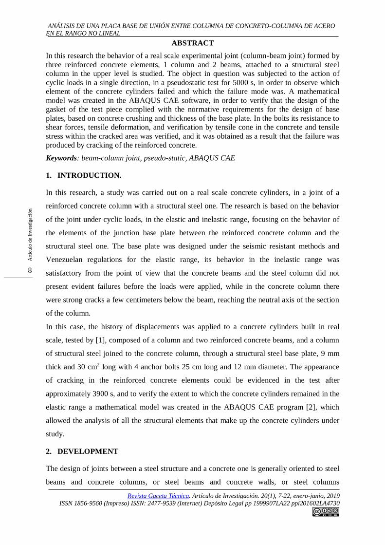
2.2. Hysteresis Model
It refers to those mathematical models capable of representing the relationship between the
resistance of an element and its deformation based on laboratory tests, with excitation of
charges named charge histories. These histories usually have a loading phase, an unloading
phase and a recharge cycle. The first curve that is generated due to these cycles is named
"primary curve" or "skeleton curve", since it is what gives an approximation of the shape of
the hysteresis curve and the resistance-deformation behavior of the structural element. The
loading phase is identified when the deformation increases in the primary curve; the
unloading phase is observed when the deformation decreases in the primary curve; the
recharging phase occurs immediately after the unloading phase, and is observed when the
deformation begins to increase its value (see Figure 3).
Figure 3. Representation of loading, unloading and recharging phases. Source: [4]
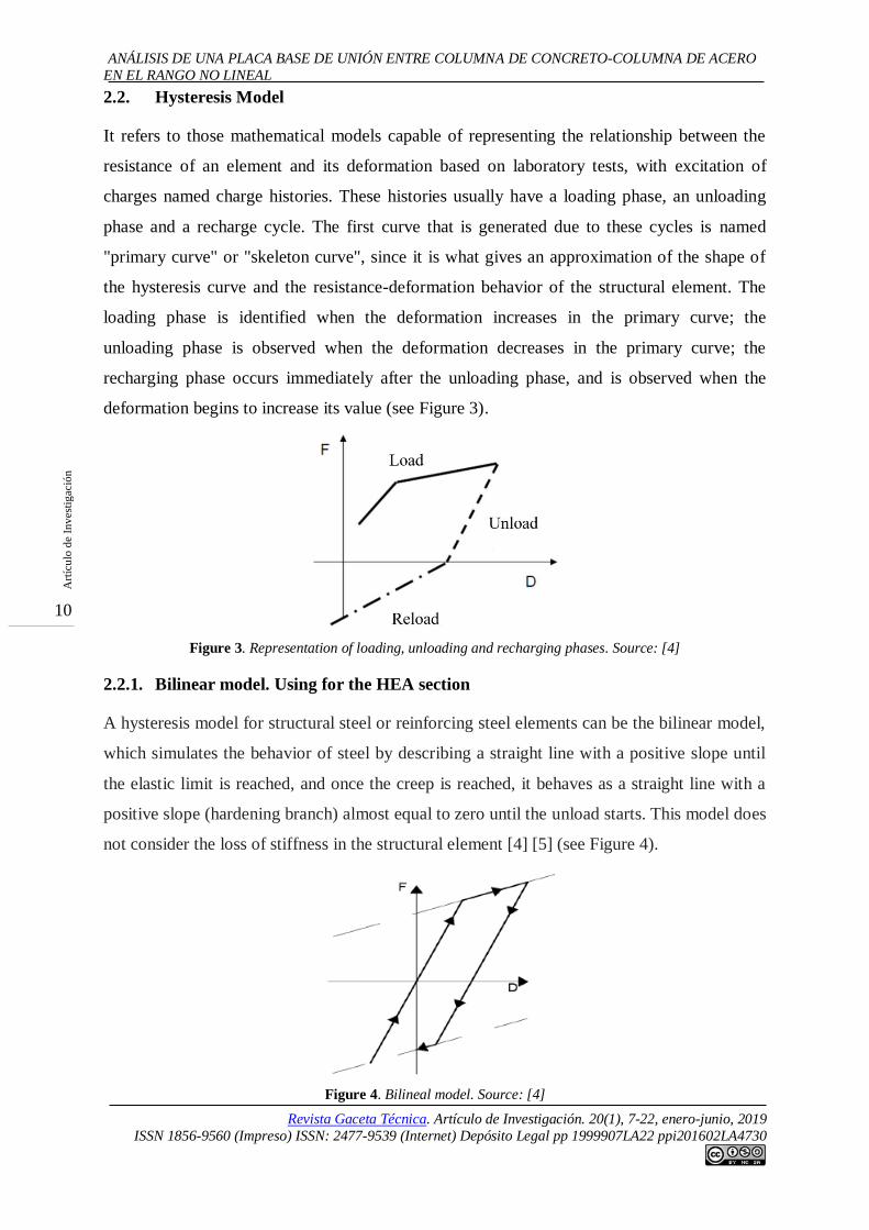
2.2.1. Bilinear model. Using for the HEA section
A hysteresis model for structural steel or reinforcing steel elements can be the bilinear model,
which simulates the behavior of steel by describing a straight line with a positive slope until
the elastic limit is reached, and once the creep is reached, it behaves as a straight line with a
positive slope (hardening branch) almost equal to zero until the unload starts. This model does
not consider the loss of stiffness in the structural element [4] [5] (see Figure 4).
Figure 4. Bilineal model. Source: [4]

Nelson López, Ronald Ugel, Reyes Indira Herrera
Revista Gaceta Técnica. Artículo de Investigación. 20(1), 7-22, enero-junio, 2019
ISSN 1856-9560 (Impreso) ISSN: 2477-9539 (Internet) Depósito Legal pp 1999907LA22 ppi201602LA4730
11
Art
ícu
lo d
e In
ves
tig
ació
n
2.2.2. Menegotto and Pinto model. Using for reinforcing steel
The Menegotto and Pinto model is one of the most used ones for the structural steel
simulation, it represents the uniaxial behavior of the material and describes the behavior of
reinforcing steel, by fibers in the cross section subject to normal stresses [6] (see Figure 5).
The non-linear equation that describes the behavior of the hysteresis curve is Equation 1.
(1)
Where:
effective stress in the loading and unloading phases
effective deformation in the loading and unloading phases
relationship between the values of the initial and final tangent stress
parameter that defines the shape of the discharge curve
Figure 5. Menegotto and Pinto model. a) First cycle, b) Subsequent. Source: [6]
2.2.3. Mander Model
The Mander model [7] is a non-linear model that represents the behavior of concrete. It was
developed for concrete elements confined by several types of transversal reinforcement, and
closely resembles the behavior of concrete especially in columns; also accepts static or
dynamic loads applied monotonically or by cycles, in sections of rectangular, square or
circular concrete (see Figure 6).
Figure 6. Mander et al model. Source: [7]
a) b)

ANÁLISIS DE UNA PLACA BASE DE UNIÓN ENTRE COLUMNA DE CONCRETO-COLUMNA DE ACERO
EN EL RANGO NO LINEAL
Revista Gaceta Técnica. Artículo de Investigación. 20(1), 7-22, enero-junio, 2019
ISSN 1856-9560 (Impreso) ISSN: 2477-9539 (Internet) Depósito Legal pp 1999907LA22 ppi201602LA4730
12
Art
ícu
lo d
e In
ves
tig
ació
n
2.3. Elements that Make Up the Joint
The joint usually consists of a steel plate or base plate that works as a support for the steel
column to be fixed to the concrete support with bolts, which in turn are attached to the
concrete by adhesion. These bolts are usually threaded and have nuts at both ends thereof.
2.3.1 Base plate
Base plate is the transition element between a concrete element and a steel element, generally,
this plate is dimensioned to support tensile stresses and axial load, depending on the
magnitude of the bending moments in the joint and the eccentricity of the axial load. The
anchor bolts are designed to withstand traction forces due to the moments in the joint, to also
withstand cutting forces. The design of the plate will depends, in part, on the support capacity
of the concrete, which in turn is associated to the relationship of the areas of the plate and the
concrete support. The maximum axial force which is able to withhold the support to avoid
crushing according to [8] [9] [10] is given by Equation 2.
(2)
Where represents the Steel base plate area and the area of the concrete support. The
ratio must be less or equal to 2 to ensure good stress transmission from the steel base
plate to the concrete support; however, this relationship implies that the concrete area must be
4 times smaller than the area of the steel plate, and for cases such as the one studied in this
investigation, this relationship has a value of 1. The plate design manual base of the AISC [3],
establishes, that for these situations, the area of the baseplate will not be smaller than what is
expressed in Equation 3.
(3)
In the AISC base plate design manual [3], it is established that for cases in which it is fulfilled
that , the minimum area of the plate must comply with what is expressed in
Equation 4.
(4)
According to [3] [10] the strength of the concrete support , must be affected by the
crushing resistance reduction factor φc = 0,65. The maximum stress that the plate can

Nelson López, Ronald Ugel, Reyes Indira Herrera
Revista Gaceta Técnica. Artículo de Investigación. 20(1), 7-22, enero-junio, 2019
ISSN 1856-9560 (Impreso) ISSN: 2477-9539 (Internet) Depósito Legal pp 1999907LA22 ppi201602LA4730
13
Art
ícu
lo d
e In
ves
tig
ació
n
withstand is obtained by dividing the maximum strength of the steel plate affected, by the
crush resistance factor between the areas of the plate, reducing Equation 2 to Equation 5.
(5)
The steel base plate must have the necessary area to dissipate compression forces towards the
concrete support, and at the same time an adequate thickness to avoid the yielding of the
same. If the base plate is subjected to axial loads, the thickness thereof can be calculated
assuming a rectangular pressure distribution along it. Under this premise, the pressure under
the base plate is given by Equation 6.
(6)
Where:
B base plate shortest dimension
N base plate longest dimension
maximum axial load
The critical zone of the plate where the maximum moments are theoretically produced is
shown in Figure 7.
Figure 7. Critical stress zone on the base plate with open core profiles. Source: [12]
The values of m and n are calculated according to Equation 7 and Equation 8 [3], based on the
nomenclature in Figure 7.
(7)
(8)
Additionally, the values of Equations 9, 10 and 11 must be calculated according to [3].

ANÁLISIS DE UNA PLACA BASE DE UNIÓN ENTRE COLUMNA DE CONCRETO-COLUMNA DE ACERO
EN EL RANGO NO LINEAL
Revista Gaceta Técnica. Artículo de Investigación. 20(1), 7-22, enero-junio, 2019
ISSN 1856-9560 (Impreso) ISSN: 2477-9539 (Internet) Depósito Legal pp 1999907LA22 ppi201602LA4730
14
Art
ícu
lo d
e In
ves
tig
ació
n
(9)
(10)
(11)
In Equation 9, represents the length of the theoretical line of stresses of the cantilever of
the base plate to the core or wing of the column. Likewise, the required resistance of the plate
can be obtained with Equation 12, which reflects as a result the minimum thickness of the
baseplate
(12)
Where:
∅ coefficient of reduction of resistance to bending (0,90)
highest value among m, n y
yield stress of the steel of the base plate
If the base plate is subjected to axial forces and bending moment, the design procedure
undergoes modifications due to the possibility that tensile and compression efforts exist at the
same time. The bending moments generate compression and traction forces in opposite parts
of the plate, and these in turn generate an eccentricity that affects the calculation of the
thickness of the plate due to the pressures that are generated in the concrete support, which no
longer remain constants as seen in Figure 8.
Figure 8. a) Schema of stresses due to small bending moments, b) Large bending moments. Source: [9]
a) b)

Nelson López, Ronald Ugel, Reyes Indira Herrera
Revista Gaceta Técnica. Artículo de Investigación. 20(1), 7-22, enero-junio, 2019
ISSN 1856-9560 (Impreso) ISSN: 2477-9539 (Internet) Depósito Legal pp 1999907LA22 ppi201602LA4730
15
Art
ícu
lo d
e In
ves
tig
ació
n
For this type of plates, the effort in the concrete support is calculated, with Equation 13.
(13)
2.3.2. Anchor bolts
The anchor bolts are the ones that guarantee the adherence between the plate and the concrete
support, besides resisting the cutting and traction stresses. The bolts must be designed to
withstand the greater traction force generated in the joint, which in most cases comes from the
moments generated by lateral actions such as winds and earthquakes, developing tensile
forces in them. The anchor bolts usually have nuts and washers in the upper part, and in the
lower part nuts and washers can be placed or make a cold bending under them. The length of
the bolts can be calculated with Equation 14 according [13], without considering the effect of
the lower nut.
(14)
Where:
L anchor bolt length
traction force applied on the anchor bolt
D anchor bolt diameter
concrete adhesion stress
The COVENIN Standard 1618-98 [10], establishes anchoring lengths for some types of bolts,
taking into account the diameter of these and the quality of the steel, as shown in Table 1.
Table 1. Anchor bolts length according to its material and diameter. Source: [10]
Anchor material Minimum anchor length
A307, A36 12*d
A325, A490 17*d
3. METHODOLOGY
The investigation is analytical, because only the simulations of the experimental tests carried
out in [1] were analyzed. The concrete cylinders tested is shown in Figure 9.
Figure 9. Concrete cylinders tested. Source: [1]

ANÁLISIS DE UNA PLACA BASE DE UNIÓN ENTRE COLUMNA DE CONCRETO-COLUMNA DE ACERO
EN EL RANGO NO LINEAL
Revista Gaceta Técnica. Artículo de Investigación. 20(1), 7-22, enero-junio, 2019
ISSN 1856-9560 (Impreso) ISSN: 2477-9539 (Internet) Depósito Legal pp 1999907LA22 ppi201602LA4730
16
Art
ícu
lo d
e In
ves
tig
ació
n
The mechanical characteristics of the concrete cylinders are shown in Table 2, and the
characteristics of the structural elements are shown in Table 3.
Table 2. Characteristics of the mechanics of the concrete cylinders. Source: [4]
Materials
Compression
resistance stress
(kgf/cm2)
Traction resistance
stress (kgf/cm2)
Young’s module
(kgf/cm2)
Reinforced concrete 300 30 262,000
Reinforcing steel 4.200 2.100,000
Steel profiles 2.530 2.100,000
Bolts 4.750 2.100,000
Base plate 3.515 2.100,000
Nuts 2.370 2.100,000
Table 3. Concrete cylinders geometry. Source: [1]
Reinforced Concrete Structural Steel
Beams Columns Beams Columns
Cross section 25x30 cm2 30x30 cm2 HEA 160 HEA 160
Length (m) 2,00 1,30 2,00 1,30
The concrete cylinders was subjected to the displacement history shown in Figure 10, as well
as its hysteretic behavior.
Figure 10. a) Displacement history, b) Concrete cylinders hysteresis. Source: [1]
The cracking became visible in the concrete cylinders from the time t = 4066 s, t = 4375 s and
t = 5001 s, generating the greatest failure for t = 5001s, as shown in Figure 11.
a) b)

Nelson López, Ronald Ugel, Reyes Indira Herrera
Revista Gaceta Técnica. Artículo de Investigación. 20(1), 7-22, enero-junio, 2019
ISSN 1856-9560 (Impreso) ISSN: 2477-9539 (Internet) Depósito Legal pp 1999907LA22 ppi201602LA4730
17
Art
ícu
lo d
e In
ves
tig
ació
n
Figure 11. Cracking under concrete beams. Source: [1]
4. RESULTS
An analysis was made with the ABAQUS CAE program [2], in the inelastic range, for t =
5000 s working with solids and finite elements, and steps of 100 s. The modeling consisted in
carrying out two parts in the program; one that contained the set of concrete column, base
plate and steel column, and another part made up of the anchor bolts, which were later
assembled (see Figure 12 and Figure 13).
Figure 12. Concrete cylinders and anchor bolts modeled in ABAQUS CAE software. Source: [2]
Figure 3. Concrete cylinders modeled in ABAQUS CAE software. Source [4].
The interactions between contact surfaces were created with the find contact pairs command,
as shown in Figure 14.

ANÁLISIS DE UNA PLACA BASE DE UNIÓN ENTRE COLUMNA DE CONCRETO-COLUMNA DE ACERO
EN EL RANGO NO LINEAL
Revista Gaceta Técnica. Artículo de Investigación. 20(1), 7-22, enero-junio, 2019
ISSN 1856-9560 (Impreso) ISSN: 2477-9539 (Internet) Depósito Legal pp 1999907LA22 ppi201602LA4730
18
Art
ícu
lo d
e In
ves
tig
ació
n
Figure 4. Contact surfaces in the mathematical model. Source: [4]
The frictionless property was assigned as a mechanical property to simulate the interaction
between the contact surfaces, simulating the reality of the test in which the bolts are smooth
over most of their length, when they have a thread on the top and bottom of it. The edge
conditions were defined according to the design, with a pinned support at the base and rollers
at the ends of the beams (see Figure 15, Figure 16 and Figure 17).
Figure 55. Contact property between surfaces and support conditions for mathematical model. Source: [4]
Figure 66. Loads in the mathematical model. Source: [4]

Nelson López, Ronald Ugel, Reyes Indira Herrera
Revista Gaceta Técnica. Artículo de Investigación. 20(1), 7-22, enero-junio, 2019
ISSN 1856-9560 (Impreso) ISSN: 2477-9539 (Internet) Depósito Legal pp 1999907LA22 ppi201602LA4730
19
Art
ícu
lo d
e In
ves
tig
ació
n
Figure 77. Distribution of materials in the model (Steel in green, concrete in beige). Source: [4]
The mesh of the assembly was made with finite elements of maximum 5,00 cm in beams and
columns, while in the base plate and bolts, the maximum size was 1,00 cm (see Figure 18,
Figure 19 and Figure 20).
Figure 88. Type of finite elements used in the simulation. Source: [4]
Figure 99. Finite elements selected for simulation. Source: [4]
Figure 20. Meshing the assembly. Source: [4]

ANÁLISIS DE UNA PLACA BASE DE UNIÓN ENTRE COLUMNA DE CONCRETO-COLUMNA DE ACERO
EN EL RANGO NO LINEAL
Revista Gaceta Técnica. Artículo de Investigación. 20(1), 7-22, enero-junio, 2019
ISSN 1856-9560 (Impreso) ISSN: 2477-9539 (Internet) Depósito Legal pp 1999907LA22 ppi201602LA4730
20
Art
ícu
lo d
e In
ves
tig
ació
n
The behavior of the tensile and shearing forces in all the components of the joint was
observed. The tensile stresses in the HEA column are shown in Figure 21, concentrating
mostly on the area near the base plate, where the bending moments are maximum for the
columns. The stresses in the steel column exceed the yield strength of the steel, with values
ranging from 1.253 kgf/cm2 to 3.088 kgf/cm2, which indicates that the column is working in
the inelastic range; there is a transmission of forces towards the base plate that oscillates
between 818 kgf/cm2 and 1.386 kgf/cm2, without creating creep in it.
Figure 21. Stresses in the HEA profile. Source: [4]
The crushing efforts in the concrete were not overcome. It is observed that the most tensioned
bolt has a tensile force of 818 kgf/cm2, while the less traction bolt has forces that oscillate at
251 kgf/cm2 at the upper end; in both bolts, the yield stress was not exceeded (see Figure 22, a
yellow hue on the bolt on the left). It is also observed that tensile stresses in concrete reached
25 kgf/cm2 and 50 kgf/cm2 in the areas near the location of the lower nuts, exceeding their
breaking modulus at some points; and in general, along the concrete beams and columns, the
stresses range between 25 kgf/cm2 and -50 kgf/cm2.
Figure 22. Tensile stress on anchor bolts. Source: [4]

Nelson López, Ronald Ugel, Reyes Indira Herrera
Revista Gaceta Técnica. Artículo de Investigación. 20(1), 7-22, enero-junio, 2019
ISSN 1856-9560 (Impreso) ISSN: 2477-9539 (Internet) Depósito Legal pp 1999907LA22 ppi201602LA4730
21
Art
ícu
lo d
e In
ves
tig
ació
n
The shear stresses can be seen in Figure 23 and Figure 24, presenting higher stress
concentration in the bolt whit more traction in its upper part with values of 1730 kgf/cm2, and
in the less traction bolt in its lower part. The base plate is also subjected to shear stresses, in
areas close to the position of the bolts, due to the reduction of the area of the baseplate to
support cutting efforts in these areas. Concentration of cutting forces is also observed in the
support area of the HEA160 profile. The anchor bolts, according to these results, are governed
by cutting efforts.
Figure 103. Shear stresses in base plate and anchor bolts. Source: [4]
Figure 114. Shear stresses in base plate and anchor bolts. Source: [4]
5. CONCLUSIONS
The design of the base plate and anchor bolts proposed by the AISC manual, for the elastic
range and deducted for steel column joints and pedestals, worked for the design of this
concrete column-steel column joint, since the efforts in the plate and bolt joining elements,
the last efforts of the material were not exceeded, so there was no crushing in the concrete,
nor permanent deformations in the bolts due to tensile forces. The displacements that occur in
the joint affected only the concrete, reaching the breaking module until cracking it.
In the design of joints for base plate, the pedestal is confined by floor and the movements

ANÁLISIS DE UNA PLACA BASE DE UNIÓN ENTRE COLUMNA DE CONCRETO-COLUMNA DE ACERO
EN EL RANGO NO LINEAL
Revista Gaceta Técnica. Artículo de Investigación. 20(1), 7-22, enero-junio, 2019
ISSN 1856-9560 (Impreso) ISSN: 2477-9539 (Internet) Depósito Legal pp 1999907LA22 ppi201602LA4730
22
Art
ícu
lo d
e In
ves
tig
ació
n
thereof are less than those of the column-column joint that is not under that same condition,
and yet the design of the plate made in [1], satisfies the strength requirements for the base
plate in terms of crushing, and the bolts in traction and shearing. The bolts are, slightly, more
demanded to cutting forces than to traction forces, so the design of the bolt must be oriented
to the correct calculation of the diameter to counteract both effects.
Likewise, the anchor length of the bolts was sufficient to counteract the effect of the tensile
force generated by the bending moments, however, this force produces cutting effects in the
lower nut, so it must be evaluated so that these effects do not produce their failure and the bolt
loses this contribution of adherence.
6. REFERENCES
[1] R. Ugel, «Vulnerabilidad sísmica en edificaciones aporticadas de acero y hormigón
armado», Tesis Doctoral. Universidad Politécnica de Cataluña. Barcelona. España,
2015
[2] SIMULIA, ABAQUS CAE , «User´s manual», Rhode Island, EUA, 2006
[3] J. Fisher y L. Kloiber, «Base Plate and Anchor Rod Designe», American Institute Of
Steel Construction, INC, 2006
[4] N. López, «Análisis de una junta columna de concreto-columna de acero en pórticos,
en el rango elástico e inelástico», Universidad Centroccidental Lisandro Alvarado
Barquisimeto, Venezuela, 2016
[5] R. Purca, «Modelos de histéresis-Otani, tradución de Bach: Ronald J.», Personal
traduction, 2012
[6] M. Bosco, E. Ferrara, A. Ghersi, E. Marino y P. Rossi, «Improvement of the model
proposed by Menegotto and Pinto for steel», Istanbul, 2014.
[7] Seismosoft, «Manual de usuario de SeismoStruct», Pavia, Italia, 2014
[8] C. A. 318, «Requisitos de Reglamento para Concreto Estructural (ACI 318SUS-14)»,
Michigan, EUA, 2015
[9] N. Chávez, «Revisión de los criterios de diseño de pernos de anclaje», Universidad de
Chile, Santiago de Chile, Chile, 2011
[10] C. 1618:1998, «Estructuras de acero para edificaciones. Método de los estados
límites», Caracas, Venezuela, 1998
[11] AISC, «Manual of steel construction. Load and Resistence Factor Design», Chicago,
EUA, 2003
[12] L. Orozco, «Características y comportamiento de las placas base para columnas y las
placas de soporte para vigas» Universidad de las Américas, Puebla, México, 2009
[13] R. Brockenbrough y F. Merrit, «Manual de diseño de estructuras de acero», McGraw-
Hill Interamericana, S.A., Bogotá, Colombia, 1997
[14] N. López, R. Ugel, R. Herrera, «Análisis de una junta experimental de columna y
vigas de concretp armado-columna de acero para pórticos utilizando correlación de
imágenes digitales», Barquisimeto, Venezuela, 2017


