Embed Size (px)
Citation preview

International Journal of Bridge Engineering (IJBE), Vol. 5, No. 2, (2017), pp. 113-138
ANALYSIS AND RETROFITTING OF ARCH BRIDGES
A REVIEW
Rohit Kumar Mittal1 and Krishna Sai Vutukuru
2
1,2 Indian Institute of Technology (BHU), Dept. of Civil Engineering, India e-mail: [email protected], [email protected]
ABSTRACT: Arch bridges are the oldest structural monuments that are symbols of heritage and culture which needs to be protected. These bridges
have been servicing on road, railway and waterway networks. The arch
essentially works in compression, made possible by the horizontal reactions at the abutments which produce a normal force throughout the arch. Damage on
masonry structures mainly relates to cracks, foundation settlements, material
degradation and displacements. When cracks occur, generally they are
localized, splitting the structures in macro blocks. Dynamic based methods to assess the damage are an attractive tool to this type of structures because they
are non-destructive methods and are able to capture the global structural
behavior. After detection of damage it is also equally important to select appropriate method of retrofitting which is provided through this paper.
KEYWORDS: Arch Bridges; Compression; Damage Identification;
Retrofitting
1 INTRODUCTION This paper provides with various methods of analysis, damage identification
and retrofitting of masonry arch bridges. In present day, most of the bridges in the world are of masonry type. In the masonry arch bridges, the arch is the main
load resisting element. The strength of masonry arches and vaults is highly
dependent on geometry and support conditions. The strength of the material is of secondary influence. These bridges carry more traffic loads than the loads for
which they were designed. Such bridges can‟t be replaced with new ones
because of financial constraints; rather they will have to be retrofitted to
accommodate this increase in traffic loads. To increase the strength and its load carrying capacity, these bridges are to be analysed based on the geometric
details, material properties, load distribution, boundary conditions and damage
characteristics and need to be retrofitted accordingly.

114 Analysis and retrofitting of arch bridges - A review
2 EXISTING METHODS OF ANALYSIS
2.1 Static analysis Pippard et.al [1] conducted a series of experiments, concluded that voussoir
arch behaved elastically within certain limiting loads and demonstrated that the
collapse of the bridges was due to the formation of hinges as a result of cracking. Based on their works, MEXE method was derived. Various
assumptions were made in this method such as the arch is parabolic, span to rise
ratio is four, abutments are pinned, it is of specified unit weight (21.97 kN/m3)
and arch is loaded with transverse line load. The permitted maximum arch
compressive and tensile stresses are 1.4 MPa and 0.7 MPa respectively. This
method evaluates provisional axle load (PAL) which is the modified by a series
of modification factors.
(1)
Where, Fc=the condition factor, Fj=the joint factor, Fm=the material factor, Fp=the profile factor
Fsr=the span to rise ratio factor
This modified axle load is multiplied by axle factors to convert it to single and
multiple axle loads to find maximum wheel weights. Heyman [2] developed an approach based on the concept of mechanism
failure in association with plastic analysis for the collapse of arch rib. He
assumed that plastic moment was reached when thrust line at a section in the arch ring reached either in the intrados or extrados. A major problem of this
method was that the plastic moment was derived based on constant vertical
thickness of the arch.
“If a thrust line can be found for the completed arch, which is in equilibrium
with the external loading including self-weight, and which lie everywhere
within the masonry of the arch ring, then the arch is safe.” as postulated by Heyman
To simplify this mechanism method, Heyman ignored the live load
distribution and contribution of backfill lateral resistance. Moreover, the arch ring was divided equally along the horizontal span into four arch segments and
a hinge was assumed to form at the end of each segment. By assuming further
the arch and backfill unit weights were similar, he derived a quick assessment method.
(2)
Where,

Mittal & Vutukuru 115
F=Collapse load, d=ring thickness at crown, h=depth of backfill over
crown, R=rise to the intrados at the crown, =rise to the intrados at the
quarter span point, =vertical ring thickness at quarter point, =vertical ring
thickness at abutment, =bulk unit weight, L=intrados span of arch. Sawko et.al [3,4] developed finite element programs and checked their
validity using large scale model arches. Curved beam elements were used for
the arch ring with non-linear stress strain material properties. The backfill
surrounding the arch was treated as a series of vertical dead loads. Equivalent
weights were placed on the extrados of the arch ring to simulate the dead load of the backfill but giving no contribution to the lateral stiffness from the
backfill. In spite of omission of lateral backfill forces, good agreements in terms
of load vs deflection curve and collapse load were obtained. Hughes [5] developed a computer program known as CTAP based on
Castigliano‟s strain energy analysis. The arch ring is treated as linear elastic
material fixed at both ends. A load is applied incrementally and stresses at every
section are calculated. Areas subjected to tensile stress are not considered which reduces the effective depth of the ring at those sections. The load vs deflection
curve is non-linear due to the elimination of tensile zones at every load
increment. Soil structure interaction is considered in this analysis by incorporating active and passive forces around the arch extrados. A mechanism
method was also used to analyse the single and twin span arches. A seven pin
mechanism analysis was applied to twin span masonry arches. A parametric study was carried out over a wide range of geometrical parameters for both
single and twin span arches and empirical expressions were derived relating the
arch geometry to its collapse load. The mechanism method is said to be too
sensitive to the magnitude of backfill lateral forces. For the elastic cracking method, the soil and arch stiffness are difficult to determine. The method is also
claimed to involve complex computation for efficient implementation of the
technique. Melbourne and Wagstaff [6] introduced a new technique known as rigid
block method for the analysis of masonry arch bridges. This method has been
computer coded and used to determine the collapse load of structures comprising a number of masonry blocks. This method uses upper bound theory
of plasticity in conjunction with geometrical compatibility criteria to obtain
solutions to the problem of single and multi-span arches. Specific parameters
such as the ring separation and attached or detached spandrel walls can be modelled using this method. The removal of the „no-sliding‟ restriction
increases the generality of this method, permitting adjacent blocks greater
freedom of movement. This method has limitations such as the assumption of normality at frictional interfaces and from the utilisation of small deflection
116 Analysis and retrofitting of arch bridges - A review
theory.
Loo and Yang [7] developed a 2-D finite element program to analyse the
behaviour of arch bridges. Smeared cracks were assumed to occur if the tensile stress exceeds the tensile strength in the arch elements. For the finite element
analysis, the results depend highly on input material properties. Loo found that
only the arch tensile strength and strain softening parameter have a significant influence on arch collapse loads. The strain softening parameter governs the
stress strain behaviour of the material once its yield strength is reached. The
arch elastic modulus and compressive strength were insensitive to the predicted
ultimate loads. The recommended values for tensile strength and strain softening parameter were 1.6 MPa and 12 respectively for stone arch bridges
and 0.3 MPa and 4 for brickwork arches.
2.2 Dynamic analysis The dynamic response can be studied using two different approaches: a
deterministic and a stochastic approach. If the excitation is known and characterized in time, the loads are deterministic and the response can also be
treated as deterministic. If the excitation is random, the problem can be analysed
with probabilistic concepts and it is possible to analyse the statistical description of the response.
2.2.1 Model identification test A PC-based data acquisition test equipment is composed by an excitation
mechanism, a series of transducers, a signal conditioner, an Analogue to Digital
Converter (ADC) incorporated in the data acquisition hardware and a computer to process all the digital signal information. These equipment can be generally
divided into excitation mechanisms, response transducers and data acquisition
systems.
2.2.2 Input-output identification technique This technique is based on the control of the input excitation and the measurement of the structural time history response in a set of selected points.
The modal parameters (natural frequencies, mode shapes and damping
coefficients) are then calculated by estimating the Frequency Response
Function (FRF) or the Impulse Response Functions (IRF), either in frequency or time domain.
2.2.3 Measurement of the FRFs According to the first definition of the FRFs having the measured response time
history y(t) in the i degree of freedom and of the excitation time history u(t) on
the j degree of freedom, the FRF H(i,j)(ω) can, in theory, be calculated directly from the application of the FRFs to the time histories by:

Mittal & Vutukuru 117
(3)
Where U and Y are the Fourier spectrums of the excitation and the response
signals respectively. Another process to calculate H(i,j)(ω) is through the stochastic input-output
relations, with respect to cross-spectra density functions between the excitation
and the response, S(i,j)(ω), and the Power Spectra Density (PSD) functions of the
response or the excitation, S(i,i)(ω) and S(j,j)(ω) respectively.
2.2.4 Peak picking method
Peak Picking (PP) method is based on the assumption that in the vicinity of a
resonant frequency the response is dominated by the resonant mode shape, and
consequently there are no contributions of other non-resonant modes. The results form PP method are highly sensitive to noise and to structural damping,
because the estimated mode shapes are calculated only with three points of each
FRFs. Others sources of errors on modal estimation can occur when resonant frequencies are in a narrow range, resulting in frequency contamination at the
resonant values, or when the FRFs are extremely sharp, and consequently the
estimation of damping coefficients has low resolution. Nevertheless, there are
procedures that can be used to increase the result accuracies for the modal parameters estimation.
2.2.5 Forced vibration test on masonry construction
This technique can be easily applied to the small structures.
Vestroni et al. [8] concluded that it is necessary to adopt a model with a higher number of degree of freedom, close to the measurement points, to describe the
response accurately. De Sortis et al. [9] concluded that sinusoidal excitation
appears to be more reliable for masonry buildings than the sine sweep excitation due to the nonlinearity of masonry buildings when close resonant frequencies
are present, even at low levels of vibration. He also concluded that modal
characteristics were dependent on the location of the excitation device and on
the kind of load applied.
2.2.6 Output only identification technique The techniques are based on the dynamic response measurements of a virtual
system under natural (ambient or operational) conditions, and the assumption
that the excitations are random nature in time and in the physical space of the
structure (or if it is physically local it can gives sufficient energy to excite all the structure).
In this type of identification technique, the main assumption for the
excitation of the virtual system is the consideration of the ambient excitations uk as a stationary Gaussian white noise stochastic process in a frequency range

118 Analysis and retrofitting of arch bridges - A review
of interest. Due to the nature of the measurement data, the response yk includes
the modal contributions of the ambient forces, the contribution of the structural
system and the contribution of the noise signals from undesired sources. Furthermore, the measured response reflects the poles (amplitude picks from the
spectral density functions) from the structural system and from the ambient
forces, and consequently the identification techniques must have the ability to separate them.
This technique can be divided into two main groups, depending on the type
of data used, namely frequency or time domains. The first group is based on the
signal analysis of each measured point (in frequency domain by the application of the FFTs) and on the correlation between the signals. The techniques are also
called non-parametric methods. The second group is based on model fitting by
the correlation functions or time history series of every measured point in the time domain. The techniques of this group are also called parametric methods.
Generally, frequency domain methods have a faster processing time and are
more user friendly, when compared with time domain methods. As a disadvantage, frequency domain methods have difficulties in identifying close
frequency values, because they have a limit on the frequency resolution
resulting from the FFT process.
2.2.7 Frequency domain decomposition method
In this method, as the excitation source is considered as a stationary Gaussian white noise stochastic process, the PSD function of the excitation is considered
constant, i.e. Sjj(ω) = C.
FRF peaks according to the resonant frequencies of the structural system can
be obtained directly from the peaks of the estimation of PSD functions only of the measurement response. The FDD method can be visualized as an extension
of the PP method, which assumes that resonant frequencies are well spaced in
frequency and the contribution of other modes in the vicinity of that resonant frequency is null.
The FDD method suffered an improvement by Brincker et al. [12] with the
Enhanced FDD (EFDD) method. Basically, the first step of the EFDD is equal
to the FDD method but the estimation of frequency values and damping coefficients are calculated by the application of inverse FFT of each spectral
density function for each mode shape. The obtained auto-correlation response
function is now a typical response of a single degree of freedom system with a dynamic response in free vibration. The intersection with zero provides the
natural frequency of each system and the damping coefficients are calculated
through logarithmic decrement. This method estimates the resonant frequencies with discrete frequency
values with limited precision, due to the fact that the method is based on FFT
signal analysis. In particular, difficulties in the estimation can be observed when

Mittal & Vutukuru 119
two close resonant frequencies exist. To increase the frequency resolution, very
large time series can be used for the modal analysis. An alternative is to use the
EFDD method, which can surpass the problem because the resonant frequencies and damping coefficients are estimated in time domain, by the application of
inverse FFTs.
2.2.8 Stochastic subspace identification method The time domain methods and, in particular, the Stochastic Subspace
Identification (SSI) method deals directly with time series processing (SSI-DATA, driven stochastic subspace identification). Time domain methods are
robust and allow modal parameter estimation with high frequency resolution.
On the other hand, the implementation is not as friendly as the FDD method, and more processing time is needed during parameter estimation.
The method fits a model directly to the raw times series data, based on the
State-Space Formulation and from the analysis of the response time series. The
mathematical model has parameters that can be adjusted to minimise the deviation between the predicted system response and the measured system
response.
The main objective of the SSI method is the identification of the state matrix A and the output matrix C which contain the information about the resonant
frequencies, mode shapes vectors and damping coefficients.
2.2.9 Mode shape mass normalization A consequence of the output-only techniques is the fact that the estimated
mode shapes vectors are not mass-normalized or mass-scaled, because the excitation is unknown. From the identification point of view, this does not
change the results accuracy. Two alternatives can be used for the approximated
calculation of the scaled modes: (a) the assumption that the mass matrix is known or (b) the comparison between two dynamic identification tests with and
without controlled masses added to the structure.
3 DAMAGE IDENTIFICATION METHODS Damage identification methods are categorized based on the method to be used. Regarding the classification, it is possible to have two categories of methods:
(a) the dynamic based damage detection methods, defined as Global methods,
and (b) the methods based on visual inspections and experimental tests of acoustic or ultrasonic methods, magnetic field methods, radiograph, eddy-
current methods, thermal field methods or others, also called as Local methods
or non-destructive tests.
3.1 Dynamic based damage identification method
In the literature of vibration based damage identification methods, it is common
120 Analysis and retrofitting of arch bridges - A review
to assume that damage is directly related to a decrease of stiffness and not to
any change of mass. The global vibration methods can be divided in Linear or
Nonlinear depending on which type of behaviour is assumed after the damage occurrence. If during the dynamic test the crack is assumed to remain open, the
response is linear and the method is classified as Linear. On the contrary, the
Nonlinear methods take into account the changing stiffness according with the oscillating amplitudes for the simulation of the crack breathing, i.e. when the
crack is closed there is a restoration of the original stiffness.
There are five levels of damage assessment and are given here –
Detection: gives a qualitative indication that damage might be present in the
structure;
Localization: gives information about the probable position of the damage;
Classification: gives information about the type of damage.
Assessment: gives an estimate of extent of the damage;
Prediction: provides information about the safety of the structure, estimating
the residual operating life.
Here, only the most significant dynamic based damage identification methods
related to civil engineering structures are addressed. 1. Non-Model Based Methods
a) Method based on wavelet analysis;
b) Method based on changes of model parameters; c) Method based on changes in derivatives of model parameters;
2. Finite element model updating method.
3.2 Non-model based methods
3.2.1 Method based on wavelet analysis Wavelet analysis methods have become popular because they do not require differentiation of the measured data and it is possible to detect damage only
with the existing (damaged) information.
Wavelets are defined as functions that contain waves which drop to zero after some oscillations and have one independent variable. A function with
these characteristics is called a “mother wavelet”. Different sets are generated
from this mother wavelet translated by b and dilated by a, represented as χa,b.
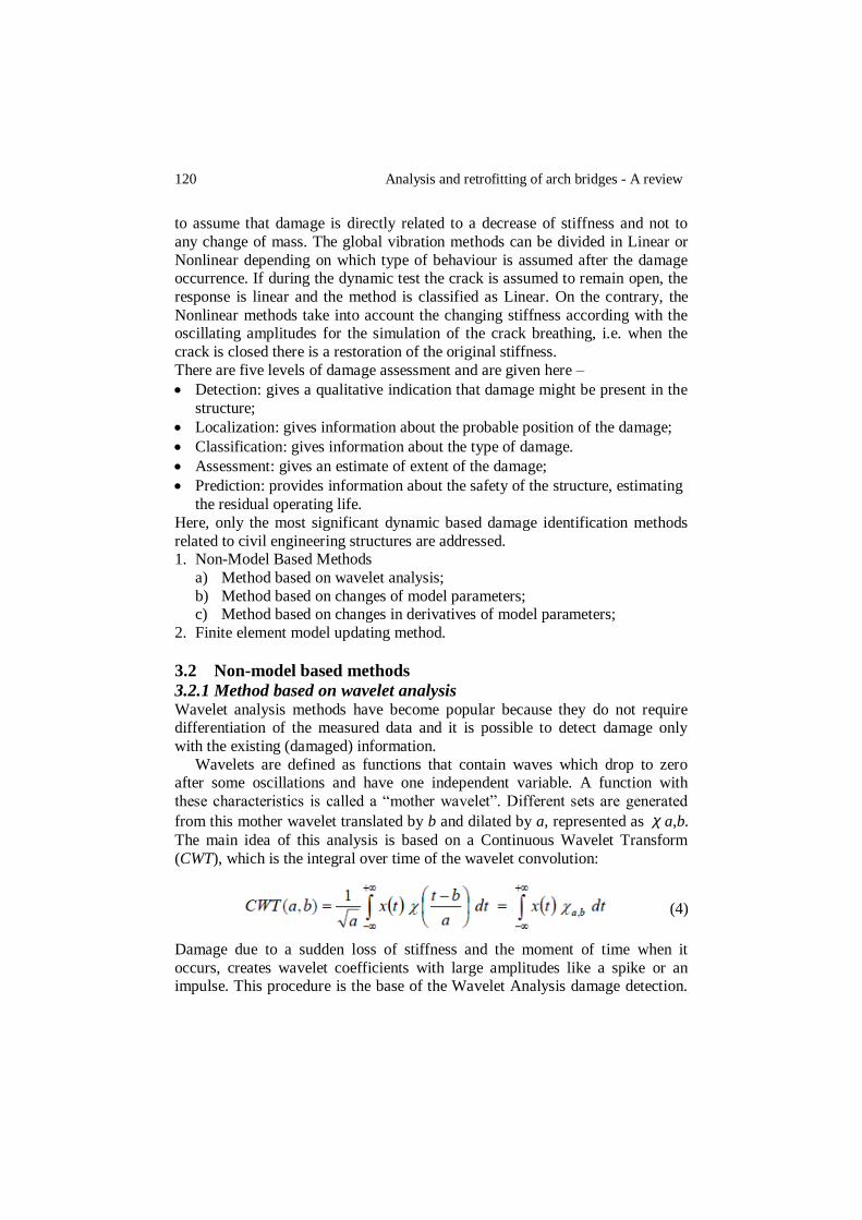
The main idea of this analysis is based on a Continuous Wavelet Transform
(CWT), which is the integral over time of the wavelet convolution:
(4)
Damage due to a sudden loss of stiffness and the moment of time when it
occurs, creates wavelet coefficients with large amplitudes like a spike or an impulse. This procedure is the base of the Wavelet Analysis damage detection.

Mittal & Vutukuru 121
The main advantage gained by using wavelets is the ability to perform local
analysis of a signal, i.e., zooming on any interval of time or space.
One possible drawback is that the frequency resolution is quite poor in the higher frequency region. Hence, the method still faces difficulties when
discriminating the signals containing close high frequency components.
The Wavelet Packet Decomposition (WPD) is a generalization of the wavelet transform, defined as the linear decomposition of the evaluated
function. In WPD the signal is decomposed in approximations and details, these
two results are themselves decomposed into another level of decomposition.
Then this process is repeated until the required level of accuracy is achieved. It consists of a set of linearly combined wavelet functions. The wavelet packets
inherit the properties such as orthonormality and time-frequency localization
from their corresponding wavelet functions. A wavelet packet χij,k(t) is a
function with three indices where integers i, j and k are the modulation, dilation
and translation parameters, respectively.
Chang et.al [10] proposed Wavelet Packet Signature (WPS) method which obtains the entropy energy E of the dynamic response at measured points and
calculated the spatial WPS by the second derivative of the entropy energy along
the structure. The component energies are calculated as
(5)
After extracting the WPS from the response measured at various locations, the
spatial distribution curvature of the WPS is used for locating damage.
3.2.2 Method based on direct change of model parameters Cawley and Adams [11] proposed a method based on the calculation of the ratio between frequencies for modes i and j, δωi/δωj. A grid of possible damage is
considered and an error term is defined to correlate the estimated frequencies
with the model based predicted frequencies. In the numerical model, the
damage is simulated by a local stiffness reduction and a number of mode pairs are considered for each potential damage location. The mode pair that gives the
lowest error indicates the location of the damage. One disadvantage of this
formulation is that it cannot be applied in cases of multi-damage scenarios. Later, Brincker et al., proposed a statistical analysis method to detect
damage by frequencies shifts. By estimating the undamaged and the damage
condition of the structure for five selected instants of time, the authors define a significance indicator for the j
th resonant frequency as:
(6)

122 Analysis and retrofitting of arch bridges - A review
Where σω is the estimated standard deviation (resulted from the five system
identification tests) of the jth
resonant frequency and the super scripts u and d
indicates the undamaged and the damage state, respectively. The significance indicator proved to be a sensitive indicator of structural damage (Level 1), but it
is not capable of providing an estimate of damage location (Level 2). A possible enhancement consists of analysing not only shifts in resonant
frequencies but also in the mode shape vectors. Mode shape vectors are
spatially distributed quantities and they provide information that can be used to
identify damage. In order to have accurate results with these quantities, Farrar
and Doebling [13] stress from the fact that a large number of measurement locations can be required to accurately characterize the mode shapes and to
provide sufficient resolution for the damage identification methods.
When results are available from two scenarios, e.g. undamaged and damaged stage, the most well-known procedure to study the numerical correlation
between two sets of mode shape vectors is to use the Modal Assurance Criteria
(MAC) value, given by:
(7)
Where ϕu and ϕ
d are the mode shape vectors for the two different stage
conditions and n indicates the number of estimated degrees of freedom. The
expression leads to a scalar value between zero and one, associated with low
and high correlation between the two vectors. The disadvantage of using this
indicator is the fact that MAC values are global quantities and they are not sensitive to low damage in the structure.
The Normalised Modal Difference (NMD) value is more sensitive to the
differences between the shape vectors [14]. After the MACs calculation, the NMD can be calculated as:
(8)
In practice, one might consider that a NMD value less that 33% (MAC value greater than 0.90) between to modes is an indicator of a good correlation
between the two modes.
3.2.3 Method based on changes in derivatives of model parameters
finite element model updating method It is based on optimization processes to minimize the residuals between the

Mittal & Vutukuru 123
experimental response and the mathematical response (model based and inverse
methods). A sensitive matrix for the resonant frequencies was constructed
numerically and was compared with the estimated frequencies, which allowed the location and magnitude of damage. Nevertheless, the sensitivity method
leads to an ill-conditioned problem if the number of modes is much lower than
the number of damage parameters. Damage identification by means of FE model updating (FEMU) has the
advantage of being a general approach. This is shown in the form of a flow
chart as
3.3 Non-destructive test for structural evaluation of masonry arch
bridge Non-destructive test are the structural evaluation technique which is based on
visual inspection and experimental tests of ultrasonic methods, magnetic field methods, flat jack test, ground etc. during which cracks, spalling, displacement,
staining, bulging, missing mortar and other sign of damages are recorded.
3.4 Flat jack test A thin flat-jack is placed inside the cut and the pressure is gradually increased to
obtain the distance measured before the cut. The displacement cause by the slot and the ones subsequently induced by the flat-jack are measured by a removable
extensometer. With the values of displacements and pressure applied to regain
the original position, the stress value can be determined. The test can also be used to determine the deformability characteristics of
masonry; this is called a double flat-jack test. A second cut is made parallel to

124 Analysis and retrofitting of arch bridges - A review
the first one and a second jack is inserted. The two jacks in a sense isolate a
masonry sample of appreciable size to which a uni-axial compression stress can
be applied. The test gives a good approximation of the stress-strain behaviour.
Photo 1. Flat Jack Test Apparatus
3.5 Acoustic emission
AE signals are high frequency energy waves, which are emitted by the material when damage such as crack initiation and propagation, occurs. This monitors
the condition of components of masonry structures subjected to tension and
distortion states. It tells about the prediction of crack growth co-relating the evolution of cracks with the commutative counting of acoustic emission events.
The creep test has shown that the AE technique is a very valuable tool to
monitor progressing damage in masonry and could even be used as a warning
system for masonry structures, subjected to the creep failure mode. The monitoring of acoustic emissions during the creep tests enables to quantify the
damage events from which they are originated.
3.6 Ground penetrating radar test Ground Penetration Radar test can be used in any type of masonry and can emit
at long distances. It can be used to establish uniformity, detect flaws and delaminations, and the thickness. It only requires access to one surface.
However, the test seems to have no direct correlation with the properties, the
wave analysis is complicated and the process is expensive. This method is used to study the interior of the masonry structure and presence of the metallic bar in
the section of the structure. This method is also used to locate the presence of
structural disorders like crack, voids crack growth and continuous data set etc.

Mittal & Vutukuru 125
Photo 2. Acoustic Emission Test Apparatus
3.7 Sonic wave test Sonic tests are NDT techniques used on masonry characterization and gives results such as qualification of the masonry through the morphology of the wall
section, detection of internal defects (voids, cracks) or changes to physical
characteristics of the wall, control repair using the injection technique. Sonic
test aims to estimate the global Young´s modulus, E by measuring the velocity of propagation of the elastic compression, P, and surface (Rayleigh), R, waves
through direct and indirect tests. The relationship between P-wave (Vp) and the
R-wave (Vr) velocities with Young´s modulus (E) and Poisson´s ratio (υ) for a homogeneous material are given by:
(9)
3.8 Infrared thermography It is a technique for converting a thermal radiation pattern which is invisible to
the human eye into a visual image. This technique can be used to detect
delamination, build-up of water behind the surface, voids or cracks. It is used to know the interior of the structure. It basically measures the temperature of the
surface. It tells about the moisture condition. It is used to identify the possible
areas of defects such as moisture condition in the fill of masonry bridge,
delamination etc.

126 Analysis and retrofitting of arch bridges - A review
3.9 Fibre optics method This technique allows the viewing of the interior of inaccessible areas by inserting a fiberscope (a bundle of flexible optical fibres) or a borescope (a
bundle of rigid optical fibres) into the void. Both carry the high intensity light
along their length. While the technique is marginally useful for solid masonry
structures with limited voids, it has been used successfully on masonry cavity wall construction. In engineering, it is mainly used to monitor deformation or
the overall integrity of structural components with high level of risks or with
high safety requirements.
3.10 Electromagnetic detection Commonly used for locating rebar, this technique involves passing an
alternating current through a coil to generate a magnetic field. When a magnetic
material is encountered, the field is disturbed. The magnitude is related to the size of the object and proximity to the probe. This Non-destructive evaluation
technique is recommended for use in conjunction with other techniques to
determine the presence of hidden metallic objects.
3.11 Finite element analysis of masonry arch bridge This method can be applied to any irregular shaped structure with its structural indeterminacy. Finite element method accounts for non-homogenous properties
of the material, boundary conditions, type of the load distribution and interface
conditions etc. This method gives the accurate analysis results which are almost
equivalent to the outputs from experimental tests. The modelling of the masonry arch bridge can be done using either of the software LUSAS or DIANA. For the
non-linear finite element analysis, standard smeared cracking model was used.
While modelling in FEM software the following conclusions are observed
While selecting different type of mesh elements, the magnitude and trend of
stress distribution seemed to be almost identical. A slight variation in the
shear stress was noticed but its magnitude was insignificant.
By changing the support conditions, normal and shear stresses on the arch
extrados obtained were almost identical because the far enough away for it to have any significance influence on the stress state on the arch extrados.
No significant change in arch vertical and horizontal deflection was noticed
by changing interface elements. It was also concluded that there is
negligible difference in deflection by giving or not giving interface
elements.
Compressive strength of the arch ring and pier in the case for multi span
bridge had some effect on the collapse load but did not affect the initial load
vs deflection characteristics.
Tensile strength of the arch ring is significantly affected the collapse load.
The load dispersion angle through the backfills had some influence on the

Mittal & Vutukuru 127
collapse load with wider dispersion angle giving reduced extrados stresses,
hence lower deformation and higher collapse load.
Elastic modulus of the arch ring and pier in the case for multi span bridge
had no significance effect on the collapse load, but did affect the lower load.
Davy found that collapse load was two and half time higher in presence of
the fill than in the absence.
Increasing the number of mesh elements will increase the accuracy of the
results. Material properties can be easily calculated using sonic wave test. Generally, the load dispersion angle is to be given as 45
0. As there is no
significant effect of changing the boundary conditions, so boundary conditions
can be given as either hinged or roller support. Damage, voids, crack growth,
delaminated layers etc. occurring in the masonry arch structure can be modelled by knowing about these from Non Destructive test. The load is applied at the
¼th span of the bridge as it is the most critical point because during the
collapse, first hinge takes place at this location. Cyclic loading is applied with slight increment till the required numbers of hinges are formed and collapse
takes place. It was concluded that cyclic load capacity of the masonry arch
bridges is significantly lower (up to 60%) than the static load capacity. Under the cyclic loading, multi ring arches failed by the ring separation at significantly
lower loads than that associated with the four hinged mechanism. Thus, from
the analysis, ultimate strength of the masonry arch bridge can be obtained.
Variation of crack and its pattern can also be seen by vibrations analysis of the structure.
4 RETROFITTING
4.1 Grouting It is often used to fill voids caused by ring separation (or cracks) in multi-ring brick arches or between the ring and backing/fill. For this application, however,
it is important to determine if the bond will be sufficient between the grout and
existing masonry. If not, cracks are likely to occur at the interface and the intervention is ineffective. In the spandrel walls, grout strengthens against
lateral forces by re-establishing the unity of the wall. Grouting in itself does not
provide any substantial increase in load capacity, but rather restores the bridge
to a former condition and protects the structure from further deterioration. The repair is only minor and is usually done in conjunction with a strengthening
technique.
It is important to repair masonry fabrics with adequate and compatible mortars because the properties of a mortar determine the durability,
compressive strength, flexural and tensile bond strengths of the masonry. In
general, lime mortars are more compatible with most masonry materials than
artificial cements as lime mortars are porous, permeable and flexible, they do not contain elements capable of forming salts, they develop a good bond with

128 Analysis and retrofitting of arch bridges - A review
masonry units and their compressive strengths are suitable to withstand typical
stresses in masonry structures.
4.2 Repointing Repointing is simply the process of refilling deteriorated joints between
masonry units. It may restore the load capacity of an arch by restoring the structurally effective arch ring thickness to its full depth, but does not increase
load capacity. For proper repointing, raking out of the joints should first be done
to a minimum depth of 15mm. Power tools should be avoided because they may cause more damage to the masonry work. Bucket handle or struck and
weathered joints should be used for finishing as they contribute to brickwork
durability because the tooling of the joints reduces the permeability of the mortar surface and improves the seal between the bricks and mortar. Recessed
joints can increase the level of saturation along the upper arises of the bricks
and may lead to frost and damage. Costs of repair are low and traffic or service
disruptions do not occur except possible short delays in waterway traffic. Repointing repair works can prevent the bridge from needing larger, more
expensive strengthening techniques in the future.
Figure 1. Before and after repointing
4.3 Injections Similar to grouting, injections use grout to fill voids in the fill and backing,
deeper than near-surface. The injection fill can increase load capacity by improving load distribution to the arch and abutments or piers, and by
increasing the weight of the piers or abutments to resist horizontal thrust. It can
also be a preventative measure to slow further deterioration of the structure. For installation, a matrix of holes is drilled into the structure, flushed with water to
clear debris, and then injected with grout starting at the lowest point and
working upwards. Grout is injected with a pressure grouting machine until the pressure limit is reached, until it appears at adjacent holes, or until a
predetermined amount has been injected. Pressure should be kept to a minimum

Mittal & Vutukuru 129
as not to cause internal damage to the bridge. After injection, the hole is
plugged with a core from the drilling or other piece of brick or stone with
similar appearance to the existing material. If injection holes are properly plugged, the intervention will have no negative effects on the appearance. The
costs of injections are similar to that of grouting but will incur additional costs
in the amount of grout needed and additional equipment.
Figure 2. Method of injection of grout
4.4 Replacing units It is possible that a small unit in the masonry structure can deteriorate because
of the exposure or local stresses have caused a unit to detach and protrude from
the structure. To regain the effective section in the arch ring and help prevent further deterioration, these units should be replaced. When these units are in the
exterior walls, the thinner, weaker section can allow lateral forces to push the
wall out, creating a bulge and possibly lead to more severe damages.
When replacing parts of the arch ring, it is necessary to provide temporary formwork in order to prevent any undesirable movements or collapse. During
the process, structures with mortar joints will require repointing and grouting in
conjunction with it. Replacing individual units is a fairly simple and low-cost method of repairing which will also prevent the problem from developing into a
more serious damage.

130 Analysis and retrofitting of arch bridges - A review
4.5 Saddling
Saddling involves excavation of the fill and casting of an in-situ concrete arch, which may be reinforced, on top of the existing arch (on the extrados). The
concrete is typically of a weaker strength to provide a better compatibility with
the masonry. The technique is often combined with spandrel wall repairs, or fill
and backing repair and it also allows for waterproofing of the structure. Polypropylene fibres give resistance to surface shrinkage cracking, where
stainless steel fibres give considerable strength and structural ability to unite
arches and to bind cracks. Once the concrete has set, backfill and surfacing may be replaced. Saddles may be poured monolithically with varying cross section
thickness or may be poured with uniform thickness and are shown below:
Figure 3. Method of saddling
4.6 Sprayed concrete Sprayed concrete (Gunite) is traditionally used to increase the thickness of the
arch ring in an effort to increase load capacity and to stabilize and protect
weathered masonry. The sprayed concrete is usually applied to the existing intrados of the arch ring. The sprayed concrete is often used in conjunction with
a reinforcing mesh. Pre-mixed concrete is sprayed at a high velocity and
adheres on impact, filling crevices and compacting material already sprayed.
Plasticizers are usually used in the mix in order to gain the right consistency for

Mittal & Vutukuru 131
such application. The concrete is applied in a layer between 150mm and 300mm
thick and usually reinforced with a mesh (usually of nominal size steel). The
method is relatively quick to apply and does not require long term closure of the bridge (only an adequate time for concrete to gain strength). Nor does it require
extensive formwork for application. Costs are less expensive than saddles
because excavation is not needed and the number of man hours is significantly decreased. Visually, however, it can be very degrading and is not recommended
for any bridges of historical or cultural value. The layer of concrete will also
decrease the amount of headroom in the arch.
Figure 4. Spraying of concrete
4.7 Pre-fabricated liners Prefabricated liners are typically made of corrugated metal or glass reinforced
cement and attached to the intrados of the arch. The space between the liner and arch ring is filled with concrete or grout. The liners provide an increase in load
capacity by supporting the arch and giving it more resistance. With the concrete
between the liner and arch ring the thickness of the arch is increased which in turn also increases the load capacity. In addition, when filling the space between
the existing arch and liner, cracks, missing mortar and voids will also be filled
in. Care must be taken to ensure the space is fully filled in to maintain the
increased section across the whole arch.

132 Analysis and retrofitting of arch bridges - A review
Figure 5. Use of pre-fabricated liners
4.8 Near-surface reinforcement In this technique, stainless steel reinforcing bars are grouted into pre-drilled
holes or pre-sawn grooves in the exposed near-surface zones of the masonry
where tensile stresses arising from external loads or settlement effects are likely to result in cracking.
For near-surface reinforcement to be effective, it must act compositely with
the existing masonry. Thus, the selection of grouting material that is compatible with the existing structure is necessary to ensure no increase in local stresses or
premature bond failure at the interface of the grout, masonry and reinforcement.
Prior to the installation of the system, grout should be injected where there
are large voids or evidence of ring separation. Procedures should be followed as followed as found in the sections on grouting and injections. Once grout has
time to set, transverse holes are then drilled into the arch barrel. Stainless steel
reinforcing bars are installed into the holes and then grout is pumped into the holes, encapsulating the reinforcement. The reinforcement helps improve lateral
load distribution and increases the transverse flexural strength of the arch. To
preserve the aesthetic look of the bridge, the holes should be plugged with grout or stone matching the colour of the stone. Next, longitudinal grooves are sawed
into the intrados of the arch barrel and a grout is injected into each groove. The
stainless steel reinforcing is then installed with spacers to provide proper
placement and to ensure that each bar is fully encapsulated with grout. Additional grouting is injected over the reinforcing.

Mittal & Vutukuru 133
Photo 3. Near surface reinforcement
Another technique which utilizes near surface reinforcement in the arches is a method called Archtec. Steel is placed at an approximate tangent position to
these critical positions in the arch ring. The reinforcement is usually installed
from above using accurately positioned drilled holes through the fill and into the arch ring. The steel bars are grouted in place using a fabric sock grout
delivery system to ensure consistent bond with the surrounding masonry.
Placing the reinforcement across transverse cracks can also help stabilize crack growth.
Figure 6. Arc tech method
4.9 Fibre reinforced polymer The typical way to use FRP in strengthening masonry arches has been to apply sheets at the intrados and/or extrados. The application of FRP sheets to an arch
modifies the classical mechanisms of collapse in masonry arches (without
reinforcement). The mechanisms are also altered according to which surface the FRP is applied (extrados, intrados, or both). This occurs because the fibres can

134 Analysis and retrofitting of arch bridges - A review
bear the stresses at the tensed edges of the typical failure sections, which are in
combined compressive and bending stresses. The resistance in the arch is now
similar to reinforced concrete, dependent on the masonry compression strength and on the fibre tensile strength, which is very high. FRP strengthening is
certainly not as labour intensive and has a longer life than other strengthening
techniques. Particularly when FRP is only applied to the intrados, installation can be completed very quickly and usually without traffic or service disruptions.
When application is required on the extrados, traffic and service disruptions
should be planned on.
4.10 Anchoring Anchoring and radial pinning will increase the stiffness and the elastic properties of the arch barrel and limit movement. When significant longitudinal
cracking is detected in the intrados of an arch or spandrel walls are detached,
anchoring is a viable option for restoring shear transfer and continuity. Ring
separation occurs more often and a type of anchored called radial pinning can be used to restore the loss in integrity caused by ring separation and prevent
further separation. Both processes may require replacing or resetting some units
in the intrados or spandrel wall, as well as repointing and/or grouting. After replacing and resetting, oversized holes are drilled using a rotating drilling
device through the full width of the bridge or through the ring to a pre-defined
depth into backing and fill. The anchors can be designed using retaining wall theory. There is no specification known at this time relating to suitable spacing
for tie bars. Engineering judgment should be used in determining spacing. After
holes are drilled, stainless steel rods encased by a sleeve are placed in the holes
and then grouted under low pressure. As with any intervention involving the addition of grout in masonry, care should be taken in the selection and
compatibility. The sleeve prevents grout from being lost in voids. The rods are
secured to steel anchorage plates at each side of the arch (only on the visible end for radial pinning). To help prevent corroding, grease or other sealant
should be used over the exposed bar and plate. Corrosion can cause small, local
movements in the structure and corrosion stains. To decrease negative visual
effects from the intervention, the plates are usually set in from the face of the stone and plugged with grout and a cylinder of stone from the borehole. In some
cases the radial pinning may be done on the outer face of the arch and walls,
however, this greatly affects the visual appearance of the bridge.

Mittal & Vutukuru 135
Figure 7. Anchoring and radial pinning method
4.11 Relieving slabs Relieving slabs (also called overslabbing) are flat reinforced concrete slabs
placed on top of the fill. They improve the bridge through better distribution of loads on the arch and alters the line of thrust to allow appropriate load transfer
to the abutments. In some cases a compressible layer is installed under the
central section of the slab to relieve the arch of more live load. Lateral pressure on the spandrel walls is reduced and the slab allows for a good waterproofing to
keep water out of the structure. If an increase in the road height presents no
problems and rearranging of the fill is not necessary, it is possible for the slab to be applied directly on top of the current surface with little or no excavation.
Figure 8. Use of relieving slabs
It is recommended at minimum to remove the current road surface and place the
slab over the fill. Excavation should be done symmetrically on both sides of the crown. Design of the slab will be the same as a concrete roadway supported at

136 Analysis and retrofitting of arch bridges - A review
two ends. Reinforcement, clear cover and other design considerations should
comply with the code provisions for road surfaces. Relieving slabs are cheaper
and easy to construct than saddles.
4.12 Invert slab An invert slab is a slab of concrete placed between the abutment walls or piers with its top surface at or below river bed level. The method is used in bridges
which cross over flowing water and it helps prevent scour of river bed under the
foundations. Often times a downstand beam (deep beam) at each end of the slab will be installed to increase the protection against scour or undercutting of the
slab itself. The slabs should typically be reinforced using nominal steel with
appropriate clear cover for underwater concrete. The design is typically done as a slab supported at each end. Additionally, proper strength requirements to prop
the abutments should be considered in the design. Invert slabs are a low cost
and speedy intervention. The construction process does not disrupt road surface
traffic and typically does not disrupt services except in the case of those on the stream bed near the bridge. Invert slabs also provide a firm river bed which may
be useful in the future when further interventions may be done on the intrados
of the arch (i.e. provides a firm foundation for scaffolding or other supports).
Figure 9. Technique of invert slabbing
4.13 Underpinning It is similar to invert slabs and involves excavating of soil and other material from beneath the existing foundations and replacing with mass concrete.
Underpinning is useful in stabilizing the foundation, preventing future damage
from scour or settlement. It is also useful for bridges where stream beds have
been lowered, whether by natural causes or by dredging to provide deeper water for ships.
Mittal & Vutukuru 137
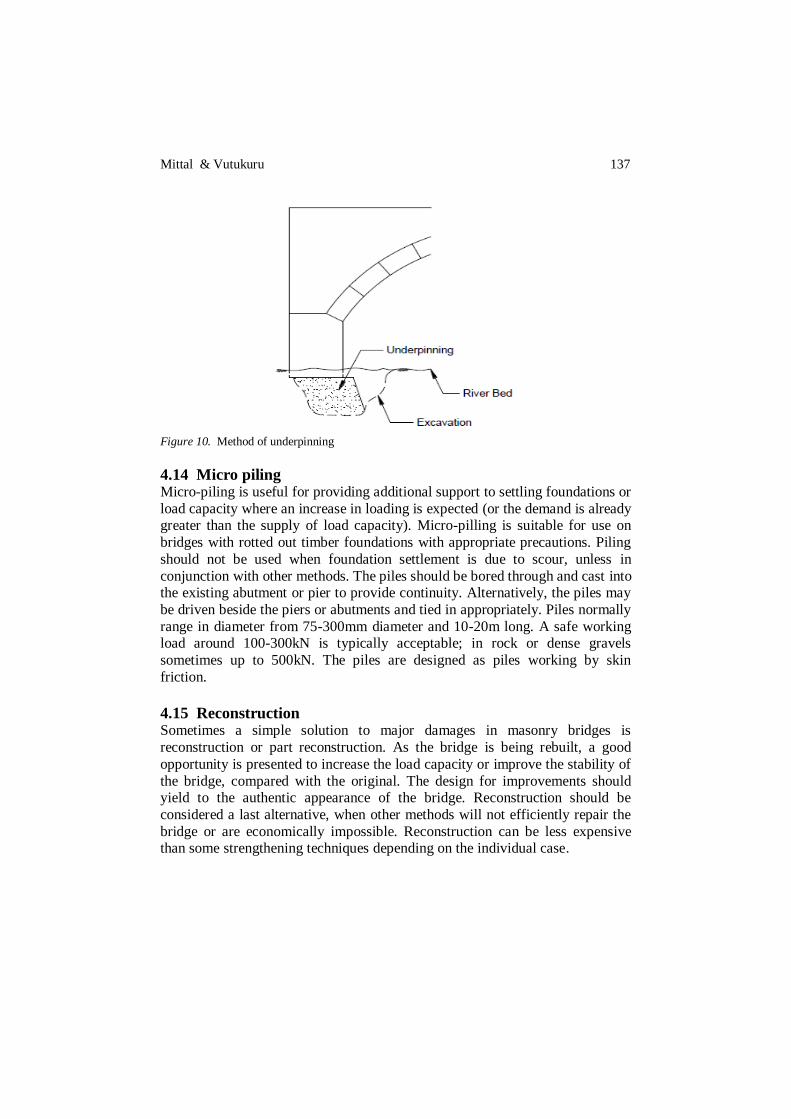
Figure 10. Method of underpinning
4.14 Micro piling Micro-piling is useful for providing additional support to settling foundations or
load capacity where an increase in loading is expected (or the demand is already greater than the supply of load capacity). Micro-pilling is suitable for use on
bridges with rotted out timber foundations with appropriate precautions. Piling
should not be used when foundation settlement is due to scour, unless in
conjunction with other methods. The piles should be bored through and cast into the existing abutment or pier to provide continuity. Alternatively, the piles may
be driven beside the piers or abutments and tied in appropriately. Piles normally
range in diameter from 75-300mm diameter and 10-20m long. A safe working load around 100-300kN is typically acceptable; in rock or dense gravels
sometimes up to 500kN. The piles are designed as piles working by skin
friction.
4.15 Reconstruction Sometimes a simple solution to major damages in masonry bridges is
reconstruction or part reconstruction. As the bridge is being rebuilt, a good
opportunity is presented to increase the load capacity or improve the stability of
the bridge, compared with the original. The design for improvements should yield to the authentic appearance of the bridge. Reconstruction should be
considered a last alternative, when other methods will not efficiently repair the
bridge or are economically impossible. Reconstruction can be less expensive than some strengthening techniques depending on the individual case.

138 Analysis and retrofitting of arch bridges - A review
5 CONCLUSIONS Various methods of analysis (both dynamic and static analysis) are provided and are explained in detail along with aids needed to perform analysis along
with damage detection methods. Various techniques for retrofitting of masonry
arch bridges are discussed based on analysis results and the extent of damage.
Also the selective use of these retrofitting techniques is provided.
REFERENCES [1] Pippard, A. J. S., Tranter, E. & Chitty, L. (1936), “The mechanics of the voussoir arch”, J.
Instn Civ. Engnrs, 4, pp. 281-306. [2] Heyman, J. (1980), “The estimation of the strength of masonry arches”, Proc. Instn Civ.
Engnrs, 69, pp. 921-937. [3] Sawko, F. & Towler, K (1982), “Structural behaviour of brickwork arches”, Proc. Brit.
Ceram. Soc., 30, pp. 160-168. [4] Sawko, F. & Rouf, M. (1985), “A proposed numerical model for structural Masonry”, J.
Brit. Mas. Soc., 5, pp. 22-27. [5] Hughes, T. G. (1995), “The assessment of a multi-span masonry arch bridge”, Proc. Ist Int.
Cone Arch Bridges, Bolton, pp. 489-497. [6] Melbourne, C. & Wagstaff, M. (1992), “A study of the load carrying capacity of multi-span
masonry arch bridges”, Internal Report, Bolton Inst. Higher Educ., Bolton [7] Loo, Y. C. & Yang, Y. (1991), “Cracking and failure analysis of masonry arch bridges”,
Proc. Am. Soc. Civ. Engnrs, J. Struct. Engg, 117,6, pp. 1641-1659. [8] Vestroni, F.; Beolchini, G.C.; Antonacci, E.; and Modena, C. (1996), “Identification of
Dynamic Characteristics of Masonry Buildings from Forced Vibration Tests”, Proceedings of the 11th World Conference on Earthquake Engineering.
[9] De Sortis, A.; Antonacci, E.; and Vestroni, E. (2005), “Dynamic identification of a masonry building using forced vibration tests”, Engineering Structures, Vol. 27, pp. 155-165.
[10] Chang, P.C.; Flatau, A.; and Liu, S.C. (2003), “Review Paper: Health Monitoring of Civil Infrastructure”, Structural Health Monitoring, Vol. 2 (3), pp. 257-267.
[11] Cawley, P.; and Adams, R.D. (1979), “The Locations of Defects in Structures from Measurements of Natural Frequencies”, Journal of Strain Analysis, Vol. 14 No. 2, pp. 49-57.
[12] Brincker, R.; Ventura, C.; and Andersen, P. (2001), “Damping Estimation by Frequency Domain Decomposition”, Proceedings of IMAC XIX, the 19th International Modal Analysis Conference, Kissimee, USA.
[13] Farrar, C.R. and Doebling, S.W. (1998), “Damage Detection and Evaluation II – Field Applications to Large Structures, Modal Analysis and Testing”, Júlio Silva and Nuno Maia (Editors), NATO Science Series E, Vol. 363, Kluwer Academic Publishers, London, pp 345-378.
[14] Gentile, C.; Martinez, F.; and Cabrera (2001), “Dynamic assessment of a curved cable stayed bridge at the Malpensa 2000 Airport, Milan, Italy”, Structural Engineering International, (1),
pp. 52–58. [15] Chopra, A.K. (2001), “Dynamics of Structures, Theory and Applications to Earthquake
Engineering”, Second Edition, Prentice Hall.