Embed Size (px)
Citation preview
International Research Journal of Engineering and Technology (IRJET) e-ISSN: 2395-0056
Volume: 05 Issue: 02 | Feb-2018 www.irjet.net p-ISSN: 2395-0072
© 2018, IRJET | Impact Factor value: 6.171 | ISO 9001:2008 Certified Journal | Page 989
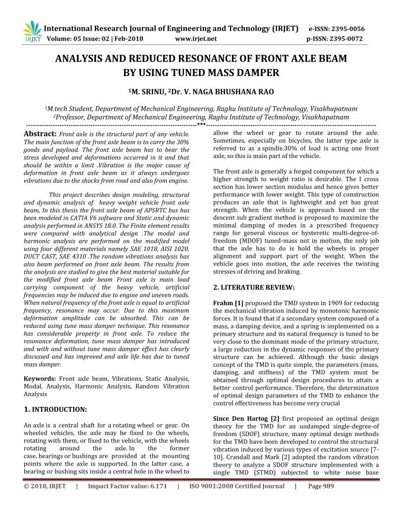
ANALYSIS AND REDUCED RESONANCE OF FRONT AXLE BEAM
BY USING TUNED MASS DAMPER
1M. SRINU, 2Dr. V. NAGA BHUSHANA RAO
1M.tech Student, Department of Mechanical Engineering, Raghu Institute of Technology, Visakhapatnam 2Professor, Department of Mechanical Engineering, Raghu Institute of Technology, Visakhapatnam
-----------------------------------------------------------------------------***-----------------------------------------------------------------------------
Abstract: Front axle is the structural part of any vehicle. The main function of the front axle beam is to carry the 30% goods and payload. The front axle beam has to bear the stress developed and deformations occurred in it and that should be within a limit .Vibration is the major cause of deformation in front axle beam as it always undergoes vibrations due to the shocks from road and also from engine.
This project describes design modeling, structural and dynamic analysis of heavy weight vehicle front axle beam, In this thesis the front axle beam of APSRTC bus has been modeled in CATIA V6 software and Static and dynamic analysis performed in ANSYS 18.0. The Finite element results were compared with analytical design .The modal and harmonic analysis are performed on the modified model using four different materials namely SAE 1018, AISI 1020, DUCT CAST, SAE 4310 .The random vibrations analysis has also beam performed on front axle beam. The results from the analysis are studied to give the best material suitable for the modified front axle beam Front axle is main load carrying component of the heavy vehicle, artificial frequencies may be induced due to engine and uneven roads. When natural frequency of the front axle is equal to artificial frequency, resonance may occur. Due to this maximum deformation amplitude can be absorbed. This can be reduced using tune mass damper technique. This resonance has considerable property in front axle. To reduce the resonance deformation, tune mass damper has introduced and with and without tune mass damper effect has clearly discussed and has improved and axle life has due to tuned mass damper.
Keywords: Front axle beam, Vibrations, Static Analysis, Modal, Analysis, Harmonic Analysis, Random Vibration Analysis
1. INTRODUCTION: An axle is a central shaft for a rotating wheel or gear. On wheeled vehicles, the axle may be fixed to the wheels, rotating with them, or fixed to the vehicle, with the wheels rotating around the axle. In the former case, bearings or bushings are provided at the mounting points where the axle is supported. In the latter case, a bearing or bushing sits inside a central hole in the wheel to
allow the wheel or gear to rotate around the axle. Sometimes, especially on bicycles, the latter type axle is referred to as a spindle.30% of load is acting one front axle, so this is main part of the vehicle. The front axle is generally a forged component for which a higher strength to weight ratio is desirable. The I cross section has lower section modulus and hence gives better performance with lower weight. This type of construction produces an axle that is lightweight and yet has great strength. When the vehicle is approach based on the descent sub gradient method is proposed to maximize the minimal damping of modes in a prescribed frequency range for general viscous or hysteretic multi-degree-of-freedom (MDOF) tuned-mass not in motion, the only job that the axle has to do is hold the wheels in proper alignment and support part of the weight. When the vehicle goes into motion, the axle receives the twisting stresses of driving and braking.
2. LITERATURE REVIEW:
Frahm [1] proposed the TMD system in 1909 for reducing the mechanical vibration induced by monotonic harmonic forces. It is found that if a secondary system composed of a mass, a damping device, and a spring is implemented on a primary structure and its natural frequency is tuned to be very close to the dominant mode of the primary structure, a large reduction in the dynamic responses of the primary structure can be achieved. Although the basic design concept of the TMD is quite simple, the parameters (mass, damping, and stiffness) of the TMD system must be obtained through optimal design procedures to attain a better control performance. Therefore, the determination of optimal design parameters of the TMD to enhance the control effectiveness has become very crucial Since Den Hartog [2] first proposed an optimal design theory for the TMD for an undamped single-degree-of freedom (SDOF) structure, many optimal design methods for the TMD have been developed to control the structural vibration induced by various types of excitation source [7-10]. Crandall and Mark [2] adopted the random vibration theory to analyze a SDOF structure implemented with a single TMD (STMD) subjected to white noise base
International Research Journal of Engineering and Technology (IRJET) e-ISSN: 2395-0056
Volume: 05 Issue: 02 | Feb-2018 www.irjet.net p-ISSN: 2395-0072
© 2018, IRJET | Impact Factor value: 6.171 | ISO 9001:2008 Certified Journal | Page 990
excitation. The results demonstrated that the TMD could effectively reduce the vibration of the base excited structure. Warburton [8 and 9] further proposed optimal design formulas for the TMD system under different types of load, such as harmonic forces, wind loads, and seismic loads.
Zuo et. al. [3] has been working for the design of a single-degree-of-freedom (SDOF) absorber to damp SDOF vibration and efficient numerical systems. When the vehicle is not in motion, the only job that the axle has to do is hold the wheels in proper alignment and support part of the weight. When the vehicle goes into motion, the axle receives the twisting stresses of driving and braking.
Sanjay Aloni et al. [4] “Comparative evaluation of tractor trolley axle by using finite element analysis approach “Studied on Evaluation of Tractor Trolley Axle by Using Finite Element Analysis to modify existing rear axle of 6.0 ton tractor trolley. Fatigue failure of the rear axle finite element model was predicted after the dynamic load was imposed on it. Spectrum analysis revealed that the failed axle shaft material is SAE 1020 steel. Fractographic features indicated that fatigue was the main cause of failure of the axle shaft. It was observed that the fatigue cracks originated from transition areas due to sharp corners. Modified axle produced with casting process with the use of ductile iron (65- 45-12 or 450-12) strengthened.
Javad Tarighi et al.[5] “Static and dynamic analysis of front axle housing of tractor using finite element methods” Studied on MT250D Mitsubishi Tractor with 25hp power is used to do light agricultural operations. Finite element analysis results showed that the maximum stress of 238.84MPa is applied on the upper housing. According to Von Misses theory, the value of maximum applied stress and allowable stress, the safety factor of 1.05 was obtained which is less than the required value. The first four natural frequencies of housing were found as 678.54, 720.29, 908.78 and 1877 Hz, respectively. The obtained factor of safety is very low. The present study clearly indicates that the front axle housing of MT250D Mitsubishi tractor is not strong enough to be mounted on a tractor
3. PROBLEMIDENTIFICATION AND OBJECTIVE:
Front axle beam must be stiff enough to withstand all the forces and loads acting on it statically and dynamically and forces like shock, twist and vibration. The vibration of the beam will cause high stress concentration at certain location loosening of mechanical joints cause noise and vehicle discomfort. Resonance is often the cause of or at least a contributing factor for too many of the vibration and noise related problems that occur in structures and operating machinery
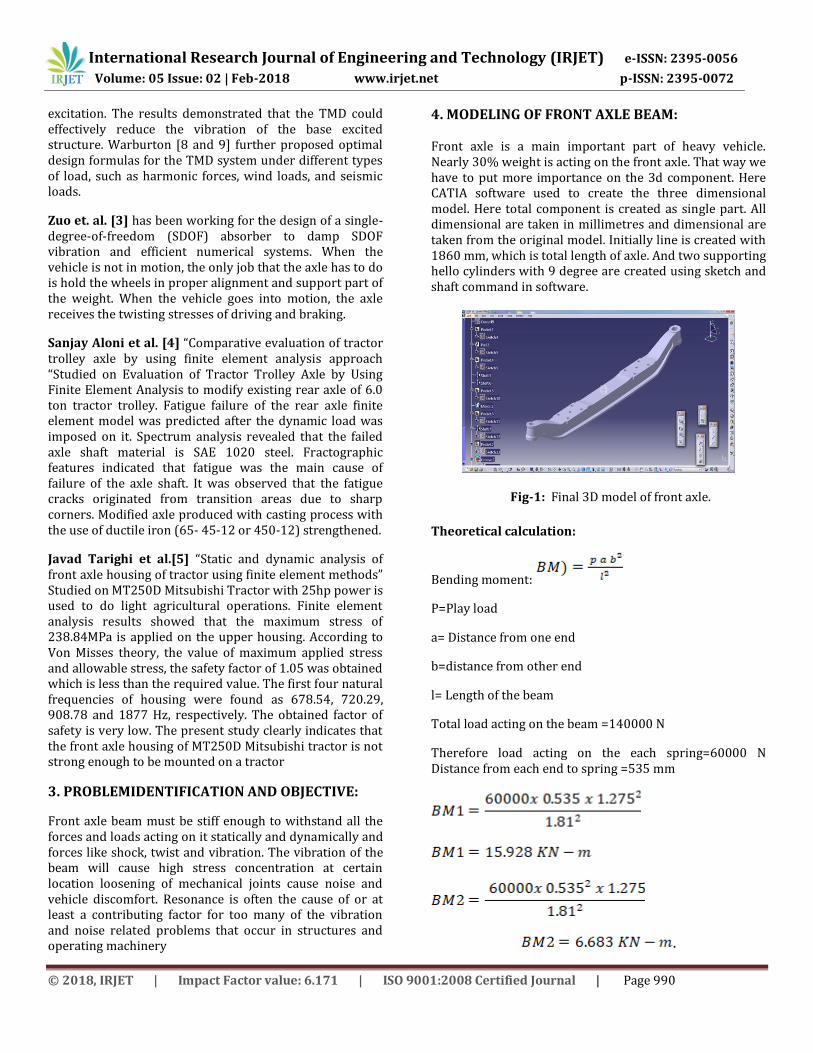
4. MODELING OF FRONT AXLE BEAM: Front axle is a main important part of heavy vehicle. Nearly 30% weight is acting on the front axle. That way we have to put more importance on the 3d component. Here CATIA software used to create the three dimensional model. Here total component is created as single part. All dimensional are taken in millimetres and dimensional are taken from the original model. Initially line is created with 1860 mm, which is total length of axle. And two supporting hello cylinders with 9 degree are created using sketch and shaft command in software.
Fig-1: Final 3D model of front axle.
Theoretical calculation:
Bending moment:
P=Play load
a= Distance from one end
b=distance from other end
l= Length of the beam
Total load acting on the beam =140000 N
Therefore load acting on the each spring=60000 N Distance from each end to spring =535 mm
.

International Research Journal of Engineering and Technology (IRJET) e-ISSN: 2395-0056
Volume: 05 Issue: 02 | Feb-2018 www.irjet.net p-ISSN: 2395-0072
© 2018, IRJET | Impact Factor value: 6.171 | ISO 9001:2008 Certified Journal | Page 991
Total bending moment =BM1+BM2= 22.6 KN-m
Required cross of the axle can be calculated using the simple bending stress equations i.e,
Yield stress of steel materials is 250 MPa, and allowable stress is considered as 180MPa.
According to this we can calculate the required cross section.
Moment of inertia ( I ) =7128000 mm^4.
Calculated cross section is compared to real front axle, we have same good agreement between calculated and real model.
Finaldeflection=
Deflection of beam axle
Bending stress can be calculated according to below formula:
Bending stress ( .
Fig-2: Detail view of front axle
Above image shows the line diagram of front axle. Here length of axle is 1.81 m and leaf seating is placed 0. 535 m from the left and right ends. Here total load is considered as 14 tones. The total weight is sum of vehicle weight and pay load also.
According to Indian transport department load should be act 70% on the rear axle and 30% load act on front axle. According to this, weight is divided 9800 Kg on the rear axle and 4000 Kg on the front axle.
Fig-3: Bending moment diagram
Bump road load conditions are taken as 3 time of individual axle load. Finally 12000 Kg load applied on the front axle. Weight on the each spring seat is 60000N load applied. Fixed beam point load acting on beam at location "a" distance from the one end and "b" distance from the other end.
Bending moment (
Total load acting on the beam =140000 N Therefore load acting on the each spring=60000 N
5: ANALYSIS OF FRONT AXLE BEAM The I.G.E.S. model what we created in CATIA software is imported into ANSYS and all dimensions are considered in
International Research Journal of Engineering and Technology (IRJET) e-ISSN: 2395-0056
Volume: 05 Issue: 02 | Feb-2018 www.irjet.net p-ISSN: 2395-0072
© 2018, IRJET | Impact Factor value: 6.171 | ISO 9001:2008 Certified Journal | Page 992
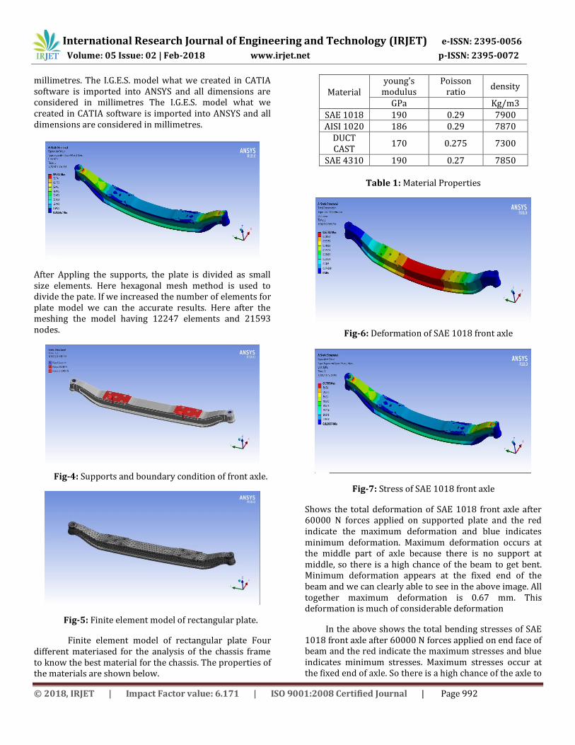
millimetres. The I.G.E.S. model what we created in CATIA software is imported into ANSYS and all dimensions are considered in millimetres The I.G.E.S. model what we created in CATIA software is imported into ANSYS and all dimensions are considered in millimetres.
After Appling the supports, the plate is divided as small size elements. Here hexagonal mesh method is used to divide the pate. If we increased the number of elements for plate model we can the accurate results. Here after the meshing the model having 12247 elements and 21593 nodes.
Fig-4: Supports and boundary condition of front axle.
Fig-5: Finite element model of rectangular plate.
Finite element model of rectangular plate Four different materiased for the analysis of the chassis frame to know the best material for the chassis. The properties of the materials are shown below.
Material young’s
modulus Poisson
ratio density
GPa
Kg/m3 SAE 1018 190 0.29 7900 AISI 1020 186 0.29 7870
DUCT CAST
170 0.275 7300
SAE 4310 190 0.27 7850
Table 1: Material Properties
Fig-6: Deformation of SAE 1018 front axle
Fig-7: Stress of SAE 1018 front axle
Shows the total deformation of SAE 1018 front axle after 60000 N forces applied on supported plate and the red indicate the maximum deformation and blue indicates minimum deformation. Maximum deformation occurs at the middle part of axle because there is no support at middle, so there is a high chance of the beam to get bent. Minimum deformation appears at the fixed end of the beam and we can clearly able to see in the above image. All together maximum deformation is 0.67 mm. This deformation is much of considerable deformation
In the above shows the total bending stresses of SAE 1018 front axle after 60000 N forces applied on end face of beam and the red indicate the maximum stresses and blue indicates minimum stresses. Maximum stresses occur at the fixed end of axle. So there is a high chance of the axle to
International Research Journal of Engineering and Technology (IRJET) e-ISSN: 2395-0056
Volume: 05 Issue: 02 | Feb-2018 www.irjet.net p-ISSN: 2395-0072
© 2018, IRJET | Impact Factor value: 6.171 | ISO 9001:2008 Certified Journal | Page 993
get failure. Minimum stress appears at the middle of the beam and we can clearly able to see in the above image. All together maximum stresses is 89 MPa. This deformation is much of considerable stresses
Remaining three materials of front axle to find the maximam and minimam stress and deformation by using ANSYS 18.0.
6. MODEL ANALYSIS:
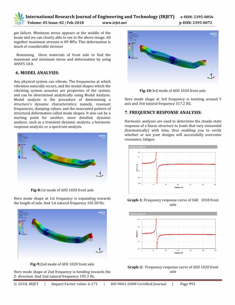
Any physical system can vibrate. The frequencies at which vibration naturally occurs, and the modal shapes which the vibrating system assumes are properties of the system, and can be determined analytically using Modal Analysis. Modal analysis is the procedure of determining a structure's dynamic characteristics; namely, resonant frequencies, damping values, and the associated pattern of structural deformation called mode shapes. It also can be a starting point for another, more detailed, dynamic analysis, such as a transient dynamic analysis, a harmonic response analysis, or a spectrum analysis.
Fig-8:1st mode of AISI 1020 front axle
Here mode shape at 1st frequency is expanding towards the length of axle. And 1st natural frequency 165.38 Hz.
Fig-9:2nd mode of AISI 1020 front axle
Here mode shape at 2nd frequency is bending towards the Z- direction. And 2nd natural frequency 195.3 Hz.
Fig-10:3rd mode of AISI 1020 front axle.
Here mode shape at 3rd frequency is twisting around Y axis and 3rd natural frequency 317.2 HZ.
7. FREQUENCY RESPONSE ANALYSIS:
Harmonic analyses are used to determine the steady-state response of a linear structure to loads that vary sinusoidal (harmonically) with time, thus enabling you to verify whether or not your designs will successfully overcome resonance, fatigue.
Graph-1: Frequency response curve of SAE 1018 front axle
Graph-2: Frequency response curve of AISI 1020 front axle

International Research Journal of Engineering and Technology (IRJET) e-ISSN: 2395-0056
Volume: 05 Issue: 02 | Feb-2018 www.irjet.net p-ISSN: 2395-0072
© 2018, IRJET | Impact Factor value: 6.171 | ISO 9001:2008 Certified Journal | Page 994
Graph-3: Frequency response curve of DUCT CAST front axle.
Graph-4: Frequency response curve of SAE 4310 front axle.
8. TUNED MASS DAMPER ON FRONT AXLE:
Tuned mass damper is one type of harmonic. Tuned mass dampers stabilize against violent motion caused by harmonic vibration. A tuned damper reduces the vibration of a system with a comparatively lightweight component so that the worst-case vibrations are less intense. Roughly speaking, practical systems are tuned to either move the main mode away from a troubling excitation frequency, or to add damping to a resonance that is difficult or expensive to damp directly. An example of the latter is a crankshaft torsion damper. Mass dampers are frequently implemented with a frictional or hydraulic component that turns mechanical kinetic energy into heat, like an automotive shock absorber.
Mass of AXLE BEAM =127 Kg (SAE 1018)
Mass of tune mass damper Mt= (3to 5 %) of mass of beam
Mt=0.05 x 127
Finally mass of tune mass damper is 3.81 kg.
Tuned frequency is 120 Hz
The use of tuned mass dampers (TMD) is another widely used passive vibration damping treatment. These devices are viscously damped 2nd order systems appended to a vibrating structure. Proper selection of the parameters of these appendages, tunes the TMD to one of the natural frequencies of the under damped flexible structure, resulting in the addition of damping to that resonance.
Fig-11: Tune mass damper model in ANSYS
Graph-5: Tune mass damper results for SAE 1018 axle.
Graph-6: Tune mass damper results for AISI 1020 axle.
International Research Journal of Engineering and Technology (IRJET) e-ISSN: 2395-0056
Volume: 05 Issue: 02 | Feb-2018 www.irjet.net p-ISSN: 2395-0072
© 2018, IRJET | Impact Factor value: 6.171 | ISO 9001:2008 Certified Journal | Page 995
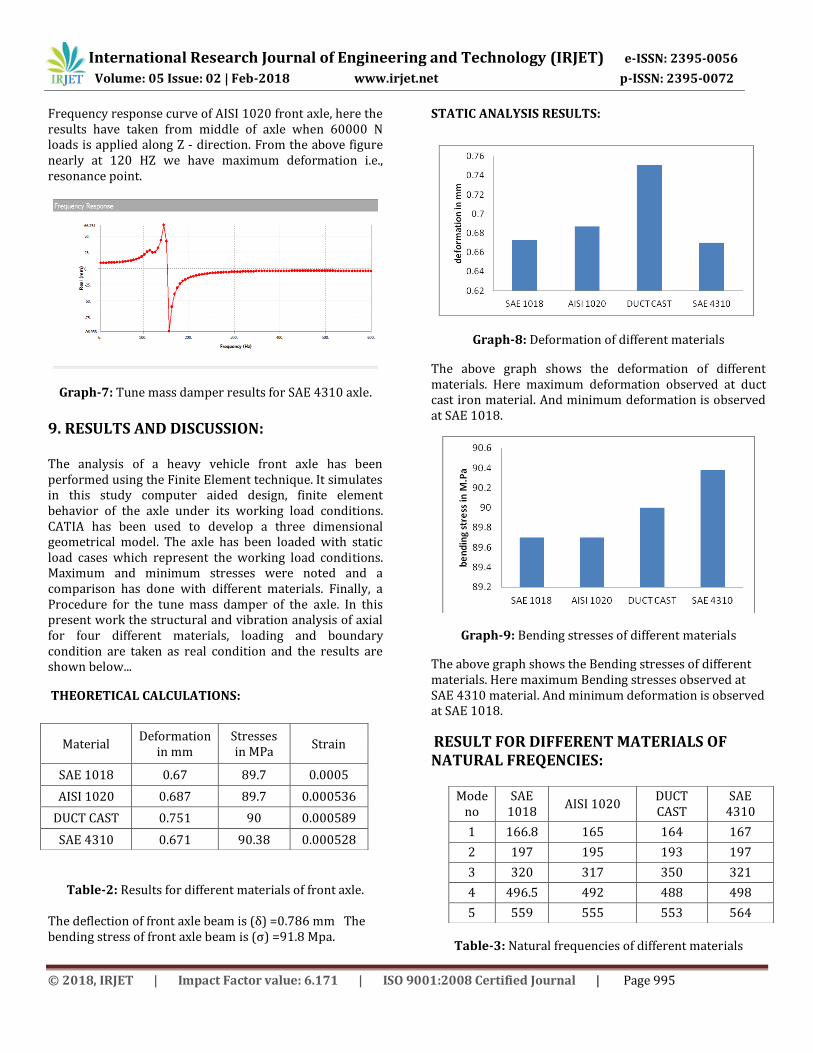
Frequency response curve of AISI 1020 front axle, here the results have taken from middle of axle when 60000 N loads is applied along Z - direction. From the above figure nearly at 120 HZ we have maximum deformation i.e., resonance point.
Graph-7: Tune mass damper results for SAE 4310 axle.
9. RESULTS AND DISCUSSION:
The analysis of a heavy vehicle front axle has been performed using the Finite Element technique. It simulates in this study computer aided design, finite element behavior of the axle under its working load conditions. CATIA has been used to develop a three dimensional geometrical model. The axle has been loaded with static load cases which represent the working load conditions. Maximum and minimum stresses were noted and a comparison has done with different materials. Finally, a Procedure for the tune mass damper of the axle. In this present work the structural and vibration analysis of axial for four different materials, loading and boundary condition are taken as real condition and the results are shown below...
THEORETICAL CALCULATIONS:
Table-2: Results for different materials of front axle.
The deflection of front axle beam is (δ) =0.786 mm The bending stress of front axle beam is (σ) =91.8 Mpa.
STATIC ANALYSIS RESULTS:
Graph-8: Deformation of different materials
The above graph shows the deformation of different materials. Here maximum deformation observed at duct cast iron material. And minimum deformation is observed at SAE 1018.
Graph-9: Bending stresses of different materials
The above graph shows the Bending stresses of different materials. Here maximum Bending stresses observed at SAE 4310 material. And minimum deformation is observed at SAE 1018.
RESULT FOR DIFFERENT MATERIALS OF NATURAL FREQENCIES:
Table-3: Natural frequencies of different materials
Material Deformation
in mm Stresses in MPa
Strain
SAE 1018 0.67 89.7 0.0005
AISI 1020 0.687 89.7 0.000536
DUCT CAST 0.751 90 0.000589
SAE 4310 0.671 90.38 0.000528
Mode no
SAE 1018
AISI 1020 DUCT CAST
SAE 4310
1 166.8 165 164 167
2 197 195 193 197
3 320 317 350 321
4 496.5 492 488 498
5 559 555 553 564
International Research Journal of Engineering and Technology (IRJET) e-ISSN: 2395-0056
Volume: 05 Issue: 02 | Feb-2018 www.irjet.net p-ISSN: 2395-0072
© 2018, IRJET | Impact Factor value: 6.171 | ISO 9001:2008 Certified Journal | Page 996
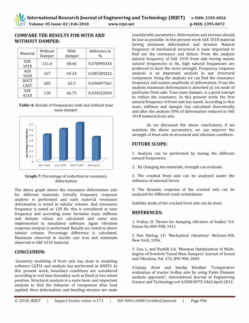
COMPARE THE RESULTS FOR WITH AND WITHOUT DAMPER:
Material Without Damper
With damper
deference in %
SAE 1018
131.4 68.46 0.478995434
AISI 1020
167 69.24 0.585389222
DUCT CAST
205 62.3 0.696097561
SAE 4310
118 66.75 0.434322034
Table-4: Results of frequencies with and without tune
mass damper
Graph-7: Percentage of reduction in resonance deformation
The above graph shows the resonance deformation axle for different materials. Initially frequency response analysis is performed and each material resonance deformation is noted in tabular column. And resonance frequency is noted as 120 Hz. this is considered as tune frequency and according some formulas mass, stiffness and damper values are calculated and same was implemented in simulation software. Again vibration response analysis is performed. Results are noted in above tabular column. Percentage difference is calculated. Maximum observed in ductile cast iron and minimum observed in SAE 4310 material.
CONCLUSION:
Geometry modeling of front axle has done in modeling software CATIA and analysis has performed in ANSYS. In this present work, boundary conditions are considered according to real time boundary such as fixed at two wheel position. Structural analysis is a main basic and important analysis to find the behavior of component after load applied. Here deformation and bending stresses are main
considerable parameters. Deformation and stresses should be low as possible. In this present work SAE 1018 material having minimum deformation and stresses. Natural frequency of mechanical structural is main important to find out the resonance and failure. From the analysis natural frequency of SAE 1018 front axle having maxim natural frequencies in Hz. high natural frequencies are preferred to have the more strength. Frequency response analysis is an important analysis in any structural component. Using the analysis we can find the resonance frequency and maxim amplitude of deformation. From the analysis maximum deformation is absorbed at 1st mode of particular front axle. Tune mass damper, is a good concept to reduce the resonance. In this present work, the first natural frequency of front axle has tuned. According to that mass, stiffness and damper has calculated theoretically and after the analysis 50% of deformation reduced in SAE 1018 material front axle.
As we discussed the above conclusions, if we maintain the above parameters, we can improve the strength of front axle in structural and vibration condition.
FUTURE SCOPE:
1. Analysis can be performed by tuning the different natural frequencies.
2. By changing the materials, strength can evaluate.
3. The cracked front axle can be analyzed under the influence of external forces.
4. The dynamic response of the cracked axle can be analyzed for different crack orientations.
Stability study of the cracked front axle can be done.
REFERENCES:
1. Frahm, H. ‘Device for damping vibration of bodies’ U.S. Patent No.989-958; 1911
2 Den Hartog, J.P. 'Mechanical vibrations’ McGraw-Hill, New York, 1956.
3. Zuo, L. and Nayfeh S.A. ‘Minimax Optimization of Multi-degree-of-freedom Tuned Mass Dampers’ Journal of Sound and Vibration, Vol. 272, 893-908, 2004
4.Sanjay Aloni and Sandip Khedkar “Comparative evaluation of tractor trolley axle by using Finite Element analysis approach”, International Journal of Engineering Science and Technology.vol-4,ISSN:0975-5462,April-2012.

International Research Journal of Engineering and Technology (IRJET) e-ISSN: 2395-0056
Volume: 05 Issue: 02 | Feb-2018 www.irjet.net p-ISSN: 2395-0072
© 2018, IRJET | Impact Factor value: 6.171 | ISO 9001:2008 Certified Journal | Page 997
5. Javad Tarighi, Seyed Saeid Mohtasebi, Reza Alimardani, “Static and dynamic analysis of front axle housing of tractor using finite element methods”, AJAE 2(2), 45-49, 2011.
6. Crandall, S. H. and Mark, W.D. 'Random vibration in mechanical systems’ Academic Press, New York, 1963.
7. McNamara, R.J.. ‘Tuned mass dampers for buildings’ Journal of the Structure Division, ASCE, Vol.103,1985–98, 1977.
8. Luft, R.W. ‘Optimal tuned mass dampers for buildings’ Journal of the Structure Division, ASCE, Vol.105, 2766–72, 1979.
9. Haskett, T. Breukelman, B. Robinson, J. and Kottelenberg, J. ‘Tuned mass dampers under excessive structural excitation’ Report of the Motioneering Inc. Guelph, Ontario, Canada N1K 1B8.
10. Fujino, Y. and Abe, M. ‘Design formulas for tuned mass dampers based on a perturbation technique’ Earthquake Engineering and Structural Dynamics Vol.22, 833–54, 1993.
11. Warburton, G.B. ‘Optimum absorbers for simple systems’ Earthquake Engineering and Structural Dynamics Vol.8, 197–217, 1980.
12. Warburton, G.B. ‘Optimum absorber parameters for various combinations of response and excitation parameters’ Earthquake Engineering and Structural Dynamics, Vol.10, 381–401, 1982.
13. Rana, R. and Soong, T.T. ‘Parametric study and simplified design of tuned mass dampers’ Engineering Structures Vol. 20, 193–204, 1998.